Preparations for Installation, Testing and Commissioning based on Experience at CERN, SNS and Siemens
|
|
|
- Abner Goodman
- 5 years ago
- Views:
Transcription
1 Preparations for Installation, Testing and Commissioning based on Experience at CERN, SNS and Siemens Eugène Tanke FRIB / MSU ESS Seminar, Lund, 6 March 2013
2 Outline Project Goal for the Accelerator Path towards the Goal Technical obstructions on the Path and some Remedies pertaining to installation, testing and commissioning Summary and conclusion 2
3 Project Goal and typical path towards it For the accelerator the Project Goal translates as: Deliver a (fully) integrated and (fully) functional accelerator on time and within budget Reach specified beam performance at the output Given the design, reaching the goal will require Scheduling each of the installation, testing and commissioning phases and doing the actual installation, testing and commissioning and tracking that scope is implemented on schedule and within budget and success is guaranteed... 3

4 Questionable Path towards the Goal 4
5 Preparations for Installation Receiving, Assembly, Testing and Storage area is crucial SNS had RATS facility of more than 5500 m2 Installation will be further aided by Installing tested equipment (FAT*) Service Building: Detailed rack layout and rack installation plan Tunnel: Lattice file, containing names and locations in global coordinates of beam line devices Good estimate and coordination of work involved SNS "Field Coordination" 119 FTEy *Factory Acceptance Test 5
6 Obstructions on the Path towards the Goal (1) Ultimately during beam commissioning (if not sooner) lack of performance may show up Examples of root causes for lack of performance are poor documentation, poor design, poor quality materials, lack of integration, machining errors, cabling errors, software errors, alignment errors, inadequate testing etc Such deficiencies are not uncommon (most if not all labs have their examples) and... can be very costly and time consuming to fix 6
 *")
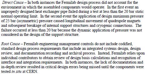
7 Obstructions on the Path towards the Goal Design phase: LHC magnets from FNAL* (2) * 7
, vacuum leaks were detected on the drift")

8 Obstructions on the Path towards the Goal Construction/assembly phase: SNS DTL (3) Shortly before mounting drift tubes in the first SNS DTL tank (#3), vacuum leaks were detected on the drift tubes Leaks were traced to e-beam weld (water/vacuum) E-beam was deflected due to insufficient shunting of the PMQ field, missing the intended joint E-beam penetrated the Cu body and damaged the PMQs 8
 had to be built CERN RFQ2b (200 ma p) with pulsed ion source on the right and linac2 on the")
9 Obstructions on the Path towards the Goal Testing phase: CERN RFQ2a (4) Performance of the CERN RFQ2a was hampered by oil pollution from a roughing pump due to an improperly functioning vacuum interlock system An additional RFQ (RFQ2b) had to be built CERN RFQ2b (200 ma p) with pulsed ion source on the right and linac2 on the left 9
10 Can one reduce the risk of such Obstructions? Proper testing and Q/A procedures combined with full integration will reduce or even eliminate such risk But what exactly should one test and how? In industry the so-called V-model is widely used (see next slide) How can one improve systems integration? 10

11 V-model as defined in industry DVM=Design Verification Method DVP=Design Verification Plan 11
12 V-model applied in an accelerator: Requirements Definition Define and document System Requirements, and the Sub-System, Device requirements and specifications driven by these, e.g. Magnet requirements (45 deg dipole, 5 cm aperture 1T, 1 m, db<0.1%) drive specifications (e.g. RT, n windings of diameter x, 100 A, yoke shape etc) Avoid requirements/specifications that cannot be tested Do not list the same requirements in multiple documents Once device/system built, test against these requirements 12
13 Now we may have a handle on this problem 13
14 V-model applied in an accelerator: Requirements Verification Define and document test plans Define appropriate and comprehensive tests e.g. Leak test a water cooling system with water or with helium? Verify in/out control of diagnostics Test against requirements/specifications and document results Use a Design Verification Matrix (DVM) to track which requirements have been verified 14

 Raster scan Synchrotron")
15 V-model applied in an accelerator: Siemens Particle Therapy systems Layout for Kiel facility (now dismantled) Raster scan Synchrotron and Linac 15
16 Test at vendor where appropriate Test equipment before installation and where appropriate, have as much tested as possible at the vendor (FAT) Avoids time loss due to shipping equipment back Witness construction and tests at vendor Due to schedule pressure, one may be tempted to skimp on testing because after installation and/or during beam commissioning proper functioning of equipment will be confirmed, but... 16
17 Consequences of insufficient / delayed testing (as apposed to thorough / early) If proper functioning of equipment is not confirmed after installation and/or during commissioning, one may suffer substantial delays Commissioning is typically on the critical path increased costs Example: how much does it cost to run the cryoplant during 4 hours of debugging and repair of a magnet problem? (additional) rework "standing army" 17
18 Can one reduce the risk of such Obstructions (to reaching the Goal)? Proper testing and Q/A procedures combined with full integration will reduce or even eliminate such risk But what exactly should one test and how? In industry the so-called V-model is widely used How can one improve systems integration? Preparation: Set up a framework for integration, that allows for tracking of requirements. Industry uses tools such as DOORS or Caliber to assist in the DVM function Preparation: Sign off on interface definition by system owners on both sides of each interface during design Clearly define installation, testing and commissioning phases (see following slide) 18
19 Typical installation, testing and commissioning sequence Given the accelerator design, reaching this sequence will consist of the following phases Building/buying accelerator equipment Equipment testing prior to installation (FAT) Equipment installation (phase A) Equipment testing (stand alone) (phase B) Equipment integration or V test (phase C) Equipment testing with beam (phase pre-d) Equipment beam commissioning (phase D) Project is helped by clearly defining handover points from one phase to the next 19
20 Systems Integration on Site (V tests) "Vertical" Tests (Phase C) are end to end tests across multiple systems When planning these, take installation and commissioning into account To be performed after successful FATs/stand alone tests of all systems concerned Cables should also undergo stand alone testing (Phase B in preparation for C) The cables used to test a device in the FAT are usually not the same cables as installed on the facility Cables may be hooked up to the wrong device/terminals 20
21 Preparations for Beam Commissioning (1) The goal of Beam Commissioning (Phase D) is to achieve the required beam parameters at the output under required conditions In preparation for beam commissioning, beam diagnostics should be tested with a (pilot) beam (Phase pre-d) Testing should include a full V test Subsequently, the beam itself can be commissioned 21
22 Preparations for Beam Commissioning (2) Beam Commissioning is aided by a Beam Commissioning plan, delineating Commissioning team Commissioning sequences, e.g. Source to RFQ input, Source to DTL input Commissioning sequence details Detailed description of measurements to be made and their durations, backed up by beam dynamics simulations, including those away from the nominal setting 22
23 Preparations for Beam Commissioning (3) SNS example of commissioning sequence Example for SNS DTL Tank 1 TASK Ion Source and RFQ Startup Beam transport to MEBT beam stop Beam transport through DTL 1 to Energy Degrader/Faraday Cup Beam transport through DTL to D-plate Beamstop Commission D-plate Diagnostics and MPS Perform Fault Studies RF System Checkout/Verification with Beam Establish Phase and Amplitude Set-point Establish Transverse Matching Conditions Establish Long-Pulse Operation Perform Aperture Scan Establish Nominal 38 ma beam conditions at DTL output Characterize DTL 1 nominal output beam Commission Chopper Systems Characterize DTL 1 chopped output beam High Duty Factor Measurements Other Measurements Duration (shifts) Peak Current (ma) Pulse Width (usec) Rep Rate (Hz) Beam Power (kw) Beam stop MEBT MEBT ED/FC D-plate D-plate D-plate D-plate D-plate D-plate D-plate D-plate D-plate D-plate MEBT D-plate D-plate 23 Priority high high high high high high high high high high low high high med med high low
24 Preparations for Beam Commissioning (4) SNS example of commissioning form Have "sanity check" alternatives In this case, check RF tank amplitude on cavity 24

25 Commissioning is aided by support from beam dynamics tools Various tools: Off-line model(s) On-line model(s) Virtual accelerator RFQ (foto) and linac originally foreseen for SSC being used for production of medical isotopes Loss in beam transport to target was found Debugged with off-line code DYNAC 25
26 Use of multiple beam dynamics codes aids understanding of measured beam During the MEBT commissioning of CERN Linac3, measured and simulated beam emittances and Twiss parameters seemed to be similar, but... double checking with another emittance measurement gear and with another code (DYNAC*) demonstrated flaws in both the simulation and measurement *DYNAC source code available at: 26
27 Success of Commissioning helped by well planned use of temporary diagnostics Apart from using "inline" diagnostics, use strategically placed temporary ones Use emittance scanner to measure beam at the input plane of the RFQ Explore other settings than the nominal one Could condition RFQ in parallel "parking" position Use bunch length, energy and energy dispersion measurements as well as an emittance scanner to characterize the beam at the input plane of the linac Compare measurement results from inline and temporary diagnostics with each other and with beam dynamics code(s) results 27

28 Temporary diagnostics used at the RFQ input and the IH DTL input at Siemens RFQ and IH placed in "parking position", allowing for simultaneous beam commissioning and RF conditioning Siemens AG 2011, Healthcare Sector, Particle Therapy. All rights reserved. 28


29 Examples of temporary Diagnostics Emittance scanner with fast Faraday cup and end cup at location of Siemens RFQ X and Y grids can be read out simultaneously for real time isometric profile plot "D-Plate" used behind SNS DTL tank 1 29
30 Managing Installation, Testing and Commissioning Optimize sequence duration by planning simultaneous installation, testing and commissioning (macroscopic scale) Base durations on bottom-up estimates from system/task owners Have on-site day to day planning (microscopic scale) Define clear handover from one phase to the next e.g. final alignment is part of installation include handover parameters as needed 30

31 SNS CCL during installation and... Photo courtesy of Oak Ridge National Laboratory 8 CCL segments linked by bridge couplers; awaiting installation of inter-segment quadrupoles 31


32 ..simultaneous DTL1 Commissioning PPS Access Ion source & LEBT RFQ DTL tank 1 MEBT D-plate Towards remainder of DTL and CCL D-plate 32
33 Summary highlights Installation, testing and beam commissioning will profit from well defined scope and plans for each of these as well as durations (based on bottom-up estimates from system/task owners) well defined handover from one phase to the next Equipment/system tests are crucial to successful and timely project completion There are methods to reduce the risk and impact of "system failures" 33


34 Conclusion There are methods that will....successfully aid in reaching the end goal and will help avoid undesirable outcome(s) 34
35 Thank you for your attention! 35
Commissioning of Accelerators. Dr. Marc Munoz (with the help of R. Miyamoto, C. Plostinar and M. Eshraqi)
") Commissioning of Accelerators Dr. Marc Munoz (with the help of R. Miyamoto, C. Plostinar and M. Eshraqi) www.europeanspallationsource.se 6 July, 2017 Contents General points Definition of Commissioning
Commissioning of Accelerators Dr. Marc Munoz (with the help of R. Miyamoto, C. Plostinar and M. Eshraqi) www.europeanspallationsource.se 6 July, 2017 Contents General points Definition of Commissioning
Upgrading LHC Luminosity
 1 Upgrading LHC Luminosity 2 Luminosity (cm -2 s -1 ) Present (2011) ~2 x10 33 Beam intensity @ injection (*) Nominal (2015?) 1 x 10 34 1.1 x10 11 Upgraded (2021?) ~5 x10 34 ~2.4 x10 11 (*) protons per
Oak Ridge Spallation Neutron Source Proton Power Upgrade Project and Second Target Station Project
 Oak Ridge Spallation Neutron Source Proton Power Upgrade Project and Second Target Station Project Workshop on the future and next generation capabilities of accelerator driven neutron and muon sources
Linac 4 Instrumentation K.Hanke CERN
 Linac 4 Instrumentation K.Hanke CERN CERN Linac 4 PS2 (2016?) SPL (2015?) Linac4 (2012) Linac4 will first inject into the PSB and then can be the first element of a new LHC injector chain. It will increase
The PEFP 20-MeV Proton Linear Accelerator
 Journal of the Korean Physical Society, Vol. 52, No. 3, March 2008, pp. 721726 Review Articles The PEFP 20-MeV Proton Linear Accelerator Y. S. Cho, H. J. Kwon, J. H. Jang, H. S. Kim, K. T. Seol, D. I.
The ESS Accelerator. For Norwegian Industry and Research. Oslo, 24 Sept Håkan Danared Deputy Head Accelerator Division Group Leader Beam Physics
 The ESS Accelerator For Norwegian Industry and Research Oslo, 24 Sept 2013 Håkan Danared Deputy Head Accelerator Division Group Leader Beam Physics The Hadron Intensity Frontier Courtesy of M. Seidel (PSI)
PRESENT STATUS OF J-PARC
 PRESENT STATUS OF J-PARC # F. Naito, KEK, Tsukuba, Japan Abstract Japan Proton Accelerator Research Complex (J-PARC) is the scientific facility with the high-intensity proton accelerator aiming to realize
2 Work Package and Work Unit descriptions. 2.8 WP8: RF Systems (R. Ruber, Uppsala)
") 2 Work Package and Work Unit descriptions 2.8 WP8: RF Systems (R. Ruber, Uppsala) The RF systems work package (WP) addresses the design and development of the RF power generation, control and distribution
2 Work Package and Work Unit descriptions 2.8 WP8: RF Systems (R. Ruber, Uppsala) The RF systems work package (WP) addresses the design and development of the RF power generation, control and distribution
The Construction Status of CSNS Linac
 The Construction Status of CSNS Linac Sheng Wang Dongguan branch, Institute of High Energy Physics, CAS Sep.2, 2014, Geneva Outline The introduction to CSNS accelerators The commissoning of ion source
ESS: The Machine. Bucharest, 24 April Håkan Danared Deputy Head Accelerator Division. H. Danared Industry & Partner Days Bucharest Page 1
 ESS: The Machine Bucharest, 24 April 2014 Håkan Danared Deputy Head Accelerator Division H. Danared Industry & Partner Days Bucharest Page 1 2025 ESS construction complete 2009 Decision: ESS will be built
OPERATIONAL EXPERIENCE AT J-PARC
 OPERATIONAL EXPERIENCE AT J-PARC Hideaki Hotchi, ) for J-PARC commissioning team ), 2), ) Japan Atomic Energy Agency (JAEA), Tokai, Naka, Ibaraki, 39-95 Japan, 2) High Energy Accelerator Research Organization
LIGHT PROTON THERAPY PROJECT
 17 th of MAY 2018 LIGHT PROTON THERAPY PROJECT Yevgeniy Ivanisenko on behalf of ADAM team FORM-01040-A AVO-ADAM Advanced Oncotherapy (AVO) is a public company ADAM is R&D center of AVO ~ 100 employees
COMMISSIONING SCENARIOS FOR THE J-PARC ACCELERATOR COMPLEX
 COMMISSIONING SCENARIOS FOR THE J-PARC ACCELERATOR COMPLEX T. Koseki, M. Ikegami, M. Tomizawa, Accelerator Laboratory, KEK, Tsukuba, Japan F. Noda, JAEA, Tokai, Japan Abstract The J-PARC (Japan Proton
Proton Engineering Frontier Project
 Proton Engineering Frontier Project OECD Nuclear Energy Agency Fifth International Workshop on the Utilisation and Reliability of High Power Proton Accelerators (HPPA5) (6-9 May 2007, Mol, Belgium) Yong-Sub
Workshop on Accelerator Operations August 6-10, 2012 Glen D. Johns Accelerator Operations Manager
 HWDB: Operations at the Spallation Neutron Source Workshop on Accelerator Operations August 6-10, 2012 Glen D. Johns Accelerator Operations Manager Outline Facility overview Organization Shift schedule
AREAL- Phase 1. B. Grigoryan on behalf of AREAL team
 AREAL- Phase 1 Progress & Status B. Grigoryan on behalf of AREAL team Contents Machine Layout Building & Infrastructure Laser System RF System Vacuum System Cooling System Control System Beam Diagnostics
BEAM DIAGNOSTICS IN THE CNAO INJECTION LINES COMMISSIONING
 BEAM DIAGNOSTICS IN THE CNAO INJECTION LINES COMMISSIONING A. Parravicini, G. Balbinot, J. Bosser, E. Bressi, M. Caldara, L. Lanzavecchia, M. Pullia, M. Spairani, CNAO Foundation, Pavia, Italy C. Biscari,
Welcome and FRIB Project Status. FRIB Highlights and Plan Ahead
 Welcome and FRIB Project Status Thomas Glasmacher Project Manager This material is based upon work supported by the U.S. Department of Energy Office of Science under Cooperative Agreement DE-SC0000661.
Particle Beam Production - A Synchrotron-Based System - Prof. Dr. Thomas Haberer Scientific-technical Director Heidelberg Iontherapy Center
 Particle Beam Production - A Synchrotron-Based System - Prof. Dr. Thomas Haberer Scientific-technical Director Heidelberg Iontherapy Center Outline Situation/Rationale Requirements Synchrotron choice Functions
Beam Loss Detection for MPS at FRIB
 Beam Loss Detection for MPS at FRIB Zhengzheng Liu Beam Diagnostics Physicist This material is based upon work supported by the U.S. Department of Energy Office of Science under Cooperative Agreement DE-SC0000661.
RF plans for ESS. Morten Jensen. ESLS-RF 2013 Berlin
 RF plans for ESS Morten Jensen ESLS-RF 2013 Berlin Overview The European Spallation Source (ESS) will house the most powerful proton linac ever built. The average beam power will be 5 MW which is five
Detailed Design Report
 Detailed Design Report Chapter 4 MAX IV Injector 4.6. Acceleration MAX IV Facility CHAPTER 4.6. ACCELERATION 1(10) 4.6. Acceleration 4.6. Acceleration...2 4.6.1. RF Units... 2 4.6.2. Accelerator Units...
HIGH-INTENSITY PROTON BEAMS AT CERN AND THE SPL STUDY
 HIGH-INTENSITY PROTON BEAMS AT CERN AND THE STUDY E. Métral, M. Benedikt, K. Cornelis, R. Garoby, K. Hanke, A. Lombardi, C. Rossi, F. Ruggiero, M. Vretenar, CERN, Geneva, Switzerland Abstract The construction
DELIVERY RECORD. Location: Ibaraki, Japan
 DELIVERY RECORD Client: Japan Atomic Energy Agency (JAEA) High Energy Accelerator Research Organization (KEK) Facility: J-PARC (Japan Proton Accelerator Research Complex) Location: Ibaraki, Japan 1 October
Linac3 experience for LHC ion runs
 Linac3 experience for LHC ion runs G Bellodi for the Linac3 team Keywords: beam performance reliability set up time results of MDs remaining unknowns 1 A year in perspective Source removed: change of main
LHC Beam Instrumentation Further Discussion
 LHC Beam Instrumentation Further Discussion LHC Machine Advisory Committee 9 th December 2005 Rhodri Jones (CERN AB/BDI) Possible Discussion Topics Open Questions Tune measurement base band tune & 50Hz
3 cerl. 3-1 cerl Overview. 3-2 High-brightness DC Photocathode Gun and Gun Test Beamline
 3 cerl 3-1 cerl Overview As described before, the aim of the cerl in the R&D program includes the development of critical components for the ERL, as well as the construction of a test accelerator. The
THE OPERATION EXPERIENCE AT KOMAC*
 THAM2X01 Proceedings of HB2016, Malmö, Sweden THE OPERATION EXPERIENCE AT KOMAC* Yong-Sub Cho, Kye-Ryung Kim, Kui Young Kim, Hyeok-Jung Kwon, Han-Sung Kim, Young-Gi Song Korea Atomic Energy Research Institute,
The FAIR plinac RF Systems
 The FAIR plinac RF Systems Libera Workshop Sep. 2011 Gerald Schreiber Gerald Schreiber, GSI RF Department 2 (1) Overview GSI / FAIR (2) FAIR Proton Linear Accelerator "plinac" (3) plinac RF Systems (4)
30 GHz Power Production / Beam Line
 30 GHz Power Production / Beam Line Motivation & Requirements Layout Power mode operation vs. nominal parameters Beam optics Achieved performance Problems Beam phase switch for 30 GHz pulse compression
P. Emma, et al. LCLS Operations Lectures
 P. Emma, et al. LCLS Operations Lectures LCLS 1 LCLS Accelerator Schematic 6 MeV 135 MeV 250 MeV σ z 0.83 mm σ z 0.83 mm σ z 0.19 mm σ δ 0.05 % σ δ 0.10 % σ δ 1.6 % Linac-0 L =6 m rf gun L0-a,b Linac-1
5 Project Costs and Schedule
 93 5 Project Costs and Schedule 5.1 Overview The cost evaluation for the integrated version of the XFEL with 30 experiments and 35 GeV beam energy as described in the TDR-2001 yielded 673 million EUR for
Commissioning the TAMUTRAP RFQ cooler/buncher. E. Bennett, R. Burch, B. Fenker, M. Mehlman, D. Melconian, and P.D. Shidling
 Commissioning the TAMUTRAP RFQ cooler/buncher E. Bennett, R. Burch, B. Fenker, M. Mehlman, D. Melconian, and P.D. Shidling In order to efficiently load ions into a Penning trap, the ion beam should be
The SPL at CERN. slhc. 1. Introduction 2. Description. 3. Status of the SPL study. - Stage 1: Linac4 - Stage 2: LP-SPL - Potential further stages
 The SPL at CERN 1. Introduction 2. Description - Stage 1: Linac4 - Stage 2: LP-SPL - Potential further stages 3. Status of the SPL study slhc Roa Garoby for the SPL team 1. Introduction Motivation for
III. Proton-therapytherapy. Rome SB - 3/5 1
 Outline Introduction: an historical review I Applications in medical diagnostics Particle accelerators for medicine Applications in conventional radiation therapy II III IV Hadrontherapy, the frontier
EPJ Web of Conferences 95,
 EPJ Web of Conferences 95, 04012 (2015) DOI: 10.1051/ epjconf/ 20159504012 C Owned by the authors, published by EDP Sciences, 2015 The ELENA (Extra Low Energy Antiproton) project is a small size (30.4
A Fifteen Year Perspective on the Design and Performance of the SNS Accelerator
 A Fifteen Year Perspective on the Design and Performance of the SNS Accelerator S. Cousineau (On behalf of the SNS project) HB2016, Sweden July 04, 2016 ORNL is managed by UT-Battelle for the US Department
A Cathode Development Cornell Cultera This scope includes all labor and purchases required produce photocathodes required by CBETA.
 A1.01 PROJECT MANAGEMENT BNL/Cornell Michnoff A1.01.01 Milestones BNL/Cornell Michnoff This scope is a placeholder for all project high level milestones for NYSERDA. There is no cost or labor related to
STATUS OF THE SWISSFEL C-BAND LINEAR ACCELERATOR
 Proceedings of FEL213, New York, NY, USA STATUS OF THE SWISSFEL C-BAND LINEAR ACCELERATOR F. Loehl, J. Alex, H. Blumer, M. Bopp, H. Braun, A. Citterio, U. Ellenberger, H. Fitze, H. Joehri, T. Kleeb, L.
STATUS OF THE SwissFEL C-BAND LINAC
 STATUS OF THE SwissFEL C-BAND LINAC F. Loehl, J. Alex, H. Blumer, M. Bopp, H. Braun, A. Citterio, U. Ellenberger, H. Fitze, H. Joehri, T. Kleeb, L. Paly, J.-Y. Raguin, L. Schulz, R. Zennaro, C. Zumbach,
PEP II Design Outline
 PEP II Design Outline Balša Terzić Jefferson Lab Collider Review Retreat, February 24, 2010 Outline General Information Parameter list (and evolution), initial design, upgrades Collider Ring Layout, insertions,
CERN S PROTON SYNCHROTRON COMPLEX OPERATION TEAMS AND DIAGNOSTICS APPLICATIONS
 Marc Delrieux, CERN, BE/OP/PS CERN S PROTON SYNCHROTRON COMPLEX OPERATION TEAMS AND DIAGNOSTICS APPLICATIONS CERN s Proton Synchrotron (PS) complex How are we involved? Review of some diagnostics applications
Status of RF Power and Acceleration of the MAX IV - LINAC
 Status of RF Power and Acceleration of the MAX IV - LINAC Dionis Kumbaro ESLS RF Workshop 2015 MAX IV Laboratory A National Laboratory for synchrotron radiation at Lunds University 1981 MAX-lab is formed
Karin Rathsman, Håkan Danared and Rihua Zeng. Report from RF Power Source Workshop
 Accelerator Division ESS AD Technical Note ESS/AD/0020 Karin Rathsman, Håkan Danared and Rihua Zeng Report from RF Power Source Workshop 10 July 2011 Report on the RF Power Source Workshop K. Rathsman,
4.4 Injector Linear Accelerator
 4.4 Injector Linear Accelerator 100 MeV S-band linear accelerator based on the components already built for the S-Band Linear Collider Test Facility at DESY [1, 2] will be used as an injector for the CANDLE
The Beam Test Facility at the SNS
 The Beam Test Facility at the SNS R.F. Welton, A. Aleksandrov, B.X. Han, Y.W. Kang, M.M. Middendorf, S.N. Murray, M. Piller, T.R. Pennisi, V. Peplov, R. Saethre, M. Santana, C. Stinson, M.P. Stockli and
A HIGH-POWER SUPERCONDUCTING H - LINAC (SPL) AT CERN
 AT CERN") A HIGH-POWER SUPERCONDUCTING H - LINAC (SPL) AT CERN E. Chiaveri, CERN, Geneva, Switzerland Abstract The conceptual design of a superconducting H - linear accelerator at CERN for a beam energy of 2.2 GeV
A HIGH-POWER SUPERCONDUCTING H - LINAC (SPL) AT CERN E. Chiaveri, CERN, Geneva, Switzerland Abstract The conceptual design of a superconducting H - linear accelerator at CERN for a beam energy of 2.2 GeV
IOT OPERATIONAL EXPERIENCE ON ALICE AND EMMA AT DARESBURY LABORATORY
 IOT OPERATIONAL EXPERIENCE ON ALICE AND EMMA AT DARESBURY LABORATORY A. Wheelhouse ASTeC, STFC Daresbury Laboratory ESLS XVIII Workshop, ELLETRA 25 th 26 th November 2010 Contents Brief Description ALICE
PEP-II Overview & Ramp Down Plan. J. Seeman DOE PEP-II Ramp Down-D&D Review August 6-7, 2007
 PEP-II Overview & Ramp Down Plan J. Seeman DOE PEP-II Ramp Down-D&D Review August 6-7, 2007 Topics Overview of the PEP-II Collider PEP-II turns off September 30, 2008. General list of components and buildings
Upgrade of CEBAF to 12 GeV
 Upgrade of CEBAF to 12 GeV Leigh Harwood (for 12 GeV Accelerator team) Page 1 Outline Background High-level description Schedule Sub-system descriptions and status Summary Page 2 CEBAF Science Mission
SRS and ERLP developments. Andrew moss
 SRS and ERLP developments Andrew moss Contents SRS Status Latest news Major faults Status Energy Recovery Linac Prototype Latest news Status of the RF system Status of the cryogenic system SRS Status Machine
Practical Application of the Phased-Array Technology with Paint-Brush Evaluation for Seamless-Tube Testing
 ECNDT 2006 - Th.1.1.4 Practical Application of the Phased-Array Technology with Paint-Brush Evaluation for Seamless-Tube Testing R.H. PAWELLETZ, E. EUFRASIO, Vallourec & Mannesmann do Brazil, Belo Horizonte,
BEAM DYNAMICS AND EXPERIMENT OF CPHS LINAC *
 BEAM DYNAMICS AND EXPERIMENT OF CPHS LINAC * L. Du #, C.T. Du, X.L. Guan, C.X. Tang, R. Tang, X.W. Wang, Q.Z. Xing, S.X. Zheng, Key Laboratory of Particle & Radiation Imaging (Tsinghua University), Ministry
Progress of Beam Instrumentation in J-PARC Linac
 IBIC2012 International Beam Instrumentation Conference Tsukuba, Ibaraki, JAPAN, 1 st to 4 th, Oct. 2011 Progress of Beam Instrumentation in J-PARC Linac Akihiko MIURA with the Beam Monitor Group in J-PARC
High Brightness Injector Development and ERL Planning at Cornell. Charlie Sinclair Cornell University Laboratory for Elementary-Particle Physics
 High Brightness Injector Development and ERL Planning at Cornell Charlie Sinclair Cornell University Laboratory for Elementary-Particle Physics June 22, 2006 JLab CASA Seminar 2 Background During 2000-2001,
Concept and R&D Plans for Project X
 Concept and R&D Plans for Project X Giorgio Apollinari 9 th ICFA Seminar SLAC, Oct. 2008 HB2008 Project X for Intensity Frontier Physics 1 Introduction Intensity Frontier: Needs and Physics Justification
Tutorial: Trak design of an electron injector for a coupled-cavity linear accelerator
 Tutorial: Trak design of an electron injector for a coupled-cavity linear accelerator Stanley Humphries, Copyright 2012 Field Precision PO Box 13595, Albuquerque, NM 87192 U.S.A. Telephone: +1-505-220-3975
PEP II STATUS AND PLANS *
 PEP II STATUS AND PLANS * John T. Seeman + Stanford Linear Accelerator Center, Stanford University, Stanford, CA 94309 USA The PEP II B-Factory 1 project is an e + e - colliding beam storage ring complex
SLAC R&D Program for a Polarized RF Gun
 ILC @ SLAC R&D Program for a Polarized RF Gun SLAC-PUB-11657 January 2006 (A) J. E. CLENDENIN, A. BRACHMANN, D. H. DOWELL, E. L. GARWIN, K. IOAKEIMIDI, R. E. KIRBY, T. MARUYAMA, R. A. MILLER, C. Y. PRESCOTT,
TECHNICAL SPECIFICATION Multi-beam S-band Klystron type BT267
 TECHNICAL SPECIFICATION Multi-beam S-band Klystron type BT267 The company was created for the development and manufacture of precision microwave vacuum-electron-tube devices (VETD). The main product areas
Diamond RF Status (RF Activities at Daresbury) Mike Dykes
 Mike Dykes") Diamond RF Status (RF Activities at Daresbury) Mike Dykes ASTeC What is it? What does it do? Diamond Status Linac Booster RF Storage Ring RF Summary Content ASTeC ASTeC was formed in 2001 as a centre of
Diamond RF Status (RF Activities at Daresbury) Mike Dykes ASTeC What is it? What does it do? Diamond Status Linac Booster RF Storage Ring RF Summary Content ASTeC ASTeC was formed in 2001 as a centre of
1. General principles for injection of beam into the LHC
 LHC Project Note 287 2002-03-01 Jorg.Wenninger@cern.ch LHC Injection Scenarios Author(s) / Div-Group: R. Schmidt / AC, J. Wenninger / SL-OP Keywords: injection, interlocks, operation, protection Summary
Status of SOLARIS Arkadiusz Kisiel
 Status of SOLARIS Arkadiusz Kisiel Solaris National Synchrotron Light Source Jagiellonian University Czerwone Maki 98 30-392 Kraków www.synchrotron.uj.edu.pl Arkadiusz.Kisiel@uj.edu.pl On behalf of SOLARIS
RF considerations for SwissFEL
 RF considerations for H. Fitze in behalf of the PSI RF group Workshop on Compact X-Ray Free Electron Lasers 19.-21. July 2010, Shanghai Agenda Introduction RF-Gun Development C-band development Summary
Characterizing Transverse Beam Dynamics at the APS Storage Ring Using a Dual-Sweep Streak Camera
 Characterizing Transverse Beam Dynamics at the APS Storage Ring Using a Dual-Sweep Streak Camera Bingxin Yang, Alex H. Lumpkin, Katherine Harkay, Louis Emery, Michael Borland, and Frank Lenkszus Advanced
P. Adamson, Fermi National Accelerator Laboratory, Batavia, IL 60510, USA. Abstract
 Abstract 7 0 0 k W M A I N I N J E C T O R O P E R A T I O N S F O R N O νa AT FNAL P. Adamson, Fermi National Accelerator Laboratory, Batavia, IL 60510, USA Following a successful career as an antiproton
Design Studies For The LCLS 120 Hz RF Gun Injector
 BNL-67922 Informal Report LCLS-TN-01-3 Design Studies For The LCLS 120 Hz RF Gun Injector X.J. Wang, M. Babzien, I. Ben-Zvi, X.Y. Chang, S. Pjerov, and M. Woodle National Synchrotron Light Source Brookhaven
An Overview of Beam Diagnostic and Control Systems for AREAL Linac
 An Overview of Beam Diagnostic and Control Systems for AREAL Linac Presenter G. Amatuni Ultrafast Beams and Applications 04-07 July 2017, CANDLE, Armenia Contents: 1. Current status of existing diagnostic
ANKA RF System - Upgrade Strategies
 ANKA RF System - Upgrade Strategies Vitali Judin ANKA Synchrotron Radiation Facility 2014-09 - 17 KIT University of the State Baden-Wuerttemberg and National Laboratory of the Helmholtz Association www.kit.edu
Development of an Abort Gap Monitor for High-Energy Proton Rings *
 Development of an Abort Gap Monitor for High-Energy Proton Rings * J.-F. Beche, J. Byrd, S. De Santis, P. Denes, M. Placidi, W. Turner, M. Zolotorev Lawrence Berkeley National Laboratory, Berkeley, USA
PRACTICAL APPLICATION OF THE PHASED-ARRAY TECHNOLOGY WITH PAINT-BRUSH EVALUATION FOR SEAMLESS-TUBE TESTING
 PRACTICAL APPLICATION OF THE PHASED-ARRAY TECHNOLOGY WITH PAINT-BRUSH EVALUATION FOR SEAMLESS-TUBE TESTING R.H. Pawelletz, E. Eufrasio, Vallourec & Mannesmann do Brazil, Belo Horizonte, Brazil; B. M. Bisiaux,
Next Linear Collider. The 8-Pack Project. 8-Pack Project. Four 50 MW XL4 X-band klystrons installed on the 8-Pack
 The Four 50 MW XL4 X-band klystrons installed on the 8-Pack The Demonstrate an NLC power source Two Phases: 8-Pack Phase-1 (current): Multi-moded SLED II power compression Produce NLC baseline power: 475
Report on the LCLS Injector Technical Review
 Report on the LCLS Injector Technical Review Stanford Linear Accelerator Center November 3&4, 2003 Committee Members Prof. Patrick G. O Shea, Chair, University of Maryland Dr. Eric Colby, Stanford Linear
Status of SOLARIS. Paweł Borowiec On behalf of Solaris Team
 Status of SOLARIS Paweł Borowiec On behalf of Solaris Team e-mail: pawel.borowiec@uj.edu.pl XX ESLS-RF Meeting, Villingen 16-17.11.2016 Outline 1. Timeline 2. Injector 3. Storage ring 16-17.11.2016 XX
The Elettra Storage Ring and Top-Up Operation
 The Elettra Storage Ring and Top-Up Operation Emanuel Karantzoulis Past and Present Configurations 1994-2007 From 2008 5000 hours /year to the users 2010: Operations transition year Decay mode, 2 GeV (340mA)
EUROFEL-Report-2007-DS EUROPEAN FEL Design Study
 EUROFEL-Report-2007-DS4-095 EUROPEAN FEL Design Study Deliverable N : D 4.3 Deliverable Title: Task: Authors: Generation of 3rd harmonic photons at 90 nm DS-4 see next page Contract N : 011935 Project
Nick Walker DESY MAC
 Nick Walker DESY MAC 4.5.2006 XFEL X-Ray Free-Electron Laser DESY ILC Project Group Accelerator Experimentation Behnke, Elsen, Walker (chair) WP 15, 16 WP 4-7 Accelerator Physics and Design WP 6 High Gradient
The basic parameters of the pre-injector are listed in the Table below. 100 MeV
 3.3 The Pre-injector The high design brightness of the SLS requires very high phase space density of the stored electrons, leading to a comparatively short lifetime of the beam in the storage ring. This,
Review of Diamond SR RF Operation and Upgrades
 Review of Diamond SR RF Operation and Upgrades Morten Jensen on behalf of Diamond Storage Ring RF Group Agenda Stats X-ray and LN2 pressure results Cavity Failure Conditioning in the RFTF Cavity Simulations
Experience with the Cornell ERL Injector SRF Cryomodule during High Beam Current Operation
 Experience with the Cornell ERL Injector SRF Cryomodule during High Beam Current Operation Matthias Liepe Assistant Professor of Physics Cornell University Experience with the Cornell ERL Injector SRF
PICS IN THE INJECTOR COMPLEX WHAT ARE WE TALKING ABOUT?
 Published by CERN in the Proceedings of RLIUP: Review of LHC and Injector Upgrade Plans, Centre de Convention, Archamps, France, 29 31 October 2013, edited by B. Goddard and F. Zimmermann, CERN 2014 006
PEP II Status and Plans
 SLAC-PUB-6854 September 1998 PEP II Status and Plans By John T. Seeman Invited talk presented at the 16th IEEE Particle Accelerator Conference (PAC 95) and International Conference on High Energy Accelerators,
ESS Linac WP8 Radio Frequency Systems and Test Facilities
 ESS Linac WP8 Radio Frequency Systems and Test Facilities ESS TAC Lund, 8 July 2010 Roger Ruber (Uppsala University) for the ESS Linac RF Team Outline Work Package description Objectives Organization Technical
CLIC Feasibility Demonstration at CTF3
 CLIC Feasibility Demonstration at CTF3 Roger Ruber Uppsala University, Sweden, for the CLIC/CTF3 Collaboration http://cern.ch/clic-study LINAC 10 MO303 13 Sep 2010 The Key to CLIC Efficiency NC Linac for
SABER A Facility for Accelerator Physics and Test Beam Experiments Roger Erickson SABER Workshop March 15, 2006
 SABER A Facility for Accelerator Physics and Test Beam Experiments Roger Erickson SABER Workshop March 15, 2006 FFTB will soon be gone! The Problem: On April 10, 2006, the Final Focus Test Beam (FFTB)
Towards an X-Band Power Source at CERN and a European Structure Test Facility
 Towards an X-Band Power Source at CERN and a European Structure Test Facility Erk Jensen and Gerry McMomagle CERN The X-Band Accelerating Structure Design and Test-Program Workshop Day 2: Structure Testing
Beam Losses During LCLS Injector Phase-1 1 Operation
 Beam Losses During LCLS Injector Phase-1 1 Operation & Paul Emma September 28, 2006 Radiation Safety Committee Review Scope of Phase 1 Operation Request for Three Operating Modes Operating Plan for Phase
Accelerator Instrumentation RD. Monday, July 14, 2003 Marc Ross
 Monday, Marc Ross Linear Collider RD Most RD funds address the most serious cost driver energy The most serious impact of the late technology choice is the failure to adequately address luminosity RD issues
The European Spallation Source
 The European Spallation Source Roger Ruber Uppsala University NIKHEF industriemiddag 21 september 2011 The European Spallation Source Roger Ruber - The European Spallation Source NIKHEF, 21-Sep-2011 page
Summary of the 1 st Beam Line Review Meeting Injector ( )
") Summary of the 1 st Beam Line Review Meeting Injector (23.10.2006) 15.11.2006 Review the status of: beam dynamics understanding and simulations completeness of beam line description conceptual design of
Summary of the 1 st Beam Line Review Meeting Injector (23.10.2006) 15.11.2006 Review the status of: beam dynamics understanding and simulations completeness of beam line description conceptual design of
Recent APS Storage Ring Instrumentation Developments. Glenn Decker Advanced Photon Source Beam Diagnostics March 1, 2010
 Recent APS Storage Ring Instrumentation Developments Glenn Decker Advanced Photon Source Beam Diagnostics March 1, 2010 Ring Diagnostics Overview RF beam position monitor technology Photon beam position
LCLS Injector Technical Review
 LCLS Injector Technical Review Stanford Linear Accelerator Center November 3&4 2003 Review Committee Members: Prof. Patrick O Shea Chair University of Maryland Dr. E. Colby Stanford Linear Accelerator
HIGH POWER BEAM DUMP AND TARGET / ACCELERATOR INTERFACE PROCEDURES *
 HIGH POWER BEAM DUMP AND TARGET / ACCELERATOR INTERFACE PROCEDURES * J. Galambos, W. Blokland, D. Brown, C. Peters, M. Plum, Spallation Neutron Source, ORNL, Oak Ridge, TN 37831, U.S.A. Abstract Satisfying
Equipment Installation, Planning, Layout, organisation and updates
 Equipment Installation, Planning, Layout, organisation and updates Simon Mataguez, Julie Coupard with contributions of the LIU-PLI team Table of contents: LIU installation activities Organisation of the
LCLS RF Reference and Control R. Akre Last Update Sector 0 RF and Timing Systems
 LCLS RF Reference and Control R. Akre Last Update 5-19-04 Sector 0 RF and Timing Systems The reference system for the RF and timing starts at the 476MHz Master Oscillator, figure 1. Figure 1. Front end
Hadron Therapy Technologies
 Hadron Therapy Technologies S. Peggs, BNL & ESS-S Bevalac 1950-1993 Many figures courtesy of Jay Flanz 1 Consumer demand 1 in 3 Europeans will confront some form of cancer in their lifetime. Cancer is
A Facility for Accelerator Physics and Test Beam Experiments
 A Facility for Accelerator Physics and Test Beam Experiments U.S. Department of Energy Review Roger Erickson for the FACET Design Team February 20, 2008 SLAC Overview with FACET FACET consists of four
Status of the FAIR Project. Jürgen Henschel FAIR Project Leader / Technical Director GSI & FAIR
 Status of the FAIR Project Jürgen Henschel FAIR Project Leader / Technical Director GSI & FAIR Finland France Germany India Poland Romania Russia Slovenia Sweden UK FAIR Strategic objectives FAIR phase
Linac strategies for the lower beam energies. U. Ratzinger
 Linac strategies for the lower beam energies U. Ratzinger Institute for Applied Physics, J.W.Goethe-University Frankfurt TCADS-2 Workshop Technology and Components of Accelerator Driven Systems Nantes
UPGRADES TO THE ISIS SPALLATION NEUTRON SOURCE
 UPGRADES TO THE ISIS SPALLATION NEUTRON SOURCE C.R. Prior, CCLRC Rutherford Appleton Laboratory, Chilton, Didcot, Oxon, U.K. Abstract With studies of a European Spallation Source (ESS) suspended and high-level