Linac strategies for the lower beam energies. U. Ratzinger
|
|
|
- Alexander Bell
- 5 years ago
- Views:
Transcription
1 Linac strategies for the lower beam energies U. Ratzinger Institute for Applied Physics, J.W.Goethe-University Frankfurt TCADS-2 Workshop Technology and Components of Accelerator Driven Systems Nantes May 21 st - 23 rd,
2 Accelerator Concepts Claim Linacs are the only choice above a certain level of time averaged or pulsed beam current request. But it is not fixed, where these limits are, and they are depending on the state of the art in a manifold of technologies, like: RF amplifiers, RF resonators, surface treatment and analysis Cryotechnology, room temperature cooling technique Magnet and vacuum technology Beam diagnostics, alignment concepts Ion production and beam formation New developments like laser acceleration, plasma wake field acceleraion 2

3 In Memoriam Horst Klein Courtesy of Holger Podlech 3

4 Accelerator Concepts LINAC Example: E 7MV / m Electrostatic beam formation and acceleration by rf cavities 100 MHz 10 GHz 1 MV/m 25 MV/m cw operation pulsed s.c. or r.t. β 0.01 β 1 Transverse beam focusing by magnetic lenses mostly Disadvantages of Linacs: -One dimensional array makes problems in the acquisition of a suited building site, length proportional to end energy -Very large and expensive rf amplifier installations needed 4
5 Accelerator Concepts Improved reliability and efficiency of Linacs need 1. Higher acceleration fields 2. Improved rf amplifier technology 3. Superconducting (sc) versus room temperature (rt) technology investigation 4. Adequate beam dynamics and simulations 5. beam loss reduction These topics will be discussed now 5
6 Higher acceleration fields 1. Field limits Fowler-Nordheim eq. for rf-operation: 2.5 d(ln( IF / E ) / d(1/ E) k I F k E F f field emission current; ( ) ; E material dependent field enhancement factor; E ; / electric field; ; E E surf for ideal surfaces Typical -range:
7 Higher acceleration fields Kilpatrick criterion for the limiting electric field E = V/g, gap width g f 1.64 E E e ; E / MV / m ; f / MHz Fit to experiments f / MHz E / MV/m GSI-HSI, 36 MHz too pessimistic DESY-Tesla, 1.3 GHz SLAC too optimistic CERN CLIC-TF 7


8 Higher acceleration fields, SC Cavities R&D on elliptical cavities for high beta linac sections with general impact DESY, TESLA - cavity Tesla type cavities 50 MV/m at 1.3 GHz, 2K! Critical magn. field would allow up to 57 MV/m! 8

 is reached")
9 Higher acceleration fields Aiming for high acceleration field, surface preparation Accelerating gradient / MV/m Achieved Q/E curves for Tesla cavities at DESY, D.Reschke et al. At ~ 50 MV/m the magnetic field limit of Nb (~ 200 mt) is reached for the TESLA type cavity. 9

10 Higher acceleration fields S.C. low energy structure development at IAP Frankfurt, 4 K 325 MHz, 4 K, 10 % speed of light 2006 = =
 and outcoupled (pink) rf signal; 100 ms per div. Quality factor against effective field gradient.")
11 Higher acceleration fields Superconducting CH Cavity Development at IAP Incoupled (yellow), reflected (blue) and outcoupled (pink) rf signal; 100 ms per div. Quality factor against effective field gradient. 11


12 State of the art results, SC cavities Single Spoke cavity during fabrication Lit. on Spoke cavities: M. Kelly, Superconducting Spoke Cavities, Proc. Of the LINAC12 Conf., Tsukuba, p

13 State of the art results, RT cavities CERN Linac 3, design: 33 MV voltage gain along 8 m beam line Effective voltage gain of 4.1 MV/m IH-Tank / 202 MHz combination, in operation since

14 State of the art results, RT cavities HIT Heidelberg, 7 AMeV C4+ - Therapy injector, 20 MV on 3.8 m 5.25 MV/m effective voltage gain! 217 MHz, in operation at HIT Heidelberg, CNAO Pavia, under construction at Marburg, Shanghei, Medaustron at Wiener Neustadt 14
15 State of the art results, RT High power tests on CERN Linac 3, IH-Tank 2 Surface fields up to 54 MV/m, eff. acceleration up to 10.7 MV/m 15
16 RT cavity R&D New BMBF -project at IAP Frankfurt: Layout, construction, surface treatment and rf power tests on a 325 MHz, r.t. CH - cavity Table 1: The main CH cavity parameters for the high field gradient prototype. Number of Gaps 7 Frequency (MHz) Voltage Gain (MV) 6 Eff. Accel. Length (mm) Eff. Accel. Field (MV/m) 11.2 Power Loss (MW) 1.58 Q 0 value Effective Shunt impedance (MΩ/m) 57.3 Beam Aperture (mm) 27 16


17 RT cavity R&D E -field distribution B -field distribution E -field distribution along z-axis and in parallel at the aperture radius of 13.5 mm Eff. gap voltage distribution 17


18 E max spots at r = mm for each drift tube and half drift tube Azimuthal field strength distribution for drift tube no. 3 (evidence for a modest quadrupole field component) 18
19 Improved rf amplifier technology P/kW pulsed Power Tubes Klystrons cw Rapid Development: Solid state amplifiers 10 2 Klystrodes f/mhz 19

20 Improved rf amplifier technology Tube driven cavity amplifiers 10 MHz to 300 MHz Problems: Shrinking market because of revolution in communication technology power tube logistics, delivery guarantees, quality control This is affecting heavy ion facilities mainly. 20
 - Becomes quite bulky at lower frequencies - expensive modulator developments for every beam pulse structure (100 kv.")
21 Improved rf amplifier technology Power klystron technology pushed by electron machines first (SLAC) Meanwhile frequencies down to 325 MHz are well established. Advantage: Disadvantage: - Long lifetime (about hours typically) - Becomes quite bulky at lower frequencies - expensive modulator developments for every beam pulse structure (100 kv. few 100 kv) Toshiba, 3 MW, 325 MHz Klystron, 100 kv modulator to be developed specifically. 21
 Very attractive prizes in case of pulsed operation: (up to some 10 kw per transistor feasible, V up to 1 kv) Forced liquid cooling Service during operation at")
22 Solid state amplifiers Improved rf amplifier technology MOSFET transistors develop rapidly: Output power per transistor doubled every year Besides Si based technology (Freescale ) in future also SiC technology may contribute (Infineon ) Very attractive prizes in case of pulsed operation: (up to some 10 kw per transistor feasible, V up to 1 kv) Forced liquid cooling Service during operation at reduced power possible Falling investment costs per 1kW of installed power Example in Si technology: 30 kw cw, MHz, Three 19 inch racks like shown in the photo will do the job. Rf to plug power efficiency about 55 %;Mass about 1800 kg. (Photo Digital Broadcast DB, Padova, Italy) 22
23 x [mm] Efficient transverse focusing Linac focusing elements: Quadrupole singlet, doublet and triplet channels 10 F 0 D 0 F 0 D 0 beam envelope x F D F D L p (z) z 0 particle trajectory y d L q z -10 D F D F z [m] FODO channel, 30 deg phase advance 23

 Phys.")
24 Efficient transverse focusing Especially at low beam energies DTL s with integrated electromagnetic quadrupoles suffer from multipacting between tubes with large outer diameter. A new trend is to use more compact permanent magnetic quadrupoles. At Los Alamos, IH-DTL development with PMQ s is underway (S.S. Kurennoy et al.) Phys.Rev.STAB
25 Efficient transverse focusing Quadrupole triplet focusing between r.t. CH cavities at FAIR proton linac: 3-70 MeV, 70 ma, 22 m. Beam dynamics G. Clemente et al. IPAC10. 25


26 Efficient transverse focusing Mechanical concept, 3 35 MeV, 70 ma section: A 9 m long tank consists of 3 coupled CH cavities. Every second triplet is housed in a drift tube for rf coupling to CH drift tube sections. Doublets and triplets can be aligned mechanically at the workshop and form a complete transverse focusing unit. Not true for singlet channels! Prototype cavity under construction at IAP 26

27 Efficient transverse focusing Solenoid Quarter wave resonator S.C. solenoids integrated in cryostat with cavities. Coaxial shielding end coils provide steep field edges to protect the cavities. TRIUMF ISAC2, Vancouver, Canada R. Laxdal et al. LINAC

28 SC versus RT technology, duty factor S.C. CH cavity, 325 MHz against pulsed R.T. CH cavity, 325 MHz; β S.C. cavity ready for cold tests R.T. cavity under design Cavity development at IAP Frankfurt and in cooperation with GSI Darmstadt 28


29 SC versus RT technology, duty factor Fabrication of the new 325 MHz CH cavity, β = 0.15, at Company RI, Bergisch- Gladbach, and two doctorands during an RF tuning procedure 29


30 SC versus RT technology, duty factor First measurements on the new 325 MHz CH cavity at IAP Frankfurt in 12/2012. Aims: - Exact Unilac frequency - High acceleration gradient - Test with Unilac beam at 11.5 AMeV 30


31 SC versus RT technology, duty factor An important detail for sc technology: The input power coupler. The coupling factor determines the cavity quality factor. At high beam current the Q- value can approach rt cavity values. At low beam current the coupler allows to adjust reliable operating conditions. Resulting sc cavity pulse shape Power coupler development at FNL Lit.: R. Madrak et al.,fermilab-conf apc 31
32 SC versus RT technology, duty factor It is expected that r.t. approaches will benefit from new rf power generation schemes: Solid state amplifier revolution! 32


33 SC versus RT technology, duty factor Design Study for a rt pulsed 500 ma p- injector - Filament driven ion source - LEBT with two solenoids MHz 4Rod-RFQ - Based on efficient solid state amplifiers Proc. of LINAC 12, Tel Aviv 33
34 Hybrid and coupled cavities Motivation for a coupling of structures to form one resonator: Change of the structure at a certain beam velocity for an increased shunt impedance (at the end of an RFQ typically) Matching of the available rf amplifier power to the resonator Reduction of drift lengths between cavities. 34


35 Hybrid and coupled cavities Two CH sections are coupled to match the resonator rf power needs to the 3 MW klystron, 324 MHz from Toshiba 35


36 Hybrid and coupled cavities Annular coupled structure ACS for JPARC from 190 MeV 400 MeV Under construction Y. Yamazaki et al. LINAC 2006 Phys.Rev.STAB

37 Hybrid and coupled caviti Cern Linac4 project to replace LINAC2 and lateron possibly to serve as a front end for a 2 GeV superconducting linac SPL. CCDTL is under construction (M. Vretenar, F. Gerigk, LINAC12) 37
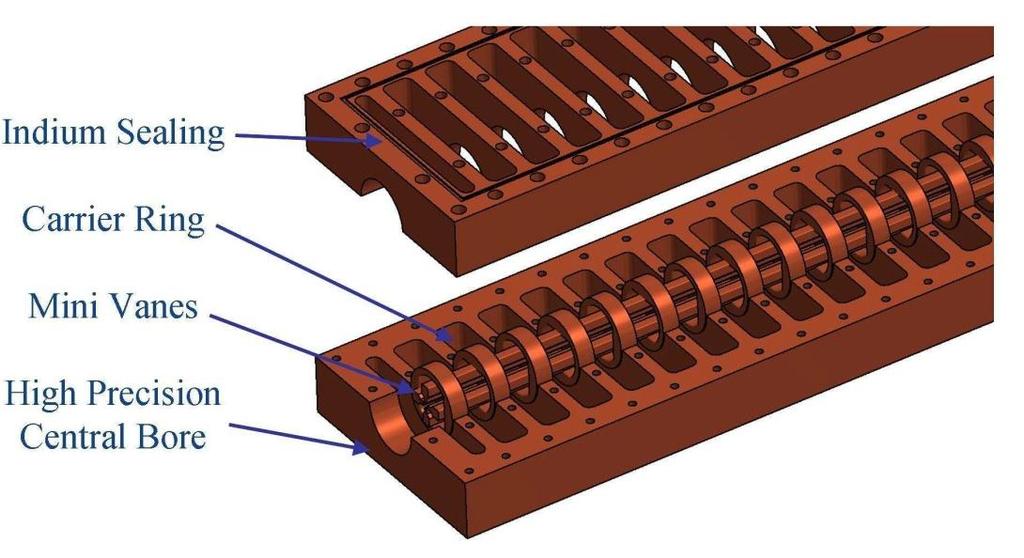
![4-Ladder-RFQ and 4-Rod-RFQ development at 325 MHz Table 1: Main parameters of the Ladder - RFQ No. of RF Cells 52 Energiy Gain [MeV] 0.95-3.](/docs-images/92/109105546/images/38-0.jpg "0 Q-Value (sim.) 8000 Frequency [MHz] 325.224 Stem Height [mm] 240 Stem Width [mm] 160 RF Cell Length [mm] 60 R. Brodhage, U. Ratzinger A.")
![Almomani, IPAC13, Shanghai 4-Rod-RFQ Type I Height beam axis [mm] 75 Stem width [mm] 100 RF cell length [mm] 50 Base plate height [mm] 12 Stem](/docs-images/92/109105546/images/38-1.jpg "arm width [mm] 10 Frequency[MHz] 307.5 Dipole 1%- range Frequency shift [MHz] 24,4 Q-value (sim.) 4100 B. Koubek, H. Podlech, J.S.")
38 4-Ladder-RFQ and 4-Rod-RFQ development at 325 MHz Table 1: Main parameters of the Ladder - RFQ No. of RF Cells 52 Energiy Gain [MeV] Q-Value (sim.) 8000 Frequency [MHz] Stem Height [mm] 240 Stem Width [mm] 160 RF Cell Length [mm] 60 R. Brodhage, U. Ratzinger A. Almomani, IPAC13, Shanghai 4-Rod-RFQ Type I Height beam axis [mm] 75 Stem width [mm] 100 RF cell length [mm] 50 Base plate height [mm] 12 Stem arm width [mm] 10 Frequency[MHz] Dipole 1%- range Frequency shift [MHz] 24,4 Q-value (sim.) 4100 B. Koubek, H. Podlech, J.S. Schmidt, IPAC13, Shanghai 38
39 4-Ladder-RFQ Geometric design parameters, dependence on frequency and Q-value 39


40 4-Ladder-RFQ Mechanical design studies at IAP Frankfurt 40
 41")
41 The European MYRRHA Project MYRRHA Project Multi-purpose hybrid Research Reactor for High-tech Applications At Mol (Belgium) 41

42 The European MYRRHA Project Layout of the 17 MeV section designed by IAP 42
43 Conclusions Many activities wordwide on linac development for fundamental research and for applications. Better performance of linac key components is one direction to go. Room temperature designs may gain attraction by new rf amplifier technology if pulsed beams are acceptable, rf duty factor up to 5%. FAIR Proton Injector development should demonstrate the capabilities of a novel approach. 43

44 Horst Klein, Celebration of his 80th Birthday 44
Development, construction and testing of a room temperature CH-DTL
 Development, construction and testing of a room temperature CH-DTL G.Clemente 1, H.Podlech 1, R. Tiede 1, U.Ratzinger 1, L.Groening 2, S.Minaev 3 1) Institute for Applied Physics, J.W. Goethe University,
Design of the linear accelerator for the MYRRHA project
 MYRRHA Multipurpose hybrid Research Reactor for High-tech Applications Design of the linear accelerator for the MYRRHA project Roberto Salemme ADT - Outline What is MYRRHA? MYRRHA accelerator: requirements
The sc cw-linac project TASCA2012, S. Mickat, LINAC
 The sc cw-linac project 14.09.2012 TASCA2012, S. Mickat, LINAC What is the status of the cw LINAC? 1. Motivation 2. HLI-Upgrade 3. cw-linac 4. cw-linac-demonstrator 5. Perspective of a cw-linac @GSI 6.
2 Work Package and Work Unit descriptions. 2.8 WP8: RF Systems (R. Ruber, Uppsala)
") 2 Work Package and Work Unit descriptions 2.8 WP8: RF Systems (R. Ruber, Uppsala) The RF systems work package (WP) addresses the design and development of the RF power generation, control and distribution
2 Work Package and Work Unit descriptions 2.8 WP8: RF Systems (R. Ruber, Uppsala) The RF systems work package (WP) addresses the design and development of the RF power generation, control and distribution
4.4 Injector Linear Accelerator
 4.4 Injector Linear Accelerator 100 MeV S-band linear accelerator based on the components already built for the S-Band Linear Collider Test Facility at DESY [1, 2] will be used as an injector for the CANDLE
RF plans for ESS. Morten Jensen. ESLS-RF 2013 Berlin
 RF plans for ESS Morten Jensen ESLS-RF 2013 Berlin Overview The European Spallation Source (ESS) will house the most powerful proton linac ever built. The average beam power will be 5 MW which is five
The PEFP 20-MeV Proton Linear Accelerator
 Journal of the Korean Physical Society, Vol. 52, No. 3, March 2008, pp. 721726 Review Articles The PEFP 20-MeV Proton Linear Accelerator Y. S. Cho, H. J. Kwon, J. H. Jang, H. S. Kim, K. T. Seol, D. I.
Upgrading LHC Luminosity
 1 Upgrading LHC Luminosity 2 Luminosity (cm -2 s -1 ) Present (2011) ~2 x10 33 Beam intensity @ injection (*) Nominal (2015?) 1 x 10 34 1.1 x10 11 Upgraded (2021?) ~5 x10 34 ~2.4 x10 11 (*) protons per
Proton Engineering Frontier Project
 Proton Engineering Frontier Project OECD Nuclear Energy Agency Fifth International Workshop on the Utilisation and Reliability of High Power Proton Accelerators (HPPA5) (6-9 May 2007, Mol, Belgium) Yong-Sub
INFN School on Electron Accelerators. RF Power Sources and Distribution
 INFN School on Electron Accelerators 12-14 September 2007, INFN Sezione di Pisa Lecture 7b RF Power Sources and Distribution Carlo Pagani University of Milano INFN Milano-LASA & GDE The ILC Double Tunnel
Detailed Design Report
 Detailed Design Report Chapter 4 MAX IV Injector 4.6. Acceleration MAX IV Facility CHAPTER 4.6. ACCELERATION 1(10) 4.6. Acceleration 4.6. Acceleration...2 4.6.1. RF Units... 2 4.6.2. Accelerator Units...
ESS: The Machine. Bucharest, 24 April Håkan Danared Deputy Head Accelerator Division. H. Danared Industry & Partner Days Bucharest Page 1
 ESS: The Machine Bucharest, 24 April 2014 Håkan Danared Deputy Head Accelerator Division H. Danared Industry & Partner Days Bucharest Page 1 2025 ESS construction complete 2009 Decision: ESS will be built
III. Proton-therapytherapy. Rome SB - 3/5 1
 Outline Introduction: an historical review I Applications in medical diagnostics Particle accelerators for medicine Applications in conventional radiation therapy II III IV Hadrontherapy, the frontier
The ESS Accelerator. For Norwegian Industry and Research. Oslo, 24 Sept Håkan Danared Deputy Head Accelerator Division Group Leader Beam Physics
 The ESS Accelerator For Norwegian Industry and Research Oslo, 24 Sept 2013 Håkan Danared Deputy Head Accelerator Division Group Leader Beam Physics The Hadron Intensity Frontier Courtesy of M. Seidel (PSI)
1.0 Abstract : 2.0 The drift tube Linac for LEHIPA
 Electromagnetic design and development of quadrupole focussing lenses for drift tube linac email : sanjaym@barc.gov.in Sanjay Malhotra, U.Mahapatra Control Instrumentation Division, Bhabha Atomic Research
The SPL at CERN. slhc. 1. Introduction 2. Description. 3. Status of the SPL study. - Stage 1: Linac4 - Stage 2: LP-SPL - Potential further stages
 The SPL at CERN 1. Introduction 2. Description - Stage 1: Linac4 - Stage 2: LP-SPL - Potential further stages 3. Status of the SPL study slhc Roa Garoby for the SPL team 1. Introduction Motivation for
PRESENT STATUS OF J-PARC
 PRESENT STATUS OF J-PARC # F. Naito, KEK, Tsukuba, Japan Abstract Japan Proton Accelerator Research Complex (J-PARC) is the scientific facility with the high-intensity proton accelerator aiming to realize
Linac 4 Instrumentation K.Hanke CERN
 Linac 4 Instrumentation K.Hanke CERN CERN Linac 4 PS2 (2016?) SPL (2015?) Linac4 (2012) Linac4 will first inject into the PSB and then can be the first element of a new LHC injector chain. It will increase
A HIGH POWER LONG PULSE HIGH EFFICIENCY MULTI BEAM KLYSTRON
 A HIGH POWER LONG PULSE HIGH EFFICIENCY MULTI BEAM KLYSTRON A.Beunas and G. Faillon Thales Electron Devices, Vélizy, France S. Choroba DESY, Hamburg, Germany Abstract THALES ELECTRON DEVICES has developed
DESIGN OF 1.2-GEV SCL AS NEW INJECTOR FOR THE BNL AGS*
 DESIGN OF 1.2-GEV SCL AS NEW INJECTOR FOR THE BNL AGS* A. G. Ruggiero, J. Alessi, M. Harrison, M. Iarocci, T. Nehring, D. Raparia, T. Roser, J. Tuozzolo, W. Weng. Brookhaven National Laboratory, PO Box
APT Accelerator Technology
 APT Accelerator Technology J. David Schneider LER/APT, Los Alamos National Laboratory Los Alamos, New Mexico 87545 U.S. Abstract The proposed accelerator production of tritium (APT) project requires an
A HIGH-POWER SUPERCONDUCTING H - LINAC (SPL) AT CERN
 AT CERN") A HIGH-POWER SUPERCONDUCTING H - LINAC (SPL) AT CERN E. Chiaveri, CERN, Geneva, Switzerland Abstract The conceptual design of a superconducting H - linear accelerator at CERN for a beam energy of 2.2 GeV
A HIGH-POWER SUPERCONDUCTING H - LINAC (SPL) AT CERN E. Chiaveri, CERN, Geneva, Switzerland Abstract The conceptual design of a superconducting H - linear accelerator at CERN for a beam energy of 2.2 GeV
RF considerations for SwissFEL
 RF considerations for H. Fitze in behalf of the PSI RF group Workshop on Compact X-Ray Free Electron Lasers 19.-21. July 2010, Shanghai Agenda Introduction RF-Gun Development C-band development Summary
Particle Beam Production - A Synchrotron-Based System - Prof. Dr. Thomas Haberer Scientific-technical Director Heidelberg Iontherapy Center
 Particle Beam Production - A Synchrotron-Based System - Prof. Dr. Thomas Haberer Scientific-technical Director Heidelberg Iontherapy Center Outline Situation/Rationale Requirements Synchrotron choice Functions
DELIVERY RECORD. Location: Ibaraki, Japan
 DELIVERY RECORD Client: Japan Atomic Energy Agency (JAEA) High Energy Accelerator Research Organization (KEK) Facility: J-PARC (Japan Proton Accelerator Research Complex) Location: Ibaraki, Japan 1 October
RUNNING EXPERIENCE OF FZD SRF PHOTOINJECTOR
 RUNNING EXPERIENCE OF FZD SRF PHOTOINJECTOR Rong Xiang On behalf of the BESSY-DESY-FZD-MBI collaboration and the ELBE team FEL 2009, Liverpool, United Kingdom, August 23 ~ 28, 2009 Outline Introduction
Diamond RF Status (RF Activities at Daresbury) Mike Dykes
 Mike Dykes") Diamond RF Status (RF Activities at Daresbury) Mike Dykes ASTeC What is it? What does it do? Diamond Status Linac Booster RF Storage Ring RF Summary Content ASTeC ASTeC was formed in 2001 as a centre of
Diamond RF Status (RF Activities at Daresbury) Mike Dykes ASTeC What is it? What does it do? Diamond Status Linac Booster RF Storage Ring RF Summary Content ASTeC ASTeC was formed in 2001 as a centre of
Experience with the Cornell ERL Injector SRF Cryomodule during High Beam Current Operation
 Experience with the Cornell ERL Injector SRF Cryomodule during High Beam Current Operation Matthias Liepe Assistant Professor of Physics Cornell University Experience with the Cornell ERL Injector SRF
3 cerl. 3-1 cerl Overview. 3-2 High-brightness DC Photocathode Gun and Gun Test Beamline
 3 cerl 3-1 cerl Overview As described before, the aim of the cerl in the R&D program includes the development of critical components for the ERL, as well as the construction of a test accelerator. The
Commissioning of Accelerators. Dr. Marc Munoz (with the help of R. Miyamoto, C. Plostinar and M. Eshraqi)
") Commissioning of Accelerators Dr. Marc Munoz (with the help of R. Miyamoto, C. Plostinar and M. Eshraqi) www.europeanspallationsource.se 6 July, 2017 Contents General points Definition of Commissioning
Commissioning of Accelerators Dr. Marc Munoz (with the help of R. Miyamoto, C. Plostinar and M. Eshraqi) www.europeanspallationsource.se 6 July, 2017 Contents General points Definition of Commissioning
Evaluation of Performance, Reliability, and Risk for High Peak Power RF Sources from S-band through X-band for Advanced Accelerator Applications
 Evaluation of Performance, Reliability, and Risk for High Peak Power RF Sources from S-band through X-band for Advanced Accelerator Applications Michael V. Fazio C. Adolphsen, A. Jensen, C. Pearson, D.
Karin Rathsman, Håkan Danared and Rihua Zeng. Report from RF Power Source Workshop
 Accelerator Division ESS AD Technical Note ESS/AD/0020 Karin Rathsman, Håkan Danared and Rihua Zeng Report from RF Power Source Workshop 10 July 2011 Report on the RF Power Source Workshop K. Rathsman,
HIGH-INTENSITY PROTON BEAMS AT CERN AND THE SPL STUDY
 HIGH-INTENSITY PROTON BEAMS AT CERN AND THE STUDY E. Métral, M. Benedikt, K. Cornelis, R. Garoby, K. Hanke, A. Lombardi, C. Rossi, F. Ruggiero, M. Vretenar, CERN, Geneva, Switzerland Abstract The construction
High Brightness Injector Development and ERL Planning at Cornell. Charlie Sinclair Cornell University Laboratory for Elementary-Particle Physics
 High Brightness Injector Development and ERL Planning at Cornell Charlie Sinclair Cornell University Laboratory for Elementary-Particle Physics June 22, 2006 JLab CASA Seminar 2 Background During 2000-2001,
ILC-LNF TECHNICAL NOTE
 IL-LNF EHNIAL NOE Divisione Acceleratori Frascati, July 4, 2006 Note: IL-LNF-001 RF SYSEM FOR HE IL DAMPING RINGS R. Boni, INFN-LNF, Frascati, Italy G. avallari, ERN, Geneva, Switzerland Introduction For
The FAIR plinac RF Systems
 The FAIR plinac RF Systems Libera Workshop Sep. 2011 Gerald Schreiber Gerald Schreiber, GSI RF Department 2 (1) Overview GSI / FAIR (2) FAIR Proton Linear Accelerator "plinac" (3) plinac RF Systems (4)
RF Solutions for Science.
 RF Solutions for Science www.thalesgroup.com State-of-the-art RF sources for your scientific needs High-power klystrons HIGH KLYSTRONS WITH RF LONG PULSE above 50 μs Thales has been one of the leading
DESIGN AND PERFORMANCE OF L-BAND AND S-BAND MULTI BEAM KLYSTRONS
 DESIGN AND PERFORMANCE OF L-BAND AND S-BAND MULTI BEAM KLYSTRONS Y. H. Chin, KEK, Tsukuba, Japan. Abstract Recently, there has been a rising international interest in multi-beam klystrons (MBK) in the
Summary of the 1 st Beam Line Review Meeting Injector ( )
") Summary of the 1 st Beam Line Review Meeting Injector (23.10.2006) 15.11.2006 Review the status of: beam dynamics understanding and simulations completeness of beam line description conceptual design of
Summary of the 1 st Beam Line Review Meeting Injector (23.10.2006) 15.11.2006 Review the status of: beam dynamics understanding and simulations completeness of beam line description conceptual design of
STATUS OF THE SWISSFEL C-BAND LINEAR ACCELERATOR
 Proceedings of FEL213, New York, NY, USA STATUS OF THE SWISSFEL C-BAND LINEAR ACCELERATOR F. Loehl, J. Alex, H. Blumer, M. Bopp, H. Braun, A. Citterio, U. Ellenberger, H. Fitze, H. Joehri, T. Kleeb, L.
Current status of XFEL/SPring-8 project and SCSS test accelerator
 Current status of XFEL/SPring-8 project and SCSS test accelerator Takahiro Inagaki for XFEL project in SPring-8 inagaki@spring8.or.jp Outline (1) Introduction (2) Key technology for compactness (3) Key
Introduction: CW SRF linac types, requirements and challenges High power RF system architecture
 RF systems for CW SRF linacs S. Belomestnykh Cornell University Laboratory for Elementary-Particle Physics LINAC08, Victoria, Canada October 1, 2008 Outline L band Introduction: CW SRF linac types, requirements
IOT OPERATIONAL EXPERIENCE ON ALICE AND EMMA AT DARESBURY LABORATORY
 IOT OPERATIONAL EXPERIENCE ON ALICE AND EMMA AT DARESBURY LABORATORY A. Wheelhouse ASTeC, STFC Daresbury Laboratory ESLS XVIII Workshop, ELLETRA 25 th 26 th November 2010 Contents Brief Description ALICE
The European Spallation Source
 The European Spallation Source Roger Ruber Uppsala University NIKHEF industriemiddag 21 september 2011 The European Spallation Source Roger Ruber - The European Spallation Source NIKHEF, 21-Sep-2011 page
L-Band RF R&D. SLAC DOE Review June 15 th, Chris Adolphsen SLAC
 L-Band RF R&D SLAC DOE Review June 15 th, 2005 Chris Adolphsen SLAC International Linear Collider (ILC) RF Unit (TESLA TDR Layout) Gradient = 23.4 MV/m Bunch Spacing = 337 ns Fill Time = 420 µs Train Length
Status of CTF3. G.Geschonke CERN, AB
 Status of CTF3 G.Geschonke CERN, AB CTF3 layout CTF3 - Test of Drive Beam Generation, Acceleration & RF Multiplication by a factor 10 Drive Beam Injector ~ 50 m 3.5 A - 2100 b of 2.33 nc 150 MeV - 1.4
RF Power Generation II
 RF Power Generation II Klystrons, Magnetrons and Gyrotrons Professor R.G. Carter Engineering Department, Lancaster University, U.K. and The Cockcroft Institute of Accelerator Science and Technology Scope
Tutorial: Trak design of an electron injector for a coupled-cavity linear accelerator
 Tutorial: Trak design of an electron injector for a coupled-cavity linear accelerator Stanley Humphries, Copyright 2012 Field Precision PO Box 13595, Albuquerque, NM 87192 U.S.A. Telephone: +1-505-220-3975
THE NEXT LINEAR COLLIDER TEST ACCELERATOR: STATUS AND RESULTS * Abstract
 SLAC PUB 7246 June 996 THE NEXT LINEAR COLLIDER TEST ACCELERATOR: STATUS AND RESULTS * Ronald D. Ruth, SLAC, Stanford, CA, USA Abstract At SLAC, we are pursuing the design of a Next Linear Collider (NLC)
Status of BESSY II and berlinpro. Wolfgang Anders. Helmholtz-Zentrum Berlin for Materials and Energy (HZB) 20th ESLS-RF Meeting
 20th ESLS-RF Meeting") Status of BESSY II and berlinpro Wolfgang Anders Helmholtz-Zentrum Berlin for Materials and Energy (HZB) 20th ESLS-RF Meeting 16.-17.11.2016 at PSI Outline BESSY II Problems with circulators Landau cavity
Status of BESSY II and berlinpro Wolfgang Anders Helmholtz-Zentrum Berlin for Materials and Energy (HZB) 20th ESLS-RF Meeting 16.-17.11.2016 at PSI Outline BESSY II Problems with circulators Landau cavity
Preparations for Installation, Testing and Commissioning based on Experience at CERN, SNS and Siemens
 Preparations for Installation, Testing and Commissioning based on Experience at CERN, SNS and Siemens Eugène Tanke FRIB / MSU ESS Seminar, Lund, 6 March 2013 Outline Project Goal for the Accelerator Path
THE OPERATION EXPERIENCE AT KOMAC*
 THAM2X01 Proceedings of HB2016, Malmö, Sweden THE OPERATION EXPERIENCE AT KOMAC* Yong-Sub Cho, Kye-Ryung Kim, Kui Young Kim, Hyeok-Jung Kwon, Han-Sung Kim, Young-Gi Song Korea Atomic Energy Research Institute,
Towards an X-Band Power Source at CERN and a European Structure Test Facility
 Towards an X-Band Power Source at CERN and a European Structure Test Facility Erk Jensen and Gerry McMomagle CERN The X-Band Accelerating Structure Design and Test-Program Workshop Day 2: Structure Testing
XFEL High Power RF System Recent Developments
 XFEL High Power RF System Recent Developments for the XFEL RF Group Outline XFEL RF System Requirements Overview Basic Layout RF System Main Components Multibeam Klystrons Modulator RF Waveguide Distribution
The Construction Status of CSNS Linac
 The Construction Status of CSNS Linac Sheng Wang Dongguan branch, Institute of High Energy Physics, CAS Sep.2, 2014, Geneva Outline The introduction to CSNS accelerators The commissoning of ion source
45 MW, 22.8 GHz Second-Harmonic Multiplier for High-Gradient Tests*
 US High Gradient Research Collaboration Workshop. SLAC, May 23-25, 2007 45 MW, 22.8 GHz Second-Harmonic Multiplier for High-Gradient Tests* V.P. Yakovlev 1, S.Yu. Kazakov 1,2, and J.L. Hirshfield 1,3 1
IOT RF Power Sources for Pulsed and CW Linacs
 LINAC 2004 Lübeck, August 16 20, 2004 IOT RF Power Sources H. Bohlen, Y. Li, Bob Tornoe Communications & Power Industries Eimac Division, San Carlos, CA, USA Linac RF source property requirements (not
PEP II Design Outline
 PEP II Design Outline Balša Terzić Jefferson Lab Collider Review Retreat, February 24, 2010 Outline General Information Parameter list (and evolution), initial design, upgrades Collider Ring Layout, insertions,
The Elettra Storage Ring and Top-Up Operation
 The Elettra Storage Ring and Top-Up Operation Emanuel Karantzoulis Past and Present Configurations 1994-2007 From 2008 5000 hours /year to the users 2010: Operations transition year Decay mode, 2 GeV (340mA)
The LEP Superconducting RF System
 The LEP Superconducting RF System K. Hübner* for the LEP RF Group CERN The basic components and the layout of the LEP rf system for the year 2000 are presented. The superconducting system consisted of
Development of High Power Vacuum Tubes for Accelerators and Plasma Heating
 Development of High Power Vacuum Tubes for Accelerators and Plasma Heating Vishnu Srivastava Microwave Tubes Division, CSIR-Central Electronics Engineering Research Institute, Pilani-333031, Rajasthan,
!"!3
 Abstract A single-mode 500 MHz superconducting cavity cryomodule has been developed at Cornell for the electronpositron collider/synchrotron light source CESR. The Cornell B-cell cavity belongs to the
CLIC Feasibility Demonstration at CTF3
 CLIC Feasibility Demonstration at CTF3 Roger Ruber Uppsala University, Sweden, for the CLIC/CTF3 Collaboration http://cern.ch/clic-study LINAC 10 MO303 13 Sep 2010 The Key to CLIC Efficiency NC Linac for
NEW METHOD FOR KLYSTRON MODELING
 NEW METHOD FOR KLYSTRON MODELING Y. H. Chin, KEK, 1-1 Oho, Tsukuba-shi, Ibaraki-ken, 35, Japan Abstract We have developed a new method for a realistic and more accurate simulation of klystron using the
SRF-gun Development Overview. J. Sekutowicz 17 th September, 2015 SRF15, Whistler, Canada
 SRF-gun Development Overview J. Sekutowicz 17 th September, 2015 SRF15, Whistler, Canada Acknowledgment Many thanks to: A. Arnold, J. Hao, E. Kako, T. Konomi, D. Kostin, J. Lorkiewicz, A. Neumann, J. Teichert
Final Report. U.S. Department of Energy Grant Number DE-FG02-04ER83916
 Development of a 200 MHz Multiple Beam Klystron Final Report U.S. Department of Energy Grant Number DE-FG02-04ER83916 July 2004 - March 2005 Calabazas Creek Research, Inc. 20937 Comer Drive Saratoga, CA
KARA and FLUTE RF Overview/status
 KARA and FLUTE RF Overview/status Nigel Smale on behalf of IBPT and LAS teams Laboratory for Applications of Synchrotron radiation (LAS) Institute for Beam Physics and Technology (IBPT) KARA KIT The Research
A Brief History of High Power RF Proton Linear Accelerators
 e A Brief History of High Power RF Proton Linear Accelerators John C. Browne Los Alamos National Laboratory Introduction The first mention of linear acceleration was in a paper by G. Ising in 1924 (Ref
STATUS OF THE SwissFEL C-BAND LINAC
 STATUS OF THE SwissFEL C-BAND LINAC F. Loehl, J. Alex, H. Blumer, M. Bopp, H. Braun, A. Citterio, U. Ellenberger, H. Fitze, H. Joehri, T. Kleeb, L. Paly, J.-Y. Raguin, L. Schulz, R. Zennaro, C. Zumbach,
Technology Challenges for SRF Guns as ERL Sources in View of Rossendorf work
 Technology Challenges for SRF Guns as ERL Sources in View of Rossendorf work, Hartmut Buettig, Pavel Evtushenko, Ulf Lehnert, Peter Michel, Karsten Moeller, Petr Murcek, Christof Schneider, Rico Schurig,
Oak Ridge Spallation Neutron Source Proton Power Upgrade Project and Second Target Station Project
 Oak Ridge Spallation Neutron Source Proton Power Upgrade Project and Second Target Station Project Workshop on the future and next generation capabilities of accelerator driven neutron and muon sources
TESLA FEL-Report
 Determination of the Longitudinal Phase Space Distribution produced with the TTF Photo Injector M. Geitz a,s.schreiber a,g.von Walter b, D. Sertore a;1, M. Bernard c, B. Leblond c a Deutsches Elektronen-Synchrotron,
High Rep Rate Guns: FZD Superconducting RF Photogun
 High Rep Rate Guns: FZD Superconducting RF Photogun J. Teichert, A. Arnold, H. Büttig, D. Janssen, M. Justus, U. Lehnert, P. Michel, K. Moeller, P. Murcek, Ch. Schneider, R. Schurig, G. Staats, F. Staufenbiel,
Pulsed Klystrons for Next Generation Neutron Sources Edward L. Eisen - CPI, Inc. Palo Alto, CA, USA
 Pulsed Klystrons for Next Generation Neutron Sources Edward L. Eisen - CPI, Inc. Palo Alto, CA, USA Abstract The U.S. Department of Energy (DOE) Office of Science has funded the construction of a new accelerator-based
TITLE PAGE. Title of paper: PUSH-PULL FEL, A NEW ERL CONCEPT Author: Andrew Hutton. Author Affiliation: Jefferson Lab. Requested Proceedings:
 TITLE PAGE Title of paper: PUSH-PULL FEL, A NEW ERL CONCEPT Author: Andrew Hutton Author Affiliation: Jefferson Lab Requested Proceedings: Unique Session ID: Classification Codes: Keywords: Energy Recovery,
A New High Intensity Proton Source. The SCRF Proton Driver. (and more!) at Fermilab. July 15, Bill Foster SRF2005
 at Fermilab. July 15, Bill Foster SRF2005") The SCRF Proton Driver A New High Intensity Proton Source (and more!) at Fermilab Bill Foster SRF2005 July 15, 2005 Outline The Concept Fermilab Strategic Context Proton Driver SRF Linac Design Ferrite
The SCRF Proton Driver A New High Intensity Proton Source (and more!) at Fermilab Bill Foster SRF2005 July 15, 2005 Outline The Concept Fermilab Strategic Context Proton Driver SRF Linac Design Ferrite
Studies on an S-band bunching system with hybrid buncher
 Submitted to Chinese Physics C Studies on an S-band bunching system with hybrid buncher PEI Shi-Lun( 裴士伦 ) 1) XIAO Ou-Zheng( 肖欧正 ) Institute of High Energy Physics, Chinese Academy of Sciences, Beijing
Dark current and multipacting trajectories simulations for the RF Photo Gun at PITZ
 Dark current and multipacting trajectories simulations for the RF Photo Gun at PITZ Introduction The PITZ RF Photo Gun Field simulations Dark current simulations Multipacting simulations Summary Igor Isaev
DARK CURRENT IN SUPERCONDUCTING RF PHOTOINJECTORS MEASUREMENTS AND MITIGATION
 DARK CURRENT IN SUPERCONDUCTING RF PHOTOINJECTORS MEASUREMENTS AND MITIGATION J. Teichert #, A. Arnold, P. Murcek, G. Staats, R. Xiang, HZDR, Dresden, Germany P. Lu, H. Vennekate, HZDR & Technische Universität,
ESS Linac WP8 Radio Frequency Systems and Test Facilities
 ESS Linac WP8 Radio Frequency Systems and Test Facilities ESS/SPL Collaboration Meeting Lund, 29 June 2010 Roger Ruber (Uppsala University) for the ESS Linac RF Team ESS Linac WP8: RF Systems Outline Work
Development of Multiple Beam Guns for High Power RF Sources for Accelerators and Colliders
 SLAC-PUB-10704 Development of Multiple Beam Guns for High Power RF Sources for Accelerators and Colliders R. Lawrence Ives*, George Miram*, Anatoly Krasnykh @, Valentin Ivanov @, David Marsden*, Max Mizuhara*,
Performance of a DC GaAs photocathode gun for the Jefferson lab FEL
 Nuclear Instruments and Methods in Physics Research A 475 (2001) 549 553 Performance of a DC GaAs photocathode gun for the Jefferson lab FEL T. Siggins a, *, C. Sinclair a, C. Bohn b, D. Bullard a, D.
TECHNICAL SPECIFICATION Multi-beam S-band Klystron type BT267
 TECHNICAL SPECIFICATION Multi-beam S-band Klystron type BT267 The company was created for the development and manufacture of precision microwave vacuum-electron-tube devices (VETD). The main product areas
RF Design of the LCLS Gun C.Limborg, Z.Li, L.Xiao, J.F. Schmerge, D.Dowell, S.Gierman, E.Bong, S.Gilevich February 9, 2005
 RF Design of the LCLS Gun C.Limborg, Z.Li, L.Xiao, J.F. Schmerge, D.Dowell, S.Gierman, E.Bong, S.Gilevich February 9, 2005 Summary Final dimensions for the LCLS RF gun are described. This gun, referred
OPERATIONAL EXPERIENCE AT J-PARC
 OPERATIONAL EXPERIENCE AT J-PARC Hideaki Hotchi, ) for J-PARC commissioning team ), 2), ) Japan Atomic Energy Agency (JAEA), Tokai, Naka, Ibaraki, 39-95 Japan, 2) High Energy Accelerator Research Organization
TOSHIBA Industrial Magnetron E3328
 TOSHIBA E3328 is a fixed frequency continuous wave magnetron intended for use in the industrial microwave heating applications. The average output power is 3kW in the frequency range from 2450 to 2470
Production of accelerators and accelerator components in industry
 Production of accelerators and accelerator components in industry Michael Pekeler RI Research Instruments GmbH Friedrich-Ebert-Str. 1 51429 Bergisch Gladbach 28.04.2009 Foundation of RI Research Instruments
ADVANCED HIGH-POWER MICROWAVE VACUUM ELECTRON DEVICE DEVELOPMENT
 ADVANCED HIGH-POWER MICROWAVE VACUUM ELECTRON DEVICE DEVELOPMENT H. P. Bohlen, Inc., Palo Alto, CA Abstract The microwave 1 power requirements of particle accelerators have been growing almost exponentially
Karin Rathsman. Calculations on the RF Source and Distribution
 Accelerator Division ESS AD Technical Note ESS/AD/0002 Karin Rathsman Calculations on the RF Source and Distribution 26 March 2010 Calculations on the rf source and distribution system for the ESS elliptical
Nick Walker DESY MAC
 Nick Walker DESY MAC 4.5.2006 XFEL X-Ray Free-Electron Laser DESY ILC Project Group Accelerator Experimentation Behnke, Elsen, Walker (chair) WP 15, 16 WP 4-7 Accelerator Physics and Design WP 6 High Gradient
30 GHz Power Production / Beam Line
 30 GHz Power Production / Beam Line Motivation & Requirements Layout Power mode operation vs. nominal parameters Beam optics Achieved performance Problems Beam phase switch for 30 GHz pulse compression
Empirical Model For ESS Klystron Cathode Voltage
 Empirical Model For ESS Klystron Cathode Voltage Dave McGinnis 2 March 2012 Introduction There are 176 klystrons in the superconducting portion of ESS linac. The power range required spans a factor of
SUMMARY OF THE ILC R&D AND DESIGN
 SUMMARY OF THE ILC R&D AND DESIGN B. C. Barish, California Institute of Technology, USA Abstract The International Linear Collider (ILC) is a linear electron-positron collider based on 1.3 GHz superconducting
An Optimised Design for the Linac4 Drift Tube Linac
 An Optimised Design for the Linac4 Drift Tube Linac S. Ramberger, P. Bourquin, Y. Cuvet, G. De Michele, F. Gerigk, J.-M. Giguet, A.M. Lombardi, E. Sargsyan, M. Vretenar CERN, Geneva, Switzerland Abstract
ESS Linac WP8 Radio Frequency Systems and Test Facilities
 ESS Linac WP8 Radio Frequency Systems and Test Facilities ESS TAC Lund, 8 July 2010 Roger Ruber (Uppsala University) for the ESS Linac RF Team Outline Work Package description Objectives Organization Technical
Design, Fabrication and Testing of Gun-Collector Test Module for 6 MW Peak, 24 kw Average Power, S-Band Klystron
 Available online www.ejaet.com European Journal of Advances in Engineering and Technology, 2014, 1(1): 11-15 Research Article ISSN: 2394-658X Design, Fabrication and Testing of Gun-Collector Test Module
Linac upgrade plan using a C-band system for SuperKEKB
 Linac upgrade plan using a C-band system for SuperKEKB S. Fukuda, M. Akemono, M. Ikeda, T. Oogoe, T. Ohsawa, Y. Ogawa, K. Kakihara, H. Katagiri, T. Kamitani, M. Sato, T. Shidara, A. Shirakawa, T. Sugimura,
EPJ Web of Conferences 95,
 EPJ Web of Conferences 95, 04012 (2015) DOI: 10.1051/ epjconf/ 20159504012 C Owned by the authors, published by EDP Sciences, 2015 The ELENA (Extra Low Energy Antiproton) project is a small size (30.4
ACCELERATOR R&D FOR THE EUROPEAN ADS DEMONSTRATOR*
 ACCELERATOR R&D FOR THE EUROPEAN ADS DEMONSTRATOR* J-L. Biarrotte #, F. Bouly, S. Bousson, T. Junquera, A.C. Mueller, G. Olry, E. Rampnoux (CNRS, IPN Orsay), R. Gobin, M. Luong, D. Uriot (CEA Saclay),
STATUS OF THE INTERNATIONAL LINEAR COLLIDER
 STATUS OF THE INTERNATIONAL LINEAR COLLIDER K. Yokoya, KEK, Tsukuba, Japan Abstract The International Linear Collider (ILC) is the nextgeneration electron-positron collider. Since the publication of the