3AH3 Vacuum Circuit-Breakers
|
|
|
- Jonah Andrews
- 5 years ago
- Views:
Transcription


1 Catalog HG Edition AH3 Vacuum Circuit-Breakers Medium-Voltage Equipment siemens.com/3ah3

2 2 3AH3 Vacuum Circuit-Breakers Siemens HG R-HG tif
3 Contents 3AH3 Vacuum Circuit-Breakers Medium-Voltage Equipment Catalog HG Invalid: Catalog HG Contents Page Description 5 General 6 Construction and mode of operation, standards, maintenance-free design 7 Ambient conditions, current carrying capacity, dielectric strength 9 Basic equipment and product range overview 10 The three-circuit-breaker-solution for phase-segregated design 12 Equipment Selection 13 Order number structure and configuration example 14 Selection of basic types, high-current circuit-breakers (circuit-breakers according to IEC ) 15 Selection of basic types, generator circuit-breakers according to IEC / IEEE Selection of secondary equipment 19 Selection of additional equipment 27 Accessories and spare parts Technical Data 33 Electrical data, dimensions, weights and dimension drawings circuit-breakers according to IEC Electrical data, dimensions, weights and dimension drawings high-current and generator circuit-breakers according to IEC/IEEE Circuit diagrams 50 Operating times, short-circuit protection of motors, consumption data of releases 52 3 Annex 53 Inquiry form 54 Configuration instructions 55 Configuration aid Foldout page 4 The products and systems described in this catalog are manufactured and sold according to a certified management system (acc. to ISO 9001, ISO and BS OHSAS 18001). 3AH3 Vacuum Circuit-Breakers Siemens HG

4 4 3AH3 Vacuum Circuit-Breakers Siemens HG R-HG tif

5 Description Contents Contents Page Description 5 General 6 1 Construction and mode of operation 7 Switching medium 7 Pole assemblies 7 Operating mechanism box 7 Operating mechanism 7 Trip-free mechanism 7 Releases 8 Closing 8 Circuit-breaker tripping signal 8 Interlocking 8 Industrial application: Refinery R-HG tif Standards 8 Maintenance-free design 8 Ambient conditions, current carrying capacity and dielectric strength 9 Basic equipment and product range overview 10 The three-circuit-breaker-solution for phase-segregated design 12 3AH3 Vacuum Circuit-Breakers Siemens HG


6 Description General 1 3AH3 vacuum circuit-breaker from 7.2 kv to 36 kv The Powerful Circuit-breakers must make and break all currents within the scope of their ratings: From small inductive and capacitive load currents up to high short-circuit currents, controlling all fault conditions in the power system at the same time. 3AH3 maintenance-free for high switching capacities 3AH3 6 / 7 / 8 especially developed for generator applications R-HG tif R_HG11_218.tif The 3AH3 vacuum circuit-breaker is maintenance-free throughout its entire service life. It is extremely powerful and controls up to 10,000 operating cycles. This circuit-breaker is used, for example in industrial applications with high load currents up to 6300 A and high short-circuit currents up to 72 ka, covering the usual medium-voltage range from 7.2 to 40.5 kv. Due to its high performance, the circuit-breaker is also perfectly suitable for generator operation. For this purpose, these generator circuit-breakers are not only subjected to the basic type tests according to IEC , but also to the additional tests according to IEC / IEEE This international standard takes into account the increased requirements to which equipment is subjected when switching generators. As a result, it has also become the leading standard for generator circuit-breakers in IEC-oriented professional circles. Standard IEC/IEEE includes in particular: For generator-supplied faults: High DC components and the resulting missing current zeros For system-supplied faults: Higher TRV rates of rise Higher test voltage levels. For connection of larger generators, so-called phasesegregated generator switchgear is used, in which the single phases are accommodated in separate enclosures. For this application, generator circuit-breakers are equipped, tested and adjusted for parallel operation. In this way, even higher short-circuit currents up to 90 ka and normal currents up to 12,000 A can be switched. 6 3AH3 Vacuum Circuit-Breakers Siemens HG
. The switching movement is transferred by means of operating rods (4) and levers.")
 and the interrupter supports. The vacuum interrupters are air-insulated and freely accessible.")
, allowing axial movement.")
7 Description Construction and mode of operation The vacuum circuit-breaker consists of the pole assemblies (1) and the operating mechanism box (2). The pole assemblies are fixed to the operating mechanism box via post insulators (3). The switching movement is transferred by means of operating rods (4) and levers. 1 Switching medium The vacuum switching technology, proven and fully developed for more than 40 years, serves as arc-quenching principle by using vacuum interrupters. Pole assemblies The pole assemblies consist of the vacuum interrupters (6) and the interrupter supports. The vacuum interrupters are air-insulated and freely accessible. This makes it possible to clean the insulating parts easily in adverse ambient conditions. The vacuum interrupter is mounted rigidly to the upper interrupter support (5). The lower part of the interrupter is guided in the lower interrupter support (7), allowing axial movement. The braces absorb the external forces resulting from switching operations and the contact pressure. Operating mechanism box Circuit-breaker structure 1 Pole assembly 2 Operating mechanism box 3 Post insulator 4 Operating rod 5 Upper interrupter support 6 Vacuum interrupter 7 Lower interrupter support The whole operating mechanism with releases, auxiliary switches, indicators and actuating devices is accommodated in the operating mechanism box. The extent of the secondary equipment depends on the case of application and offers a multiple variety of options in order to meet almost every requirement. Operating mechanism The operating mechanism is a stored-energy mechanism. The closing spring is charged either electrically or manually. It latches tight at the end of the charging process and serves as an energy store. The force is transmitted from the operating mechanism to the pole assemblies via operating rods. To close the breaker, the closing spring can be unlatched either mechanically by means of the local ON pushbutton or electrically by remote control. The closing spring charges the opening or contact pressure springs as the breaker closes. The now discharged closing spring will be charged again automatically by the mechanism motor or manually. Then the operating sequence OPEN-CLOSE-OPEN is stored in the springs. The charging state of the closing spring can be checked electrically by means of a position switch. Trip-free mechanism 3AH3 vacuum circuit-breakers have a trip-free mechanism according to IEC In the event of an opening command being given after a closing operation has been initiated, the moving contacts return to the open position and remain there even if the closing command is sustained. This means that the contacts of the vacuum circuit-breakers are momentarily in the closed position, which is permissible according to IEC Front view Open operating mechanism box R-HG tif R-HG tif 3AH3 Vacuum Circuit-Breakers Siemens HG
8 Description Construction and mode of operation, standards, maintenance-free design 1 Releases A release is a device which transfers electrical commands from an external source, such as a control room, to the latching mechanism of the vacuum circuit-breaker so that it can be opened or closed. Apart from the closing solenoid, the maximum possible equipment is one shunt release and two other releases. For release combinations, refer to page 19. The closing solenoid unlatches the charged closing spring of the vacuum circuit-breaker, closing it by electrical means. It is suitable for DC or AC voltage. Shunt releases are used for automatic tripping of vacuum circuit-breakers by suitable protection relays and for deliberate tripping by electrical means. They are intended for connection to an external power supply (DC or AC voltage) but, in special cases, may also be connected to a voltage transformer for manual operation. Current-transformer operated releases comprise a storedenergy mechanism, an unlatching mechanism and an electromagnetic system. They are used when there is no external source of auxiliary power (e.g. a battery). Tripping is effected by means of a protection relay (e.g. overcurrenttime protection) acting on the current-transformer operated release. When the tripping current is exceeded (= 90 % of the rated normal current of the c.t.-operated release), the latch of the energy store, and thus opening of the circuit-breaker, is released. Undervoltage releases comprise a stored-energy mechanism, an unlatching mechanism and an electromagnetic system which is permanently connected to the secondary or auxiliary voltage while the vacuum circuit-breaker is closed. If the voltage falls below a predetermined value, unlatching of the release is enabled and the circuit-breaker is opened via the stored-energy mechanism. The deliberate tripping of the undervoltage release generally takes place via an NC contact in the tripping circuit or via an NO contact by short-circuiting the magnet coil. With this type of tripping, the short-circuit current is limited by the built-in resistors. Undervoltage releases can also be connected to voltage transformers. When the operating voltage drops to impermissibly low levels, the circuit-breaker is tripped automatically. For delayed tripping, the undervoltage release can be combined with energy stores. Closing In the standard version, 3AH3 vacuum circuit-breakers can be remote-closed electrically. They can also be closed locally by mechanical unlatching of the closing spring via pushbutton. Instead of this manual mechanical closing, manual electrical closing is also available. In this version, the closing circuit of the circuit-breaker is controlled electrically by a pushbutton instead of the mechanical button. In this way, switchgear-related interlocks can also be considered for local operation in order to prevent involuntary closing. If constant CLOSE and OPEN commands are present at the circuit-breaker at the same time, the circuit-breaker will return to the open position after closing. It remains in this position until a new CLOSE command is given. In this manner, continuous closing and opening (= pumping ) is prevented. Circuit-breaker tripping signal The NO contact makes brief contact while the vacuum circuit-breaker is opening, and this is often used to operate a hazard-warning system which, however, is only allowed to respond to automatic tripping of the circuit-breaker. Therefore, the signal from the NO contact must be interrupted when the circuit-breaker is being opened intentionally. This is accomplished under local control with the cut-out switch that is connected in series with the NO contact. Interlocking Electrical interlocking The circuit-breakers can be integrated in electromagnetic feeder or switchgear interlocks. In case of electrical interlocking, the disconnector or its operating mechanism is equipped with a magnetic lock-out mechanism. This mechanism is controlled by an auxiliary contact of the circuit-breaker, so that the disconnector can only be operated when the circuitbreaker is open. On the other hand, the circuit-breaker is also controlled by the disconnector or its operating mechanism, so that it can only be closed when the disconnector is in an end position. For this purpose, manual electrical closing must be provided in the circuit-breaker operating mechanism (see Closing ). Mechanical interlocking To interlock circuit-breaker trucks, withdrawable parts or disconnectors according to the switch position, the circuitbreakers can be equipped with a mechanical interlocking. A sensor at the switchgear checks the position of the circuitbreaker and prevents the open circuit-breaker in a reliable way from being closed mechanically and electrically. Standards 3AH3 circuit-breakers conform to the following standards: IEC IEC VDE 0671 IEC/IEEE :2015 (only generator circuitbreaker). All 3AH3 vacuum circuit-breakers fulfil the endurance classes E2, M2, C2 and S1 according to IEC Maintenance-free design The 3AH3 vacuum circuit-breakers are maintenance-free: Under normal ambient conditions according to IEC Up to 10,000 operating cycles, no relubrication, no readjustment required and within their tolerances, the characteristics are independent of the switching rate or of standing times without switching operations. 8 3AH3 Vacuum Circuit-Breakers Siemens HG
9 Description Ambient conditions, current carrying capacity and dielectric strength Ambient conditions The vacuum circuit-breakers are designed for the normal operating conditions defined in IEC Condensation can occasionally occur under the ambient conditions shown opposite. 3AH3 vacuum circuit-breakers are suitable for use in the following climatic classes according to IEC 60721, Part 3-3: 40 C 1 Climatic ambient conditions: Class 3K4 1) Biological ambient conditions: Class 3B1 Mechanical ambient conditions: Class 3M2 Chemically-active substances: Class 3C2 2) Mechanically-active substances: Class 3S2 3) 1) Low temperature limit: 5 C 2) Without icing and wind-driven precipitation 3) Restriction: Clean insulation parts Current carrying capacity -5 C max. 95% per day max. 90% per month HG a_en eps The rated normal currents specified in the opposite diagram have been defined according to IEC for an ambient air temperature of + 40 C and apply to open switchgear. For enclosed switchgear the data of the switchgear manufacturer applies. At ambient air temperatures below + 40 C, higher normal currents can be carried (see diagram): Characteristics curve 1 = Rated normal current 1250 A Characteristics curve 2 = Rated normal current 2000 A Characteristics curve 3 = Rated normal current 2500 A Characteristics curve 4 = Rated normal current 3150 A Characteristics curve 5 = Rated normal current 4000 A Characteristics curve 6 = Rated normal current 5000 A Characteristics curve 7 = Rated normal current 6300 A Rated normal current 7000 A HG c_en eps Dielectric strength The dielectric strength of air insulation decreases with increasing altitude due to low air density. According to IEC , the values of the rated lightning impulse withstand voltage and the rated short-duration power-frequency withstand voltage specified in the chapter Technical Data apply to a site altitude of 1000 m above sea level. For an altitude above 1000 m, the insulation level must be corrected according to the opposite diagram. The characteristic shown applies to both rated withstand voltages. To select the devices, the following applies: U U 0 x K a U Rated withstand voltage under reference atmosphere U 0 Rated withstand voltage requested for the place of installation K a Altitude correction factor according to the opposite diagram Altitude correction factor Ka C 70 Ambient air temperature HG c_en eps Example For a requested rated lightning impulse withstand voltage of 75 kv at an altitude of 2500 m, an insulation level of 90 kv under reference atmosphere is required as a minimum: Site altitude H 90 kv 75 kv x 1.2 3AH3 Vacuum Circuit-Breakers Siemens HG
10 Description Basic equipment and product range overview 1 Basic equipment Features Minimum equipment Alternative equipment Remarks Operating mechanism Closing Electrical operating mechanism (hand crank not included in the scope of supply) Closing solenoid and manual mechanical closing Manual operating mechanism (hand crank included in the scope of supply) Manual electrical closing 1 st release Shunt release None 2 nd release Without Shunt release, undervoltage release, c.t.-operated release 3 rd release Without Shunt release, undervoltage release, c.t.-operated release Varistor protection circuit Generally installed for DC 60 V Auxiliary switch 6 NO + 6 NC 12 NO + 12 NC Plug connector 24-pole terminal strip 24-pole plug, 64-pole plug Anti-pumping Available None Circuit-breaker Available None tripping signal Operating cycle counter Available None Spring charged Available None signal and indication Interlocking Without Mechanical interlocking None Hand crank available as accessory Max. 3 releases can be combined (for possible combinations, refer to page 19) Max. 3 releases can be combined (for possible combinations, refer to page 19) For limiting switching overvoltages due to inductive loads For the endurance class C2, all circuit-breakers fulfil the following values according to IEC Rated voltage U r kv, r.m.s. Line Cable Single capacitor bank Back-to-back capacitor bank 1) Rated line-charging breaking current I l A, r.m.s. Rated cable-charging breaking current I c A, r.m.s. Rated single capacitor bank breaking current 2) I sb A, r.m.s. Rated back-to-back capacitor bank breaking current I bb A, r.m.s. Frequency of the inrush current f bl Hz 1) Rated back-to-back capacitor bank making current for a back-to-back capacitor bank see chapter 3: Technical data 2) The capacitive switching capacity of the circuit-breaker is 0.7 x I r above the standard specification Product range overview for 3AH3 IEC high-current circuit-breakers Rated voltage Rated short-circuit breaking current Rated normal current (A) Pole-centre distance (mm) kv ka Available design 10 3AH3 Vacuum Circuit-Breakers Siemens HG


11 Description Basic equipment and product range overview Vacuum circuit-breaker for generator switching applications according to IEC/IEEE Type tests as specified in IEC are performed as a rule for all Siemens circuit-breakers. The generator circuit-breakers are additionally tested according to IEC/IEEE Standard IEC/IEEE includes in particular: For generator-supplied faults: High DC components and the resulting missing current zeroes For system-supplied faults: Higher TRV rates of rise Higher test voltage levels. 1 R_HG11_220.tif 3AH3 vacuum circuit-breaker Product range overview for 3AH37/3AH38 high-current and generator circuit-breakers (acc. to IEC/IEEE ) Rated voltage kv Rated short-circuit breaking current ka Rated normal current (A) forced cooling PMA 275 mm PMA 300 mm 3AH3 Vacuum Circuit-Breakers Siemens HG

 [ka] 50 63 72 80 90 80 100 DC component of the")
![rated short-circuit breaking current [%] 75 70 70 70 45 70 75 Asymmetrical breaking current [ka] 73 89 101 113 107 113 146 Rated short-circuit making current [ka] 137 173 197 219 247 219 274](/docs-images/87/95888221/images/12-3.jpg "Generator short-circuit breaking current I SC gen [ka] 25 31.")
![5 36 40 45 40 63 DC component of the short-circuit breaking current [%] 130 130 130 130 110 130 130 Asymmetrical breaking current [ka] 52 66 75 84 83 84 132 Rated voltage 17.](/docs-images/87/95888221/images/12-4.jpg "5 kv (IEC/IEEE 62271-37-013) U p = 110 kv, U d = 50 kv 24 kv (IEC 62271, IEC/IEEE 62271-37-013) U p = 125 kv, U d = 60 kv 3AH3732 3AH3733 3AH3734 3AH3735 3AH3756 3AH3615 3AH3617 3AH3742 3AH3743")
12 Description The three-circuit-breaker-solution for phase-segregated design 1 The three-circuit-breaker-solution for phase-segregated design For generator switchgear with segregated phases, one switching device is used per phase. The requirements for the simultaneity of poles are implemented according to IEC R-HG tif R-HG tif Technical data for phase-segregated design For the three-circuit-breaker-solution, three circuit-breakers are used which are optimized for interconnected operation. Complete module with integrated disconnector, earthing switch and start-up disconnector for each phase Rated short-circuit breaking current I SC (3s) [ka] DC component of the rated short-circuit breaking current [%] Asymmetrical breaking current [ka] Rated short-circuit making current [ka] Generator short-circuit breaking current I SC gen [ka] DC component of the short-circuit breaking current [%] Asymmetrical breaking current [ka] Rated voltage 17.5 kv (IEC/IEEE ) U p = 110 kv, U d = 50 kv 24 kv (IEC 62271, IEC/IEEE ) U p = 125 kv, U d = 60 kv 3AH3732 3AH3733 3AH3734 3AH3735 3AH3756 3AH3615 3AH3617 3AH3742 3AH3743 3AH3744 3AH3745 3AH3625 3AH3627 Rated normal currents [A] 4000 to 12,500 (depending on version) Rated operating sequence For short-circuit breaking current CO 30 min CO, up to 30 short-circuit breaking operations For normal current O 3 min CO 3 min CO, up to 10,000 operating cycles U p = Rated lightning impulse withstand voltage U d = Rated short-duration power-frequency withstand voltage For more detailed information on Phase-segregated design, we recommend the brochure Vacuum Circuit-Breakers for Generator Switching Applications. Please contact our Customer Support! Our experts will be pleased to assist you in finding the proper circuit-breaker for your generator switching application. R-HG tif R-HG tif R-HG tif The version with one switching device per phase is highly beneficial especially for flexible operation in retrofit or modernization projects. Example for retrofit installation: Replacement of compressed-air generator circuit-breakers (6 kv 86.5 ka 3500 A). With the generator switching module 3AH36, the HB3 is the world s first generator switchgear using vacuum switching technology rated up to 12,500 A, with natural cooling and 100 ka switching capacity, type-tested according to IEC/IEEE standard. 12 3AH3 Vacuum Circuit-Breakers Siemens HG
 Voltage level 7.2 kv 15 Voltage level 12 kv 15 Voltage level 17.")

13 Equipment Selection Contents Contents Page Equipment Selection 13 Order number structure and configuration example 14 3AH37 generator circuit-breaker R-HG eps Selection of basic types, high-current circuit-breakers (circuit-breakers according to IEC ) Voltage level 7.2 kv 15 Voltage level 12 kv 15 Voltage level 17.5 kv 16 Voltage level 24 kv 16 Voltage level 36 kv 17 Voltage level 40.5 kv 17 Selection of basic types, generator circuit-breakers according to IEC/IEEE Voltage level 17.5 kv Design Classic 18 Voltage level 24 kv Design Classic 18 2 Selection of secondary equipment Release combination 19 Operating voltage of the closing solenoid 20 Operating voltage of the 1 st shunt release 21 Operating voltage of the 2 nd release 22 Operating voltage of the 3 rd release 23 Operating voltage of the operating mechanism 24 Auxiliary switch, low-voltage interface, interlocking 25 Languages and frequency 26 Selection of additional equipment 27 3AH3 vacuum circuit-breaker (4000 A) R-HG eps Accessories and spare parts 29 Rating plate 29 Accessories catalog 30 3AH3 Vacuum Circuit-Breakers Siemens HG
14 Equipment Selection Order number structure and configuration example Order number structure The 3AH3 vacuum circuit-breakers consist of a primary and a secondary part. The relevant data make up the 16-digit order number. The primary part covers the main electrical data of the circuit-breaker poles. The secondary part covers the auxiliary devices which are necessary for operating and controlling the vacuum circuit-breaker. Order codes Individual equipment versions, marked with 9 or Z in the 9 th to 16 th position, are explained more in detail by a 3-digit order code. Several order codes can be added to the order number in succession and in any sequence. Special versions («) In case of special versions, -Z is added to the order number and a descriptive order code follows. If several special versions are required, the suffix -Z is listed only once. If a requested special version is not in the catalog and can therefore not be ordered via order code, it has to be identified with Y 9 9 after consultation. The agreement hereto is made directly between your responsible sales partner and the order processing department at Siemens. 2 a: alphabetical n: numerical Position: Order codes Order No.: 3 A H 3 n n n n a a n n n a a n «Primary part 1 st position Superior group Switching devices 2 nd position Main group Circuit-breaker 3 rd position Subgroup Circuit-breaker type series 4 th to 8 th position Basic equipment Design and ratings primary part Secondary part 9 th to 16 th position Secondary equipment Operating mechanism, releases, operating voltages and further auxiliary equipment Order codes Group of 3 after the Order No. Format: a n a Special versions ( ) Initiated with -Z Group of 3 after the Order No. Format: a n n Configuration example In order to simplify the selection of the correct order number for the requested circuit-breaker type, you will find a configuration example on each page of the chapter Equipment Selection. For the selection of the secondary part, always the last example of the primary part was taken over and continued, so that at the end of the equipment selection (page 28) a completely configured circuit-breaker results as an example. On the foldout page we offer a configuring aid. Here you can fill in the order number you have determined for your circuit-breaker. Example for Order No.: 3 A H Order codes: 14 3AH3 Vacuum Circuit-Breakers Siemens HG
15 Equipment Selection Selection of basic types, high-current circuit-breakers (circuit-breakers according to IEC ) 7.2 kv Position: Order codes 50/60 Hz Order No.: 3 A H 3 «Rated voltage Rated lightning impulse withstand voltage Rated short-duration power-frequency withstand voltage Rated short-circuit breaking current at 36 % DC component Rated short-circuit making current (at 50/60 Hz) Pole-centre distance Rated normal current See page 19 See page 20 See page 21 See page 22 See page 23 See page 24 See page 25 See page 26 See page 27 U r U p U d I SC I ma I r kv kv kv ka ka mm A / A H A H A H A H A H / A H A H A H A H Special versions U d = 32 kv Z E kv 50/60 Hz U r U p U d I SC I ma I r kv kv kv ka ka mm A / A H Special versions U d = 42 kv A H A H A H A H / A H A H A H A H Z E 1 3 Configuration example 3AH3 vacuum circuit-breaker 3 A H 3 Rated voltage U r = 12 kv, 50/60 Hz Rated lightning impulse withstand voltage U p = 75 kv Rated short-circuit breaking current I SC = 50 ka Pole-centre distance = 210 mm Rated normal current I r = 1250 A Example for Order No.: 3 A H Order codes: 3AH3 Vacuum Circuit-Breakers Siemens HG
16 Equipment Selection Selection of basic types, high-current circuit-breakers (circuit-breakers according to IEC ) 17.5 kv Position: Order codes 50/60 Hz Order No.: 3 A H 3 «Rated voltage Rated lightning impulse withstand voltage Rated short-duration power-frequency withstand voltage Rated short-circuit breaking current at 36 % DC component Rated short-circuit making current (at 50/60 Hz) Pole-centre distance Rated normal current See page 19 See page 20 See page 21 See page 22 See page 23 See page 24 See page 25 See page 26 See page 27 2 U r U p U d I SC I ma I r kv kv kv ka ka mm A / A H A H A H A H A H / A H A H A H A H Special versions U d = 42 kv Z E kv 50/60 Hz U r U p U d I SC I ma I r kv kv kv ka ka mm A / A H / A H ) / A H / A H ) Deviation from standard value Configuration example 3AH3 vacuum circuit-breaker 3 A H 3 Rated voltage U r = 17.5 kv, 50/60 Hz Rated lightning impulse withstand voltage U p = 95 kv Rated short-circuit breaking current I SC = 63 ka Pole-centre distance = 275 mm Rated normal current I r = 4000 A Example for Order No.: 3 A H Order codes: 16 3AH3 Vacuum Circuit-Breakers Siemens HG
17 Equipment Selection Selection of basic types, high-current circuit-breakers (circuit-breakers according to IEC ) 36 kv Position: Order codes 50/60 Hz Order No.: 3 A H 3 «Rated voltage Rated lightning impulse withstand voltage Rated short-duration power-frequency withstand voltage Rated short-circuit breaking current at 36 % DC component Rated short-circuit making current (at 50/60 Hz) Pole-centre distance Rated normal current See page 19 See page 20 See page 21 See page 23 See page 24 See page 25 See page 26 See page 27 U r U p U d I SC I ma I r kv kv kv ka ka mm A / A H Special versions A H A H A H A H / A H A H A H U r U p U d kv kv kv « Z E E not for 8 th position 7 or 8 Z E E kv 50/60 Hz «U r U p U d I SC I ma I r kv kv kv ka ka mm A / A H Z Y E E 1 5 Special versions A H Z Y E E A H Z Y E E A H Z Y E E A H Z Y E E / A H Z Y E E A H Z Y E E A H Z Y E E 1 5 U r U p U d kv kv kv « not for 8 th position 7 or 8 Z Y E E 2 5 Configuration example 3AH3 vacuum circuit-breaker 3 A H 3 Rated voltage U r = 36 kv, 50/60 Hz Rated lightning impulse withstand voltage U p = 170 kv Rated short-circuit breaking current I SC = 40 ka Pole-centre distance = 350 mm Rated normal current I r = 2500 A Example for Order No.: 3 A H Order codes: 3AH3 Vacuum Circuit-Breakers Siemens HG
18 Equipment Selection Selection of basic types, generator circuit-breakers according to IEC/IEEE kv Design Classic Position: Order codes 50/60 Hz Order No.: 3 A H 3 «Rated voltage Rated lightning impulse withstand voltage Rated short-duration power-frequency withstand voltage Rated short-circuit breaking current at 36 % DC component Rated short-circuit making current (at 50/60 Hz) Pole-centre distance Rated normal current See page 19 See page 20 See page 21 See page 22 See page 23 See page 24 See page 25 See page 26 See page 27 2 U r U p U d I SC I ma I r kv kv kv ka ka mm A A H As of 5000 A, the 3AH37 must be ordered with supplement for horizontal installation 1) A H A H A H ) 3 A H A H A H A H A H ) 3 A H A H G 1 A A H G 1 A A H A H ) 3 A H Z A kv Design Classic 50/60 Hz U r U p U d I SC I ma I r kv kv kv ka ka mm A A H As of 5000 A, the 3AH37 must be ordered with supplement for horizontal installation 1) Configuration example A H A H A H ) 3 A H A H A H A H A H ) 3 A H A H A H A H A H ) 3 A H AH3 vacuum circuit-breaker 3 A H 3 Rated voltage U r = 24 kv, 50/60 Hz Rated lightning impulse withstand voltage U p = 125 kv Rated short-circuit breaking current I SC = 72 ka Pole-centre distance = 300 mm Rated normal current I r = 6300 A Example for Order No.: 3 A H Order codes: Z A 7 0 1) The 3AH38 can always be installed in vertical and horizontal position. The supplement A70 is only required for the 3AH37 as of 5000 A. 2) With forced cooling 18 3AH3 Vacuum Circuit-Breakers Siemens HG
19 Equipment Selection Selection of secondary equipment 9 th position Position: Order codes Release combination 1) Order No.: 3 A H 3 «1 st shunt release 2 nd shunt release 3 rd shunt release C.t.-operated release 0.5 A 2) C.t.-operated release 1 A 2) C.t.-operated release with tripping pulse 0.1Ws (10 Ω) C.t.-operated release with tripping pulse 0.1Ws (20 Ω) Undervoltage release See page 20 See page 21 See page 22 See page 23 See page 24 See page 25 See page 26 See page 27 I M I II N I II III N Z F 1 5 I II III P I II III P Z A 4 6 I II III P Z A 4 4 I II III P Z A 4 5 I II III T I II Q I II R I II III S I II III S Z A 4 6 I II III S Z A 4 4 I II III S Z A 4 5 I II U I II U Z A 4 6 I II V I II V Z A I = Position of first release II = Position of second release III = Position of third release 1) The operating voltage is selected at the 11 th to 13 th position 2) Combinations of two c.t.-operated releases on request On request, a faster release is available, which can implement tripping times of approx. 20 ms in combination with a special capacitor device. Configuration example 3AH3 vacuum circuit-breaker 3 A H 3 (U r = 36 kv, 50/60 Hz, U p = 170 kv, I SC = 40 ka, I r = 2500 A, pole-centre distance = 350 mm) Closing solenoid, 1 st shunt release, undervoltage release and c.t.-operated release with a rated normal current of 1 A S Z A 4 6 Example for Order No.: 3 A H S Z Order codes: A 4 6 3AH3 Vacuum Circuit-Breakers Siemens HG
20 Equipment Selection Selection of secondary equipment 10 th position Position: Order codes Operating voltage of the closing solenoid Order No.: 3 A H 3 «Standard voltages Special voltages See page 21 See page 22 See page 23 See page 24 See page 25 See page 26 See page 27 2 Mechanical closing at the circuit-breaker 24 V DC B 48 V DC C 60 V DC D 110 V DC E 220 V DC F 100 V AC 50/60 Hz 1) H 110 V AC 50/60 Hz 1) J 230 V AC 50/60 Hz 1) K Manual electrical closing at the circuit-breaker 30 V DC Z K 1 A 32 V DC Z K 1 B 120 V DC Z K 1 C 125 V DC Z K 1 D 127 V DC Z K 1 E 240 V DC Z K 1 F 120 V AC 50/60 Hz 1) Z K 1 K 125 V AC 50/60 Hz 1) Z K 1 L 240 V AC 50/60 Hz 1) Z K 1 M 24 V DC M 48 V DC N 60 V DC P 110 V DC Q 220 V DC R 100 V AC 50/60 Hz 1) T 110 V AC 50/60 Hz 1) U 230 V AC 50/60 Hz 1) V 1) The AC frequency 50 or 60 Hz is selected at the 16 th position of the order number together with the language (see page 26) 30 V DC Z K 2 A 32 V DC Z K 2 B 120 V DC Z K 2 C 125 V DC Z K 2 D 127 V DC Z K 2 E 240 V DC Z K 2 F 120 V AC 50/60 Hz 1) Z K 2 K 125 V AC 50/60 Hz 1) Z K 2 L 240 V AC 50/60 Hz 1) Z K 2 M Configuration example 3AH3 vacuum circuit-breaker 3 A H 3 (U r = 36 kv, 50/60 Hz, U p = 170 kv, I SC = 40 ka, I r = 2500 A, pole-centre distance = 350 mm) S Manual electrical closing at the circuit-breaker, operating voltage of the closing solenoid 32 V DC Z K 2 B Example for Order No.: 3 A H S Z Z Order codes: A K 2 B 20 3AH3 Vacuum Circuit-Breakers Siemens HG
21 Equipment Selection Selection of secondary equipment 11 th position Position: Order codes Operating voltage of the 1 st shunt release Order No.: 3 A H 3 «Standard voltages Special voltages See page 22 See page 23 See page 24 See page 25 See page 26 See page V DC 1 48 V DC 2 60 V DC V DC V DC V AC 50/60 Hz 1) V AC 50/60 Hz 1) V AC 50/60 Hz 1) 8 1) The AC frequency 50 or 60 Hz is selected at the 16 th position of the order number together with the language (see page 26) 30 V DC 9 L 1 A 32 V DC 9 L 1 B 120 V DC 9 L 1 C 125 V DC 9 L 1 D 127 V DC 9 L 1 E 240 V DC 9 L 1 F 120 V AC 50/60 Hz 1) 9 L 1 K 125 V AC 50/60 Hz 1) 9 L 1 L 240 V AC 50/60 Hz 1) 9 L 1 M 2 Configuration example 3AH3 vacuum circuit-breaker 3 A H 3 (U r = 36 kv, 50/60 Hz, U p = 170 kv, I SC = 40 ka, I r = 2500 A, pole-centre distance = 350 mm) S Z Operating voltage of the 1 st shunt release 48 V DC 2 Example for Order No.: 3 A H S Z 2 Z Order codes: A K 2 B 3AH3 Vacuum Circuit-Breakers Siemens HG
22 Equipment Selection Selection of secondary equipment 12 th position Position: Order codes Operating voltage of the 2 nd release Order No.: 3 A H 3 «Shunt release, undervoltage release or c.t.-operated release Standard voltages Special voltages See page 23 See page 24 See page 25 See page 26 See page 27 2 Without or c.t.-operated release 0 24 V DC 1 48 V DC 2 60 V DC V DC V DC V AC 50/60 Hz 1) V AC 50/60 Hz 1) V AC 50/60 Hz 1) 8 30 V DC 9 M 1 A 32 V DC 9 M 1 B 120 V DC 9 M 1 C 125 V DC 9 M 1 D 127 V DC 9 M 1 E 240 V DC 9 M 1 F 120 V AC 50/60 Hz 1) 9 M 1 K 125 V AC 50/60 Hz 1) 9 M 1 L 240 V AC 50/60 Hz 1) 9 M 1 M Special versions To operate the 2 nd release as an undervoltage release on an energy store type AN (for DC) or AN (for AC), both make Bender, the operating voltage must be defined and whether the energy store will be provided by the customer or included in the scope of supply. Energy store Type In the scope of supply 60 V DC AN no 9 M 2 D 110 V DC AN no 9 M 2 E 220 V DC AN no 9 M 2 F 100 V/110 V/230 V AC AN no 9 M 2 G 60 V DC AN yes 9 M 3 D 110 V DC AN yes 9 M 3 E 220 V DC AN yes 9 M 3 F 100 V/110 V/230 V AC AN yes 9 M 3 G 1) The AC frequency 50 or 60 Hz is selected at the 16 th position of the order number together with the language (see page 26) Configuration example 3AH3 vacuum circuit-breaker 3 A H 3 (U r = 36 kv, 50/60 Hz, U p = 170 kv, I SC = 40 ka, I r = 2500 A, pole-centre distance = 350 mm) S Z 2 2 nd release as undervoltage release with operating voltage 32 V DC 9 M 1 B Example for Order No.: 3 A H S Z 2 9 Z Order codes: A K 2 B + M 1 B 22 3AH3 Vacuum Circuit-Breakers Siemens HG
23 Equipment Selection Selection of secondary equipment 13 th position Position: Order codes Operating voltage of the 3 rd release Order No.: 3 A H 3 «Shunt release, undervoltage release or c.t.-operated release Standard voltages Special voltages See page 24 See page 25 See page 26 See page 27 Without or c.t.-operated release 0 24 V DC 1 48 V DC 2 60 V DC V DC V DC V AC 50/60 Hz 1) V AC 50/60 Hz 1) V AC 50/60 Hz 1) 8 30 V DC 9 N 1 A 32 V DC 9 N 1 B 120 V DC 9 N 1 C 125 V DC 9 N 1 D 127 V DC 9 N 1 E 240 V DC 9 N 1 F 120 V AC 50/60 Hz 1) 9 N 1 K 125 V AC 50/60 Hz 1) 9 N 1 L 240 V AC 50/60 Hz 1) 9 N 1 M Special versions To operate the 3 rd release as an undervoltage release on an energy store type AN (for DC) or AN (for AC), both make Bender, the operating voltage must be defined and whether the energy store will be provided by the customer or included in the scope of supply. 2 Energy store Type In the scope of supply 60 V DC AN no 9 N 2 D 110 V DC AN no 9 N 2 E 220 V DC AN no 9 N 2 F 100 V/110 V/230 V AC AN no 9 N 2 G 60 V DC AN yes 9 N 3 D 110 V DC AN yes 9 N 3 E 220 V DC AN yes 9 N 3 F 100 V/110 V/230 V AC AN yes 9 N 3 G 1) The AC frequency 50 or 60 Hz is selected at the 16 th position of the order number together with the language (see page 26) Configuration example 3AH3 vacuum circuit-breaker 3 A H 3 (U r = 36 kv, 50/60 Hz, U p = 170 kv, I SC = 40 ka, I r = 2500 A, pole-centre distance = 350 mm) S Z rd release as c.t.-operated release 0 Example for Order No.: 3 A H S Z Z Order codes: A K 2 B + M 1 B 3AH3 Vacuum Circuit-Breakers Siemens HG
24 Equipment Selection Selection of secondary equipment 14 th position Position: Order codes Operating voltage of the operating mechanism Order No.: 3 A H 3 «Standard voltages Special voltages See page 25 See page 26 See page 27 2 Manual operating mechanism (hand crank included in the scope of supply) 24 V DC B 48 V DC C 60 V DC D 110 V DC E 220 V DC F 100 V AC 50/60 Hz 1) H 110 V AC 50/60 Hz 1) J 230 V AC 50/60 Hz 1) K 1) The AC frequency 50 or 60 Hz is selected at the 16 th position of the order number together with the language (see page 26) 30 V DC Z P 1 A 32 V DC Z P 1 B 120 V DC Z P 1 C 125 V DC Z P 1 D 127 V DC Z P 1 E 240 V DC Z P 1 F 120 V AC 50/60 Hz 1) Z P 1 K 125 V AC 50/60 Hz 1) Z P 1 L 240 V AC 50/60 Hz 1) Z P 1 M A Configuration example 3AH3 vacuum circuit-breaker 3 A H 3 (U r = 36 kv, 50/60 Hz, U p = 170 kv, I SC = 40 ka, I r = 2500 A, pole-centre distance = 350 mm) S Z Operating voltage of the operating mechanism 230 V AC, 50 Hz K Example for Order No.: 3 A H S Z K Z Order codes: A K 2 B + M 1 B 24 3AH3 Vacuum Circuit-Breakers Siemens HG
25 Equipment Selection Selection of secondary equipment 15 th position Auxiliary switch, low-voltage interface, interlocking Position: Order No.: Order codes 3 A H 3 «Mechanical interlocking Auxiliary switch 6NO+6NC Auxiliary switch 12NO+ 12NC 64-pole plug 1) 24-pole plug 2) 24-pole terminal strip 2) See page 26 See page 27 A E G C M B F H D N Special version Auxiliary switch 12 NO + 12 NC and 24-pole plug (E or F) 2) Z A 2 6 Special versions gold-plated contacts and pins Auxiliary switch 6 NO + 6 NC and 24-pole terminal strip (G or H) Z A 1 7 Auxiliary switch 12 NO + 12 NC and 24-pole terminal strip (M or N) Z A 1 8 Auxiliary switch 6 NO + 6 NC and 64-pole plug (A or B) Z A 2 0 Auxiliary switch 12 NO + 12 NC and 64-pole plug (C or D) Z A 2 1 1) Depending on the equipment, some connections of the 64-pole plug connector remain free. These can be connected to free auxiliary switch contacts by the customer. Prefabricated wires are available as accessories. 2) Auxiliary switch contacts are not wired to the plug/terminal strip and must therefore be connected directly. 2 Configuration example 3AH3 vacuum circuit-breaker 3 A H 3 (U r = 36 kv, 50/60 Hz, U p = 170 kv, I SC = 40 ka, I r = 2500 A, pole-centre distance = 350 mm) S Z K Auxiliary switch 6 NO + 6 NC, 64-pole plug and with mechanical interlocking B Auxiliary switch contacts and pins of the plug connector gold-plated Z A 2 0 Example for Order No.: 3 A H S Z K B Z Order codes: A K 2 B + M 1 B + A 2 0 3AH3 Vacuum Circuit-Breakers Siemens HG
26 Equipment Selection Selection of secondary equipment 16 th position Languages of operating instructions and rating plate, as well as AC frequency of operating voltage 1) Position: Order codes Order No.: 3 A H 3 «Language selection Frequency selection German English French Spanish All secondary voltages DC or 50 Hz or 50 Hz and DC All secondary voltages 60 Hz or 60 Hz and DC See page Other languages on request Special versions Portuguese (operating voltage 50 Hz or DC) 9 R 1 C Portuguese (operating voltage 60 Hz or DC) 9 R 1 D Italian (operating voltage 50 Hz or DC) 9 R 1 F Russian (operating voltage 50 Hz or DC) 9 R 1 G Russian (operating voltage 60 Hz or DC) 9 R 1 H Polish (operating voltage 50 Hz or DC) 9 R 1 K Additional specifications on the rating plate (only after consultation with the order processing department at the Switchgear Factory Berlin). Specifications additionally in clear text. Z Y 1 2 Operating instructions and product designation for USA Z Y 4 0 1) AC voltage refers to the secondary part and not to the primary part of the circuit-breaker Configuration example 3AH3 vacuum circuit-breaker 3 A H 3 (U r = 36 kv, 50/60 Hz, U p = 170 kv, I SC = 40 ka, I r = 2500 A, pole-centre distance = 350 mm) S Z K Auxiliary switch 6 NO + 6 NC, 64-pole plug and with mechanical interlocking B Auxiliary switch contacts and pins of the plug connector gold-plated Z A 2 0 Frequency 50 Hz or DC, operating instructions and rating plate in English 2 Example for Order No.: 3 A H S Z K B 2 Z Order codes: A K 2 B + M 1 B + A AH3 Vacuum Circuit-Breakers Siemens HG
27 Equipment Selection Selection of additional equipment Additional equipment Position: Order codes Options Wire ends with marking at the plug Wiring cable AWG14 SIS Gray (UL-listed) Order No.: 3 A H 3 «Z A 0 5 Z A 0 6 Wiring cables, halogen-free and flame-retardant Z A 1 0 Destination end marking at wire ends + wire end ferrules pulled out without plug (must be ordered with B01 to B08) Z A 1 1 Wiring cables, tinned (and halogen-free and flame-retardant) Z A 1 2 Gold-plated aux. switch 6 NO + 6 NC and 24-pole terminal strip (G or H) Z A 1 7 Gold-plated aux. switch 12 NO + 12 NC and 24-pole terminal strip (M or N) Z A 1 8 Gold-plated aux. switch 6 NO + 6 NC and 64-pole plug (A or B) Z A 2 0 Gold-plated aux. switch 12 NO + 12 NC and 64-pole plug (C or D) Z A 2 1 Auxiliary switch 12 NO + 12 NC and 24-pole plug (E or F) Z A 2 6 Protection against condensed water, heating for 110 V AC, 50 W Z A 2 9 Protection against condensed water, heating for 230 V AC, 50 W Z A 3 0 Silicone-free design Z A 3 1 Circuit-breaker for operation up to an ambient air temperature of -25 C On request Z A 4 0 Tripping pulse equal to or greater than 0.1 Ws (10 Ω) Z A 4 4 Tripping pulse equal to or greater than 0.1 Ws (20 Ω) Z A 4 5 C.t.-operated release 1.0 A Z A 4 6 Electrical closing lockout without measuring element Z A 4 7 Spring-dump (release of energy store when the plug is disconnected) Z A 6 1 Prevalent trip (opening operation prevents closing) Z A 6 2 Prevalent trip, spring-dump, and closed breaker interrogation * Z A 6 4 Prevalent trip and spring-dump * Z A 6 5 3AH37 vacuum circuit-breaker as of 5000 A for horizontal installation Z A 7 0 Additional rating plate, loose delivery Cable harness 800 mm, pulled out Cable harness 500 mm, pulled out Cable harness 2000 mm, pulled out Cable harness 1200 mm, pulled out Cable harness 1500 mm, pulled out Cable harness 2500 mm, pulled out Cable harness 3000 mm, pulled out Cable harness 3500 mm, pulled out Without cover Without upper part of plug 30-pole terminal strip Z B 0 0 Z B 0 1 Z B 0 2 Z B 0 3 Z B 0 4 Z B 0 5 Z B 0 6 Z B 0 7 Z B 0 8 Z B 2 0 Z B 2 3 Z B 4 2 Close-open solenoids with thermo switch (only valid for 60 V /110 V /220 V DC) Z B x 24-pole terminal strip 2 x 24-pole plug Z B 6 0 Z B 6 5 Special circuit diagram Z B 9 9 Silver-plated primary circuits for external connections and internal interconnection on both sides Z D 1 0 (standard for 4000 A circuit-breakers and IEC/IEEE ) For use in environments containing H2S: Gold-plated contacts, tinned pole side On request Z D 2 0 Rated short-duration power-frequency withstand voltage 42 kv (for 12 kv) Z E 1 3 Rated lightning impulse withstand voltage 185 kv (as of 36 kv) Z E 1 4 Rated short-duration power-frequency withstand voltage 85 kv (as of 36 kv) Z E 1 5 Rated short-duration power-frequency withstand voltage 32 kv (for 7.2 kv) Z E 1 6 Rated lightning impulse withstand voltage 195 kv (as of 36 kv) Z E 2 4 Rated short-duration power-frequency withstand voltage 95 kv (as of 36 kv) Z E 2 5 Seaworthy transport for Germany Z F 0 2 With 3 rd shunt release (voltage according to 13 th position) Z F 1 5 Routine test certificate enclosed with stamp and passport Z F 1 9 Routine test certificate enclosed Z F 2 0 Routine test certificate with stamp and signature Z F 2 1 Routine test certificate (to orderer) Z F 2 3 *) Functionalities of the mechanical interface for a solution with withdrawable part Closed breaker interrogation: Through the mechanical interface, the circuit-breaker position can be inquired and racking of the closed circuit-breaker can be blocked. Prevalent trip: When the mechanical interlocking device is operated, the circuit-breaker is opened and reclosing is prevented. Spring-dump: The circuit-breaker s closing and opening springs can be discharged by operating the mechanical interface. Continued on next page 3AH3 Vacuum Circuit-Breakers Siemens HG
28 Equipment Selection Selection of additional equipment Additional equipment Position: Order codes (continued) Order No.: 3 A H 3 «Options 2 Rated operating sequence O 3 min CO 3 min CO (only for IEC) Z F 2 7 Rated operating sequence O 0.3 s CO 15 s CO (only possible up to 31.5 ka) Z F 2 8 Hand crank (also for motor operation) for manual charging of the closing spring Z F 3 0 Mounted cover for CLOSING (lockable) Warranty 24 months Warranty 36 months Warranty 60 months Higher rated voltage 40.5 kv (instead of 36 kv) only in combination with E14/E15 as well as E24/E25 Additional specifications on the rating plate (only after consultation with the order processing department at the Switchgear Factory Berlin). Specifications in clear text. Z J 6 2 Z W 7 0 Z W 7 1 Z W 7 2 Z Y 0 9 Z Y 1 2 Operating instructions and product designation for USA Z Y 4 0 Adhesive label yellow/green ON/OFF Other not listed special design (only after consultation with the order processing department at the Switchgear Factory Berlin). Specifications additionally in clear text. Z Y 4 5 Z Y 9 9 Configuration example 3AH3 vacuum circuit-breaker 3 A H 3 Rated voltage U r = 36 kv (50/60 Hz) Rated lightning impulse withstand voltage U p = 170 kv Rated short-circuit breaking current I SC = 40 ka Pole-centre distance = 350 mm Rated normal current I r = 2500 A Closing solenoid, 1 st shunt release, undervoltage release and c.t.-operated release with a rated normal current of 1 A S Z A 4 6 Manual electrical closing at the circuit-breaker, operating voltage of the closing solenoid 32 V DC Z K 2 B Operating voltage of the 1 st shunt release 48 V DC 2 2 nd release as undervoltage release with operating voltage 32 V DC 9 M 1 B 3 rd release as c.t.-operated release 0 Operating voltage of the operating mechanism 230 V AC, 50 Hz K Auxiliary switch 6 NO + 6 NC, 64-pole plug and with mechanical interlocking B Auxiliary switch contacts and pins of the plug connector gold-plated Z A 2 0 Frequency 50 Hz or DC, operating instructions and rating plate in English 2 Routine test certificate enclosed Z F 2 0 Example for Order No.: 3 A H S Z K B 2 Z Order codes: A K 2 B + M 1 B + A F AH3 Vacuum Circuit-Breakers Siemens HG
29 Equipment Selection Accessories and spare parts Remark for orders of accessories and spare parts The order numbers in the spare part overviews are applicable to vacuum circuit-breakers of current manufacture. When mounting parts or spare parts are being ordered for an existing vacuum circuit-breaker, always quote the type designation, serial number and the year of manufacture of the circuit-breaker to be sure to get the correct delivery. This data is given on the rating plate. Retrofitting When releases/solenoids are retrofitted, the order numbers of the mounting parts must also be specified. For other additional equipment, the required mounting parts are included in the delivery. Spare interrupters As spare parts, the vacuum interrupters are supplied with adapter. Vacuum interrupters and other spare parts must only be replaced by instructed personnel. Accessories for the plug connector Included in the scope of supply of the basic equipment for 3AH3 vacuum circuit-breakers: For 24-pole plug connector Lower part of plug Crimp sockets according to number of contacts Upper part of plug with screwed contacts (no crimp sockets required) For 64-pole plug connector Lower part of plug Upper part of plug Crimp sockets according to number of contacts Data on the rating plate HG f_en eps Note: For any query regarding spare parts, subsequent deliveries, etc. the following three details are necessary: Type designation Serial No. Year of manufacture 3AH3 Vacuum Circuit-Breakers Siemens HG
30 Equipment Selection Accessories and spare parts Accessories and spare parts Designation Remarks Operating voltage Order No. 2 Hand crank Short design 3AX A for charging Standard design 3AX B the closing spring Long design 3AX C Bit for battery screwdriver 3AX D Lubricant Wire bundle (for special application conditions) 180 g Klüber-Isoflex Topas L32N 3AX H 1 kg Klüber-Isoflex Topas L32N 3AX E 1 kg Shell Tellus oil 32 (special oil) 3AX D With 10 wires for connection of auxiliary switch to 64-pole plug connector 3AX D 24-pole plug connector 3AX B 24-pole terminal strip 3AX C Plug connector and accessories (for wire cross-section 1.5 mm 2 ) Crimp pins for lower part of plug 24-pole 3AX A 64-pole 3AX B Crimp sockets for upper part of plug 64-pole 3AX C Crimping pliers 3AX D Disassembly tool 3AX G Complete plug connector 24-pole 3AX A 64-pole 3AX A Plug connector (lower part) 24-pole 3AX D Plug connector (upper part) 24-pole 3AX C Plug connector (lower part) 64-pole 3AX B Plug connector (upper part) 64-pole 3AX A Operating solenoid Used as closing solenoid or 24 V DC 3AY K 1 st shunt release 30/32 V DC 3AY M 48 V DC 3AY C 60 V DC 3AY D 110/120 V DC 3AY E 125/127 V DC 3AY L 220/240 V DC 3AY F Including varistor and rectifier V AC, 50/60 Hz 3AY E 230/240 V AC, 50/60 Hz 3AY F 2 nd shunt release V DC 3AX B V DC 3AX C V DC 3AX E V DC 3AX F V AC, 50 Hz 3AX G V AC, 50 Hz 3AX J V AC, 60 Hz 3AX G V AC, 60 Hz 3AX J Undervoltage release * ) 24 V DC 3AX B 30/32 V DC 3AX L 48 V DC 3AX C 60 V DC 3AX D 110 V DC 3AX E 120 V 127 V DC 3AX N 220 V DC 3AX F 240 V DC 3AX P 100 V AC, 50 Hz 3AX G 110 V 125 V AC, 50 Hz 3AX H 230 V AC, 50 Hz 3AX J 240 V AC, 50 Hz 3AX M 100 V AC, 60 Hz 3AX G 110 V 125 V AC, 60 Hz 3AX H 230 V AC, 60 Hz 3AX J 240 V AC, 60 Hz 3AX M *) With the readjustment to the auxiliary contactors 3RH1122, the resistor of the undervoltage release is mounted separately -> mounting kit 3AX1711-0W required Continued on next page 30 3AH3 Vacuum Circuit-Breakers Siemens HG
31 Equipment Selection Accessories and spare parts Accessories and spare parts (continued) Designation Remarks Operating voltage Order No. Mounting parts For 2 nd shunt release or undervoltage release For 1 existing shunt release (up to serial number 3AH3/ ) 3AX A For 2 existing releases (up to serial number 3AH3/ ) 3AX B For 1 existing shunt release (as of serial number 3AH3/ ) 3AX A For 2 existing releases (as of serial number 3AH3/ ) 3AX B Mounting kit for resistor of undervoltage release 3AX W Drive motor 24/30/32 V DC 3AY B 48 V DC 3AY C 60 V DC 3AY D ** 100/110/125/127 V DC/AC 3AY E ** V DC/AC 3AY F Rectifier element ** For drive motor with AC operation 100 V 250 V AC 3AX F Auxiliary contactor for anti-pumping Type 3TH for all circuit-breakers up to serial number 3AH3/ , 3AH37/ or 3AH38/ /30/32 V DC SWB: or with supplement S98 48 V DC SWB: V DC SWB: /120 V DC SWB: V 127 V DC SWB: V 240 V DC SWB: V AC, 50 Hz SWB: V AC, 50 Hz SWB: V AC, 60 Hz SWB: V AC, 60 Hz SWB: Type 3RH as of serial number: 24 V DC SWB: AH3/ , 30/32 V DC SWB: AH37/ or 48 V DC SWB: AH38/ V DC SWB: V DC SWB: /127 V DC SWB: V DC SWB: /250 V DC SWB: V AC, 50/60 Hz SWB: V AC, 50/60 Hz SWB: V AC, 50/60 Hz SWB: V AC, 50/60 Hz SWB: V AC, 50/60 Hz SWB: Position switch Type 3SE4 (as spare part), without installation accessories 3AX A Used for: Number Electrical anti-pumping (-S3) 1 Motor control (-S21, -S22) 2 Closing spring charged (-S4) 1 Circuit-breaker tripping signal (-S6, -S7) 2 Electrical closing lockout (-S5) 1 Auxiliary switch (-S1) 6 NO + 6 NC 3SV AA0 12 NO + 12 NC 3SV AA0 Mechanical interlocking 3AX C Retaining elements and cotters For circuit-breaker revisions Set for one circuit-breaker 3AY A Spare vacuum interrupters 3AH3 high-current circuit-breaker (IEC) 3AH3057-2/6 3AY H 3AH AY J 3AH AY J 3AH3078-2/6/7 3AY J 3AH AY J 3AH3117-2/6 3AY H 2 ** For AC operation a DC motor with an upstream rectifier element must be used Continued on next page 3AH3 Vacuum Circuit-Breakers Siemens HG
32 Equipment Selection Accessories and spare parts Accessories and spare parts (continued) Designation Remarks Operating voltage Order No. 2 Spare vacuum interrupters 3AH AY J 3AH AY J 3AH3128-2/6/7 3AY J 3AH AY J 3AH3217-2/6 3AY H 3AH AY J 3AH3228-2/6/7 3AY J 3AH AY J 3AH AY J 3AH AY M 3AH AY M 3AH AY J 3AH3305-2/4/6 3AY L 3AH3305-2/4/6 Z D10 3AY L 3AH3305-2/4/6 Z H35 3AY M 3AH AY M 1) 3AH AY M 1) 3AH AY M 3AH AY M 1) 3AH AY M 1) 3AH AY J 3AH37/38 high-current and generator circuit-breaker (IEEE) 3AH3712-4/5/6, 3AH3713-4/5/6, 3AH3714-4/5/6 1) 3AH3722-2/3 3AY J 3AH3722-4/5/6 1) 3AH3723-2/3 3AY P 3AH3723-4/5/6 1) 3AH3724-2/3 3AY P 3AH3724-4/5/6 1) 3AH AY E 3AH AY E 3AH (valid as of ser. no. 3AH3/ ) 3AY P 3AH (valid up to ser. no. 3AH38/ ) 3AY N 3AH (valid as of ser. no. 3AH3/ ) 3AY P 3AH (valid up to ser. no. 3AH38/ ) 3AY E 3AH AY P 3AH AY P 3AH AY E 3AH AY E 3AH (as of ser. no. 3AH38/ ) 3AY P 3AH (centre pole up to ser. no. 3AH38/ ) 3AY N 3AH (outer pole up to ser. no. 3AH38/ ) 3AY E 3AH AY P 3AH AY P 3AH AY P 1) Interrupters must be exchanged at the Siemens factory 32 3AH3 Vacuum Circuit-Breakers Siemens HG


33 Technical Data Contents Contents Page Technical Data 33 Electrical data, dimensions, weights and dimension drawings circuit-breakers according to IEC Voltage level 7.2 kv 34 Voltage level 12 kv 36 Voltage level 17.5 kv 38 Voltage level 24 kv 40 Voltage level 36 kv 42 Voltage level 40.5 kv 44 Vacuum interrupter R-HG tif Electrical data, dimensions, weights and dimension drawings high-current and generator circuit-breakers according to IEC/IEEE Voltage level 17.5 kv 46 Voltage level 24 kv 48 Circuit diagrams 50 Operating times, short-circuit protection of motors, consumption data of releases ka generator circuit-breaker (one phase shown) R-HG tif 3AH3 Vacuum Circuit-Breakers Siemens HG
34 Technical Data Electrical data, dimensions, weights and dimension drawings circuit-breakers according to IEC kv 50/60 Hz Order No. Rated normal current Pole-centre distance Rated operating sequence: O 3 min CO 3 min CO O 0.3 s CO 3 min CO O 0.3 s CO 15 s CO Rated duration of short-circuit Rated short-circuit breaking current DC component in % of the rated short-circuit breaking current Asymmetrical breaking current Rated short-circuit making current (at 50/60 Hz) Rated back-to-back capacitor bank making current Rated lightning impulse withstand voltage Rated short-duration power-frequency withstand voltage Voltage drop U between connections (according to IEC at DC 100 A) Minimum creepage distance, interrupter Minimum creepage distance, phase-to-earth Minimum clearance, phase-to-phase Minimum clearance, phase-to-earth Weights Detailed dimension drawing (can be ordered) Operating cycle diagram no. (see page 35) Catalog dimension drawing no. (see page 35) I r t k I sc I ma I bi U p U d 3 A mm s ka % ka ka ka Peak 3AH / 130 3AH / 130 3AH / 130 3AH / 130 3AH / 130 3AH / 164 3AH / 164 3AH / 164 3AH / 164 Standard data on the rating plate Rated operating sequence possible up to I SC = 31.5 ka kv kv mv mm mm mm mm kg A7E A7E A7E A7E A7E A7E A7E A7E A7E AH3 Vacuum Circuit-Breakers Siemens HG
35 Technical Data Electrical data, dimensions, weights and dimension drawings circuit-breakers according to IEC Operating cycle diagram for 7.2 kv Operating cycles HG c_en eps The permissible number of electrical operating cycles is shown as a function of the breaking current (r.m.s. value). All vacuum circuitbreakers fulfil the endurance classes E2, M2 and C2 according to IEC The curve shape beyond the parameters defined in IEC is based on average experience data. The number of operating cycles that can actually be reached can be different depending on the respective application ka Breaking current (r.m.s. value) Dimension drawings for 7.2 kv 3 Dimension drawing 1 Dimension drawing 2 Dimension drawing 3 Dimension drawing 4 3AH3 Vacuum Circuit-Breakers Siemens HG
36 Technical Data Electrical data, dimensions, weights and dimension drawings circuit-breakers according to IEC kv 50/60 Hz Order No. Rated normal current Pole-centre distance Rated operating sequence: O 3 min CO 3 min CO O 0.3 s CO 3 min CO O 0.3 s CO 15 s CO Rated duration of short-circuit Rated short-circuit breaking current DC component in % of the rated short-circuit breaking current Asymmetrical breaking current Rated short-circuit making current (at 50/60 Hz) Rated back-to-back capacitor bank making current Rated lightning impulse withstand voltage Rated short-duration power-frequency withstand voltage Voltage drop U between connections (according to IEC at DC 100 A) Minimum creepage distance, interrupter Minimum creepage distance, phase-to-earth Minimum clearance, phase-to-phase Minimum clearance, phase-to-earth Weights Detailed dimension drawing (can be ordered) Operating cycle diagram no. (see page 37) Catalog dimension drawing no. (see page 37) I r t k I sc I ma I bi U p U d 3 A mm s ka % ka ka ka Peak 3AH / 130 3AH / 130 3AH / 130 3AH / 130 3AH / 130 3AH / 164 3AH / 164 3AH / 164 3AH / 164 Standard data on the rating plate Rated operating sequence possible up to I SC = 31.5 ka kv kv mv mm mm mm mm kg A7E A7E A7E A7E A7E A7E A7E A7E A7E AH3 Vacuum Circuit-Breakers Siemens HG
37 Technical Data Electrical data, dimensions, weights and dimension drawings circuit-breakers according to IEC Operating cycle diagram for 12 kv Operating cycles HG c_en eps The permissible number of electrical operating cycles is shown as a function of the breaking current (r.m.s. value). All vacuum circuitbreakers fulfil the endurance classes E2, M2 and C2 according to IEC The curve shape beyond the parameters defined in IEC is based on average experience data. The number of operating cycles that can actually be reached can be different depending on the respective application ka Breaking current (r.m.s. value) Dimension drawings for 12 kv 3 Dimension drawing 1 Dimension drawing 2 Dimension drawing 3 Dimension drawing 4 3AH3 Vacuum Circuit-Breakers Siemens HG
38 Technical Data Electrical data, dimensions, weights and dimension drawings circuit-breakers according to IEC kv 50/60 Hz Order No. Rated normal current Pole-centre distance Rated operating sequence: O 3 min CO 3 min CO O 0.3 s CO 3 min CO O 0.3 s CO 15 s CO Rated duration of short-circuit Rated short-circuit breaking current DC component in % of the rated short-circuit breaking current Asymmetrical breaking current Rated short-circuit making current (at 50/60 Hz) Rated back-to-back capacitor bank making current Rated lightning impulse withstand voltage Rated short-duration power-frequency withstand voltage Voltage drop U between connections (according to IEC at DC 100 A) Minimum creepage distance, interrupter Minimum creepage distance, phase-to-earth Minimum clearance, phase-to-phase Minimum clearance, phase-to-earth Weights Detailed dimension drawing (can be ordered) Operating cycle diagram no. (see page 39) Catalog dimension drawing no. (see page 39) I r t k I sc I ma I bi U p U d 3 A mm s ka % ka ka ka Peak 3AH / 130 3AH / 130 3AH / 130 3AH / 130 3AH / 130 3AH / AH / AH / AH / Standard data on the rating plate Rated operating sequence possible up to I SC = 31.5 ka kv kv mv mm mm mm mm kg A7E A7E A7E A7E A7E A7E A7E A7E A7E AH3 Vacuum Circuit-Breakers Siemens HG
39 Technical Data Electrical data, dimensions, weights and dimension drawings circuit-breakers according to IEC Operating cycle diagram for 17.5 kv Operating cycles HG c_en eps The permissible number of electrical operating cycles is shown as a function of the breaking current (r.m.s. value). All vacuum circuitbreakers fulfil the endurance classes E2, M2 and C2 according to IEC The curve shape beyond the parameters defined in IEC is based on average experience data. The number of operating cycles that can actually be reached can be different depending on the respective application ka Breaking current (r.m.s. value) Dimension drawings for 17.5 kv 3 Dimension drawing 5 Dimension drawing 6 Dimension drawing 7 Dimension drawing 8 3AH3 Vacuum Circuit-Breakers Siemens HG
40 Technical Data Electrical data, dimensions, weights and dimension drawings circuit-breakers according to IEC kv 50/60 Hz Order No. Rated normal current Pole-centre distance Rated operating sequence: O 3 min CO 3 min CO O 0.3 s CO 3 min CO O 0.3 s CO 15 s CO Rated duration of short-circuit Rated short-circuit breaking current DC component in % of the rated short-circuit breaking current Asymmetrical breaking current Rated short-circuit making current (at 50/60 Hz) Rated back-to-back capacitor bank making current Rated lightning impulse withstand voltage Rated short-duration power-frequency withstand voltage Voltage drop U between connections (according to IEC at DC 100 A) Minimum creepage distance, interrupter Minimum creepage distance, phase-to-earth Minimum clearance, phase-to-phase Minimum clearance, phase-to-earth Weights Detailed dimension drawing (can be ordered) Operating cycle diagram no. (see page 41) Catalog dimension drawing no. (see page 41) I r t k I sc I ma I bi U p U d A mm s ka % ka ka ka Peak 3AH / 104 3AH ) / 104 3AH / 130 3AH / 130 Standard data on the rating plate Rated operating sequence possible up to I SC = 31.5 ka kv kv mv mm mm mm mm kg A7E A7E ) A7E A7E ) Deviating from standard value AH3 Vacuum Circuit-Breakers Siemens HG
41 Technical Data Electrical data, dimensions, weights and dimension drawings circuit-breakers according to IEC Operating cycle diagram for 24 kv Operating cycles HG e_en eps The permissible number of electrical operating cycles is shown as a function of the breaking current (r.m.s. value). All vacuum circuitbreakers fulfil the endurance classes E2, M2 and C2 according to IEC The curve shape beyond the parameters defined in IEC is based on average experience data. The number of operating cycles that can actually be reached can be different depending on the respective application ka 100 Breaking current (r.m.s. value) Dimension drawings for 24 kv 3 Dimension drawing 9 Dimension drawing 10 Dimension drawing 11 3AH3 Vacuum Circuit-Breakers Siemens HG
42 Technical Data Electrical data, dimensions, weights and dimension drawings circuit-breakers according to IEC kv 50/60 Hz Order No. Rated normal current Pole-centre distance Rated operating sequence: O 3 min CO 3 min CO O 0.3 s CO 3 min CO O 0.3 s CO 15 s CO Rated duration of short-circuit Rated short-circuit breaking current DC component in % of the rated short-circuit breaking current Asymmetrical breaking current Rated short-circuit making current (at 50/60 Hz) Rated back-to-back capacitor bank making current Rated lightning impulse withstand voltage Rated short-duration power-frequency withstand voltage Voltage drop U between connections (according to IEC at DC 100 A) Minimum creepage distance, interrupter Minimum creepage distance, phase-to-earth Minimum clearance, phase-to-phase Minimum clearance, phase-to-earth Weights Detailed dimension drawing (can be ordered) Operating cycle diagram no. (see page 43) Catalog dimension drawing no. (see page 43 and 45) I r t k I sc I ma I bi U p U d 3 A mm s ka % ka ka ka Peak 3AH / AH / AH / AH / AH / AH / 104 3AH / 104 3AH / 104 3AH Z E14+E / AH Z E14+E / AH Z E14+E / AH Z E14+E / AH Z E14+E / AH Z E14+E / 104 3AH Z E14+E / 104 3AH Z E14+E / 104 3AH Z E24+E / AH Z E24+E / AH Z E24+E / AH Z E24+E / 104 kv kv mv mm mm mm mm kg A7E A7E A7E A7E A7E A7E A7E A7E A7E A7E A7E A7E A7E A7E A7E A7E A7E A7E A7E A7E Standard data on the rating plate Possible with order number suffix Z and order code F27 Possible with order number suffix Z and order code F28 Rated operating sequence possible up to I SC = 31.5 ka 42 3AH3 Vacuum Circuit-Breakers Siemens HG
43 Technical Data Electrical data, dimensions, weights and dimension drawings circuit-breakers according to IEC Operating cycle diagram for 36 kv Operating cycles HG _en eps The permissible number of electrical operating cycles is shown as a function of the breaking current (r.m.s. value). All vacuum circuitbreakers fulfil the endurance classes E2, M2 and C2 according to IEC The curve shape beyond the parameters defined in IEC is based on average experience data. The number of operating cycles that can actually be reached can be different depending on the respective application ka Breaking current (r.m.s. value) Dimension drawings for 36 kv and 40.5 kv 3 Dimension drawing 12 Dimension drawing 13 Dimension drawing 14 3AH3 Vacuum Circuit-Breakers Siemens HG
44 Technical Data Electrical data, dimensions, weights and dimension drawings circuit-breakers according to IEC kv 50/60 Hz Order No. Rated normal current Pole-centre distance Rated operating sequence: O 3 min CO 3 min CO O 0.3 s CO 3 min CO O 0.3 s CO 15 s CO Rated duration of short-circuit Rated short-circuit breaking current DC component in % of the rated short-circuit breaking current Asymmetrical breaking current Rated short-circuit making current (at 50/60 Hz) Rated back-to-back capacitor bank making current Rated lightning impulse withstand voltage Rated short-duration power-frequency withstand voltage Voltage drop U between connections (according to IEC at DC 100 A) Minimum creepage distance, interrupter Minimum creepage distance, phase-to-earth Minimum clearance, phase-to-phase Minimum clearance, phase-to-earth Weights Detailed dimension drawing (can be ordered) Operating cycle diagram no. (see page 45) Catalog dimension drawing no. (see page 43 and 45) I r t k I sc I ma I bi U p U d 3 A mm s ka % ka ka ka Peak 3AH Z Y09+E14+E / AH Z Y09+E14+E / AH Z Y09+E14+E / AH Z Y09+E14+E / AH Z Y09+E14+E / AH Z Y09+E14+E / 104 3AH Z Y09+E14+E / 104 3AH Z Y09+E14+E / 104 3AH Z Y09+E24+E / AH Z Y09+E24+E / AH Z Y09+E24+E / AH Z Y09+E24+E / 104 kv kv mv mm mm mm mm kg A7E A7E A7E A7E A7E A7E A7E A7E A7E A7E A7E A7E Standard data on the rating plate Possible with order number suffix Z and order code F27 Possible with order number suffix Z and order code F28 Rated operating sequence possible up to I SC = 31.5 ka 44 3AH3 Vacuum Circuit-Breakers Siemens HG
45 Technical Data Electrical data, dimensions, weights and dimension drawings circuit-breakers according to IEC Operating cycle diagram for 40.5 kv Operating cycles HG _en eps The permissible number of electrical operating cycles is shown as a function of the breaking current (r.m.s. value). All vacuum circuitbreakers fulfil the endurance classes E2, M2 and C2 according to IEC The curve shape beyond the parameters defined in IEC is based on average experience data. The number of operating cycles that can actually be reached can be different depending on the respective application ka Breaking current (r.m.s. value) Dimension drawings for 36 kv and 40.5 kv 3 Dimension drawing 15 Dimension drawing 16 3AH3 Vacuum Circuit-Breakers Siemens HG
46 Technical Data Electrical data, dimensions, weights and dimension drawings high-current and generator circuit-breakers according to IEC/IEEE kv 50 /60 Hz Order No. Rated normal current Pole-centre distance Rated operating sequence: 2) O 3 min CO 3 min CO O 30 min CO Rated duration of short-circuit System side Rated short-circuit breaking current DC component in % of the rated short-circuit breaking current Asymmetrical breaking current Generator side Rated short-circuit breaking current DC component in % of the rated short-circuit breaking current Asymmetrical breaking current Rated short-circuit making current (at 50/60 Hz) Rated lightning impulse withstand voltage Rated short-duration power-frequency withstand voltage Voltage drop U between connections (according to IEC at DC 100 A) Minimum creepage distance, interrupter Minimum creepage distance, phase-to-earth Minimum clearance, phase-to-phase Minimum clearance, phase-to-earth Weights Detailed dimension drawing (can be ordered) Catalog dimension drawing no. (see page 47) I r t k I SC I SC gen I ma U p U d A mm s ka % ka ka % ka ka kv kv mv mm mm mm mm kg 3AH A7E AH A7E AH A7E AH A7E AH ) A7E AH A7E AH A7E AH A7E AH A7E AH ) A7E AH ) A7E AH ) A7E AH ) A7E AH ) A7E AH ) 300 3) A7E Standard data on the rating plate (other operating sequences on request) Possible with order number suffix Z and order code F27 1) With forced cooling 2) Rated operating sequence, short-circuit: CO 30 min CO Rated operating sequence, normal current: CO 3 min CO Rated operating sequence, mechanical (de-energized): CO 1 min CO 3) On request For three-circuit-breaker-solution for phase-segregated design, see page AH3 Vacuum Circuit-Breakers Siemens HG
47 Technical Data Electrical data, dimensions, weights and dimension drawings high-current and generator circuit-breakers according to IEC/IEEE Number of operating cycles The maximum permissible number of mechanical operating cycles is 10,000. Short-circuit breaking operations have been tested and proved under various conditions according to IEC/IEEE As regards the electrical endurance, values ranging beyond this depend on the specific case of application. Dimension drawings for high-current and generator circuit-breakers 17.5 kv Dimension drawing 17 Dimension drawing 18 3 Dimension drawing 19 3AH3 Vacuum Circuit-Breakers Siemens HG
48 Technical Data Electrical data, dimensions, weights and dimension drawings high-current and generator circuit-breakers according to IEC/IEEE System side Generator side 24 kv 50 /60 Hz Order No. Rated normal current Pole-centre distance Rated operating sequence: 2) O 3 min CO 3 min CO O 30 min CO Rated duration of short-circuit Rated short-circuit breaking current DC component in % of the rated short-circuit breaking current Asymmetrical breaking current Rated short-circuit breaking current DC component in % of the rated short-circuit breaking current Asymmetrical breaking current Rated short-circuit making current (at 50/60 Hz) Rated lightning impulse withstand voltage Rated short-duration power-frequency withstand voltage Voltage drop U between connections (according to IEC at DC 100 A) Minimum creepage distance, interrupter Minimum creepage distance, phase-to-earth Minimum clearance, phase-to-phase Minimum clearance, phase-to-earth Weights Detailed dimension drawing (can be ordered) Catalog dimension drawing no. (see page 49) I r t k I SC I SC gen I ma U p U d A mm s ka % ka ka % ka ka kv kv mv mm mm mm mm kg 3AH A7E AH A7E AH A7E AH A7E AH ) A7E AH A7E AH A7E AH A7E AH A7E AH ) A7E AH ) A7E AH ) A7E AH ) A7E AH ) A7E AH ) 300 3) A7E Standard data on the rating plate (other operating sequences on request) Possible with order number suffix Z and order code F27 1) With forced cooling 2) Rated operating sequence, short-circuit: CO 30 min CO Rated operating sequence, normal current: CO 3 min CO Rated operating sequence, mechanical (de-energized): CO 1 min CO 3) On request 48 3AH3 Vacuum Circuit-Breakers Siemens HG
49 Technical Data Electrical data, dimensions, weights and dimension drawings high-current and generator circuit-breakers according to IEC/IEEE Number of operating cycles The maximum permissible number of mechanical operating cycles is 10,000. Short-circuit breaking operations have been tested and proved under various conditions according to IEC/IEEE As regards the electrical endurance, values ranging beyond this depend on the specific case of application. Dimension drawings for high-current and generator circuit-breakers 24 kv Dimension drawing 20 3 Dimension drawing 21 3AH3 Vacuum Circuit-Breakers Siemens HG
50 Technical Data Circuit diagrams Circuit diagrams The circuit diagrams shown here are examples from the manifold possibilities of circuit-breaker wiring. -S10 -S11 -Y9 -X0 HE -M1 M P -S21 -S22 -S3 -S41 -S42 -S S7 -S6 OPEN release HA -Y1 Manual closing manual opening with auxiliary switch 6 NO + 6 NC HG _en eps -X0 Contacts available for customer with basic circuitbreaker equipment and auxiliary switch 6 NO + 6 NC HG a eps 3 -X0 21 -S S10 21 A1 -M1 M 1 = D2 21 -S S X0 11 -S K K1 32 A1 -Y9 A2 Motor operating mechanism with manual mechanical closing S3 -K A1 A2 HG b eps -X0 -X0 -S7 -S Circuit-breaker tripping signal -S S Signal closing spring charged -S1 A1 -Y1 A st shunt release HG d eps 50 3AH3 Vacuum Circuit-Breakers Siemens HG
51 Technical Data Circuit diagrams Additional equipment: Motor operating mechanism with manual electrical closing -S14 -S15 -Y9 -X0 -X0 HE -M1 M HA P -S21 -S22 -S3 -S41 -S42 -S7 -S6 OPEN release -Y1 HG _en eps -S14 -S15 -X S3 -S K K1 32 A1 -Y9 -K1 A A1 A2 HG b eps 21 -S21 22 A1 -M1 M 1 = D2 22 -S X0 HG b eps Additional equipment: Auxiliary switch -X0 Manual electrical closing Closing and anti-pumping Motor operating mechanism -S X0 Contacts available for customer with basic circuit-breaker equipment Auxiliary switch S1 (12 NO + 12 NC) instead of auxiliary switch 6 NO + 6 NC Additional equipment: Releases HG a eps 3 -X0 -X0 -X0 -X0 -S D1 -Y7 U < D2 -S X0 -Y2 A1 A2 HG eps -X0 -Y4 A1 A2 HG eps -X0 -Y6 A1 A2 HG eps -X0 -R1 1 2 HG eps 2 nd shunt release C.t.-operated release 0.5 A or 1 A Low-energy c.t.-operated release 0.1 Ws Undervoltage release Legend (valid for pages 50 and 51) HA HE K1 M1 P R1 Manual opening Manual closing Contactor (anti-pumping) Motor operating mechanism Energy store Resistance S1 S3 S6 S7 Auxiliary switch Position switch (opens when closing spring is charged) Circuit-breaker tripping signal Cutout switch for circuit-breaker tripping signal S10, Anti-pumping for S11 manual closing S14, Manual electrical S15 closing S21, Position switches S22 (to de-energize the motor operating mechanism after charging) S41, Position switches S42 (to indicate the charging state) X0 Y1 Y2 Y4 Y6 Y7 Y9 Lower part of plug/ terminal strip 1 st shunt release 2 nd shunt release Current-transformer operated release Low-energy currenttransformer operated release Undervoltage release Closing solenoid 3AH3 Vacuum Circuit-Breakers Siemens HG
52 Technical Data Operating times, short-circuit protection of motors, consumption data of releases Operating times Operating times at rated voltage of the secondary circuit Equipment of circuit-breaker Operating time of circuit-breaker Closing time < 75 ms 1) Opening time 1 st shunt release < 60 ms 1) 2 nd and 3 rd release < 55 ms Arcing time < 15 ms Break time 1 st shunt release < 75 ms 2 nd and 3 rd release < 70 ms Dead time 300 ms CLOSE/OPEN contact time 1 st shunt release < 90 ms 2 nd and 3 rd release < 70 ms Minimum command duration Closing solenoid 45 ms 1 st shunt release 100 ms 2 nd and 3 rd release 20 ms Pulse time for circuit-breaker tripping signal 1 st shunt release > 15 ms 2 nd and 3 rd release > 10 ms Charging time for electrical operation < 15 s Synchronism error between the poles 2 ms 1) Shorter operating times on request. Short-circuit protection of motors (fuse protection of drive motors) Rated voltage of the motor Operating voltage Power consumption of the motor Smallest possible rated current 2) of the m.c.b. (miniature circuit-breaker) with C-characteristic V max. V min. V W (at DC) VA (at AC) A 3 24 DC DC DC DC DC AC AC ) The current inrush in the drive motor can be neglected due to its very short presence. Consumption data of releases Release DC approx. W Power consumption Operating ranges for IEC circuit-breaker 4) Operation at Tripping voltage Tripping voltage or tripping current AC 50/60 Hz approx. VA at DC at AC 50/60 Hz Closing solenoid 3AY to 110 % U 85 to 110 % U 1 st shunt release (without energy store) 3AY nd shunt release (with energy store) 3AX to 110 % U 85 to 110 % U to 110 % U 85 to 110 % U Undervoltage release 3AY to 0 % U 35 to 0 % U Current-transformer operated release 3AX11 02 (rated normal current 0.5 or 1 A) Current-transformer operated release 3AX11 04 (tripping pulse 0.1 Ws) 10 3) 90 to 110 % I a 3) Consumption at pickup current (90 % of the rated normal current) and open armature. 4) The operating ranges for generator circuit-breakers according to IEC/IEEE (3AH36, 37, 38) follow the the standard specification: Table Preferred values of supply voltages and their ranges for closing and opening devices and of auxiliary and control circuits of generator circuit-breakers Direct current voltage ranges Alternating current voltage ranges Preferred supply voltage U a Closing and auxiliary functions Tripping functions Preferred supply voltage U a Closing and auxiliary functions V V V V V AH3 Vacuum Circuit-Breakers Siemens HG


53 Annex Contents Contents Page Annex 53 Inquiry form 54 Configuration instructions 55 Configuration aid Foldout page Brandenburg Gate, Berlin, Germany R-HG tif Switchgear Factory in Berlin, Germany R-HG eps 4 3AH3 Vacuum Circuit-Breakers Siemens HG
54 Annex Inquiry form Please copy, fill in and return to your Siemens partner. Inquiry concerning 3AH3 high-current circuit-breaker 3AH37/38 generator circuit-breaker Please Submit an offer Call us Visit us Technical data Other values Rated voltage 7.2 kv 12 kv 17.5 kv 24 kv 36 kv 40.5 kv kv Rated lightning impulse 60 kv 75 kv 95 kv 110 kv withstand voltage 125 kv 170 kv 195 kv kv Rated short-duration 20 kv 32 kv 36 kv 38 kv power-frequency withstand voltage 50 kv 70 kv 95 kv kv Rated short-circuit 31.5 ka 40 ka 50 ka 90 ka breaking current 63 ka 72 ka 80 ka ka Rated normal current 1250 A 2000 A 2500 A 3150 A 4000 A 5000 A 6300 A 8000 A A A A Pole-centre distance 210 mm 275 mm 300 mm 350 mm Your address Company Dept. Name Street Postal code/city Phone Fax Siemens AG Dept. Secondary equipment For possible combinations see pages 19 to 26 Circuit-breaker equipment Manual mechanical closing Manual electrical closing Manual operating mechanism Motor operating mechanism V DC V AC, Hz Closing solenoid V DC V AC, Hz 1 st shunt release V DC V AC, Hz 2 nd shunt release V DC V AC, Hz 3 rd shunt release V DC V AC, Hz Current-transformer 0.5 A 1 A 0.1 Ws 0.1 Ws operated release (10 Ω) (20 Ω) Undervoltage release V DC V AC, Hz Without energy store With energy store Auxiliary switch 6 NO + 6 NC 12 NO + 12 NC Low-voltage connection 24-pole 24-pole 64-pole terminal strip plug plug Mechanical interlocking Operating instructions English German French Spanish 4 Name Street Postal code/city Country Application and other requirements Fax Please check off Please fill in 54 3AH3 Vacuum Circuit-Breakers Siemens HG
55 You prefer to configure your 3AH3 vacuum circuit-breaker on your own? Follow the steps to the configuration and enter the order number in the configuration aid. Or you may also use our online configuration tool on our homepage: Instruction for configuration of the 3AH3 vacuum circuit-breaker 1 st step: Definition of the primary part (see pages 15 to 18) Please specify the following ratings: Rated voltage (U r ) Rated lightning impulse withstand voltage (U p ) Rated short-duration power-frequency withstand voltage (U d ) Rated short-circuit breaking current (I sc ) Rated normal current (I r ) Pole-centre distance Possible options: U r : 7.2 kv to 40.5 kv U p : 60 kv to 195 kv U d : 20 kv to 95 kv I sc : 31.5 ka to 90 ka I r : 1250 A to A 210 mm to 350 mm These ratings define the positions 4 to 8 of the order number. 2 nd step: Definition of the secondary equipment (see pages 19 to 26) Please specify the following equipment features: Release combination (position 9) Closing solenoid (position 10) Operating voltage of the releases (positions 11/12) Type of local closing (position 10) Type of operating mechanism and operating voltage of a motor, if available (position 14) Number of auxiliary contacts (position 15) Design of the secondary connection (position 15) Language of the documentation (position 16) Frequency of the operating voltage of the secondary equipment at AC (position 16) Possible options: Shunt release, current-transformer operated release and undervoltage release Operating voltages from 24 V DC to 240 V AC Operating voltages from 24 V DC to 240 V AC Mechanical closing, manual electrical closing Motor operating stored-energy mechanism with operating voltages from 24 V DC to 240 V AC 6 NO + 6 NC, 12 NO + 12 NC 24-pole terminal strip, 24-pole plug connector, 64-pole plug connector English, German, French, Spanish, other languages on request 50 Hz/60 Hz These equipment features define the positions 9 to 16 of the order number. 3 rd step: Do you have any further requirements concerning the equipment? (Please refer to page 27) Your Siemens sales partner will be pleased to support you. 4 3AH3 Vacuum Circuit-Breakers Siemens HG
56 For configuration of your 3AH3 vacuum circuit-breaker A H 3 Z See page 15 to page 18 See page 19 See page 20 See page 21 See page 22 See page 23 See page 24 See page 25 See page 26 See page 27 3 A H A H A H A H A H A H A H A H
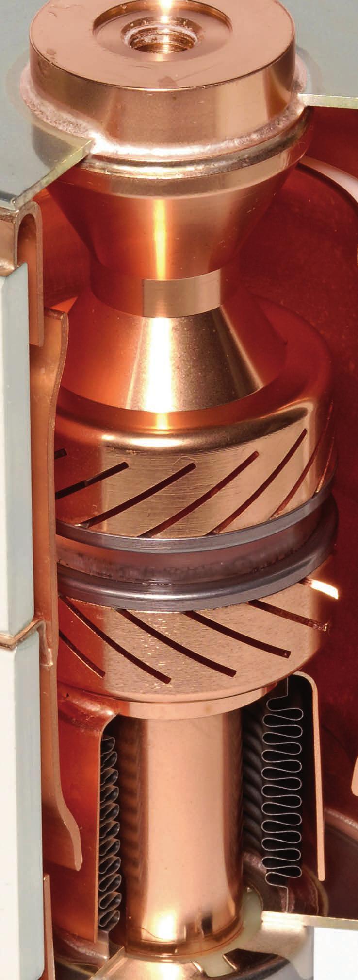
57
TeSys contactors. Model d. Type of contactor LC1- LC1- LC1- LC1- LC1-D115 & D09 D18 D25 D38 D40 D50 D95 LC1-D150 DT20 & DT25 DT32 & DT40
 Characteristics Type of contactor LC- LC- LC- LC- LC-D & D09 D8 D2 D38 D40 D0 D9 LC-D0 DT20 & DT2 DT32 & DT40 Environment Rated insulation voltage (Ui) Conforming to IEC 947-4-, overvoltage category III,
Fixed-Mounted Circuit-Breaker Switchgear Type NXPLUS up to 40.5 kv, Gas-Insulated
 Fixed-Mounted Circuit-Breaker Switchgear Type NXPLUS up to 40.5 kv, Gas-Insulated Medium-Voltage Switchgear Totally Integrated Power NXPLUS Catalog HA 35.51 Edition 2015 siemens.com/medium-voltage-switchgear
I r A Protection against direct contact Finger and back of hand proof to VDE 0106 Part 100
 DATASHEET - NZMH2-A100 Circuit-breaker, 3p, 100A Part no. NZMH2-A100 Catalog No. 259099 Similar to illustration Delivery program Product range Circuit-breaker Protective function System and cable protection
I r A Protection against direct contact Finger and back of hand proof to VDE 0106 Part 100
 DATASHEET - NZMC1-A160 Circuit-breaker, 3p, 160A Part no. NZMC1-A160 Catalog No. 283296 Similar to illustration Delivery program Product range Circuit-breaker Protective function System and cable protection
Series CT7N Bimetallic Overload Relays
 Series CT7N imetallic Overload Relays Choose CT7N overloads in DC applications and when monitoring Variable Frequency Drives Sprecher + Schuh has always paid particular attention to the subject of motor
Bulletin 190 IEC Modular Starter System
 Bulletin 90 Table of Contents Selection Guide Description Page Bulletin 90....................................... Accessories....................................... 7 Specifications.....................................
Protective function Systems, cable, selectivity and generator protection. i 2 t constant function: switchable. I r A
 DATASHEET - NZMN3-VE630 Circuit-breaker, 3p, 630A Part no. NZMN3-VE630 Catalog No. 259133 EL-Nummer (Norway) 0004358791 Similar to illustration Delivery program Product range Circuit-breaker Protective
Description Set value in neutral conductor is synchronous with set value Ir of main pole. R.m.s. value measurement and thermal memory CSA 100
 DATASHEET - NZMN3-4-AE400 Circuit-breaker, 4p, 400A Part no. NZMN3-4-AE400 Catalog No. 265891 Similar to illustration EL-Nummer (Norway) 0004358857 Delivery program Product range Circuit-breaker Protective
Modular pulse operated latching relay 16 A
 87045 LIMOGES Cedex Telephone number: +33 (0)5 55 06 87 87 Fax: +33 (0)5 55 06 88 88 Modular pulse operated latc / 05 / 07 / 08 / 10 / 11 / 12 / 14 / 16 / 20 and 927 00 / 49 CONTENTS PAGES 1. Description,
High performance circuit breakers
 Series High performance Description The high performance MCB offers a compact solution to circuit protection. The devices are DIN rail mounted. The is available with application-specific trip characteristics
Magnetic and Hydraulic-Magnetic Circuit Breaker
 Magnetic and Hydraulic-Magnetic Circuit Breaker 850-... Description Single, two, three and four pole magnetic and hydraulic-magnetic circuit breakers with trip-free-mechanism and toggle or rocker actuation.
02/11/2015
 DIN Rail Mount 17.5 mm MUS/MUSF 80 AC/DC Part number 84872141 Control relays monitoring their own power supply - MUS : Over/undervoltage control Selectable latching (memory) function - MUSF : Over/undervoltage
Description Set value in neutral conductor is synchronous with set value Ir of main pole. CSA 100. conductor. I r A 50-63
 Circuit-breaker,4p,63A Partno. NZMH1-4-A63 Articleno. 284426 Similar to illustration Deliveryprogram Product range Circuit-breaker Protective function System and cable protection Standard/Approval IEC
HD4/R. MV SF6 circuit-breakers for secondary distribution
 HD4/R MV SF6 circuit-breakers for secondary distribution DESCRIPTION CIRCUIT-BREAKER SELECTION AND ORDERING SPECIFIC PRODUCT CHARACTERISTICS OVERALL DIMENSIONS ELECTRIC CIRCUIT DIAGRAM 3 9 25 45 49 1
Data sheet. CI-TI TM Contactors and Motor Starters Contactors CI EI 520B1286
 CI-TI TM Contactors and Motor Starters June 2002 DKACT.PD.C00.I2.02 520B1286 Introduction are intended for a.c. coil voltages and cover the power range 45-238 kw. The largest types, CI 170 EI-420 EI have
LC3D115M7 TeSys D - star delta starter - 3 x 3P (3 NO) A V AC coil
 A V AC coil") Characteristics TeSys D - star delta starter - 3 x 3P (3 NO) - 115 A - 220 V AC coil Main Range Product name Product or component type Device short name Contactor application Utilisation category Device
Characteristics TeSys D - star delta starter - 3 x 3P (3 NO) - 115 A - 220 V AC coil Main Range Product name Product or component type Device short name Contactor application Utilisation category Device
Protective function Systems, cable, selectivity and generator protection. i 2 t constant function: switchable. I r A
 Deliveryprogramme Circuitbreak.3pselect.protection Partno. Articleno. 265777 NZMH4-VE1600 Product range Circuit-breaker Protective function Systems, cable, selectivity and generator protection Standard/Approval
LC2D09E7 REVERSING CONTACTOR 575VAC 9A IEC
 Product datasheet Characteristics LC2D09E7 REVERSING CONTACTOR 575VAC 9A IEC Price* : 86.25 GBP Main Range Product name Product or component type Device short name Contactor application Utilisation category
Type: DILM25 10(24V50HZ) Article No.:
 Article No.:") Type: DILM25 10(24V50HZ) Article No.: 277119 Ordering information Rated operational current AC 3 400 V I e A 25 Max. rating for three phase motors, 50 60 Hz AC 3 230 V Max. rating for three phase motors,
Type: DILM25 10(24V50HZ) Article No.: 277119 Ordering information Rated operational current AC 3 400 V I e A 25 Max. rating for three phase motors, 50 60 Hz AC 3 230 V Max. rating for three phase motors,
Systems Pow-R Breakers Renewal Parts and Accessories
 Systems Pow-R Breakers Renewal Parts and Accessories Renewal Parts RP01301013E Effective February 2006 Supersedes RPD29-890A pages 1 16 dated, March 2000 Cutler-Hammer SPB 100, 65 and 50 Series Contents
Generator protection relay
 Page 1 Issued: April 1999 Status: New Data subject to change without notice Features Off-the-shelf generator protection relay for small and medium sized power generators Three-phase time overcurrent and
Soft starter, 66 A, V AC, Us= 24 V DC, with control unit, Frame size N. Function Soft starter for three-phase loads, with control unit
 DATASHEET - S811+N66N3S Delivery program Soft starter, 66 A, 200-600 V AC, Us= 24 V DC, with control unit, Frame size N Part no. S811+N66N3S Catalog No. 168978 Eaton Catalog No. S811PLUSN66N3S EL-Nummer
Climatic proofing Damp heat, constant, to IEC Damp heat, cyclic, to IEC
 Deliveryprogramme Contactorrelay,3N/O+1N/C,AC Partno. DILER-31(230V50HZ,240V60HZ) Articleno. 051768 CatalogNo. XTRM10A31F Product range DILER Mini-contactors Application Contactor relays Description with
Series CDP2 Definite Purpose Contactors
 Series CDP2 Definite Purpose Contactors High performance economical contactors for commercial applications up to 90 Sprecher + Schuh s Definite Purpose contactors are ideal for commercial applications
AS09..S 3-pole Contactors - Spring Terminals
 4 kw 5 hp AS09..S 3-pole Contactors - Spring AC Operated Description - 3-pole contactors with spring terminals, - N.C. or N.O. built-in auxiliary contact, - Rail-mounted, no tools required, - Additional
LC1D12B7 TeSys D contactor - 3P(3 NO) - AC-3 - <= 440 V 12 A - 24 V AC coil
 - AC-3 - <= 440 V 12 A - 24 V AC coil") Characteristics TeSys D contactor - 3P(3 NO) - AC-3 -
Characteristics TeSys D contactor - 3P(3 NO) - AC-3 -
I r A Protection against direct contact Finger and back-of-hand proof to VDE 0106 part 100
 Circuit-breaker,3p,400A Partno. LZMC3-A400-I Articleno. 111955 Similar to illustration Deliveryprogramme Product range Circuit-breaker Protective function System and cable protection Standard/Approval
LC1D09FE7 TeSys D contactor - 3P(3 NO) - AC-3 - <= 440 V 9 A V AC coil
 - AC-3 - <= 440 V 9 A V AC coil") Product datasheet Characteristics LC1D09FE7 TeSys D contactor - 3P(3 NO) - AC-3 -
Product datasheet Characteristics LC1D09FE7 TeSys D contactor - 3P(3 NO) - AC-3 -
DMX and 4000 air circuit breakers from 800 to 4000 A
 DMX 3 20 and 00 air circuit breakers from 800 to 00 NEW 286 56 + 288 02 (p. 4) 286 4 + 288 02 (p. 4) 28 56 + 288 02 (p. 4) Dimensions (p. to 53) Electrical characteristics (p. 54 to 5) ir circuit breakers
LC1D65AF7 TeSys D contactor - 3P(3 NO) - AC-3 - <= 440 V 65 A V AC 50/60 Hz coil
 - AC-3 - <= 440 V 65 A V AC 50/60 Hz coil") Characteristics TeSys D contactor - 3P(3 NO) - AC-3 -
Characteristics TeSys D contactor - 3P(3 NO) - AC-3 -
I r A Protection against direct contact Finger and back of hand proof to VDE 0106 Part 100
 Circuit-breaker,3p,160A Partno. NZMN2-M160 CatalogNo. 265724 Similar to illustration Deliveryprogram Product range Circuit-breaker Protective function Motor protection Standard/Approval IEC Installation
Features XT SC 012 B B A
 Motor Control and Protection. XT IEC Manual and Combination Motor Controllers Selection XT IEC Manual and Combination Motor Controllers Manual and Combination Motor Controllers Design XT = XT IEC power
I r A I i = I n x. Protection against direct contact Finger and back of hand proof to VDE 0106 Part 100
 Deliveryprogramme Circuitbr.,3pmotorprotection Partno. Articleno. 265784 NZMN4-ME875 Product range Circuit-breaker Protective function Motor protection Standard/Approval IEC Installation type Fixed Release
Power Circuit of a UL508A Panel. Typical UL489 Application
 Typical UL489 Application Power Circuit of a UL508A Panel Disclaimer: This is an application example. Installation should be done by a qualified electrician under the guidance of UL specifications.. Altech
Linear flow controls VFC Linear flow controls with actuator IFC
 Linear flow controls VFC Linear flow controls with actuator Product brochure GB 3 Edition 01.16 Linear relationship between adjustment angle and flow rate Large control ratio of 25:1 Actuators IC 20 or
with handle LIMOGES Cedex 1. DESCRIPTION - USE 3. DIMENSIONS Symbol: Technology: Use:. For controlling a load remotely via a switch 2.
 87045 LIMOGES Cedex Téléphone : 05 55 06 87 87 Télécopie : 05 55 06 88 88 25A power contactors silent CONTENTS PAGES 1. Description, use... 1 2. Range... 1 3. Dimensions... 1 4. Positioning - Connection...
Ordering details. Approval. Classification
 Datasheet - SRB 301MC-24V Guard door monitors and Safety control modules for Emergency Stop applications / General Purpose safety controllers (Series PROTECT SRB) / SRB 301MC Fit for signal evaluation
Circuit-Breakers for Motor Protection Series 8523/8
 > Accessories Auxiliary contacts 1 NC + 1 NO or 2 NC + 2 NO Undervoltage trip Shunt release > Switch operation with knop > Secure switching > Clear switch setting indicator > Different current setting
LC1D80F7 TeSys D contactor - 3P(3 NO) - AC-3 - <= 440 V 80 A V AC 50/60 Hz coil
 - AC-3 - <= 440 V 80 A V AC 50/60 Hz coil") Product datasheet Characteristics LC1D80F7 TeSys D contactor - 3P(3 NO) - AC-3 -
Product datasheet Characteristics LC1D80F7 TeSys D contactor - 3P(3 NO) - AC-3 -
PRINCIPLES AND APPLICATIONS
 GENERATION & NETWORK Digital Automation Measuring and Control Devices AMS7000 PROCOM The optimum operation of an electrical network depends particularly on the reliability and the availability of the protection,
Linear flow control with actuator IFC
 Linear flow control with actuator Product brochure GB 3 Edition 01.14 Linear relationship between adjustment angle and flow rate Large control ratio of 25:1 EC type-tested and certified Actuators IC 20
MILLITARY SPECIFICATION SHEET
 INCH-POUND MILLITARY SPECIFICATION SHEET 10 November 2000 SUPERSEDING MIL-R-6106/14B 10 March 1989 RELAY, ELECTRIC, PERMANENT DRIVE, 50 AMP, SPDT (DB) DOUBLE MAKE DOUBLE BREAK AUXILIARY CONTACTS (5 AMP),
LC1D12P7 TeSys D contactor - 3P(3 NO) - AC-3 - <= 440 V 12 A V AC coil
 - AC-3 - <= 440 V 12 A V AC coil") Characteristics TeSys D contactor - 3P(3 NO) - AC-3 -
Characteristics TeSys D contactor - 3P(3 NO) - AC-3 -
Type: DILM12 10(24VDC) Article No.:
 Article No.:") Type: DILM12 10(24VDC) Article No.: 276845 Ordering information Rated operational current AC 3 400 V I e A 12 Max. rating for three phase motors, 50 60 Hz AC 3 230 V Max. rating for three phase motors,
Type: DILM12 10(24VDC) Article No.: 276845 Ordering information Rated operational current AC 3 400 V I e A 12 Max. rating for three phase motors, 50 60 Hz AC 3 230 V Max. rating for three phase motors,
Features XT SC 012 B B A
 Motor Control and Protection. XT IEC Manual and Combination Motor Controllers Selection XT IEC Manual and Combination Motor Controllers Manual and Combination Motor Controllers Design XT = XT IEC power
LC1D50AF7 TeSys D contactor - 3P(3 NO) - AC-3 - <= 440 V 50 A V AC 50/60 Hz coil
 - AC-3 - <= 440 V 50 A V AC 50/60 Hz coil") Product data sheet Characteristics LC1D50AF7 TeSys D contactor - 3P(3 NO) - AC-3 -
Product data sheet Characteristics LC1D50AF7 TeSys D contactor - 3P(3 NO) - AC-3 -
LC1D09F7 TeSys D contactor - 3P(3 NO) - AC-3 - <= 440 V 9 A V AC coil
 - AC-3 - <= 440 V 9 A V AC coil") Product data sheet Characteristics LC1D09F7 TeSys D contactor - 3P(3 NO) - AC-3 -
Product data sheet Characteristics LC1D09F7 TeSys D contactor - 3P(3 NO) - AC-3 -
Magnecraft Power Relays
 Description DPST-NO, 30 A; DPDT, 30 A (NO) / 3 A (NC) Description The series power relays offer a small package size and features Class F insulation for a maximum coil temperature of 55 C (3 F). These
Fixed-Mounted Circuit-Breaker Switchgear Type NXPLUS C up to 24 kv, Gas-Insulated
 Catalog HA 35.41 2016 Fixed-Mounted Circuit-Breaker Switchgear Type NXPLUS C up to 24 kv, Gas-Insulated Medium-Voltage Switchgear siemens.com/medium-voltage-switchgear R-HA35-126.tif Application Public
LC3D180AV7 TeSys D - star delta starter - 3 x 3P (3 NO) - 18 A V AC coil
 - 18 A V AC coil") Characteristics TeSys D - star delta starter - 3 x 3P (3 NO) - 18 A - 400 V AC coil Main Range Product name Product or component type Device short name Contactor application Utilisation category Device
Characteristics TeSys D - star delta starter - 3 x 3P (3 NO) - 18 A - 400 V AC coil Main Range Product name Product or component type Device short name Contactor application Utilisation category Device
Datasheet - SRB301LC 24VAC/DC
 25.02.2016-18:05:23h Datasheet - SRB301LC 24VAC/DC Guard door monitors and Safety control modules for Emergency Stop applications / General Purpose safety controllers (Series PROTECT SRB) / SRB301LC Preferred
 SINCE 1989 Quality Products, Prompt Services, Trustful Relationships www.kmindustrialcorp.com KM Industrial Corporation has established itself as a trusted supplier of Electrical, Machinery and Industry
LC1D32P7 TeSys D contactor - 3P(3 NO) - AC-3 - <= 440 V 32 A V AC 50/60 Hz coil
 - AC-3 - <= 440 V 32 A V AC 50/60 Hz coil") Characteristics TeSys D contactor - 3P(3 NO) - AC-3 -
Characteristics TeSys D contactor - 3P(3 NO) - AC-3 -
HYL-080D1750G358. Constant current LED driver DALI Dimmable. LED Driver. Product description. Benefits. Interfaces.
 Linear / area dimming Constant current LED driver DALI Dimmable Product description Dimmable built-in constant current LED Driver Adjustable output current between 1,050 and 1,750mA via DIP switch Max.
SQM40/41 Actuators for air and gas dampers
 SQM40/41 Actuators for air and gas dampers Description SQM40/41 actuators are used for the positioning of flow control valves, butterfly valves, dampers or any application requiring rotary motion. The
llen-bradley 194R-HM4-NFPA3
 Technical Data Rotary Disconnect Switch Specifications Bulletin Number 194R Topic Page Product Line Overview 2 General Specifications Fuse Description 12 Approximate Dimensions 14 Additional Resources
Intelligent compressor solutions. EFC, EFCe Systems Electronic Frequency Control EFC. EFCe
 EFC, EFCe Systems Electronic Frequency Control Continuously variable speed control using frequency converter technology With the EFC and EFCe system Bock offers the most efficient means of adapting the
Catalogue Ignitors and power switches for HID
 Catalogue 2012 Ignitors and power switches for HID Overview Product overview Ignitor matrix Standards Page 6 Page 7 Page 8 Product information Ignitors and power switches for HID Page 9 Superimposed-pulse
LC1D50AFE7 TeSys D contactor - 3P(3 NO) - AC-3 - <= 440 V 50 A V AC 50/60 Hz coil
 - AC-3 - <= 440 V 50 A V AC 50/60 Hz coil") Product data sheet Characteristics LC1D50AFE7 TeSys D contactor - 3P(3 NO) - AC-3 -
Product data sheet Characteristics LC1D50AFE7 TeSys D contactor - 3P(3 NO) - AC-3 -
Protection against direct contact Finger and back of hand proof to VDE 0106 Part 100
 Circuit-breaker3psystems/cableprot. Partno. NZMB2-A250 Articleno. 259090 Deliveryprogramme Range Circuit-breaker Protective function System and cable protection Standard/Approval IEC Installation type
Magnecraft General Purpose Relays 750R Series DPDT and 3DPT, 10 A
 and 3DPT, 10 A UL Listed when used with proper Magnecraft s The 750R series octal base, plug-in relays offer clear or full-feature covers with multiple mounting options and accessories. 750R 750R Full-Feature
1.1. IEC Contactors and Starters. Contents Description Relays and Timers... Miniature Controls... Contactors and Starters. XT IEC Power Control
 IEC Contactors and Starters. XT Family of Contactors Contactors and Starters Product Description The Eaton XT contactors and starters includes nonreversing and reversing contactors, overload relays and
Analog Input Module HART Ex i / I.S. Inputs, 8 Channels Type 9461/
 > 8 channels for 2-wire HART transmitters > Intrinsically safe inputs Ex ia IIC > Galvanic separation between inputs and system > Open-circuit and short-circuit monitoring for each field circuit > Module
SITOP power supply. Technical data, April SITOP Power Supply. Answers for industry.
 SITOP power supply Technical data, April 2010 SITOP Power Supply Answers for industry. SITOP reliable power supply Efficient operation of a machine or plant requires a reliable, constant power supply.
LED Driver Linear / area fixed output
 Driver LC 10W 350mA fixc lp SNC2 ESSENCE series Product description Fixed output built-in LED Driver Constant current LED Driver Output current 350 ma Max. output power 10.2 W Up to 80 % efficiency For
A V 50Hz / V 60Hz
 A16-22-00 400-415V 50Hz / 415-440V 60Hz Products Low Voltage Products and Systems Control Products Contactors Block Contactors General Information Extended Product Type: A16-22-00 400-415V 50Hz / 415-440V
LED Driver Linear / area dimming industry. Driver LC 200W 1050mA UNV ADV IND ADVANCED series
 Driver LC 200W 1050mA UNV ADV IND ADVANCED series Product description Independent constant current LED Driver For dry, damp and wet locations Max. output power 200 W Up to 93.7 % efficiency For luminaires
and Refrigeration Institute). CAQ7 Capacitor Switching Contactors
. CAQ7 Capacitor Switching Contactors") SSN9000 Series C7 Special Use designed and labeled for specific industrial applications Special Use Capacitor switching contactors HVC rated contactors NEM size labeled contactors Lighting contactors Hydraulic
SSN9000 Series C7 Special Use designed and labeled for specific industrial applications Special Use Capacitor switching contactors HVC rated contactors NEM size labeled contactors Lighting contactors Hydraulic
Gamma instabus. Technical product information
 Gamma instabus Technical product information Universal dimmer N 554D31, 4 x 300 VA / 1x 1000 VA, AC 230 V Universal dimmer N 554D31 Control of dimmable lamps, including LED without minimum load Output
HYL-035D0850G103. Constant current LED driver DALI Dimmable. LED Driver. Product description. Benefits. Interfaces.
 Constant current LED driver DALI Dimmable Product description Dimmable Independent constant current Adjustable output current between 350 and 1,050mA via DIP switch Max. output power 35 W Up to 88 % efficiency
Datasheet - SRB-E-201ST
 27.04.2016-16:36:21h Datasheet - SRB-E-201ST Multi-function safety modules / SRB-E-201ST STOP 0 Function 1 oder 2-channel control Start button / Auto-start Monitoring two-hand control panels to EN 574
Electrical connection
 Splice sensor Dimensioned drawing en 04-2014/06 50116166-01 4mm 12-30 V DC We reserve the right to make changes DS_IGSU14CSD_en_50116166_01.fm Reliable detection of splice on paper web or plastic web With
LC1D25G7 TeSys D contactor - 3P(3 NO) - AC-3 - <= 440 V 25 A V AC coil
 - AC-3 - <= 440 V 25 A V AC coil") Product data sheet Characteristics LC1D25G7 TeSys D contactor - 3P(3 NO) - AC-3 -
Product data sheet Characteristics LC1D25G7 TeSys D contactor - 3P(3 NO) - AC-3 -
LC1D09B7 TeSys D contactor - 3P(3 NO) - AC-3 - <= 440 V 9 A - 24 V AC coil
 - AC-3 - <= 440 V 9 A - 24 V AC coil") Product data sheet Characteristics LC1D09B7 TeSys D contactor - 3P(3 NO) - AC-3 -
Product data sheet Characteristics LC1D09B7 TeSys D contactor - 3P(3 NO) - AC-3 -
3.5. Control Relays and Timers. Contents. 9575H Series 3000 Type AA, AC and DC. General Purpose Relays Type AA
 .5 9575H Series 000 Relay Contents 9575H Series 000 Type AA, AC and DC Product Selection....................... Accessories............................ Technical Data and Specifications........... Dimensions............................
LC1D150G7 TeSys D contactor - 3P(3 NO) - AC-3 - <= 440 V 150 A V AC coil
 - AC-3 - <= 440 V 150 A V AC coil") Product data sheet Characteristics LC1D150G7 TeSys D contactor - 3P(3 NO) - AC-3 -
Product data sheet Characteristics LC1D150G7 TeSys D contactor - 3P(3 NO) - AC-3 -
Series CDP2 Definite Purpose Contactors
 Series 2 Definite Purpose High performance economical contactors for commercial applications up to 90 Sprecher + Schuh s Definite Purpose contactors are ideal for commercial applications including air
LC1D150B7 TeSys D contactor - 3P(3 NO) - AC-3 - <= 440 V 150 A - 24 V AC 50/60 Hz coil
 - AC-3 - <= 440 V 150 A - 24 V AC 50/60 Hz coil") Product data sheet Characteristics LC1D150B7 TeSys D contactor - 3P(3 NO) - AC-3 -
Product data sheet Characteristics LC1D150B7 TeSys D contactor - 3P(3 NO) - AC-3 -
LED Driver Compact fixed output
 Driver LC 45W 1050mA fixc C SNC ESSENCE series Product description Fixed output built-in LED Driver Constant current LED Driver Output current 1,050 ma output power 45 W Nominal life-time up to 50,000
Catalogue numbers. PowerPact Multistandard. H-Frame, J-Frame unit-mount circuit breaker F-2. H-Frame, J-Frame circuit breaker accessories F-3
 PowerPact Multistandard Catalogue numbers Functions and characteristics A-1 Installation recommendations B-1 Dimensions C-1 Wiring diagrams D-1 Additionals characteristics E-1 H-Frame, J-Frame unit-mount
LC3D80B7 TeSys D - star delta starter - 3 x 3P (3 NO) - 80 A - 24 V AC coil
 - 80 A - 24 V AC coil") Characteristics TeSys D - star delta starter - 3 x 3P (3 NO) - 80 A - 24 V AC coil Price* : 4058.00 USD has not been replaced. Please contact your customer care center for more information. Main Range
Characteristics TeSys D - star delta starter - 3 x 3P (3 NO) - 80 A - 24 V AC coil Price* : 4058.00 USD has not been replaced. Please contact your customer care center for more information. Main Range
Minicontactorrelay,2NO/2NC,DCoperated
 Minicontactorrelay,2NO/2NC,DCoperated Partno. DILER-22-G(24VDC) Articleno. 010042 CatalogNo. XTRM10A22TD Deliveryprogramme Product range DILER Mini-contactors Application Contactor relays Connection technique
Selection guide siemens.com/sirius-modular-system
 SIRIUS modular system Selection guide siemens.com/sirius-modular-system Everything for the control cabinet: SIRIUS modular system Efficiently combined Advantages at a glance: Load feeders: easy to implement
LXM23DU10M3X motion servo drive - Lexium 23 - single phase V - 1 kw - I/O
 Characteristics motion servo drive - Lexium 23 - single phase 200...255 V - 1 kw - I/O Main Range of product Product or component type Device short name Complementary Format of the drive Network number
LED Driver Compact dimming
 Driver CA 15W 180-350mA flexc PH-C SR ADV ADVACED series Product description Dimmable constant current ED Driver (SEV) Independent ED Driver with cable clamps Selectable output current between 180, 250
and Refrigeration Institute). Hydraulic Elevator Wye-Delta Contactors
. Hydraulic Elevator Wye-Delta Contactors") C7 Series C7 Special Use designed and labeled for specific industrial applications The C7 line includes a number of contactors designed and labeled for specific industrial applications. In most cases,
C7 Series C7 Special Use designed and labeled for specific industrial applications The C7 line includes a number of contactors designed and labeled for specific industrial applications. In most cases,
LED Driver Compact fixed output
 Driver LC 40W 900mA fixc C SNC ESSENCE series Product description Fixed output built-in LED Driver Constant current LED Driver Output current 900 ma Max. output power 40 W Nominal life-time up to 50,000
Movable Contacts Heavy duty silver cadmium oxide composition to resist welding and contact erosion for greater reliability
 Compare These Features Built-in Shock bsorber Reduces contact bounce for longer life. Coil Dust Cover Keeps dust and dirt away from magnet and coil area. Coil Class B (1300 C Insulation System) with wide
Analog Input Module HART Ex n Inputs, 8 Channels Series 9461/15
 > 8 channels for 2-wire HART transmitters > Inputs for Ex nl, Ex na and Nonincendive > Galvanic separation between inputs and system > Open-circuit and short-circuit monitoring for each field circuit >
1.1. IEC Contactors and Starters. Contents Description Relays and Timers... Miniature Controls... Contactors and Starters. XT IEC Power Control
 XT Family of Contactors Contactors and Starters Product Description The Eaton XT contactors and starters includes nonreversing and reversing contactors, overload relays and a variety of related accessories.
PHASED OUT. LED control gear Compact fixed output. Driver LC 40W 900mA fixc C SNC China Domestic ESSENCE series
 Product description Fixed output built-in LED Driver Constant current LED Driver Output current 900 ma Max. output power 40 W Nominal life-time up to 30,000 h For luminaires of protection class I and protection
CAMTO LTD. Arc detecting system DC/AC
 CAMTO LTD Arc detecting system DC/AC Arc detecting system DC/AC The system is based on experience with arc protection since 1962. The system units are built into boxes that all fit on a 35 mm DIN-rail.
LED Driver Linear / area dimming
 Driver LCA 75W 350 1050mA one4all lp PRE PREMIUM series Product description Dimmable built-in constant current LED Driver Adjustable output current between 350 and 1,050 ma via ready2mains Programmer,
LC1D09M7 TeSys D contactor - 3P(3 NO) - AC-3 - <= 440 V 9 A V AC coil
 - AC-3 - <= 440 V 9 A V AC coil") Bảng thông số sản phẩm Đặc diểm LC1D09M7 TeSys D contactor - 3P(3 NO) - AC-3 -
Bảng thông số sản phẩm Đặc diểm LC1D09M7 TeSys D contactor - 3P(3 NO) - AC-3 -
MIKRO POWER FACTOR CORRECTION COMPONENTS
 MIKRO POWER FACTOR CORRECTION COMPONENTS MIKRO POWER FACTOR REGULATOR Steps 6, 8, 12, 14 Voltage 1 4V AC Frequency 0 and 60 Hz Detection method Displacement Power Factor Input current A Modes Automatic,
Assembly. Front view. LEDs. Parametrization interface. Power Bus
 otation Speed Monitor Features Assembly 1-channel signal conditioner 2 V DC supply Input for 2- or -wire sensors Input frequency 10 mhz... 50 khz elay contact output Start-up override and restart inhibit
ORDERING Page 6 STANDARDS, DIMENSIONS and ACCESSORIES Request bulletin SDA
 BE1-59NC CAPACITOR NEUTRAL OVERVOLTAGE RELAY The BE1-59NC Capacitor Neutral Overvoltage Relay provides sensitive protection for capacitor banks. ADVANTAGES Helps avoid cascading capacitor failures. Sensing
EMC Solutions Noise filtering
 Power & Signal Quality TRABTECH EMC Solutions Noise filtering Interference-free power supply and signal transmission A permanent supply and safe data link are essential for the operational reliability
Medium and High Voltage Circuit Breakers Characteristic Time Quantities of the Circuit Breaker with Applications
 Workshop 6: Maintenance and monitoring Medium and High Voltage Circuit Breakers Characteristic Time Quantities of the Circuit Breaker with Applications Alexander Herrera OMICRON electronics GmbH 3 December
ALLEN BRADLEY TIMING RELAY
 ALLEN BRADLEY TIMING RELAY Configuration Details Product: 700-HS12BA1 Description: 700-HS General Purpose Square Base Timing Relay, On Delay Timer, 1.0 to 180 seconds, DPDT, 120V AC 50/60Hz CONTROL RELAY