TEST REPORT. ASTM E a. Fire Tests of Building Construction and Materials 1-HR FIRE RESISTANCE TEST OF A NON-LOADBEARING STRAW BALE WALL
|
|
|
- Bethanie Bates
- 6 years ago
- Views:
Transcription
 210-635-8100 (fax) 210-635-8101 www.interteketlsemko.")
1 TEST REPORT ASTM E a Fire Tests of Building Construction and Materials 1-HR FIRE RESISTANCE TEST OF A NON-LOADBEARING STRAW BALE WALL Project No B July 31, 2006 Revised: July 9, 2007 Intertek Testing Services NA, Inc Shady Falls Road Elmendorf, TX (voice) (fax) Prepared for: Ecological Building Network 11 Mark Drive San Rafael, CA 94903
2
3 TABLE OF CONTENTS ITEM PAGE Introduction 1 Test Procedure 4 Conditions of Acceptance 8 Test Specimen Construction 9 Test Results and Observations 11 Conclusions 13 Appendices Appendix A: Construction Drawings 14 Appendix B: Thermocouple Layout 16 Appendix C: Temperature Data 18 Appendix D: Photographs 28 Appendix E: ASTM C 42 Compression Results 39 Last Page of Report 40 Intertek Testing Services NA, Inc Shady Falls Road, Elmendorf, Texas / FAX: /
4 Project No B Revised: July 9, 2007 July 31, 2006 EBNet Page 1 INTRODUCTION1 "The performance of walls, columns, floors, and other building members under fire exposure conditions is an item of major importance in securing constructions that are safe, and that are not a menace to neighboring structures nor to the public. Recognition of this is registered in the codes of many authorities, municipal and other. It is important to secure balance of the many units in a single building, and of buildings of like character and use in a community; and also to promote uniformity in requirements of various authorities throughout the country. To do this it is necessary that the fire-resistive properties of materials and assemblies be measured and specified according to a common standard expressed in terms that are applicable alike to a wide variety of materials, situations, and conditions of exposure. Such a standard is found in the methods that follow. They prescribe a standard exposing fire of controlled extent and severity. Performance is defined as the period of resistance to standard exposure elapsing before the first critical point in behavior is observed. Results are reported in units in which field exposures can be judged and expressed. The methods may be cited as the "Standard Fire Tests," and the performance or exposure shall be expressed as "2-h," "6-h," "1/2-h," etc. When a factor of safety exceeding that inherent in the test conditions is desired, a proportional increase should be made in the specified time-classification period. The ASTM E 119 test procedure is identical or very similar to the following standard test methods: UL 263 UBC 7-1 NFPA 251 ANSI A2.1 ULC S101 The analogous test standard in the International Organization of Standardization (ISO), ISO 834 Fire-resistance Tests Elements of Building Construction, is very similar to the above U.S. test methods. Its exposure curve, as well as the method used to measure temperatures within the furnace result in a slightly less severe temperature exposure 1 ASTM E a Standard Test Methods for Fire Tests of Building Construction and Materials ASTM International, Volume Building Seals and Sealants, etc.
5 Project No B Revised: July 9, 2007 July 31, 2006 EBNet Page 2 than the E 119 test for the first two hours. The ISO 834 test requires a slightly greater positive pressure within the furnace. For those reasons, the E119 test can be considered to be slightly more severe for tests of 2 h duration or less, only if the test article is not likely to be affected by a higher furnace pressure. (BS 476 Pt 20 Fire tests on building materials and structures is virtually identical to the ISO 834 test method, as is the new CEN standard, EN ) 1. Scope The test methods described in this fire-test-response standard are applicable to assemblies of masonry units and to composite assemblies of structural materials for buildings, including bearing and other walls and partitions, columns, girders, beams, slabs, and composite slab and beam assemblies for floors and roofs. They are also applicable to other assemblies and structural units that constitute permanent integral parts of a finished building. 1.2 It is the intent that classifications shall register comparative performance to specific fire-test conditions during the period of exposure and shall not be construed as having determined suitability for use under other conditions or after fire exposure. 1.3 This standard is used to measure and describe the response of materials, products, or assemblies to heat and flame under controlled conditions, but does not by itself incorporate all factors required for fire hazard or fire risk assessment of the materials, products or assemblies under actual fire conditions. 1.4 These test methods prescribe a standard fire exposure for comparing the test results of building construction assemblies. The results of these tests are one factor in assessing predicted fire performance of building construction assemblies. Application of these test results to predict the performance of actual building construction requires the evaluation of test conditions. 1.5 The values stated in inch-pound units are to be regarded as the standard. The values given in parentheses are for information only. 1.6 This standard does not purport to address all of the safety concerns, if any, associated with its use. It is the responsibility of the user of this standard to establish appropriate safety and health practices and determine the applicability of regulatory limitations prior to use. 1.7 The text of this standard references notes and footnotes which provide explanatory material. These notes and footnotes (excluding those in tables and figures) shall not be considered as requirements of the standard.
6 Project No B Revised: July 9, 2007 July 31, 2006 EBNet Page 3 4. Significance and Use 4.1 This test method is intended to evaluate the duration for which the types of assemblies noted in 1.1 will contain a fire, retain their structural integrity or exhibit both properties dependent upon the type of assembly involved during a predetermined test exposure. 4.2 The test exposes a specimen to a standard fire controlled to achieve specified temperatures throughout a specified time period. When required, the fire exposure is followed by the application of a specified standard fire hose stream. The test provides a relative measure of the fire-test-response of comparable assemblies under these fire exposure conditions. The exposure is not representative of all fire conditions because conditions vary with changes in the amount, nature and distribution of fire loading, ventilation, compartment size and configuration, and heat sink characteristics of the compartment. Variation from the test conditions or specimen construction, such as size, materials, method of assembly, also affects the fire-test-response. For these reasons, evaluation of the variation is required for application to construction in the field. 4.3 The test standard provides for the following: For walls, partitions and floor or roof assemblies: Measurement of the transmission of heat Measurement of the transmission of hot gases through the assembly, sufficient to ignite cotton waste For load bearing elements, measurement of the load carrying ability of the test specimen during the test exposure For individual load bearing assemblies such as beams and columns: Measurement of the load carrying ability under the test exposure with some consideration for the end support conditions (that is, restrained or not restrained). 4.4 The test standard does not provide the following: Full information as to performance of assemblies constructed with components or lengths other than those tested Evaluation of the degree by which the assembly contributes to the fire hazard by generation of smoke, toxic gases, or other products of combustion Measurement of the degree of control or limitation of the passage of smoke or products of combustion through the assembly Simulation of the fire behavior of joints between building elements such as floorwall or wall-wall, etc., connections Measurement of flame spread over surface of tested element The effect of fire endurance of conventional openings in the assembly, that is electrical receptacle outlets, plumbing pipe, etc., unless specifically provided for in the construction tested."
7 Project No B Revised: July 9, 2007 July 31, 2006 EBNet Page 4 TEST PROCEDURE Test Furnace The test furnace is designed to allow the specimen to be uniformly exposed to the specified time-temperature conditions. It is fitted with 6 propane/air burners positioned on the left and right side walls, designed to allow an even heat flux distribution across the face of a test specimen while allowing no direct flame impingement. The maximum energy input into the furnace is 15 MBtu/hr. The furnace operator has controls which allow the following items to be varied during the test: the overall energy input into the furnace; the air/gas ratio to the burners; and, the input of additional air beyond that passing through the burners. The furnace opening is 14 ft wide, 12 ft tall and 4 ft deep. It may be fitted with a collar that reduces the front opening to 10 ft x 10 ft, if desired. Furnace pressures may be maintained at any value from +0.15" W.C. to -0.15" W.C. Any full-size vertical fire test furnace will have a pressure difference between the bottom and top of approximately 0.01 in. W.C. per vertical foot after operating temperatures are reached. For this reason, the furnace is operated by controlling the pressure within the furnace (with respect to the laboratory ambient pressure) by regulating the pressure at a specific horizontal plane in the furnace. The furnace pressure will often be adjusted so that the "neutral pressure plane" (that where the pressure difference between the furnace interior and the laboratory ambient is zero) is at a desired location: for instance; at the top, at a point 1 /3 of the way down from the top, or at the bottom of the specimen. The temperature within the furnace is determined to be the mathematical average of thermocouples located symmetrically within the furnace and positioned six inches away from the vertical face of the test specimen. The materials used in the construction of these thermocouples are those suggested in the test standard. During the performance of a fire exposure test, the furnace temperatures are recorded every 15 seconds and displayed for the furnace operator to allow control along the specified temperature curve. For report presentation purposes, the data is saved once per minute.

8 Project No B Revised: July 9, 2007 July 31, 2006 EBNet Page 5 This photograph of the vertical furnace shows it with a concrete adapter in place which reduces its opening to 120" x 120". Without the adapter the furnace will accept test specimens 144" tall x 168" wide. The furnace is 48" deep, with burners on the sides, so that no flame impingement on the specimen occurs. The furnace interior temperature during a test is controlled such that the area under the time temperature curve is within 10% of the corresponding area under the standard time temperature curve for 1 hour or less tests, 7.5% for those less than 2 hours and 5% for those tests of 2 hours or more duration.
9 Project No B Revised: July 9, 2007 July 31, 2006 EBNet Page 6 The fire exposure is controlled to conform with the standard time-temperature curve shown in Figure 1, as determined by the table below: 2250 ASTM E119 Time-Temperature Curve Time (min) Temperature ( F) Temperature ( F) Time (min) Figure 1 Fire Endurance Test The fire exposure is continued on the specimen with its applied load if applicable, until failure occurs, or until the specimen has withstood the test conditions for the desired fire endurance rating. Hose Stream Test "11.1 Where required by the conditions of acceptance, the hose stream test shall be conducted to subject the specimen described in 11.2 or 11.3 to the impact, erosion, and cooling effects of a hose stream Exemption The hose stream test shall not be required in the case of constructions having a resistance period, indicated in the fire endurance test, of less than 1 h.
10 Project No B Revised: July 9, 2007 July 31, 2006 EBNet Page The hose stream test shall be conducted on a duplicate test specimen The duplicate specimen shall be exposed to the effects of the hose stream immediately after being subjected to a fire endurance test for a time period of one-half the fire endurance classification period determined from the fire endurance test on the initial specimen The length of time that the duplicate specimen is subjected to the fire endurance test shall not exceed 1 h Optional Program As an alternative procedure, conduct the hose stream test on the initially tested specimen immediately following its fire endurance test In conducting the hose stream test, direct the hose stream first at the middle and then at all parts of the exposed face of the specimen. Any changes in direction shall be made slowly Stream Equipment and Details - The stream shall be delivered through a 2 1 /2-in. (64-mm) hose discharging through a National Standard Playpipe of corresponding size equipped with a 1 1 /8-in. (28.5-mm) discharge tip of the standard-taper smooth-bore pattern without shoulder at the orifice. The water pressure and duration of the application shall be as prescribed [in the table below]: Conditions For Hose Stream Test Water Pres- Duration of Application, Resistance sure at Base of min/100 ft 2 (9 m 2 ) Period Nozzle,psi (kpa) exposed area 8 h and over 45 (310) 6 4 h and over if less than 8 h 45 (310) 5 2 h and over if less than 4 h 30 (207) 2 1 /2 1-1/2 h and over if less than 2 h 30 (207) 1 1 /2 1 h and over if less than 1-1/2 h 30 (207) 1 Less than 1 h, if desired 30 (207) Nozzle Distance - The distance between the tip of the nozzle and the center of the exposed surface shall be determined by the deviation from normal between the center of the nozzle axis and the center of the exposed surface of the specimen. The distance shall be 20 ft (6 m) when the axis through the center of the nozzle is normal to the center of the exposed surface. This distance shall be decreased by an amount equal to 1 ft (305 mm) for each 10 of deviation from the normal."
11 Project No B Revised: July 9, 2007 July 31, 2006 EBNet Page 8 Correction Factor When the indicated resistance period is 1 /2 h or over, determined by the average or maximum temperature rise on the unexposed surface or within the test sample, or by failure under load, a correction shall be applied for variation of the furnace exposure from that prescribed, where it will affect the classification, by multiplying the indicated period by two thirds of the difference in area between the curve of average furnace temperature and the standard curve for the first three fourths of the period and dividing the product by the area between the standard curve and a base line of 68 F (20 C) for the same part of the indicated period, the latter area increased by 3240 F min to compensate for the thermal lag of the furnace thermocouples during the first part of the test. For a fire exposure in the test higher than standard, the indicated resistance period shall be increased by the amount of the correction. For a fire exposure in the test lower than standard, the indicated resistance period shall be similarly decreased for fire exposure below standard. The correction is accomplished by mathematically adding the correction factor, C, to the indicated resistance period. The correction can be expressed by the following equation: where: C = 2 I (A A s ) 3 (A s + L) C = correction in the same units as I, I = indicated fire-resistance period, A = area under the curve of indicated average furnace temperature for the first three fourths of the indicated period, A s = area under the standard furnace curve for the same part of the indicated period, and L = lag correction in the same units as A and A s (54 F h or 30 C h (3240 F min or 1800 C min)) CONDITIONS OF ACCEPTANCE 18. Conditions of Acceptance [Nonloadbearing Walls] 18.1 Regard the test as successful when the following conditions are met: The wall or partition has withstood the fire endurance test without passage of flame or gases hot enough to ignite cotton waste, for a period equal to that for which classification is desired.
12 Project No B Revised: July 9, 2007 July 31, 2006 EBNet Page The wall or partition shall has [sic] withstood the fire and hose stream test as specified in Sections 10 and 11, without passage of flame, of gases hot enough to ignite cotton waste, or of passage of water from the hose stream. The assembly shall be considered to have failed the hose stream test if an opening develops that permits a projection of water from the stream beyond the unexposed surface during the time of the hose stream test Transmission of heat through the wall or partition during the fire endurance test shall not have been such as to raise the [average] temperature on its unexposed surface more than 250 F (139 C) above its initial temperature. [The E119 standard further states:] 7.4 Where the conditions of acceptance place a limitation on the rise of temperature of the unexposed surface, the temperature end point of the fire endurance period shall be determined by the average of the measurements taken at individual points; except that if a temperature rise of 30% [325 F above initial temperature] in excess of the specified limit occurs at any one of these points, the remainder shall be ignored and the fire endurance period judged as ended. TEST SPECIMEN CONSTRUCTION The observations and test results in this report are relevant only to the sample tested. This report by itself does not imply that the material, product, or service is or has ever been under an Intertek certification program. The 12-ft tall x 14-ft wide wall assembly was constructed with rectangular wheat straw bales with the following nominal physical properties: 36-in long, 14-in tall (straw oriented horizontally), 18-in wide, 42.3 lbs each (7.5 pcf). Because the thickness of the bales was greater than the depth of the frame, the bales were installed flush to one side of the frame (the heated side). ½ plywood was placed under the bottom course and above the top course to assist in keeping the bales in plane. The bales were stacked in a running bond pattern 10 courses high, completely filling the test frame. The wheat straw bales had two polypropylene ties per bale (PolyLine 430, GREENLEE, 210 lb strength). The ties were placed in the wall in the on-bottom orientation, meaning that the poly ties were contained within the wall around the top and bottom of the bales, not directly exposed to the fire. The gaps at the intersections of the stacked bales were stuffed with a mud and straw mixture that was prepared using locally available dirt plus a small amount of chopped straw mixed with enough water to hold its shape, then pushed as far into the cracks as possible. The wall was constructed in a loadbearing test frame, which has a moveable bottom beam with hydraulic actuators below the
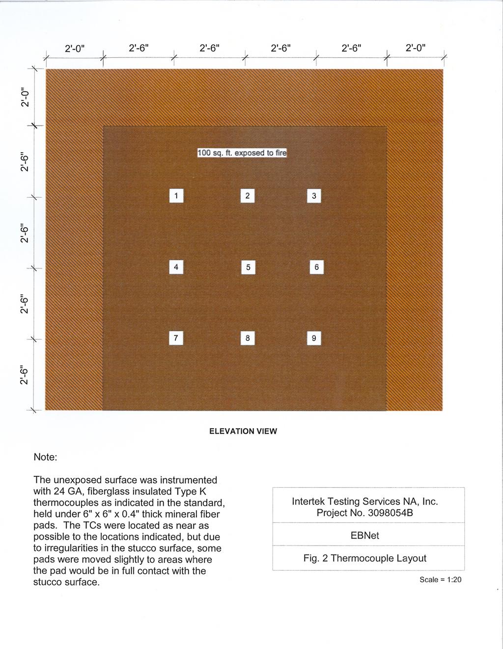
13 Project No B Revised: July 9, 2007 July 31, 2006 EBNet Page 10 beam. To impose a load on a wall, a hydraulic pump is used to apply pressure to the jacks which exert a force on the bottom beam and the wall is simply squeezed against the top of the test frame. This wall was intended to carry a superimposed load of 600 lbs / lineal foot during the test, so after the bales were stacked, this load was applied prior to the application of the earthen clay mixture. Though attempts were made to straighten the bales and keep them straight before and during application of the earthen plaster, the wall still had a significant bulge when the plaster was applied, thus becoming permanent. The bales had no interior or exterior vertical pinning. The earthen plaster was applied in two coats, each nominally ½ thick. The mix consisted of 3 parts clay, 2 parts chopped straw, 6 parts sand, and water to a sprayable consistency. The second coat was applied using hand trowels. The first coat was spray-applied on June 5, 2006 by representatives of EBNet. Beginning the next day, a large box fan was placed in front of the wall to assist in drying. On June 22, the second coat was applied with hand trowels. Each coat was nominally ½ thick. Two small wooden boxes were filled with earthen plaster taken from the mix used on both days of application. These samples were sent to a local lab and compression tests were performed in accordance with ASTM C 42. Those results are located in Appendix E. The wall was allowed to sit for 28 days prior to testing. On the morning of the test, the moisture content within the bales was measured, near each thermocouple and at three depths exposed side, center of bale, and unexposed side. The readings were taken with a Protimeter Balemaster moisture meter. The average moisture content of 27 readings was 11.1%. Construction drawings are located in Appendix A. THERMOCOUPLES All temperatures monitored on the unexposed surface of this wall assembly were measured using 24 GA., electrically-welded, Type K Chromel-Alumel, glass-glass insulated (Special Limits of Error: ±1.1 C) thermocouples, purchased with calibration certifications and lot traceability. To meet the requirements of ASTM E 119, nine thermocouples were installed on the unexposed surface of the wall and covered with 6 in. x 6 in. x 0.40 in. thick dry, felted, mineral fiber pads, held in place with a small daub of silicone adhesive on each corner. These thermocouples were distributed across the unexposed surface of the wall.
14 Project No B Revised: July 9, 2007 July 31, 2006 EBNet Page 11 TEST RESULTS AND OBSERVATIONS The test wall, contained in a loadbearing frame assembly, was placed in front of the Laboratory s 10-ft x 10-ft vertical wall furnace on July 20, The wall assembly was 12-ft x 14-ft, but only 100-ft 2 is required for qualification. Because the wall surface wasn t flat, when the assembly was clamped to the furnace, the unexposed surface developed a vertical crack in the plaster, approximately 3/16 to ¼ wide and extended up much of the wall. Due to the bulge in the wall, and because of the eccentric load condition caused by the bales being flush with one side of the frame and extending past the other side, the Client decided to run the test in a non-loadbearing condition. The thermocouples were connected to the data acquisition system and their outputs verified. The laboratory air temperature was 89 F, with a humidity of 70%. At 10:10 a.m., the furnace was fired and the standard E 119 time-temperature curve followed for a period of 60 minutes. The pressure difference between the inside of the furnace (measured by a pressure tap located approximately 1/3 of the way down from the top of the specimen, on the horizontal centerline of the furnace) and the laboratory ambient air, was maintained at in. of water column throughout the entire test, following the first five minutes of the test, which resulted in the neutral pressure plane being positioned at the top of the test assembly. Observations made during the test are as follows: Time (min:sec) Observation 0:00 Start of test 13:00 Small pieces of the finish (trowel-applied) coat popping off the exposed side of the wall 28:00 Flaming through cracks in the exposed surface 36:00 Light smoke issuing from a crack in the top left of the exposed side 42:00 Section of clay and straw fell away from the bottom right of the exposed side 58:00 Orange glow visible through crack on unexposed side 60:00 Furnace extinguished and assembly moved into position for the hose stream test 64:24 Hose stream test begins 65:24 Hose stream test ends
15 Project No B Revised: July 9, 2007 July 31, 2006 EBNet Page 12 The wall withstood the fire and hose stream tests without passage of flame, of gases hot enough to ignite cotton waste, or of the passage of water from the hose stream. No openings developed that permitted a projection of water from the stream beyond the unexposed surface during the time of the hose stream test. Transmission of heat through the wall during the fire endurance test did not raise the average temperature on the unexposed surface more than 250 F, nor any individual temperature more than 325 F. In accordance with the E 119 test standard, a calculation for any correction to the indicated fire resistance period was done. The correction factor was then mathematically added to the indicated fire resistance period, yielding the fire resistance period achieved by this specimen: ITEM DESCRIPTION TEST VALUE C correction factor minutes -6 seconds I indicated fire-resistance period 60 minutes A area under the curve of indicated average furnace temperature for the first three ( F min) fourths of the indicated period As area under the standard furnace curve for the same part of the indicated period ( F min) L lag correction 3240 FIRE RESISTANCE PERIOD ACHIEVED BY THIS SPECIMEN ==> 60 minutes Note: The standard specifies that the fire resistance be determined to the nearest integral minute. Consequently, if the correction factor is less than 30 seconds, and the test specimen met the criteria for the full indicated fire resistance period, no correction is deemed necessary. That was the case for this project. A drawing showing the location of the thermocouples may be found in Appendix B. Listings and plots of the furnace control temperatures and specimen unexposed surface temperatures may be found in Appendix C. A photographic documentation of the test has been included in Appendix D.
16 Project No B Revised: July 9, 2007 July 31, 2006 EBNet Page 13 CONCLUSIONS The observations and test results in this report are relevant only to the sample tested. This report by itself does not imply that the material, product, or service is or has ever been under an Intertek certification program. CONCLUSIONS A 12 ft x 14 ft non-loadbearing wall constructed with 7.5 pcf rectangular wheat straw bales stacked in a running bond pattern, clad on each surface with 1 of earthen-plaster, produced, assembled and tested as described herein, successfully met the conditions of acceptance as outlined in ASTM Method E a Fire Tests of Building Construction and Materials for a fire endurance rating of 1-hour.
17 Project No B Revised: July 9, 2007 July 31, 2006 EBNet APPENDICES APPENDIX A CONSTRUCTION DRAWINGS
18
19 Project No B Revised: July 9, 2007 July 31, 2006 EBNet APPENDICES APPENDIX B THERMOCOUPLE LAYOUT
20
21 Project No B Revised: July 9, 2007 July 31, 2006 EBNet APPENDICES APPENDIX C TEMPERATURE DATA
22 EBNet Project No B Furnace Interior Temperatures )Temperature ( F E-119 Std. Furnace Avg Time (min.)
23 EBNet Project No B Individual Cold Side Temperatures 500 )Temperature ( F TC #1 TC #2 TC #3 TC #4 TC #5 TC #6 TC #7 TC #8 TC # Time (min.)
24 EBNet Project No B Min, Avg, Max Cold Side Temperatures Temperature ( F) Min Max Avg Max TC Limit Avg TC Limit Time (min.)
25 EBNet Project No B July 31, 2006 Revised: July 9, 2007 Integration Integration Furnace Furnace Furnace E119 Std Furnace of Furnace of E119 Std Probe Probe Probe Time Average Average Average Average Error #1 #2 #3 (min) ( F) ( F) ( F min) ( F min) (%) ( F) ( F) ( F)
26 EBNet Project No B July 31, 2006 Revised: July 9, 2007 Max Temp Max Allowed Integration Integration Furnace Furnace Furnace E119 Std Furnace of Furnace of E119 Std Probe Probe Probe Time Average Average Average Average Error #1 #2 #3 (min) ( F) ( F) ( F min) ( F min) (%) ( F) ( F) ( F)
27 EBNet Project No B July 31, 2006 Revised: July 9, 2007 Time (min) Furnace Furnace Furnace Furnace Furnace Furnace Furnace Furnace Furnace Probe Probe Probe Probe Probe Probe Probe Probe Probe #4 #5 #6 #7 #8 #9 #10 #11 #12 ( F) ( F) ( F) ( F) ( F) ( F) ( F) ( F) ( F)
28 EBNet Project No B July 31, 2006 Revised: July 9, 2007 Time (min) Furnace Furnace Furnace Furnace Furnace Furnace Furnace Furnace Furnace Probe Probe Probe Probe Probe Probe Probe Probe Probe #4 #5 #6 #7 #8 #9 #10 #11 #12 ( F) ( F) ( F) ( F) ( F) ( F) ( F) ( F) ( F) Max Temp Max Allowed
29 EBNet Project No B July 31, 2006 Revised: July 9, 2007 Time (min) Cold Cold Cold Cold Cold Cold Cold Cold Cold Cold Cold Cold Side Side Side Side Side Side Side Side Side Side Side Side Lab Min Avg Max TC #1 TC #2 TC #3 TC #4 TC #5 TC #6 TC #7 TC #8 TC #9 Ambient ( F) ( F) ( F) ( F) ( F) ( F) ( F) ( F) ( F) ( F) ( F) ( F) ( F)
30 EBNet Project No B July 31, 2006 Revised: July 9, 2007 Time (min) Cold Cold Cold Cold Cold Cold Cold Cold Cold Cold Cold Cold Side Side Side Side Side Side Side Side Side Side Side Side Lab Min Avg Max TC #1 TC #2 TC #3 TC #4 TC #5 TC #6 TC #7 TC #8 TC #9 Ambient ( F) ( F) ( F) ( F) ( F) ( F) ( F) ( F) ( F) ( F) ( F) ( F) ( F) Max Temp Max Allowed
31 Project No B Revised: July 9, 2007 July 31, 2006 EBNet APPENDICES APPENDIX D PHOTOGRAPHS


32 EBNet Revised: July 9, 2007 July 31, 2006 Project No B APPENDICES


33 EBNet Revised: July 9, 2007 July 31, 2006 Project No B APPENDICES


34 EBNet Revised: July 9, 2007 July 31, 2006 Project No B APPENDICES


35 EBNet Revised: July 9, 2007 July 31, 2006 Project No B APPENDICES


36 EBNet Revised: July 9, 2007 July 31, 2006 Project No B APPENDICES


37 EBNet Revised: July 9, 2007 July 31, 2006 Project No B APPENDICES


38 EBNet Revised: July 9, 2007 July 31, 2006 Project No B APPENDICES


39 EBNet Revised: July 9, 2007 July 31, 2006 Project No B APPENDICES


40 EBNet Revised: July 9, 2007 July 31, 2006 Project No B APPENDICES


41 EBNet Revised: July 9, 2007 July 31, 2006 Project No B APPENDICES
42 Project No B Revised: July 9, 2007 July 31, 2006 EBNet APPENDICES APPENDIX E ASTM C 42 COMPRESSION RESULTS
43
ASTM E a Fire Tests Of Building Construction and Materials *Modified SMALL-SCALE TEST OF FIREBLOCKING MATERIALS
 ASTM E 119-00a Fire Tests Of Building Construction and Materials *Modified SMALL-SCALE TEST OF FIREBLOCKING MATERIALS Project No. 16094-111638 * At this time, no specific test for evaluating fireblocking
ASTM E119-00a Fire Tests of Building Construction and Materials. Sandwich Panels For Modular Construction. Project No.
 TEST REPORT ASTM E119-00a Fire Tests of Building Construction and Materials Sandwich Panels For Modular Construction Project No. 16235-117482 ONE-HOUR FIRE RESISTANCE TEST OF A NON-BEARING WALL ASSEMBLY
ASTM E119-95a Fire Tests of Building Construction and Materials Sandwich Panel Wall System
 TEST REPORT ASTM E119-95a Fire Tests of Building Construction and Materials Sandwich Panel Wall System Project No. 15328-103870 ONE-HOUR FIRE RESISTANCE TEST OF A FOAM-FILLED SANDWICH PANEL WALL ASSEMBLY
TEST REPORT. ASTM E119-00a Fire Tests of Building Construction and Materials Modified* SMALL SCALE STEEL COLUMNS. Project No.
 TEST REPORT ASTM E119-00a Fire Tests of Building Construction and Materials Modified* SMALL SCALE STEEL COLUMNS Project No. 16539-125055 *Modified in that columns were less than the required 8-ft long
UBC 26-2 Test Method for the Evaluation of Thermal Barriers. Contego International 7/16" OSB with Fire Barrier Latex
 UBC 26-2 Test Method for the Evaluation of Thermal Barriers Contego International 7/16" OSB with Fire Barrier Latex Project No. 16539-112809 November 27, 2002 Prepared for: Contego International 7991 West
MODIFIED ASTM E814/UL 1479 FIRE RESISTANCE FOR FEDERAL CONSERVATION INC. ON AIRKRETE WALL PANEL TESTED: February 21, 2008 VTEC #
 MODIFIED ASTM E814/UL 1479 FIRE RESISTANCE FOR FEDERAL CONSERVATION INC. ON AIRKRETE WALL PANEL TESTED: February 21, 2008 VTEC #100-2862 1 February 22, 2008 Client: Attn: Federal Conservation Inc. 2 Bayview
Fiberglass - Technical Data
 - Technical Data Cable Tray Thermal Contraction and Expansion X : Denotes hold-down clamp (anchor) at support. _ : Denotes expansion guide clamp at support. It is important that thermal contraction and
Model FP 240 Drying and heating chambers Classic.Line with forced convection and program functions
 Model FP 240 Drying and heating chambers Classic.Line with forced convection and program functions A BINDER material test chamber with mechanical convection of the FP series provides reliably short drying
Model CB 160 CO 2 incubators with hot air sterilization and heat sterilizable CO 2 sensor
 Model CB 160 CO 2 incubators with hot air sterilization and heat sterilizable CO 2 sensor The BINDER CB series CO 2 incubator is the premium class among the CO 2 incubators. It is suitable for all sensitive
Model CB 60 CO 2 incubators with hot air sterilization and heat sterilizable CO 2 sensor
 Model CB 60 CO 2 incubators with hot air sterilization and heat sterilizable CO 2 sensor The BINDER CB series CO 2 incubator is the premium class among the CO 2 incubators. It is suitable for all sensitive
EVAPORATIVE COOLER. ...Simple Effective Inexpensive to operate Economical. MODEL EC2.5 EC to CFM Nominal Airflow
 ...Simple Effective Inexpensive to operate Economical The Saudi Factory for Air Conditioning Units No air cooled condenser needed No chiller or cooling tower needed No major control center No refrigerant
Flash-Point with Closed Cup - Abel Method - ABA 4 (automatic)
") Flash-Point with Closed Cup - Abel Method - ABA 4 (automatic) ISO 1516, ISO 1523, ISO 13736, DIN 51755-1, DIN 53213 (obs.), EN 456 (obs.), EN 924, IP 113 (obs.), IP 170, IP 304-1 (obs.), IP 304-2 (obs.),
Flash-Point with Closed Cup - Abel Method - ABA 4 (automatic) ISO 1516, ISO 1523, ISO 13736, DIN 51755-1, DIN 53213 (obs.), EN 456 (obs.), EN 924, IP 113 (obs.), IP 170, IP 304-1 (obs.), IP 304-2 (obs.),
ACADEMIC SUCCESS CENTER THE COLLEGE AT BROCKPORT STATE UNIVERSITY OF NEW YORK PROJECT NO
 SECTION 270536 - CABLE TRAYS FOR COMMUNICATIONS SYSTEMS PART 1 - GENERAL 1.1 RELATED DOCUMENTS A. Drawings and general provisions of the Contract, including General and Supplementary Conditions and Division
CARLITE grain orien TEd ELECTRICAL STEELS
 CARLITE grain ORIENTED ELECTRICAL STEELS M-3 M-4 M-5 M-6 Product d ata Bulletin Applications Potential AK Steel Oriented Electrical Steels are used most effectively in transformer cores having wound or
Model KBF 1020 Constant climate chambers with large temperature / humidity range
 Model KBF 1020 Constant climate chambers with large temperature / humidity range The BINDER KBF is the specialist for unconditionally reliable stability testing and precise maintenance of constant climate
ANSI DESIGN TEST REPORT Report No. EU1250-HR-00 Type PVI Intermediate Class Surge Arrester
 ANSI DESIGN TEST REPORT Report No. EU1250-HR-00 Type PVI Intermediate Class Surge Arrester This report records the results of the design tests made on Type PVI Intermediate Class surge arresters in accordance
Model KT 53 Cooling incubators with thermoelectric cooling
 Model KT 53 Cooling incubators with thermoelectric cooling The KT series combines outstanding performance with impressive energy efficiency and environmental friendliness. The cooled incubators of the
Model KT 115 Cooling incubators with thermoelectric cooling
 Model KT 115 Cooling incubators with thermoelectric cooling The KT series combines outstanding performance with impressive energy efficiency and environmental friendliness. The cooled incubators of the
Model KT 53 Refrigerated incubators with thermoelectric refrigeration
 Model KT 53 Refrigerated incubators with thermoelectric refrigeration The KT series combines outstanding performance with impressive energy efficiency and environmental friendliness. The refrigerated incubators
Model KBF 115 Constant climate chambers with large temperature / humidity range
 Model KBF 115 Constant climate chambers with large temperature / humidity range The BINDER KBF is the specialist for unconditionally reliable stability testing and precise maintenance of constant climate
Upflow/ Horizontal Left/Right, Downflow Two Stage Condensing Gas Fired Furnace
 Product Data Upflow/ Horizontal Left/Right, Downflow Two Condensing Gas Fired Furnace Upflow, Convertible to Horizontal Right or Horizontal Left S9V2B040U3PSAA S9V2B060U3PSAA S9V2B060U4PSAA S9V2B080U3PSAA
MICROPROCESSOR CALCULATION MODULE - S2000
 MICROPROCESSOR CALCULATION MODULE - S2000 Complying equipments with prescriptions on electromagnetic compability (standard 89/336/CEE.) Industrial environment, reference standard : EN 50081-2 EMISSION
Guidelines for Specification of LED Lighting Products 2010
 Guidelines for Specification of LED Lighting Products 2010 September 2010 Introduction With LED s emerging as a new functional light source there is a need to ensure performance claims are made in a consistent
Technical Data Sheet. Scotchlite Reflective Material Series 6100 High Gloss Trim Series 6200 High Gloss Film. Retroreflective Performance.
 Technical Data Sheet 3 Scotchlite Reflective Material Series 6100 High Gloss Trim Series 6200 High Gloss Film Technical Data Sheet August 1999 Description 3M Scotchlite Reflective Material - High Gloss
Power and Control T YPE BY RAVI GANATR November/December IAEI NEWS
 Power and Control 26 1999 November/December IAEI NEWS T YPE BY RAVI GANATR This article discusses how the requirements in both the installation code and the product standard are utilized to manufacture
DS 400 P. Intelligent Electronic Pressure Switch in Hygienic Stainless Steel Ball Housing. on hygienic process connections
 Intelligent Electronic Pressure Switch in Hygienic Stainless Steel Ball Housing Description The electronic pressure switch is the successful combination of hygienic process connections with flush welded
Model KBF P 240 Humidity test chambers with ICH-compliant light source
 Model KBF P 240 Humidity test chambers with ICH-compliant light source The KBF P humidity test chamber, equipped with ICH-compliant light source, is an expert when it comes to photostability tests and
Forced Convection Laboratory Ovens
 Forced Convection Laboratory Ovens Introducing Esco Isotherm - world class laboratory ovens from Esco for high-forced volume thermal convection applications such as drying and curing among many others.
AMERICAN NATIONAL STANDARD
 Interface Practices Subcommittee AMERICAN NATIONAL STANDARD ANSI/SCTE 108 2018 Test Method for Dielectric Withstand of Coaxial Cable NOTICE The Society of Cable Telecommunications Engineers (SCTE) / International
Submittal. Downflow Two Stage Condensing Gas Fired Furnace 120,000 BTUH S9V2D120D5-SUB-1-EN. March 2016 S9V2D120D5PSAA TAG:
 Submittal Downflow Two Stage Condensing Gas Fired Furnace 120,000 BTUH Downflow Only S9V2D120D5PSAA Note: Graphics in this document are for representation only. Actual model may differ in appearance. SAFETY
Model ED 23 Drying and heating chambers Classic.Line with natural convection
 Model ED 23 Drying and heating chambers Classic.Line with natural convection The strengths of a BINDER ED series drying chamber include routine drying and sterilization tasks up to 300 C. Thanks to the
ENGINEERING COMMITTEE Interface Practices Subcommittee AMERICAN NATIONAL STANDARD ANSI/SCTE
 ENGINEERING COMMITTEE Interface Practices Subcommittee AMERICAN NATIONAL STANDARD ANSI/SCTE 102 2010 Cable Retention Force Testing of Trunk & Distribution Connectors NOTICE The Society of Cable Telecommunications
TURNING AIR INTO SOLUTIONS. DIRECT DRIVE MIXED FLOW INDUCED FLOW EXHAUST FANS. Model TVIFE
 TURNING AIR INTO SOLUTIONS. 60 2 CA AM ted tes DIRECT DRIVE MIXED FLOW INDUCED FLOW EXHAUST S Model TVIFE CATALOG 1090 September 2016 LABORATORY EXHAUST S Overview TVIFE TVIFE Single Unit Twin City Fan
Dewatering. Series description Wilo-Drain STS 65. Submersible sewage pump
 Series description Wilo-Drain STS 65 Thermal winding monitoring Max. fluid temperature: 3-40 C Cable length: 10 m Free ball passage: 65 mm Max. immersion depth: 10 m Equipment/function Thermal motor monitoring
Customer Responsibilities. Important Customer Information. Agilent InfinityLab LC Series Site Preparation Checklist
 Agilent Site Preparation InfinityLab Checklist LC Series Thank you for purchasing an Agilent instrument. To get you started and to assure a successful and timely installation, please refer to this specification
DISTRIBUTION AMPLIFIER
 MANUAL PART NUMBER: 400-0045-005 DA1907SX 1-IN, 2-OUT VGA/SVGA/XGA/UXGA DISTRIBUTION AMPLIFIER USER S GUIDE TABLE OF CONTENTS Page PRECAUTIONS / SAFETY WARNINGS... 2 GENERAL...2 GUIDELINES FOR RACK-MOUNTING...2
Cable Retention Force Testing of Trunk & Distribution Connectors
 ENGINEERING COMMITTEE Interface Practices Subcommittee AMERICAN NATIONAL STANDARD ANSI/SCTE 102 2016 Cable Retention Force Testing of Trunk & Distribution Connectors NOTICE The Society of Cable Telecommunications
PERFORMANCE SPECIFICATION SHEET CONNECTORS, PLUGS, ELECTRICAL, COAXIAL, RADIO FREQUENCY (SERIES SMA (CABLED) - PLUG, PIN CONTACT, CLASS 2)
 - PLUG, PIN CONTACT, CLASS 2)") INCH-POUND MIL-PRF-39012/55G 6 February 2008 SUPERSEDING MIL-PRF-39012/55G 6 January 2006 PERFORMANCE SPECIFICATION SHEET CONNECTORS, PLUGS, ELECTRICAL, COAXIAL, RADIO FREQUENCY (SERIES SMA (CABLED) -
INCH-POUND MIL-PRF-39012/55G 6 February 2008 SUPERSEDING MIL-PRF-39012/55G 6 January 2006 PERFORMANCE SPECIFICATION SHEET CONNECTORS, PLUGS, ELECTRICAL, COAXIAL, RADIO FREQUENCY (SERIES SMA (CABLED) -
TRAN-COR H. grain ORIENTED ELECTRICAL STEELS. Applications Potential. a significant increase in core loss.
 TRAN-COR H grain ORIENTED ELECTRICAL STEELS H-0 CARLITE H-0 CARLITE DR H-1 CARLITE H-1 CARLITE DR H-2 CARLITE H-2 CARLITE DR P r o d u c t D ata B u l l e t i n Applications Potential TRAN-COR H CARLITE
LED MODULES READYLINE DL
 LED MODULES READYLINE DL BUILT-IN MODULE LED-MODULE READYLINE DOWNLIGHT DL WU-M-538 / WU-M-539 / WU-M-540 Typical Applications Downlights Replacement for CFL DIRECT MAINS CONNECTION REDUCED FLICKER HIGH
Cover Page for Lab Report Group Portion. Boundary Layer Measurements
 Cover Page for Lab Report Group Portion Boundary Layer Measurements Prepared by Professor J. M. Cimbala, Penn State University Latest revision: 23 February 2017 Name 1: Name 2: Name 3: [Name 4: ] Date:
Instrukcja montażu. FLEX LED Neon Instalacja
 FLEX LED Neon Instalacja Instrukcja montażu Polned Sp. z o.o. ul. Falencka 7 PL05-090 Janki Tel. +48 22 4903434 +48 22 4903243 www.polned.pl info@polned.pl. Product Checking: 1) Unpack and carefully examine
Model KBF 720 Constant climate chambers with large temperature / humidity range
 Model KBF 720 Constant climate chambers with large temperature / humidity range BENEFITS Homogeneous climate conditions thanks to APT.line technology Automatic water and wastewater management Pressure
TOSHIBA Industrial Magnetron E3328
 TOSHIBA E3328 is a fixed frequency continuous wave magnetron intended for use in the industrial microwave heating applications. The average output power is 3kW in the frequency range from 2450 to 2470
SnapStak Stackable Snap-In Cable Hanger Electrical and Mechanical Testing Performance
 SnapStak Stackable Snap-In Cable Hanger Electrical and Mechanical Testing Performance Table of Contents Introduction................................1 Axial pull test and horizontal shear test............2
Nominal Feet Feet List Price Pipe Item # I.D. x Length O.D. Per Bag Per Crate Per 100 Feet
 Page 1, May 2006 CPVC Copper Tube Size Pipe & Fittings CPVC Copper Tube Size Pipe Tubing for use with CPVC CTS fittings for hot or cold water applications. Complies with ASTM D2846. Working pressure: 100
Intelligent Pendulum Hardness Tester BEVS 1306 User Manual
 Intelligent Pendulum Hardness Tester BEVS 1306 User Manual Please read the user manual before operation. PAGE 1 Content 1. Company Profile... 3 2. Product Introduction... 3 3. Operation Instruction...
Altman Lighting Spectra Cyc 50 Specification
 1.01 CYCLORAMA LIGHTING A. General 1. The fixture shall be a compact, lightweight color-mixing LED asymmetrical wash fixture with 8 or 16 bit DMX control of intensity and color. The fixture shall be the
3B SCIENTIFIC PHYSICS
 3B SCIENTIFIC PHYSICS Complete Fine Beam Tube System 1013843 Instruction sheet 10/15 SD/ALF If it is to be expected that safe operation is impossible (e.g., in case of visible damage), the apparatus is
Pressure transmitter COMPACT IO-Link,
 Pressure transmitter COMPACT IO-Link, for diaphragm seal operation, Type series CA1510 Features Digital pressure transmitter with IO-Link V1.1 output signal Data transmission rate COM 3 (230.4 kbaud) Hygienic
Model ED 400 Drying and heating chambers Classic.Line with natural convection
 Model ED 400 Drying and heating chambers Classic.Line with natural convection BENEFITS Uniform drying conditions thanks to APT.line technology Identical test conditions throughout the chamber interior
ZX-44XL Liquid Fuel Analyzer. User s Manual Version 1.2
 ZX-44XL Liquid Fuel Analyzer User s Manual Version 1.2 This manual provides you the information needed to operate the ZX-44XL Liquid Fuel Analyzer. ZELTEX, INC. 130 Western Maryland Parkway Hagerstown,
TRF STEP-DOWN TRANSFORMER USER MANUAL
 TRF STEP-DOWN TRANSFORMER USER MANUA www.ventilation-system.com 2013 ! WARNING The present operation manual consisting of the technical details, operating instructions and technical specification applies
CPD LED Course Notes. LED Technology, Lifetime, Efficiency and Comparison
 CPD LED Course Notes LED Technology, Lifetime, Efficiency and Comparison LED SPECIFICATION OVERVIEW Not all LED s are alike During Binning the higher the flux and lower the forward voltage the more efficient
TV Lift System Model CL-65 Installation Instructions
 TV Lift System Model CL-65 Installation Instructions Contact: Support@Nexus21.com Toll Free: (866) 500-5438 Phone: (480) 951-6885 Fax: (480) 951-6879 Revised: 01/17/17 Below is a parts list describing
Installation. SAPTF33xx-1xx in the Network. Standard Configuration
 SAPTF33xx-1xx in the Network Standard Configuration One Unit A device (SAPTF33xx-100) and one device () are required for the standard configuration. The Unit A device is connected to the while the device
UNIGAS Hand-held combustion gas analyzer with 3 sensors
 UNIGAS 2000 Hand-held combustion gas analyzer with 3 sensors Unigas 2000+ is a professional flue gas analyser for 3 gases: O 2, CO & NO with electrochemical sensors, plus CO 2 and NO x calculated. Description
INSTALLATION INSTRUCTION PEM1368ENG ENGLISH
 INSTALLATION INSTRUCTION PEM1368ENG 2015-01 ENGLISH COLD SHRINK HYBRID JOINT CJH11.42 FOR SINGLE CORE CABLES WITH Cu WIRE SHIELD Uo/U = 20.8/36 kv, Um = 42 kv 2/10 CJH11.42 PEM1368ENG 2015-01 GENERAL INFORMATION
PERFORMANCE SPECIFICATION SHEET CONNECTORS, PLUGS, ELECTRICAL, COAXIAL RADIO FREQUENCY, (SERIES BNC (CABLED), PIN CONTACT, CLASS 2)
, PIN CONTACT, CLASS 2)") INCH-POUND MIL-PRF-39012/16H 16 November 2006 SUPERSEDING MIL-PRF-39012/16G 26 September 1994 PERFORMANCE SPECIFICATION SHEET CONNECTORS, PLUGS, ELECTRICAL, COAXIAL RADIO FREQUENCY, (SERIES BNC (CABLED),
INCH-POUND MIL-PRF-39012/16H 16 November 2006 SUPERSEDING MIL-PRF-39012/16G 26 September 1994 PERFORMANCE SPECIFICATION SHEET CONNECTORS, PLUGS, ELECTRICAL, COAXIAL RADIO FREQUENCY, (SERIES BNC (CABLED),
MILITARY SPECIFICATION SHEET
 INCH POUND MIL-S-22885/100A 16 May 2003 SUPERSEDING MIL-S-22885/100 (USAF) 27 August 1982 MILITARY SPECIFICATION SHEET SWITCH, PUSH BUTTON, ILLUMINATED, 4-LAMP, SPDT AND DPDT, 7.5 AMPERES, SILVER CONTACTS,
Linear flow control with actuator IFC
 Linear flow control with actuator Product brochure GB 3 Edition 01.14 Linear relationship between adjustment angle and flow rate Large control ratio of 25:1 EC type-tested and certified Actuators IC 20
IndyGo Facility Upgrades Project 35671EE
 SECTION 260553 IDENTIFICATION FOR ELECTRICAL SYSTEMS PART 1 - GENERAL 1.1 SUMMARY A. Section Includes: 1. Identification for raceways. 2. Identification of power and control cables. 3. Identification for
High Resolution Concrete Imaging
 High Resolution Concrete Imaging Quick Start Guide Field Operations Introduction 3 Section 1: Hardware Assembly & Startup System 4 Section 2: Parameter Settings 5 Section 3: Distance Calibration 6 Section
TRAN-COR H-0 CARLITE H-0 CARLITE DR H-1 CARLITE H-1 CARLITE DR H-2 CARLITE H-2 CARLITE DR
 P R O D U C T D T B U L L E T I N TRN-COR GRiN ORieNted electricl SteelS H-0 CRLITE H-0 CRLITE DR H-1 CRLITE H-1 CRLITE DR H-2 CRLITE H-2 CRLITE DR H K Steel, the K Steel logo, TRN-COR and CRLITE are registered
AN OVERVIEW OF THE REAL SCALE TESTS IN THE FIPEC PROJECT (FIRE PERFORMANCE OF ELECTRICAL CABLES)
") AN OVERVIEW OF THE REAL SCALE TESTS IN THE FIPEC PROJECT (FIRE PERFORMANCE OF ELECTRICAL CABLES) Patrick Van Hees, SP - Swedish National Testing and Research Institute, Fire Technology, Sweden Hervé Breulet,
AN OVERVIEW OF THE REAL SCALE TESTS IN THE FIPEC PROJECT (FIRE PERFORMANCE OF ELECTRICAL CABLES) Patrick Van Hees, SP - Swedish National Testing and Research Institute, Fire Technology, Sweden Hervé Breulet,
Actuators IC 20, IC 40
 Actuators IC 20, IC 40 IC 20 for basic applications with three-point step control and automatic/manual mode changeover for easy commissioning IC 40 for complex applications with programmable functions
Model KT 170 Cooling incubators with thermoelectric cooling
 Model KT 170 Cooling incubators with thermoelectric cooling BENEFITS Safe and reproducible incubation conditions even at high environmental conditions Disinfection routine at 100 C Energy efficient, environmentally
DOME OPTIC SPLICE CLOSURE
 FIBER OPTIC SPIICE CLOSURE GJS-JKDH1001-120 BOX DIMENSION: W=140mm H=340mm Weight = 1.80 kgs Outer Internal structure Fuse fiber disc Type sealing ring Plastic hoop base Pole Mount Pole Mount 1 1. product
LG OLED Light Panel. Flexible panels
 LG OLED Light Panel Flexible panels Handling Instruction A. Handling and Safety 1. Unpack packing box with care. Remove packing trays gently and carefully from packing box. 2. During unloading and handling,
SPECIFICATION. Spec No : VSS-1402-CS603B
 SPECIFICATION Spec No : VSS-1402-CS603B 1. INTRODUCTION 1.1. General This specification covers the design requirements and characteristics required of fiber optic splice closures to be used on fiber optic
Effective Date: September Rev. 12/21/2017- Void After: September Product: Lead Free Plumbing Products File No. 6397
 IAPMO Research and Testing, Inc. is a product certification body which tests and inspects samples taken from the supplier's stock or from the market or a combination of both to verify compliance to the
Scotchal Translucent Graphic Film Series 2630
 3 Product Bulletin 2630 Release B, Effective Aug 2008 Scotchal Translucent Graphic Film Series 2630 For Electronic Cutting Description 3M Translucent Scotchcal Graphic Film Series 2630 is intended for
PRACTICAL APPLICATION OF THE PHASED-ARRAY TECHNOLOGY WITH PAINT-BRUSH EVALUATION FOR SEAMLESS-TUBE TESTING
 PRACTICAL APPLICATION OF THE PHASED-ARRAY TECHNOLOGY WITH PAINT-BRUSH EVALUATION FOR SEAMLESS-TUBE TESTING R.H. Pawelletz, E. Eufrasio, Vallourec & Mannesmann do Brazil, Belo Horizonte, Brazil; B. M. Bisiaux,
Linear flow controls VFC Linear flow controls with actuator IFC
 Linear flow controls VFC Linear flow controls with actuator Product brochure GB 3 Edition 01.16 Linear relationship between adjustment angle and flow rate Large control ratio of 25:1 Actuators IC 20 or
Micro-DCI 53ML5100 Manual Loader
 Micro-DCI 53ML5100 Manual Loader Two process variable inputs Two manually controlled current outputs Multiple Display Formats: Dual Channel Manual Loader, Single Channel Manual Loader, Manual Loader with
Bulb Down Light Decorative Light
 PLCC Series PLCC Series 5630B HE CRI80 Datasheet Bulb Down Light Decorative Light Tube Light Track Light Panel Light Introduction : Edison PLCC 5630B HE series have Ultra high luminous efficacy, combined
Circuits Assembly September 1, 2003 Duck, Allen
 Article from: Circuits Assembly Article date: September 1, 2003 Author: Duck, Allen Depaneling is an overlooked step in surface-mount production and involves the separation of a single piece from its carrier
MILLITARY SPECIFICATION SHEET
 INCH-POUND MILLITARY SPECIFICATION SHEET 10 November 2000 SUPERSEDING MIL-R-6106/14B 10 March 1989 RELAY, ELECTRIC, PERMANENT DRIVE, 50 AMP, SPDT (DB) DOUBLE MAKE DOUBLE BREAK AUXILIARY CONTACTS (5 AMP),
Durham Magneto Optics Ltd. NanoMOKE 3 Wafer Mapper. Specifications
 Durham Magneto Optics Ltd NanoMOKE 3 Wafer Mapper Specifications Overview The NanoMOKE 3 Wafer Mapper is an ultrahigh sensitivity Kerr effect magnetometer specially configured for measuring magnetic hysteresis
INSTRUCTION DE SÉCURITÉ SAFETY INSTRUCTION Mandatory as defined in SAPOCO/42 FIRE PREVENTION FOR CABLES, CABLE TRAYS AND CONDUITS
 CERN INSTRUCTION DE SÉCURITÉ SAFETY INSTRUCTION Mandatory as defined in SAPOCO/42 Edms 335813 TIS IS 48 Edited by: TIS/GS Publication Date: June 2001 Original: English FIRE PREVENTION FOR CABLES, CABLE
THE OPERATION OF A CATHODE RAY TUBE
 THE OPERATION OF A CATHODE RAY TUBE OBJECT: To acquaint the student with the operation of a cathode ray tube, and to study the effect of varying potential differences on accelerated electrons. THEORY:
DMP 331i DMP 333i. Precision Pressure Transmitter. Stainless Steel Sensor. accuracy according to IEC 60770: 0.1 % FSO
 DMP i DMP i Precision Pressure Transmitter Stainless Steel Sensor accuracy according to IEC 600: 0. % FSO from 0... 00 mbar up to 0... 600 bar Output signal wire:... 0 ma wire: 0 0 V others on request
FLUID VIEW 12V LED TAPE LIGHT
 DRY LOCATION FLUID VIEW 12V LED TAPE LIGHT Medium brightness Available in 8+ CRI 16.4 ft. maximum run UL Listed & R/C SAM Manual Suitable for closet use 5-Year limited warranty SUITABLE FOR CLOSET USE
SIDE CHANNEL BLOWERS. Voltage Δ / Y 2 V 230/ / / / / /460 - Current Δ / Y Revolutions
 DB411/415/422/ DESCRIPTION Dutair blowers for pressure and vacuum are compact machines consisting of an electric motor with a built-on pump housing. The rotational speed of the impeller creates a high
THE OPERATION OF A CATHODE RAY TUBE
 THE OPERATION OF A CATHODE RAY TUBE OBJECT: To acquaint the student with the operation of a cathode ray tube, and to study the effect of varying potential differences on accelerated electrons. THEORY:
Cable installation guidelines
 The Quality Connection Cable installation guidelines Business Unit Industrial Projects 2 Cable installation guidelines www.leoni-industrial-projects.com GENERAL Installation methods Many different methods
Principles of Electrostatic Chucks 6 Rf Chuck Edge Design
 Principles of Electrostatic Chucks 6 Rf Chuck Edge Design Overview This document addresses the following chuck edge design issues: Device yield through system uniformity and particle reduction; System
Hotplate/Stirrers. Performance, Selection, Control
 Hotplate/Stirrers Performance, Selection, Control Professional Hotplates, Stirrers and Hotplate/Stirrers Display for speed, temperature, and time External temperature probe Electronic stir brake Safety
ENGINEERING COMMITTEE Interface Practices Subcommittee AMERICAN NATIONAL STANDARD ANSI/SCTE
 ENGINEERING COMMITTEE Interface Practices Subcommittee AMERICAN NATIONAL STANDARD ANSI/SCTE 176 2011 Specification for 75 ohm 'MCX' Connector, Male & Female Interface NOTICE The Society of Cable Telecommunications
TECHNICAL SPECIFICATION
 ISSUED : OCT. 02, 2006 PAGE : 1 OF 9 REV. : 1 TECHNICAL SPECIFICATION FOR GST 2006-043A LOOSE TUBE DRY CORE CABLE SINGLE JACKET/SINGLE ARMOR (SJSA CABLE) Prepared By : Oh-Heoung Kwon Engineer Optical Technical
Cambria County Association for the Blind and Handicapped 175 Industrial Park Road Ebensburg, PA Prepared for: Prepared by:
 Cable Management in Solar PV Arrays: A Review of Requirements in the National Electrical Code and how CAB Cable Rings and Saddles Meet These Requirements Prepared for: Cambria County Association for the
Series 8800 Radial Tip Fans Design 8812
 Bulletin 8800-2 October 1996 Series 8800 Radial Tip Fans Design 8812 Description Index Series 8800 Radial Tip Fans The Design 8812 Radial Tip fan is a reliable, highly efficient, heavy duty, rugged fan
KNX Dimmer RGBW - User Manual
 KNX Dimmer RGBW - User Manual Item No.: LC-013-004 1. Product Description With the KNX Dimmer RGBW it is possible to control of RGBW, WW-CW LED or 4 independent channels with integrated KNX BCU. Simple
Installation Operation Maintenance
 Installation Operation Maintenance Rooftop Energy Recovery Module for TKD / TKH / WKD / WKH YKD / YKH / DKD / DKH # 125-155-175-200 250 265-290-340 # 275-300-350-400-500-600 April 2011 RT-SVX42B-E4 General
ALO 030 MKII. 30 Watt DMX LED scanner. User manual
 ALO 030 MKII 30 Watt DMX LED scanner User manual Safety instructions WARNING! Always keep this device away from moisture and rain! Hazardous electrical shocks may occur! WARNING! Only connect this device
ENGINEERING COMMITTEE Interface Practices Subcommittee AMERICAN NATIONAL STANDARD ANSI/SCTE
 ENGINEERING COMMITTEE Interface Practices Subcommittee AMERICAN NATIONAL STANDARD ANSI/SCTE 48-3 2011 Test Procedure for Measuring Shielding Effectiveness of Braided Coaxial Drop Cable Using the GTEM Cell
metrotile Roofing for Conservatories The No Drama Roof Including new-build conservatories and solid roof conversions 07/4470
 metrotile The No Drama Roof www.metrotile.co.uk 01249 658514 07/4470 Roofing for Conservatories Including new-build conservatories and solid roof conversions Roofing for Conservatories: The Metrotile Benefits
High Resolution Multicolor Contrast Scanner. Dimensioned drawing
 Specifications and description KRTM 20 High Resolution Multicolor Contrast Scanner Dimensioned drawing en 01-2011/06 50116669 12mm 20mm 50mm 12-30 V DC 50 / 25 khz We reserve the right to make changes
Product Data Sheet 8506 VW-691
 The engineer's choice 8506 VW-691 INDEX 1 General... 3 2 Mechanics... 3 2.1 GENERAL... 3 2.2 CONNECTIONS... 4 3 Operating Data... 5 3.1 ELECTRICAL OPERATING DATA... 5 3.2 OPERATING DATA - ELECTRICAL INTERFACE
Linatron - M9 & M9A. Modular high-energy X-ray source. 2.0 Performance
 The Linatron -M is a modular system. The control console, modulator, and RF unit are common to all model configurations. Only the X-ray head changes to match the application. The Linatron - M is designed