ANSI DESIGN TEST REPORT Report No. EU1250-HR-00 Type PVI Intermediate Class Surge Arrester
|
|
|
- Lorin Angela Payne
- 5 years ago
- Views:
Transcription
1 ANSI DESIGN TEST REPORT Report No. EU1250-HR-00 Type PVI Intermediate Class Surge Arrester This report records the results of the design tests made on Type PVI Intermediate Class surge arresters in accordance with IEEE Standard C IEEE Standard for Metal Oxide Surge Arresters for AC Power Circuits (> 1kV). To the best of our knowledge and within the usual limits of testing practices, tests performed on the Type PVI arresters demonstrate full compliance with the relevant clauses of the referenced standard. M.G. Comber Manager, Engineering Dennis W. Lenk P.E. Principal Engineer Date: 10/27/03 Separate reports provide details of the tests, according to the following table: Report No. Description Clause Issue Date EU1250-HR-01 Insulation Withstand /27/03 EU1250-HR-02 Discharge Voltage /27/03 EU1250-HR-03 Disc Accelerated Aging /27/03 EU1250-HR-04 Contamination /27/03 EU1250-HR-05 Seal Integrity /27/03 EU1250-HR-06 Internal Ionization and RIV /27/03 EU1250-HR-07 High Current, Short Duration /27/03 EU1250-HR-08 Transmission Line Discharge /27/03 EU1250-HR-09 Duty Cycle /27/03 EU1250-HR-10 Temporary Overvoltage /27/03 EU1250-HR-11 Pressure Relief /27/03 EU1250-HR-12 Maximum Design Cantilever Load-Static /27/03 EU1250-HR-13 Thermal Equivalency Test /27/03

2 TYPE TEST REPORT No. EU1250-HR-01 Insulation Withstand Tests on PVI Arrester Housing CERTIFICATION This is to certify the insulation withstand test capability of the Ohio Brass Type PVI Intermediate Class surge arresters. Michael G. Comber Manager Engineering Ohio Brass & Chardon Products Dennis W. Lenk P.E. Principal Engineer 10/27/03 Attachments
3 TITLE: Arrester Insulation Withstand Tests: DESIGN TEST REPORT Type PVI Intermediate Class Surge Arrester OBJECTIVE: To demonstrate that the voltage withstand capability of the arrester housing external insulation meets the requirements as specified in Table 4 of IEEE C Standard. CONCLUSION: Table 1 lists PVI arrester minimum strike distance and leakage distance as well as required 1.2/50 impulse withstand, 60 Hz wet, and 60 Hz dry withstand capabilities. All PVI arrester ratings meet or exceed these required levels of withstand voltage. Table 1 Summary Data - Insulation Withstand Test Required Required Required Arrester Arrester 1.2/50 60 HZ 60 HZ Rated Strike Leakage Impulse 1 Minute 10 second Catalog MCOV Voltage Distance Distance Withstand Dry W/S Wet W/S No. (kv rms ) (kv rms ) (in) (in) (kv c ) (kv rms ) (kv rms )
4 TYPE TEST REPORT No. EU 1250-HR-02 Discharge Voltage Characteristic CERTIFICATION This is to certify that the discharge voltage characteristic design tests have been successfully performed on Ohio Brass Type PVI Intermediate Class surge arresters. Michael G. Comber Manager Engineering Ohio Brass & Chardon Products Dennis W. Lenk P.E. Principal Engineer 10/27/03 Attachments
5 DESIGN TEST REPORT Type PVI Intermediate Class Surge Arrester TITLE: Discharge-voltage characteristic TEST OBJECTIVE: These measurements are used to obtain the maximum discharge voltages at various current magnitudes and waveshapes. TEST PROCEDURE: Discharge voltage tests were performed on three single disc test samples. Tests were conducted in accordance with clause 8.3 of ANSI/IEEE Standard C Test samples were subjected to 8/20 current waves with magnitudes ranging from 1.5 ka through 20 ka. In addition, Front-of-wave and switching surge discharge voltage tests were performed. c TEST SAMPLES: Arresters are assembled from discs accumulated within 10 ka IR ranges as specified for each arrester rating. To verify catalog maximum IR levels were not exceeded, a discharge voltage ratio was established at each current level based on the test sections 10 ka IR (Table 1). That ratio was multiplied by the maximum allowed 10 ka IR accumulation specified for each rating. As summarized on Table 2, the IR calculated based on the prorated test sections do not exceed the maximum declared catalog levels. TEST RESULTS: Figures 1-11 contain oscillograms for test section 1 at each current and wave shape. Figure 1 500A, , 56/99 Waveshape 2
6 Figure 2 1 ka, kV, 56/99 Waveshape Figure ka, kv, 8.4/18.4 Waveshape Figure 4 3 ka, kv, 8.4/18.4 Waveshape 3
7 Figure 5 5 ka, kv, 8.4/18.4 Waveshape Figure 6 10 ka, kv, 8.7/19.0 Waveshape Figure 7 20 ka, kv, 8.2/18.7 Waveshape 4
8 Figure 8 40 ka, kv, 8.5/19.4 Waveshape Figure 9 10 ka FOW, to voltage crest Figure ka FOW, microseconds to voltage crest 5
9 Figure ka FOW, microseconds to voltage crest Impulse Current (A) Table 1 Sample Discharge Voltage Data Summary Discharge Voltage (kv) Discharge Voltage Ratio Wave Shape Sample 1 Sample 2 Sample 3 Sample 1 Sample 2 Sample / / ,500 8/ ,000 8/ ,000 8/ ,000 8/ ,000 8/ ,000 8/ ,000 _ ,000 2/ Time to Crest Voltage (µs) 10,000 8/ ,000 _ ,000 2/
10 IR Multipliers Impulse Wave 60/100 60/100 8/20 8/20 8/20 8/20 8/20 8/20 0.5usec MCOV Rating I Magnitude (A) Specimen Measured IR Catalog Maximum IR Specimen Measured IR Catalog Maximum IR Specimen Measured IR Catalog Maximum IR Specimen Measured IR Catalog Maximum IR Specimen Measured IR Catalog Maximum IR Specimen Measured IR Catalog Maximum IR Specimen Measured IR Catalog Maximum IR Specimen Measured IR Catalog Maximum IR Specimen Measured IR Catalog Maximum IR Specimen Measured IR Catalog Maximum IR Specimen Measured IR Catalog Maximum IR Specimen Measured IR Catalog Maximum IR Specimen Measured IR Catalog Maximum IR Specimen Measured IR Catalog Maximum IR Specimen Measured IR Catalog Maximum IR Specimen Measured IR Catalog Maximum IR Specimen Measured IR Catalog Maximum IR Specimen Measured IR Catalog Maximum IR Specimen Measured IR Catalog Maximum IR Specimen Measured IR Catalog Maximum IR Specimen Measured IR Catalog Maximum IR Specimen Measured IR Catalog Maximum IR Specimen Measured IR Catalog Maximum IR Specimen Measured IR Catalog Maximum IR
11 Specimen Measured IR Catalog Maximum IR
12 TYPE TEST REPORT No. EU1250-HR-03 Disc Accelerated Aging CERTIFICATION This is to certify that the disc accelerated aging design tests have been successfully performed on Ohio Brass Type PVI Intermediate Class Surge arresters. Michael G. Comber Manager Engineering Ohio Brass & Chardon Products Dennis W. Lenk P.E. Principal Engineer 10/27/03 Attachments
13 TITLE: Accelerated aging procedure DESIGN TEST REPORT PVI Intermediate Class Surge Arrester TEST OBJECTIVE: Tests were performed to measure MOV disc aging characteristics. Measured watts values are used to develop elevated voltage ratios k c and k r for use in determination of proratio factor of duty cycle and discharge current withstand test samples. TEST SAMPLES: Three arrester modules were prepared. The (3) modules consisted of the longest 50 mm diameter MOV disc, spring, end terminals, barrier film and fiberglass/epoxy wrap using standard module construction. TEST PROCEDURE: Tests were performed per Section 8.5 of ANSI/IEEE C62.11 Standard. Samples were placed inside a 115 C ±2 C. oven and energized at MCOV for 1,000 hours. As with the durability tests, MCOV and rated test voltages were prorated to design limits based on 7 ma Vref. TEST RESULTS: Watts loss for each sample was recorded at MCOV and duty cycle rated voltage two hours after energization and at the completion of the 1000 hour test duration. The following table summarizes test data. Watts Loss at 2 Watts Loss at 1000 Accelerated aging test data Watts Loss at 2 Watts Loss at 1000 Elevation Factors Sample Number P 1c (w) P 2c (w) P 1r (w) P 2r (w) K c K r CONCLUSION: Each test sample demonstrated decreasing watts loss at MCOV. The watts loss at rating also declined. Therefore, K c and K r factors equal
14 TYPE TEST REPORT No. EU1250-HR-04 Contamination Test CERTIFICATION This is to certify that the contamination design test has been successfully performed on Ohio Brass Type PVI Intermediate Class surge arresters. Michael G. Comber Manager Engineering Ohio Brass & Chardon Products Dennis W. Lenk P.E. Principal Engineer 10/27/03 Attachments
15 TITLE: Contamination tests: DESIGN TEST REPORT PVI Intermediate Class Surge Arrester TEST SAMPLE: Tests were performed in accordance with clause 8.7 of IEEE Standard C on the highest rated arrester (144 kv). TEST PROCEDURE: Contaminant was prepared per clause and the test procedure run per clause The arrester was energized at MCOV for 1 hour prior to application of the slurry mixture. The arrester watts loss was measured throughout the test to monitor thermal stability. Immediately following the 1 hour preheat, slurry was applied to the bottom half of the arrester. Within 3 minutes, MCOV was applied and watts loss measured for 15 minutes. At the end of this 15 minute test, the arrester was de-energized and the second slurry coating was applied. The arrester was then energized for an additional 15 minutes. At the end of this second 15 minute test, the arrester was maintained at MCOV until thermal stability was demonstrated. TEST RESULTS: The 144 kv rated arrester successfully withstood the two slurry applications and demonstrated thermal recovery after the second slurry application. CONCLUSION: The PVI 144 kv rated arrester successfully passed the contamination test as specified in Section 8.7 of IEEE C Standard. 2
16 CERTIFICATION TYPE TEST REPORT No. EU1250-HR-05 Seal Integrity Test This is to certify that the seal integrity design test has been successfully performed on Ohio Brass Type PVI Intermediate Class Surge arresters. Michael G. Comber Manager Engineering Ohio Brass & Chardon Products Dennis W. Lenk P.E. Principal Engineer 10/27/03 Attachments
17 TITLE: Seal Integrity Test DESIGN TEST REPORT PVI Intermediate Class Surge Arrester TEST OBJECTIVE: Seal integrity tests were performed per clause 8.8 of IEEE Standard C TEST SAMPLES: Tests were run on three 48 kv MCOV arresters. TEST PROCEDURE: The seal integrity test consisted of the following steps: a) Initial Electric Test: Resistive current and IIV were measured while each arrester was energized at MCOV. b) Thermal Conditioning: Each arrester was placed in a 70 o C ± 3 o C environment for 14 days, after which the arresters were stabilized at ambient room temperature and watts was measured. c) Seal Pumping: The arresters were heated to 60 o C ± 3 o C for one hour, then placed into a 4 o C ± 3 o C water bath for two hours, after which the samples were returned to the 60 o C oven. Each arrester was subjected to ten repetitions of this cycle. The transfer time between media was 1-2 minutes. d) Final Electrical Test: Step (a) was repeated. e) Final Inspection: The arresters were disassembled to verify no moisture penetration was evident. TEST RESULTS: The following table summarizes results of the seal integrity test. Arrester No. Applied Volts-kVrms Initial Resistive Current-mac Final Resistive Current-mac Initial IIV microvolts Final IIV microvolts CONCLUSION: Disassembly of the arresters showed no evidence of moisture penetration inside the arrester. Resistive current changed less than 50% and internal ionization measured less than 10 microvolts. The above testing confirmed that the PVI arrester design meets the seal integrity requirements as specified in Section 8.8 of IEEE C Std.
18 TYPE TEST REPORT No. EU1250-HR-06 INTERNAL IONIZATION and RIV CERTIFICATION This is to certify that the internal ionization and RIV design tests have been successfully performed on Ohio Brass Type PVI Intermediate Class surge arrester. Michael G. Comber Manager Engineering Ohio Brass & Chardon Products Dennis W. Lenk P.E. Principal Engineer 10/27/03 Attachments
19 DESIGN TEST REPORT PVI Intermediate Class Surge Arrester TITLE: Internal-ionization voltage (IIV) and RIV tests: TEST PROCEDURE AND SAMPLE: Internal ionization and RIV testing was performed per clause 8.9 of IEEE Standard C The test was performed on a 144 kv rated, 115 kv MCOV PVI arrester. TEST EQUIPMENT: Equipment and test methods conformed to NEMA LA requirements. Prior to the test, the Stoddart Noise Meter NM-25T was calibrated using a General Radio Signal Generator Type 1001-A. TEST RESULTS: A background noise level of µv was measured at an open circuit voltage of 100 kv. With the unshielded 144 kv rated arrester placed in the circuit, a noise level of 0.8 µv was measured at 121 kv (1.05 times MCOV) and 144 kv (rated) test voltages. CONCLUSION: The 144kV rated PVI arrester passed test requirements per Section 8.9 of IEEE C Standard, as measured noise levels were well within the 10 µv test limit. 2
20 TYPE TEST REPORT No. EU1250-HR-07 HIGH CURRENT, SHORT DURATION TEST CERTIFICATION This is to certify that the high current, short duration design test has been successfully performed on Ohio Brass Type PVI Intermediate Class surge arrester. Michael G. Comber Manager Engineering Ohio Brass & Chardon Products Dennis W.Lenk P.E. Principal Engineer 10/27/03 Attachments
21 DESIGN TEST REPORT PVI Intermediate Class Surge Arrester TITLE: High Current, Short Duration Discharge Withstand Test TEST PROCEDURE: High current, short duration discharge withstand tests were performed per clause of IEEE Standard C TEST SAMPLE: As required by clause 7.2.2, the prorated sample contains the minimum MOV mass allowed for the design. MCOV voltage was also prorated per unit Vref to reflect the lowest margin case of the standard voltage ratings offered in this design. Assigned MCOV of the prorated section was 9.10 kvrms. TEST RESULTS: The test sample was subjected to two 65 ka, 4/10 discharges. Sufficient time was allowed between discharges for the sample to cool to ambient temperature 23 C. Within 5 minutes after the second high current discharge, the sample was energized at the prorated recovery voltage. Watts loss was monitored over a 30 minute period demonstrating thermal stability. First Shot 67.1 ka Magnitude 5.5/13.0 Waveshape Second Shot 68.8 ka Magnitude 5.4/13.0 Waveshape 2

22 The following oscillograms monitor the arrester voltage and grading current during the 30 minute recovery test. 3
23 The following table summarizes the thermal recovery portion of the HCSD test. Time (minutes) Recovery Volts (kvrms) Section Watts Section Current (mac) Residual voltage at 10 ka was measured prior to and after the 100 ka discharge and thermal recovery tests. The following oscillograms verified the 10 ka discharge voltage remained unchanged within acceptable limits. 10 ka IR Before HCSD Test = kv 10 ka IR After HCSD Test = kv CONCLUSION: The prorated test sample successfully completed the high current test and demonstrated thermal stability during the recovery test. The 10 ka residual voltage increased 1.0%, less than the allowed 10%. Disassembly revealed no evidence of physical damage to the test sample. The PVI design successfully met the High Current, Short Duration requirements of the Station Class Arrester. 4
24 TYPE TEST REPORT No. EU1250-HR-08 TRANSMISSION LINE DISCHARGE TEST CERTIFICATION This is to certify that the transmission line discharge design test has been successfully performed on Ohio Brass Type PVI Intermediate Class surge arrester. Michael G. Comber Manager Engineering Ohio Brass & Chardon Products Dennis W. Lenk P.E. Principal Engineer 10/27/03 Attachments
25 DESIGN TEST REPORT PVI Intermediate Class Surge Arrester TITLE: Transmission Line Discharge Test: 161 kv System Application OBJECTIVE: This test was performed per IEEE Standard C62.11 on a thermally prorated section of a full size arrester. TEST SAMPLE: The test sample consisted of (2) 50mm diameter discs. The MCOV (9.44 kv rms) is assigned to represent the most severe condition; i.e., the minimum allowed discharge voltage level. TEST PARAMETERS: The test setup is intended to model a 98kV MCOV arrester applied on a 161 kv system. The system parameters were derived from Table 11 of the C62.11 Standard. The system and prorated section parameters are defined as follows: System Surge Impedance System Charge System Capacitance Line Length Equivalent Duration (TD)* Prorated Test Sample MCOV 400 Ohm 359 kv 2.44 Microfarad 175 Miles 1890 Microseconds 9.44 kv RMS Proratio Factor (K) Required Generator Surge Impedance Required Generator Charge Required Generator Capacitance Measured Generator Impedance (Zg) Measured Line Discharge Duration Equivalent Generator Line Length Ohm kv Microfarad Ohm 2096 Microseconds 194 Miles Number of Generator Sections 10 *TD = miles times
26 TEST PROCEDURE: Before and after the transmission line discharge test, the 10 ka 8/20 discharge voltage of the test sample was measured. The procedure was performed per Section of the C62.11 Standard. The procedure consisted of subjecting the test specimen to three groups of six consecutive operations followed by one group of two operations with a time interval between consecutive operations of one minute. The test specimen was allowed to cool to ambient between Shots No. 6 and No. 7 and between Shots No. 12 and No. 13. After the eighteenth shot, the test sample was placed inside an oven and heated to 66 o C. After the heated test sample was subjected to Shots No. 19 and No. 20, the sample was energized at recovery voltage and thermal stability was demonstrated. TEST RESULTS: The following figure measures the surge impedance and confirms the duration of the transmission line generator. Zg = Kv/390.5 Amps Zg = Ohms 2096 Microsecond Duration = 194 Miles 3
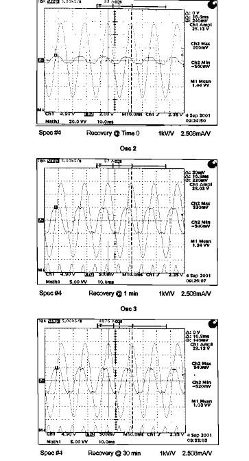
27 The following is an oscillographic record of the first transmission line discharge through the test sample. Shot 1 After successful completion of the (18) shot test, the sample was preheated to 60oC. and subjected to two additional transmission line discharges spaced one minute. The following is an oscillographic record of the 20th shot. Shot 20 After the 20th shot, the sample was energized at recovery voltage ( 9.83 kv RMS ). The sample remained energized until thermal stability was demonstrated. The following table summarizes the measured watts of the test sample during the recovery portion of the test. Applied Voltage Time Sample (kv RMS) (Minutes) Watts

28 The following oscillograms show section grading current measured at time 0, 1 minute, and 30 minutes. 5
29 The sample 10 ka 8/20 discharge voltage was measured before and after the duty cycle test. The measured values are summarized below. Before TLD Test Discharge Current=10.00 ka Discharge Voltage=27.77 kv After TLD Test Discharge Current=10.01 ka Discharge Voltage=27.76 kv CONCLUSION: The prorated test sample successfully completed the transmission line discharge test per IEEE C62.11 standard and demonstrated thermal stability when energized at recovery voltage. The 10 ka 8/20 discharge voltage was unchanged, within the allowable 10% acceptance limit. Disassembly revealed no evidence of physical damage to the test sample. Therefore, the Type PVI test sample has successfully fulfilled the transmission line discharge requirements of an Intermediate Class Arrester applied on a 161 kv system. 6
30 TYPE TEST REPORT No. EU1250-HR-09 DUTY CYCLE TEST CERTIFICATION This is to certify that the duty cycle design test has been successfully performed on Ohio Brass Type PVI Intermediate Class surge arrester. Michael G. Comber Manager Engineering Ohio Brass & Chardon Products Dennis W. Lenk P.E. Principal Engineer 10/27/03 Attachments 1
31 TITLE: Duty Cycle Test: DESIGN TEST REPORT PVI Intermediate Class Surge Arrester TEST OBJECTIVE: Section specifies that the 20-shot rated voltage and 2-shot recovery portion of the Duty Cycle test on Intermediate Class arresters be performed with 5 ka 8/20 lightning impulses. Tests were actually performed with 10 ka surges. TEST SAMPLE: As required by clause 7.2.2, prorated samples contained the minimum MOV mass per specified for the design. MCOV and rated voltages were also prorated per unit Vref to reflect the lowest margin case of the standard voltage ratings offered in this design. TEST PROCEDURE: The 9.42 kvrms MCOV test sample was energized at its kv rms rated voltage and subjected to twenty 10 ka, 8/20 discharges spaced at 1 minute increments. Following the twentieth impulse, the test section was placed in an oven at 60 C. After reaching 60 C, the sample was subjected to two 40 ka, 8/20 discharges. Within 5 minutes after the second high current discharge, the sample was energized at the prorated recovery voltage of 9.9 kv rms. Watts loss was monitored over a 30 minute period demonstrating thermal stability. TEST RESULTS: The following data summarizes the results of the duty cycle test. First Shot of 20 Shot Rated Voltage Duty Cycle Test 2
32 10 ka 8.1/18.8 Waveshape for 20 Shot Test 20 th Shot of 20 Shot Rated Voltage Duty Cycle Test 3
33 10.16kA 8.4/18.7 Waveshape for 2-Shot Test Oscillogram of 22 nd Shot Immediately after the 22 nd shot, the arrester section was energized at recovery voltage. The following oscillograms show section grading current measured at time 0, 1 minute, and 30 minutes. 4
34 5
35 The following table summarizes the results of the 20 shot rated duty cycle voltage test performed with 10 ka 8/20 initiating impulses. Shot No. Applied Voltage (kv rms ) Watts Grading Current (ma c ) 8/20 Impulse (ka) The following table summarizes the 21 st and 22 nd shots after sample preheating to 60 o C. Shot No. Applied Voltage (kv rms ) Watts Grading Current (ma c ) 8/20 Impulse (ka) The following table summarizes the recovery voltage portion of the duty cycle test. Time Applied Voltage Watts Grading Current (ma c ) (minutes) (kv rms )
36 Residual voltage at 10 ka was measured prior to and following the Duty Cycle test series. 10 ka IR Before Duty Cycle Tests = kv 10 ka IR After Duty Cycle Tests = kv Conclusion: The prorated test sample successfully completed Duty Cycle testing and demonstrated thermal stability during the recovery test. The 10 ka discharge voltage increased 0.1%, less than the acceptable 10% limit specified in Section of C Standard. Disassembly revealed no evidence of physical damage to the test sample. The PVI arrester successfully met the Duty Cycle requirements of the Intermediate Class arrester. 7
37 TYPE TEST REPORT No. EU1250-HR-10 TEMPORARY OVERVOLTAGE TEST CERTIFICATION This is to certify that the temporary overvoltage design test has been successfully performed on Ohio Brass Type PVI Intermediate Class surge arrester. Michael G. Comber Manager Engineering Ohio Brass & Chardon Products Dennis W. Lenk P.E. Principal Engineer 10/27/03 Attachments
38 DESIGN TEST REPORT PVI Intermediate Class Surge Arrester TITLE: Temporary over-voltage tests (TOV): TEST SAMPLES: Temporary over-voltage tests were performed per clause 8.12 of IEEE Standard C Tests were performed per Intermediate Class arrester requirements using five prorated test sections. Prorated sections were used to facilitate testing of the lowest MOV mass, highest stressed arrester rating at voltages within available laboratory facility capabilities. TEST PROCEDURE: Per clause , each prorated sample was tested within five of the six designated time ranges a - f, spanning over-voltage durations of.01-10,000 seconds. Per clause , the tests were performed demonstrating TOV capability of the design under "no prior duty" conditions. For each TOV voltage setting, the test circuit applied voltage to the sample (preheated to 60 o C) for a time duration sufficient to exceed that claimed on the "no prior duty" curve. TOV voltage was superimposed over recovery voltage such that when TOV was removed, there was no delay prior to application of recovery voltage. Recovery voltage was applied for 30 minutes to demonstrate thermal stability. TEST RESULTS: Tests were successfully completed on five PVI prorated samples in five specified time ranges. Each sample demonstrated thermal stability after TOV exposure having no signs of physical damage during inspection. Residual voltage at 10 ka measured prior to and following the complete TOV test series verified characteristics remained unchanged within acceptable limits. The following table summarizes the results of the TOV test program and applies to PVI arresters through 144 kv rating. TOV DURATION NO PRIOR DUTY TOV PRIOR DUTY TOV (SECONDS) (PER UNIT MCOV) (PER UNIT MCOV) The following curve plots the individual no prior duty data points on the claimed TOV capability curve. 2
39 PVI 60 HZ TEMPORARY OVERVOLTAGE CAPABILITY CURVE PER IEEE C62.11 STANDA Per Unit Times MCOV NO PRIOR DUTY CURVE PRIOR DUTY CURVE Time-Seconds Data Points No Prior Duty Durve Prior Duty Curve 3
40 TYPE TEST REPORT No. EU 1250-HR-11 PRESSURE RELIEF TEST CERTIFICATION This is to certify that the pressure relief design test has been successfully performed on Ohio Brass Type PVI Intermediate Class surge arrester. Michael G. Comber Manager Engineering Ohio Brass & Chardon Products Dennis W. Lenk P.E. Principal Engineer 10/27/03 Attachments
41 DESIGN TEST REPORT PVI Intermediate Class Surge Arrester TITLE: Pressure Relief Test For Polymer Housed Intermediate Class Arrester: TEST OBJECTIVE: Pressure relief tests were performed on the Type PVI polymerhoused Intermediate Class arrester per Section 8.13 of IEEE C Standard. TEST SAMPLES: Tests were performed on fusewire shorted arresters. Pressure relief tests were performed on the longest mechanical section, as required in Section of the standard. TEST PROCEDURE: A reduced voltage test source was used during the high current pressure relief test. Because of this, the claimable high current symmetrical current is the lesser of the Peak I/2.6, the Asymmetrical I/1.55, or the actual symmetrical current. TEST RESULTS: The following table summarizes both the low and high current pressure relief tests. The high current pressure relief was performed on the longest 42 kv MCOV arrester section. Sample MCOV Mode of Failure Test Volt kvc Peak kac Asym ka rms Symm ka rms Calculate Symm. KA rms Fault Durat Cycles Description of Test Sample After Pres relief test 17 Puncture Module Intact Polymer Hsg in Position with 1 Vertical tear 17 Shorted Module Intact Polymer Hsg in position with 1 Vertical tear 42 Puncture Module Intact Polymer Hsg Separated CONCLUSION: Two tests arresters successfully passed the 600 amp low current requirement. The test arrester assembled with the longest mechanical unit met the test evaluation criteria as specified in Section of IEEE C Standard. In all tests, the arrester module remained intact after the completion of each test. The flexible polymer housing wall section split or separated, as intended, on all samples to allow venting of internal arcing gases to the outside of the arrester. In all cases, flames associated with the fault current test extinguished immediately after completion of the test, well within the allowed 2 minute duration. These tests have demonstrated the capability of the PVI arrester design to discharge a maximum claimable 61.5 ka rms symmetrical fault current using the test procedure defined in Section 8.13 of IEEE C Standard. 2
42 TYPE TEST REPORT No. EU1250-HR-12 MAXIMUM DESIGN CANTILEVER LOAD-STATIC TEST CERTIFICATION This is to certify that the maximum design cantilever load-static design test has been successfully performed on Ohio Brass Type PVI Intermediate Class surge arrester. Michael G. Comber Manager Engineering Ohio Brass & Chardon Products Dennis W. Lenk P.E. Principal Engineer 10/27/03 Attachments
43 DESIGN TEST REPORT PVI Intermediate Class Surge Arrester TITLE: Maximum Design Cantilever Load-Static Test TEST SAMPLES: The maximum design cantilever load (static) test was performed on a PVI 19.5 kv MCOV arrester. Tests were performed to validate the claimed 5000 inch-pound continuous cantilever rating. TEST PROCEDURE: Testing was performed per the procedures specified in Section of IEEE Std C The test arrester was rigidly mounted at its base and top end loading applied to develop 5000 inch-pound cantilever load. With the arrester under load, the arrester was energized at 1,05 times MCOV and internal ionization was measured. Successive testing was performed at 0 o, 90 o, 180 o, and 270 o. Per paragraph d), the arrester was placed inside a thermal cycling oven for 96 hours and subjected to a combination of 5000 inch-pound load rotations and temperature excursions as specified in Figure 3 of C Standard. After completion of the thermal cycling test, the IIV was remeasured in the four quadrants with the arrester energized at 1.05 times MCOV. TEST RESULTS: The following table summarizes the results of the IIV tests with 1.3 and 2.0 microvolts of circuit background noise, respectively, for before and after testing. Arrester # Direction of Applied 1200 in-lb Load (Degrees) IIV Testing Prior to and After Thermal Cycling 1.05 Times MCOV before Thermal Cycling (Microvolts) 1.05 Times MCOV after Thermal Cycling (Microvolts) CONCLUSION: Per Section , the internal ionization levels measured with the arrester loaded to 5000 inch-pounds were unchanged as a result of the thermal cycling test. Visual examination revealed no evidence of mechanical damage. The above tests validated the electrical integrity of the PVI arrester assembled with a 3-lug base end casting when loaded to the 5000 inch-pound continuous cantilever rating 2
44 TYPE TEST REPORT No. EU 1250-HR-13 VERIFICATION OF THERMALLY PRORATED SECTION CERTIFICATION This is to certify that verification tests demonstrating thermal equivalency were successfully performed on Ohio Brass Type PVI Intermediate Class surge arrester. Michael G. Comber Manager Engineering Ohio Brass & Chardon Products Dennis W. Lenk P.E. Principal Engineer 10/27/03 Attachments
45 DESIGN TEST REPORT PVI Intermediate Class Surge Arrester TITLE: Verification of thermally prorated arrester section: OBJECTIVE: Tests were performed per IEEE Standard C62.11 to validate the thermally prorated arrester section used on specified durability tests. TEST SAMPLES: The longest PVI module was assembled with thermocouples located in the bottom quarter, center, and upper quarter locations. The average temperature of the three thermocouples was compared with the temperature of the thermally prorated section. In both cases, thermocouples were located between two adjacent MOV disks. The longest module was chosen to represent the highest percent MOV mass per unit arrester length. TEST PROCEDURE: The full size arrester and prorated arrester section were heated to the target temperature using a 60 Hz source. The target temperature was C with test lab ambient at 20 +/- 3 C. The duration of applied voltage was 10 minutes. Within 1 minute after voltage was disconnected, the cooling rate of each test sample was monitored at 5 minute intervals. CONCLUSION: Upon achieving the desired target temperature, the thermocouples were attached to a data logger and temperature was monitored continuously for 120 minutes. Figure 1 contains cooling curves verifying the longest PVI module arrester cooling rate was always greater than the prorated thermal test section. Figure 1 Curves Verifying the Thermal Cooling Equivalency of the PVI Arrester to the Thermally Prorated Section Cooling Time-Minutes PVI Arrester 15JUL01 PVI Prorated section 3JUN271 2
IEEE DESIGN TEST REPORT Report No. TD E00 Type PVR HD Riser Pole Distribution Class Surge Arrester
 IEEE DESIGN TEST REPORT Report No. TD 01 060 E00 Type PVR HD Riser Pole Distribution Class Surge Arrester This report records the results of the design tests made on Type PVR Riser Pole Distribution Class
UBC 26-2 Test Method for the Evaluation of Thermal Barriers. Contego International 7/16" OSB with Fire Barrier Latex
 UBC 26-2 Test Method for the Evaluation of Thermal Barriers Contego International 7/16" OSB with Fire Barrier Latex Project No. 16539-112809 November 27, 2002 Prepared for: Contego International 7991 West
TOSHIBA Industrial Magnetron E3328
 TOSHIBA E3328 is a fixed frequency continuous wave magnetron intended for use in the industrial microwave heating applications. The average output power is 3kW in the frequency range from 2450 to 2470
Jul03 Rev C EC
 Product Specification Coaxial BNC Solder Receptacle Connector 108-12079 10Jul03 Rev C EC 0990-0940-03 1. SCOPE 1.1. Content This specification covers the performance, tests and quality requirements for
TRANSMISSION ENGINEERING STANDARD TES-P , Rev. 0 TABLE OF CONTENTS 1.0 PURPOSE 2.0 SCOPE 3.0 CODES, STANDARDS AND REFERENCES
 TABLE OF CONTENTS 1.0 PURPOSE 2.0 SCOPE 3.0 CODES, STANDARDS AND REFERENCES 4.0 ORDER OF PRECEDENCE 5.0 SYSTEM PARAMETERS 5.1 Frequency 5.2 System Voltage 5.3 Short Circuit Rating 5.4 Insulation Levels
PERFORMANCE SPECIFICATION SHEET
 INCH-POUND MIL-PRF-19978/9C 11 March 2004 SUPERSEDING MIL-PRF-19978/9C 27 May 1999 PERFORMANCE SPECIFICATION SHEET CAPACITORS, FIXED, PLASTIC (OR PAPER-PLASTIC) DIELECTRIC, AXIAL-WIRE TERMINAL, TUBULAR
AMERICAN NATIONAL STANDARD
 Interface Practices Subcommittee AMERICAN NATIONAL STANDARD ANSI/SCTE 108 2018 Test Method for Dielectric Withstand of Coaxial Cable NOTICE The Society of Cable Telecommunications Engineers (SCTE) / International
Single output models feature wide-range output adjustability to meet a wide variety of standard and user-specific output voltage requirements.
 RoHS Lead-Solder-Exemption Compliant New 3.3 V and 5 V Output Models Universal Input 85-264 VAC Industry-Standard Footprint: 7.0" x 4.3" x 1.97" (177.8 x 109.2 x 50.0 mm) Input Transient & ESD Compliance
LED Driver Linear / area dimming industry. Driver LC 200W 1050mA UNV ADV IND ADVANCED series
 Driver LC 200W 1050mA UNV ADV IND ADVANCED series Product description Independent constant current LED Driver For dry, damp and wet locations Max. output power 200 W Up to 93.7 % efficiency For luminaires
American National Standard for Lamp Ballasts High Frequency Fluorescent Lamp Ballasts
 American National Standard for Lamp Ballasts High Frequency Fluorescent Lamp Ballasts Secretariat: National Electrical Manufacturers Association Approved: January 23, 2017 American National Standards Institute,
TeSys contactors. Model d. Type of contactor LC1- LC1- LC1- LC1- LC1-D115 & D09 D18 D25 D38 D40 D50 D95 LC1-D150 DT20 & DT25 DT32 & DT40
 Characteristics Type of contactor LC- LC- LC- LC- LC-D & D09 D8 D2 D38 D40 D0 D9 LC-D0 DT20 & DT2 DT32 & DT40 Environment Rated insulation voltage (Ui) Conforming to IEC 947-4-, overvoltage category III,
American National Standard for Electric Lamps - Fluorescent Lamps - Guide for Electrical Measures
 NEMA Standards Publication ANSI C78.375A-2014 American National Standard for Electric Lamps - Fluorescent Lamps - Guide for Electrical Measures National Electrical Manufacturers Association Revision of
1 Power Protection and Conditioning
 Power Protection and Conditioning MCR Hardwired Series Power Line Conditioning with Voltage Regulation The MCR Hardwired Series provides excellent noise filtering and surge protection to safeguard connected
STATE OF OHIO DEPARTMENT OF TRANSPORTATION SUPPLEMENTAL SPECIFICATION 872 LIGHT EMITTING DIODE TRAFFIC SIGNAL LAMP UNITS JULY 19, 2002
 STATE OF OHIO DEPARTMENT OF TRANSPORTATION SUPPLEMENTAL SPECIFICATION 872 LIGHT EMITTING DIODE TRAFFIC SIGNAL LAMP UNITS JULY 19, 02 872.01 Description 872.02 Prequalification 872.03 Material Requirements
02/11/2015
 DIN Rail Mount 17.5 mm MUS/MUSF 80 AC/DC Part number 84872141 Control relays monitoring their own power supply - MUS : Over/undervoltage control Selectable latching (memory) function - MUSF : Over/undervoltage
SURGE PROTECTIVE DEVICES
 SURGE PROTECTIVE DEVICES COMPANY INTRODUCTION Bridex Singapore Pte Ltd is founded in 1978 as a manufacturer of instruments transformer for the Asian market. We are the first local electrical switchgear
ROAD COMMISSION FOR OAKLAND COUNTY SPECIAL PROVISION FOR LIGHT EMITTING DIODE (LED) VEHICLE TRAFFIC SIGNALS
 VEHICLE TRAFFIC SIGNALS") ROAD COMMISSION FOR OAKLAND COUNTY SPECIAL PROVISION FOR LIGHT EMITTING DIODE (LED) VEHICLE TRAFFIC SIGNALS RCOC/TOC: DD Page 1 of 9 RCOC12TOC820E a. General Requirements Furnish all labor, equipment,
ROAD COMMISSION FOR OAKLAND COUNTY SPECIAL PROVISION FOR LIGHT EMITTING DIODE (LED) VEHICLE TRAFFIC SIGNALS RCOC/TOC: DD Page 1 of 9 RCOC12TOC820E a. General Requirements Furnish all labor, equipment,
AMERICAN NATIONAL STANDARD
 Interface Practices Subcommittee AMERICAN NATIONAL STANDARD ANSI/SCTE 129 2017 Drop Passives: Bonding Blocks (Without Surge Protection) NOTICE The Society of Cable Telecommunications Engineers (SCTE) Standards
Soft starter, 66 A, V AC, Us= 24 V DC, with control unit, Frame size N. Function Soft starter for three-phase loads, with control unit
 DATASHEET - S811+N66N3S Delivery program Soft starter, 66 A, 200-600 V AC, Us= 24 V DC, with control unit, Frame size N Part no. S811+N66N3S Catalog No. 168978 Eaton Catalog No. S811PLUSN66N3S EL-Nummer
ORDERING Page 6 BASLER RELAY STANDARDS, DIMENSIONS, ACCESSORIES Request bulletin SDA
 BE1-59NC CAPACITOR NEUTRAL OVERVOLTAGE RELAY The BE1-59NC Capacitor Neutral Overvoltage Relay provides sensitive protection for capacitor banks. ADDITIONAL INFORMATION INSTRUCTION MANUAL ADVANTAGES Helps
ENGINEERING COMMITTEE Interface Practices Subcommittee AMERICAN NATIONAL STANDARD ANSI/SCTE
 ENGINEERING COMMITTEE Interface Practices Subcommittee AMERICAN NATIONAL STANDARD ANSI/SCTE 60 2015 Test Method for Interface Moisture Migration Double Ended NOTICE The Society of Cable Telecommunications
High Temperature Operation of Extruded Distribution Cable Systems. White Paper
 High Temperature Operation of Extruded Distribution Cable Systems White Paper October 2018 NOTICE The information contained herein is, to our knowledge, accurate and reliable at the date of publication.
3M Sensored Termination (15 kv) QX-T15I-vi1-E
 QX-T15I-vi1-E") 3M Sensored Termination () QX-T15I-vi1-E Data Sheet May 2016 Kit Contents: Each kit contains sufficient quantities of the following materials to make three single-phase terminations. 31" (REF) One piece
3M Sensored Termination () QX-T15I-vi1-E Data Sheet May 2016 Kit Contents: Each kit contains sufficient quantities of the following materials to make three single-phase terminations. 31" (REF) One piece
ORDERING Page 6 STANDARDS, DIMENSIONS and ACCESSORIES Request bulletin SDA
 BE1-59NC CAPACITOR NEUTRAL OVERVOLTAGE RELAY The BE1-59NC Capacitor Neutral Overvoltage Relay provides sensitive protection for capacitor banks. ADVANTAGES Helps avoid cascading capacitor failures. Sensing
ASTM E a Fire Tests Of Building Construction and Materials *Modified SMALL-SCALE TEST OF FIREBLOCKING MATERIALS
 ASTM E 119-00a Fire Tests Of Building Construction and Materials *Modified SMALL-SCALE TEST OF FIREBLOCKING MATERIALS Project No. 16094-111638 * At this time, no specific test for evaluating fireblocking
SPECIAL SPECIFICATION 6735 Video Optical Transceiver
 2004 Specifications CSJ 0924-06-244 SPECIAL SPECIFICATION 6735 Video Optical Transceiver 1. Description. This Item governs the furnishing and installation of Video optical transceiver (VOTR) in field location(s)
PERFORMANCE SPECIFICATION SHEET CONNECTORS, PLUGS, ELECTRICAL, COAXIAL RADIO FREQUENCY, (SERIES BNC (CABLED), PIN CONTACT, CLASS 2)
, PIN CONTACT, CLASS 2)") INCH-POUND MIL-PRF-39012/16H 16 November 2006 SUPERSEDING MIL-PRF-39012/16G 26 September 1994 PERFORMANCE SPECIFICATION SHEET CONNECTORS, PLUGS, ELECTRICAL, COAXIAL RADIO FREQUENCY, (SERIES BNC (CABLED),
INCH-POUND MIL-PRF-39012/16H 16 November 2006 SUPERSEDING MIL-PRF-39012/16G 26 September 1994 PERFORMANCE SPECIFICATION SHEET CONNECTORS, PLUGS, ELECTRICAL, COAXIAL RADIO FREQUENCY, (SERIES BNC (CABLED),
Medium and High Voltage Circuit Breakers Characteristic Time Quantities of the Circuit Breaker with Applications
 Workshop 6: Maintenance and monitoring Medium and High Voltage Circuit Breakers Characteristic Time Quantities of the Circuit Breaker with Applications Alexander Herrera OMICRON electronics GmbH 3 December
TRISHALA ELECTROLYTICS PVT LTD BANGALORE
 P TRISHALA ELECTROLYTICS PVT LTD BANGALORE- 560044 AC MOTOR START ALUMINIUM ELECTROLYTIC CAPACITORS (Aluminum Body / Bakelite (Phenolic) Body) Scope Aluminum electrolytic Motor Start Capacitors are used
GV3P80 TeSys GV3P thermal-magn motor circuit breaker 70-80A EverLink
 Characteristics TeSys GV3P thermal-magn motor circuit breaker 70-80A EverLink Main Range Product name Device short name Product or component type Device application Trip unit technology Complementary Poles
CARLITE grain orien TEd ELECTRICAL STEELS
 CARLITE grain ORIENTED ELECTRICAL STEELS M-3 M-4 M-5 M-6 Product d ata Bulletin Applications Potential AK Steel Oriented Electrical Steels are used most effectively in transformer cores having wound or
Table of Contents. Amplifiers Broadband Telecommunications Line Extender [BLE-75**] FEATURES
![Table of Contents. Amplifiers Broadband Telecommunications Line Extender [BLE-75**] FEATURES](/thumbs/90/101623555.jpg "Table of Contents. Amplifiers Broadband Telecommunications Line Extender [BLE-75**] FEATURES") Table of Contents Amplifiers Broadband Telecommunications Line Extender [BLE-75**] FEATURES 750 MHz Power Doubling Technology 60/90 V Powering Surge Tolerant 29 db Operational Gain Bode Equalization (thermal
Table of Contents Amplifiers Broadband Telecommunications Line Extender [BLE-75**] FEATURES 750 MHz Power Doubling Technology 60/90 V Powering Surge Tolerant 29 db Operational Gain Bode Equalization (thermal
HY-32 Deuterium Triode Thyratron
 ENGAGE. ENABLE. EXCEL. HY-32 Description The HY-32 is a deuterium-filled, triode thyratron. The deuterium fill gas facilitates reliable operation at higher voltages and low to moderate repetition rates
LED Driver Compact dimming
 Driver CA 15W 180-350mA flexc PH-C SR ADV ADVACED series Product description Dimmable constant current ED Driver (SEV) Independent ED Driver with cable clamps Selectable output current between 180, 250
MILLITARY SPECIFICATION SHEET
 INCH-POUND MILLITARY SPECIFICATION SHEET 10 November 2000 SUPERSEDING MIL-R-6106/14B 10 March 1989 RELAY, ELECTRIC, PERMANENT DRIVE, 50 AMP, SPDT (DB) DOUBLE MAKE DOUBLE BREAK AUXILIARY CONTACTS (5 AMP),
Protective function Systems, cable, selectivity and generator protection. i 2 t constant function: switchable. I r A
 DATASHEET - NZMN3-VE630 Circuit-breaker, 3p, 630A Part no. NZMN3-VE630 Catalog No. 259133 EL-Nummer (Norway) 0004358791 Similar to illustration Delivery program Product range Circuit-breaker Protective
API Witness Report Perforator System Registration Page 1 of 5 General Information
 API Witness Report Perforator System Registration Page 1 of 5 General Information 1. CHARGE SELECTION Mandatory activity to witness, API RP 19B, Section 1.4 6-Quantity of Charges Available for Selection
COMPOSITE VIDEO LUMINANCE METER MODEL VLM-40 LUMINANCE MODEL VLM-40 NTSC TECHNICAL INSTRUCTION MANUAL
 COMPOSITE VIDEO METER MODEL VLM- COMPOSITE VIDEO METER MODEL VLM- NTSC TECHNICAL INSTRUCTION MANUAL VLM- NTSC TECHNICAL INSTRUCTION MANUAL INTRODUCTION EASY-TO-USE VIDEO LEVEL METER... SIMULTANEOUS DISPLAY...
GA A26497 SOLID-STATE HIGH-VOLTAGE CROWBAR UTILIZING SERIES-CONNECTED THYRISTORS
 GA A26497 SOLID-STATE HIGH-VOLTAGE CROWBAR by J.F. Tooker, P. Huynh, and R.W. Street JUNE 2009 DISCLAIMER This report was prepared as an account of work sponsored by an agency of the United States Government.
Capacitors and banks 50 Hz 0 400/415 V network voltage
 Capacitors and anks 50 Hz 0 Varplus M capacitors 051327 E92427 E92428 E89596 E89598 The range of Varplus M modular capacitors consists of the Varplus M1 and Varplus M4 capacitors, whose different assemly
CCC & IR/DWV TESTING REPORT PART DESCRIPTION SFSDT-20-XX-GF S. Mated with TFM S-D-A
 Project Number: Tracking Code: TC099-SFSDT-2277_ReportRev1 Requested by: Brian Perry Date: 10/7/2009 Product Rev: H Lot #: 1 Tech: Tony Wagoner & Rodney Riley Eng: Troy Cook Qty to test: 16 Test Start:
PERFORMANCE SPECIFICATION SHEET CONNECTORS, PLUGS, ELECTRICAL, COAXIAL RADIO FREQUENCY, (SERIES TNC (CABLED), PIN CONTACT, RIGHT ANGLE, CLASS 2)
, PIN CONTACT, RIGHT ANGLE, CLASS 2)") INCH-POUND MIL-PRF-39012/30H 15 March 2018 SUPERSEDING MIL-PRF-39012/30H w/amendment 3 15 April 2017 PERFORMANCE SPECIFICATION SHEET CONNECTORS, PLUGS, ELECTRICAL, COAXIAL RADIO FREQUENCY, (SERIES TNC
INCH-POUND MIL-PRF-39012/30H 15 March 2018 SUPERSEDING MIL-PRF-39012/30H w/amendment 3 15 April 2017 PERFORMANCE SPECIFICATION SHEET CONNECTORS, PLUGS, ELECTRICAL, COAXIAL RADIO FREQUENCY, (SERIES TNC
MAP110 AC-DC Series Data Sheet
 Description Single-Output Model Selection VOLTAGE RANGE OUTPUT CURRENT OUTPUT CURRENT REGULATION REGULATION %p-p (NOTE 1) ACCURACY MAP110-1005 5V 4.95V to 5.50 16A 2 0.2% 1% 1% 5.09V to 5.11V MAP110-1012
SECTION MEDIUM VOLTAGE CABLE INSTALLATION. 1. Section Underground Ducts and Manholes.
 SECTION 33 71 49.23 MEDIUM VOLTAGE CABLE INSTALLATION PART 1 GENERAL 1.1 SCOPE A. Work included in this Section: Medium Voltage Cable (4 kv and 12 kv) Installation and Termination. Removal and return of
Specifications. Reference Documentation. Performance Conditions
 The material in this section is organized into two main groupings: the specification tables and the supporting figures. The specification tables include: 1. PAL general and test signal specifications 2.
Description Set value in neutral conductor is synchronous with set value Ir of main pole. R.m.s. value measurement and thermal memory CSA 100
 DATASHEET - NZMN3-4-AE400 Circuit-breaker, 4p, 400A Part no. NZMN3-4-AE400 Catalog No. 265891 Similar to illustration EL-Nummer (Norway) 0004358857 Delivery program Product range Circuit-breaker Protective
INCH-POUND MIL-PRF-39012/29H w/amendment 3 25 January 2018 SUPERSEDING MIL-PRF-39012/29H w/amendment 2 21 November 2016
 INCH-POUND MIL-PRF-39012/29H 25 January 2018 SUPERSEDING MIL-PRF-39012/29H w/amendment 2 21 November 2016 PERFORMANCE SPECIFICATION SHEET CONNECTORS, RECEPTACLE, ELECTRICAL, COAXIAL, RADIO FREQUENCY, (SERIES
4617 Super Power Triode
 4617 Super Power Triode Matrix-Oxide-Type Cathode DoubIe-Ended Terminal Configuration for Symmetrical Circuity Liquid Cooled Peak Power Output - 8 MW The BURLE-4617 is a water-cooled super-power triode
AMERICAN NATIONAL STANDARD
 ENGINEERING COMMITTEE Interface Practices Subcommittee AMERICAN NATIONAL STANDARD ANSI/SCTE 153 2008 Drop Passives: Splitters, Couplers and Power Inserters NOTICE The Society of Cable Telecommunications
1C.5.1 Voltage Fluctuation and Flicker
 2 1 Ja n 1 4 2 1 J a n 1 4 Vo l.1 -Ge n e r a l;p a r tc-p o we r Qu a lity 1. Scope This document contains guidelines regarding maximum acceptable levels of voltage fluctuation and light flicker in the
Digital Delay / Pulse Generator DG535 Digital delay and pulse generator (4-channel)
") Digital Delay / Pulse Generator Digital delay and pulse generator (4-channel) Digital Delay/Pulse Generator Four independent delay channels Two fully defined pulse channels 5 ps delay resolution 50 ps
Digital Delay / Pulse Generator Digital delay and pulse generator (4-channel) Digital Delay/Pulse Generator Four independent delay channels Two fully defined pulse channels 5 ps delay resolution 50 ps
OT 100/ /700 P5
 OT 100/120 277/700 P5 OPTOTRONIC Outdoor Constant current LED drivers Areas of application _ Street and urban lighting _ Industry _ Suitable for luminaires of protection class I Product benefits _ High
SPECIAL SPECIFICATION 6911 Fiber Optic Video Data Transmission Equipment
 2004 Specifications CSJ 3256-02-079 & 3256-03-082 SPECIAL SPECIFICATION 6911 Fiber Optic Video Data Transmission Equipment 1. Description. Furnish and install Fiber Optic Video Data Transmission Equipment
I r A Protection against direct contact Finger and back of hand proof to VDE 0106 Part 100
 DATASHEET - NZMH2-A100 Circuit-breaker, 3p, 100A Part no. NZMH2-A100 Catalog No. 259099 Similar to illustration Delivery program Product range Circuit-breaker Protective function System and cable protection
Catalogue Ignitors and power switches for HID
 Catalogue 2012 Ignitors and power switches for HID Overview Product overview Ignitor matrix Standards Page 6 Page 7 Page 8 Product information Ignitors and power switches for HID Page 9 Superimposed-pulse
I/A Series Hardware Fiber Optic LAN Converter
 I/A Series Hardware PSS 21H-7F3 B4 The provides bidirectional conversion between coaxial and fiber optic media. The converter is compatible with existing I/A Series system hardware, utilizes industry standard
Principles of Electrostatic Chucks 6 Rf Chuck Edge Design
 Principles of Electrostatic Chucks 6 Rf Chuck Edge Design Overview This document addresses the following chuck edge design issues: Device yield through system uniformity and particle reduction; System
Series CDP2 Definite Purpose Contactors
 Series CDP2 Definite Purpose Contactors High performance economical contactors for commercial applications up to 90 Sprecher + Schuh s Definite Purpose contactors are ideal for commercial applications
SPECIAL SPECIFICATION 1291 Fiber Optic Video Data Transmission Equipment
 1993 Specifications CSJ 0500-01-117 SPECIAL SPECIFICATION 1291 Fiber Optic Video Data Transmission Equipment 1. Description. This Item shall govern for the furnishing and installation of Fiber Optic Video
MASTR II BASE STATION 12/24V POWER SUPPLY 19A149979P1-120 VOLT/60 Hz 19A149979P2-230 VOLT/50 Hz
 Mobile Communications MASTR II BASE STATION 12/24V POWER SUPPLY 19A149979P1-120 VOLT/60 Hz 19A149979P2-230 VOLT/50 Hz CAUTION THESE SERVICING INSTRUCTIONS ARE FOR USE BY QUALI- FIED PERSONNEL ONLY. TO
Lecture 17 Microwave Tubes: Part I
 Basic Building Blocks of Microwave Engineering Prof. Amitabha Bhattacharya Department of Electronics and Communication Engineering Indian Institute of Technology, Kharagpur Lecture 17 Microwave Tubes:
PERFORMANCE SPECIFICATION SHEET CONNECTORS, PLUGS, ELECTRICAL, COAXIAL RADIO FREQUENCY, (SERIES BNC (CABLED), PIN CONTACT, CLASS 2)
, PIN CONTACT, CLASS 2)") PERFORMANCE SPECIFICATION SHEET MIL-PRF-39012/16H 03 January 2017 SUPERSEDING MIL-PRF-39012/16H w/amendment 1 20 April 2009 CONNECTORS, PLUGS, ELECTRICAL, COAXIAL RADIO FREQUENCY, (SERIES BNC (CABLED),
PERFORMANCE SPECIFICATION SHEET MIL-PRF-39012/16H 03 January 2017 SUPERSEDING MIL-PRF-39012/16H w/amendment 1 20 April 2009 CONNECTORS, PLUGS, ELECTRICAL, COAXIAL RADIO FREQUENCY, (SERIES BNC (CABLED),
LITE-ON TECHNOLOGY CORPORATION
 Features * Lead (Pb) free product RoHS compliant. * Low power consumption. * High efficiency. * Versatile mounting on p.c. board or panel. * I.C. compatible/low current requirement. * Popular T-1 diameter.
GV2P05. Main. Device short name. Device application
 Product datasheet Characteristics GV2P05 Main Range Product name Device short name Product or component type Device application Trip unit technology TeSys TeSys GV2 GV2P Circuit breaker Motor Thermal-magnetic
R&S ZVA-Zxx Millimeter-Wave Converters Specifications
 R&S ZVA-Zxx Millimeter-Wave Converters Specifications Data Sheet Version 19.00 CONTENTS Definitions... 3 General information... 4 Specifications... 5 Test port... 5 Source input (RF IN)... 5 Local oscillator
Toronto Hydro - Electric System
 Toronto Hydro - Electric System FIT Commissioning Requirements and Reports Comments and inquiries can be e-mailed to: FIT@torontohydro.com Customers without e-mail access can submit through regular mail
SMD LED Product Data Sheet LTST-T680UWET Spec No.: DS Effective Date: 09/26/2014 LITE-ON DCC RELEASE
 Product Data Sheet Spec No.: DS22-2014-0070 Effective Date: 09/26/2014 Revision: A LITE-ON DCC RELEASE BNS-OD-FC001/A4 LITE-ON Technology Corp. / Optoelectronics No.90,Chien 1 Road, Chung Ho, New Taipei
4.9 BEAM BLANKING AND PULSING OPTIONS
 4.9 BEAM BLANKING AND PULSING OPTIONS Beam Blanker BNC DESCRIPTION OF BLANKER CONTROLS Beam Blanker assembly Electron Gun Controls Blanker BNC: An input BNC on one of the 1⅓ CF flanges on the Flange Multiplexer
GV2ME086 TeSys GV2 - Circuit breaker - thermal-magnetic A - lugs-ring terminals
 Product data sheet Characteristics GV2ME086 TeSys GV2 - Circuit breaker - thermal-magnetic - 2.5...4 A - lugs-ring terminals Main Range Product name Device short name Device application Trip unit technology
Form C: Type Test Verification Report
 Form C: Type Test Verification Report Type Approval and Manufacturer declaration of compliance with the requirements of G98. This form should be used when making a Type Test submission to the Energy Networks
Surge-Gap Drop Amplifier 1 GHz with 42/54 MHz Split
 Taps & Passives Surge-Gap Drop Amplifier 1 Gz with 42/54 Mz Split Description As data, advanced video, and voice services are made available over broadband networks, the demand for signal level at the
Form C: Type Test Verification Report
 Form C: Type Test Verification Report Type Approval and Manufacturer declaration of compliance with the requirements of G98. This form should be used when making a Type Test submission to the Energy Networks
Definitions. Common Corridor:
 Definitions Common Corridor: Contiguous right-of-way or two parallel right-of-ways with structure centerline separation less than the longest span length of the two transmission circuits at the point of
Magnecraft Power Relays
 Description DPST-NO, 30 A; DPDT, 30 A (NO) / 3 A (NC) Description The series power relays offer a small package size and features Class F insulation for a maximum coil temperature of 55 C (3 F). These
Drop Passives: Splitters, Couplers and Power Inserters
 ENGINEERING COMMITTEE Interface Practices Subcommittee AMERICAN NATIONAL STANDARD ANSI/SCTE 153 2016 Drop Passives: Splitters, Couplers and Power Inserters NOTICE The Society of Cable Telecommunications
SMD LED Product Data Sheet LTW-006DCG-5 Spec No.: DS Effective Date: 11/30/2010 LITE-ON DCC RELEASE
 SMD LED Product Data Sheet LTW-006DCG-5 Spec No.: DS22-2010-0293 Effective Date: 11/30/2010 Revision: - LITE-ON DCC RELEASE BNS-OD-FC001/A4 LITE-ON Technology Corp. / Optoelectronics No.90,Chien 1 Road,
Medium Weight Shock and Vibration Test Report on 3 x 1.5 x 8 Pump with 30 HP Motor for Sims Pump Valve Company, Inc. Hoboken, NJ
 Test Report No. 10490.1 No. of Pages 16 Medium Weight Shock and Vibration Test Report on 3 x 1.5 x 8 Pump with 30 HP Motor for Sims Pump Valve Company, Inc. Hoboken, NJ NU LABORATORIES, INC. 312 Old Allerton
Luckylight Package Warm White Chip LED. Technical Data Sheet. Part No.: S150W-W6-1E
 126 Package Warm White Chip LED Technical Data Sheet Part No.: S15W-W6-1E Spec No.: S15 Rev No.: V.3 Date: Jul./1/26 Page: 1 OF 11 Features: Package in 8mm tape on 7 diameter reel. Compatible with automatic
LC1D12P7 TeSys D contactor - 3P(3 NO) - AC-3 - <= 440 V 12 A V AC coil
 - AC-3 - <= 440 V 12 A V AC coil") Characteristics TeSys D contactor - 3P(3 NO) - AC-3 -
Characteristics TeSys D contactor - 3P(3 NO) - AC-3 -
LC1D25G7 TeSys D contactor - 3P(3 NO) - AC-3 - <= 440 V 25 A V AC coil
 - AC-3 - <= 440 V 25 A V AC coil") Product data sheet Characteristics LC1D25G7 TeSys D contactor - 3P(3 NO) - AC-3 -
Product data sheet Characteristics LC1D25G7 TeSys D contactor - 3P(3 NO) - AC-3 -
LC1D09B7 TeSys D contactor - 3P(3 NO) - AC-3 - <= 440 V 9 A - 24 V AC coil
 - AC-3 - <= 440 V 9 A - 24 V AC coil") Product data sheet Characteristics LC1D09B7 TeSys D contactor - 3P(3 NO) - AC-3 -
Product data sheet Characteristics LC1D09B7 TeSys D contactor - 3P(3 NO) - AC-3 -
COHERENCE ONE PREAMPLIFIER
 COHERENCE ONE PREAMPLIFIER OWNER S MANUAL TABLE OF CONTENTS Introduction Features Unpacking Instructions Installation Phono Cartridge Loading Basic Troubleshooting Technical Specifications Introduction
PRINCIPLES AND APPLICATIONS
 GENERATION & NETWORK Digital Automation Measuring and Control Devices AMS7000 PROCOM The optimum operation of an electrical network depends particularly on the reliability and the availability of the protection,
Luckylight. 1.10mm Height 0805 Package. Warm White Chip LED. Technical Data Sheet. Part No.: S170W-W6-1E
 1.1mm Height 85 Package Warm White Chip LED Technical Data Sheet Part No.: S17W-W6-1E Spec No.: S17 Rev No.: V.3 Date: Jul./1/26 Page: 1 OF 11 Features: Luckylight Package in 8mm tape on 7 diameter reel.
PERFORMANCE SPECIFICATION SHEET
 INCH-POUND 5 October 2016 SUPERSEDING w/amendment 2 July 2016 PERFORMANCE SPECIFICATION SHEET CONNECTORS, PLUG, ELECTRICAL, COAXIAL, RADIO FREQUENCY, SERIES SMA (CABLED) PIN CONTACT, RIGHT ANGLE, CLASS
R&S ZVA-Zxx Millimeter-Wave Converters Specifications
 ZVA-Zxx_dat-sw_en_5214.2033.22_umschlag.indd 1 Data Sheet 13.00 Test & Measurement R&S ZVA-Zxx Millimeter-Wave Converters Specifications 28.01.2013 15:08:06 CONTENTS General information... 3 Definitions...
Detailed Design Report
 Detailed Design Report Chapter 4 MAX IV Injector 4.6. Acceleration MAX IV Facility CHAPTER 4.6. ACCELERATION 1(10) 4.6. Acceleration 4.6. Acceleration...2 4.6.1. RF Units... 2 4.6.2. Accelerator Units...
EA350. Generator Automatic Voltage Regulator Operation Manual
 Generator Automatic Voltage Regulator Operation Manual Self Excited Automatic Voltage Regulator For General Generators Compatible with Marathon SE350* * Use for reference purpose only and not a genuine
CR7000. CRT Analyzer & Restorer. Easily Test And Restore CRTs With The Most Complete Tests Available For Added Profit And Security.
 CR7000 CRT Analyzer & Restorer Easily Test And Restore CRTs With The Most Complete Tests Available For Added Profit And Security. S1 New Demands From Higher Performance CRTs Require New Analyzing Techniques
LC1D150G7 TeSys D contactor - 3P(3 NO) - AC-3 - <= 440 V 150 A V AC coil
 - AC-3 - <= 440 V 150 A V AC coil") Product data sheet Characteristics LC1D150G7 TeSys D contactor - 3P(3 NO) - AC-3 -
Product data sheet Characteristics LC1D150G7 TeSys D contactor - 3P(3 NO) - AC-3 -
Fluke 279 FC True-rms Thermal Multimeter
 TECHNICAL DATA Fluke 279 FC True-rms Thermal Multimeter 4 ways the Fluke 279 FC will make your job easier 1. Find the problem faster Scan with the thermal imager to find electrical problems rapidly and
WVR500 Waveform/Vector Monitor
 Service Manual WVR500 Waveform/Vector Monitor 070-8897-01 Warning The servicing instructions are for use by qualified personnel only. To avoid personal injury, do not perform any servicing unless you are
SnapStak Stackable Snap-In Cable Hanger Electrical and Mechanical Testing Performance
 SnapStak Stackable Snap-In Cable Hanger Electrical and Mechanical Testing Performance Table of Contents Introduction................................1 Axial pull test and horizontal shear test............2
WELDING CONTROL UNIT: TE 450 USER MANUAL
 j WELDING CONTROL UNIT: TE 450 USER MANUAL RELEASE SOFTWARE No. 1.50 DOCUMENT NUMBER: MAN 4097 EDITION: MARCH 1998 This page is left blank intentionally. 2 / 34 TABLE OF CONTENTS SUBJECTS PAGE WELDING
GENCOA Key Company Facts. GENCOA is a private limited company (Ltd) Founded 1995 by Dr Dermot Monaghan. Located in Liverpool, UK
 Founded 1995 by Dr Dermot Monaghan. Located in Liverpool, UK") GENCOA Key Company Facts GENCOA is a private limited company (Ltd) Founded 1995 by Dr Dermot Monaghan Located in Liverpool, UK Employs 34 people 6 design (Pro E 3D CAD) 4 process development & simulation
GENCOA Key Company Facts GENCOA is a private limited company (Ltd) Founded 1995 by Dr Dermot Monaghan Located in Liverpool, UK Employs 34 people 6 design (Pro E 3D CAD) 4 process development & simulation
I r A Protection against direct contact Finger and back of hand proof to VDE 0106 Part 100
 DATASHEET - NZMC1-A160 Circuit-breaker, 3p, 160A Part no. NZMC1-A160 Catalog No. 283296 Similar to illustration Delivery program Product range Circuit-breaker Protective function System and cable protection
INCH-POUND MIL-PRF-39012/28H w/amendment 4 25 January 2018 SUPERSEDING MIL-PRF-39012/28H w/amendment 3 15 April 2017
 INCH-POUND MIL-PRF-39012/28H 25 January 2018 SUPERSEDING MIL-PRF-39012/28H w/amendment 3 15 April 2017 PERFORMANCE SPECIFICATION SHEET CONNECTORS, RECEPTACLES, ELECTRICAL, COAXIAL, RADIO FREQUENCY, (SERIES
MILITARY SPECIFICATION SHEET
 INCH POUND MIL-S-22885/100A 16 May 2003 SUPERSEDING MIL-S-22885/100 (USAF) 27 August 1982 MILITARY SPECIFICATION SHEET SWITCH, PUSH BUTTON, ILLUMINATED, 4-LAMP, SPDT AND DPDT, 7.5 AMPERES, SILVER CONTACTS,
Medium Weight Shock and Vibration Test Report on 3 x 1 1/2 x 6 15 HP Pump for Sims Pump Valve Company Hoboken, NJ
 Report No. 10405.1 No. of Pages 16 Medium Weight Shock and Vibration Test Report on 3 x 1 1/2 x 6 15 HP Pump for Sims Pump Valve Company Hoboken, NJ NU LABORATORIES, INC. 312 Old Allerton Road, Annandale,
Signal Conditioners. Highlights. Battery powered. Line powered. Multi-purpose. Modular-style. Multi-channel. Charge & impedance converters
 Signal Conditioners Highlights Battery powered Line powered Multi-purpose Modular-style Multi-channel Charge & impedance converters Industrial charge amplifiers & sensor simulators PCB Piezotronics, Inc.