Parts and Maintenance Manual for GL50 Spiral Mixer
|
|
|
- Charles Nickolas Singleton
- 5 years ago
- Views:
Transcription

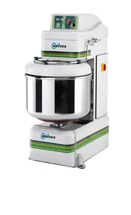


1 Parts and Maintenance Manual for GL50 Spiral Mixer
2 WARRANTY TERMS Validity: The warranty starts from the delivery date and lasts 2 months, if: The mixer was not damaged during transportation, and it was installed, commissioned, used and serviced as prescribed in this manual. It was not tampered with, modified and no unintended tools were installed on it. It did not undergo modifications or repairs carried out by the customer or third parties in an incompliant fashion or without the prior consent of the supplier. The following conditions constitute improper use of the mixer: Loading more than what is allowed or use of unsuitable ingredients. Cleaning with unsuitable tools or instruments that can scratch the bowl or damage the mixer or paint. Use of the mixer in unsuitable places. Warranty If the customer finds defects in the mixer, he must immediately inform the supplier, who will carry out a quick analysis of the lack of compliance and will establish the next steps to be taken with the customer. The customer must provide the needed time and opportunity to carry out modifications, improvements, repairs or the supply of spare parts which the supplier deems reasonably necessary. If this does not occur, the supplier will not be held liable. Parts subject to wear Some components are made to last far longer than that of a normal mixers life expectancy. Breakage or malfunctioning of these pieces depends on their use. They are therefore considered parts subject to wear and are not included in the warranty, unless they manifest evident defects in the parts or machinery. The parts subject to wear are: transmission belts, motors, bearings and bowl. 2 of 29
3 CONDITIONS FOR USE: Installation requirements: The mixer needs to be installed inside of a lit, ventilated building, on top of a solid and level support. Operating temperature range from 5 to 40 C with humidity no greater than 90%. Lighting: the light at disposal of the operator must comply with the type of work carried out, in relation to general lighting, according to the Standards in force. It must on any account be sufficient to read the controls and danger signs. Vibrations: in correct working conditions, vibrations do not create dangerous situations. Noise emissions: 70 dba for normal use. Electromagnetic environment: the machine has been built to work correctly in an industrial type of electromagnetic environment. Environments with risk of explosion: An atmosphere capable to being transformed into an explosive atmosphere due to room and/or operating conditions is defined a potentially explosive atmosphere. The mixer was not built to work in environments with potentially explosive atmospheres. MACHINE IDENTIFICATION: There is a plate on the back of the mixer which carries indications concerning the manufacturer, the type of machine, serial number, electrical features, and certifications. Storage of packed mixer: The mixer must be stored in a closed and covered place, on a smooth and solid surface protected from dust and filth, sheltered from atmospheric agents and hygienically safe. The temperatures must remain between 20 and +50 C, and humidity no greater than 90%. Installation: The mixer must stand in a vertical position, on a smooth surface sufficiently sturdy for the load (floor with resistance over 20 km/cm 2 ). ATTENTION. Do not make the mixer function only on wheels, always tighten the two supports until the wheels are fully lifted. Connection to electrical mains: The electrical connection must be carried out by a specialised electrician, according to the standards in force in the country where it is installed. Make sure that the voltage and frequency of the system are the same as those on the mixer identification plate. Incorrect connection makes the warranty void. Preservation of the machine: Storage before a long period out of service Clean the mixer thoroughly. Disconnect it from the electrical mains. If possible, put it back into its original packing. 3 of 29
4 Dimensions: 4 of 29
5 GREENLINE 50 MIXER CAPACITY CHART * Absorption Ratio (% AR) =water weight / Flour weight Note: GREENLINE 50 KG (0 LB) OF MIXING DOUGH PRODUCT FLOUR BATCH LOW GLUTEN FLOUR 60% AR 65 LB. 0 LB. BREAD, PIZZA DOUGH 60% AR 50 LB. 85 LB. BREAD, PIZZA DOUGH 50% AR 45 LB. 70 LB. BREAD,PIZZA DOUGH 40% AR 35 LB. 50 LB. PIE DOUGH 25 LB. 40 LB. BAGEL DOUGH 40 LB. 60 LB. Cold water causes dough to be stiff and hard to mix, increasing the load on the mixer transmission and motor. Never use ICE as solid part, melt it before add it into the mixer bowl. Pie Dough can be succesfully mixed in speed 5 of 29
6 TROUBLE SHOOTING GUIDE TROUBLE POSSIBLE CAUSE REMEDY. MIXER WILL NOT OPERATE. ELECTRICAL SERVICE DOWN.. CHECK ELECTRICAL SERVICE. REPLACE FUSE OR RESET CIRCUIT BREAKER AS NECESSARY.2 SAFETY GUARD NOT CLOSED.2 CLOSE SAFETY GUARD.3 TIMER NOT TURNED ON.3 TURN TIMER ON.4 EMERGENCY STOP BUTTON PUSHED.4 TURN EMERGENCY STOP BUTTON IN CLOCKWISE TO RELEASE.5 BURNED SWITCH CONTACTS.5 REPLACE OR CLEAN CONTACTS.6 BURNED OUT MOTOR.6 REMOVE, TEST, REPAIR OR REPLACE 2. MIXER RUNS BUT SPIRAL WILL NOT TURN. 2. BROKEN OR SLIPPING BELT 2. TIGHTEN OR REPLACE 2.2 BROKEN PULLEY 2.2 REPLACE 3. SPIRAL RUNS BUT BOWL WILL NOT RUN 3. BROKEN OR SLIPPING BOWL CHAIN 3. TIGHTEN OR REPLACE 4. ALL THE LIGHTS ARE ON BUT MIXER WILL NOT OPERATE 4. THE THERMAL PROBE STOPPED THE MOTORS BECAUSE THE DOUGH WAS TOO STIFF, OR THE MIXING TIME TOO LONG 4. WAIT 20 MINUTES UNTIL THE MOTORS TEMPERATURE GOES DOWN AND PRESS START BUTTON TO FINISH THE MIXING CYCLE 5. EXCESSIVE NOISE 5. GEARS NEED TO BE REPACKED WITH GREASE OR OIL LEVEL IS LOW. 5.2 NOTIFY A SERVICE AGENT 5.2 BADLY WORN OR FRYED DRIVE BELTS 5.2 REPLACE BELT 5.3 OVERLOAD MIXING BOWL. 5.3 ADJUST CONTENTS OF BOWL PER MIXING CAPACITIES TABLE 6 of 29
7 CONTROL OF INSTALLED SAFETY SYSTEMS AND ELECTRICAL SYSTEM: The installed safety systems and t he electrical system are subject to periodical checks carried out by a specialised electrician. Key of control intervals: (INTERVAL) d = daily. w = weekly. m = monthly. a = annually. Key of how to carry out the controls: (METHOD) O = observation: requires simple eye check (i.e. alarm light) F = Function: requires a physical control of the action (i.e. pressing the emergency button the mixer must stop) M = Measurements: requires a c ontrol with an appropriate instrument (i.e. control of earthing values). Master switch. Purpose: protection of power line. Function: this equipment separates the machinery from the mains, it is placed on the upright of the mixer, downstream the differential protection board. Safety micro switch of grid. Purpose: stop the machine temporarily. Function: by lifting the protection grid, the motor power supply interrupts, temporarily stopping the machine. To reset the machinery functioning, lower the grid and press the START button. Stop Circuit (emergency). Purpose: to stop the mixer immediately and unconditionally. Function: pressing the STOP button cuts the power supply to the mixer, stopping it totally and not systematically. To restore functioning of the machinery, the operator must release the emergency button and start the cycle once again by pressing the START button. Controls of system Periodically the mixer's automation functioning and earthing must be c hecked. The operating modes, safety functions, terminal board contacts need t o be controlled as well as the integrity of the cables, luminous LEDs and ear thing system. Control Interval Method a F Control Interval Method m F Control Interval Method m F Control Interval Method a F 7 of 29
8 CLEANING AND MAINTENANCE OPERATIONS: DO NOT CARRY OUT ANY MAINTENANCE OR CLEANING WITH ELECTRICITY CONNECTED All bearings and transmission parts are lubricated for life. Keep the mixer clean to avoid flour from depositing in the moving parts thus generating bothersome creaking and abnormal wear. To tension the belt, remove the upper casings, loosen the motor bolts and act on the appropriate register. Fasten the motor bolts, place the casings back and test the machine. Problems with the grid micro switch: remove the upper protection casing, adjust the micro switch position close the casing again and test the machine. *See Diagram below To tension the chain and the lower bowl drive chain, remove the lower casing (tilt the machine) and act on the appropriate registers. Replace the casing and test the machine *See Diagram below Electrical issues must be carried out by qualified electrician, with reference to the layouts attached at the end of the manual. Should a power cable be damaged, replace it with a H07RN/F cable with a 3x.5 mm 2 section Cleaning: the mixer is not water-proof. Do not wash it with running water/hose. Clean it with a moist cloth and neutral detergents. Do not use excess amounts of water as it is hard to remove from the bowl. 8 of 29
9 GREENLINE 50 Recommended Spare Parts Part Number Quantity Description S ML Bowl Chain (Linear Meter) S Black Feet S Bearing S Bearing S Waterproof Seal S Bearing RS 2 S Belt Poly V J83 8 Rib S Bearing RS 3 S Bearing RS 3 S Bearing RS 3 S Main Power Switch Group S Mobile Mixture Guard S Grid Micro Switch 9 of 29


10 CONTROL PANEL DESCRIPTIONS Set the standard control panel (built up to October 20) -Turn Power switch on based on right side of Greenline Mixers. -For some seconds you will see SGM 0 blinking into the digital displays. -After that you ll find the last programmed times on st and 2 nd displays. -If you don t need to change anything, you can press start button to start the mixing cycle. -The mixer will pass automatically from st to 2 nd speed until the end of both times. -If you need to set a new time configuration, please press select button. The st speed light should be blinking. Use + or - buttons to change st speed time, then press select to set the 2 nd one use + or - to regulate it and then press select button again to set the timers. -After that you can press start button and begin the mixing cycle. -The Manual key selector is made only for emergency cases to overpass the electrical chipboard and work manually in st or 2 nd speed. -Using the reverse Jog control, bowl and spiral will run counter clockwise but only until you keep the selector pressed. It could be helpful at the start-up (for small quantities of dough) or at the end of the mixing cycle for very wet dough. Do not use it for more than 60 seconds. 0 of 29
 -Press + or - buttons to choose the program number you would like to set. -Press select button to see the timers for st and 2 nd speed.")

11 SETTING THE NEW PROGRAMMABLE GREENLINE CONTROL PANEL Programmable Control Panel Greenline Version Turn the main power switch on, you should see the on the first display the program number blinking (ex. P.0 or P.02 etc ) -Press + or - buttons to choose the program number you would like to set. -Press select button to see the timers for st and 2 nd speed. -Hold select button for a few seconds until you see the st speed light on. -Use + or - buttons to set the st speed time then press select to set the second one. -You should see the second speed light on, set the timer for the second speed. -Press select again to set the timer. -Press start button to turn the mixer on. - st and 2 nd speed have two different displays. The st one has only three numbers: 2 for the minute and for the ten second increments. -The 2 nd one has 4 numbers: 2 for the minutes and 2 for the seconds. -When the timers countdown they pass automatically from st speed to 2 nd speed and stop at the end of the mixing cycle. -You do not need to reset the programs every time you switch off and on the mixer. of 29

12 Number Part Number Description Quantity S Control Panel Plate 2 S Electronic Timer Chipboard 3 S Emergency Stop Button 4 S Manual Key Selector 5 S Panel Decal 6 S0673 Waterproof Seal 7 S Reverse Direction Button 2 of 29
13 Mixer Lid Part Listing Illus Part No Description Qty S Fixed Mixture Guard 2 S Mobile Mixture Guard 3 S Stainless Steel Guard 4 S Fixed Mixture Guard Pivot 4 5 S Guard Pivot (Left) 6 S Guard Pivot (Right) 7 S Bushing Flange 2 8 S Microswitch Cam 9 S Eccentric Block 0 S Bracket S Guard Bushing Plate 3 2 S Bushing Plate 3 3 S Guard Microswitch 4 S Snap Ring Ø DIN 92 Screw TCEI M6 X DIN 933 Screw TE M8 X DIN 26 Washer M8 4 8 DIN 936 Low Nut M4 4 9 DIN 934 Nut M8 20 DIN 933 Screw TE M8 X 70 2 DIN 47 Elastic Ring Ø DIN 93 Pin M6 X DIN 92 Screw TCEI M8 X of 29
14 Mixer Lid of 29
15 Main Mixer Body Parts Listing Illus Part No Description Qty S Upper Cover 2 S Electronic Panel Plate 3 S Carter Support Pivot 4 4 S Rear Cover 5 S Bottom Cover 6 S Front Bottom Cover 7 S Stainless Plate 8 S73055 Countershaft 9 S73079 Block 2 0 S Wheel Plate 2 S Cable Clamp 2 S Main Power Switch 3 DIN 603 Carriage Bolt M5 X DIN 26 Washer M UNI 8842 Serrated Lock Washer M5 0 6 DIN 934 Nut M5 0 7 DIN 438 Screw M8 X DIN 92 Screw TCEI M5 X ISO 7380 Screw TCBEI M5 X DIN 933 Screw TE M0 X DIN 26 Washer M ISO 7380 Screw TCBEI M6 X DIN933 Screw TE M8 X DIN 26 Washer M DIN 799 Screw SPEI M0 X of 29
16 Main Mixer Body of 29
17 Lower Mixer Body Parts Listing S Foot Block 2 2 S40028 Feet 2 3 S73094 Wheels 4 4 S73058 Wheel Shaft 2 5 DIN 933 Screw TE M0 X DIN 26 Washer M of 29
18 Spiral Transmission Parts Listing Illus Part No Description Qty S AUTO-BLOCK RING-NUT 2 S BELT SPAX 0857 SPIRALE 4 3 S7305 SPIRAL PULLEY 4 S BEARING SPEACER 5 S BEARING RS 3 6 S SPIRAL BUSHING PLATE 7 S SPIRAL BUSHING 8 S BEARING RS 3 9 S SPIRAL BUSHING PLATE 0 S SPIRAL S SPIRAL FLANGE 2 S MOTOR PLATE 3 S005 SPIRAL MOTOR 4 S23005 STRETCHER 5 S73029 MOTOR PULLEY 6 S73087 TRANSMISSION BUSHING 7 S BELT POLYV 320J 80 SPIRALE 8 S BEARING RS3 9 S73050 NEUTRAL PULLEY 20 S BEARING RS 2 2 S NILOS RING S MIM RING S Return Shaft Pulley 24 S Belt Spa DIN 92 Screw TCEI M6x5 26 DIN 8842 Teeth Washer M6 27 DIN 26 Washer M6 28 DIN 933 Screw TE M8x Washer 8x32 30 DIN 933 Screw TE M8x DIN 26 Washer M8 32 DIN 934 Nut M DIN 988 Spacer 35x45x0,5 34 DIN 799 Screw SPEI M8x20 35 DIN 933 Screw TE M8x DIN 93 Pin M5x8 37 DIN 6885 A small plate 8x7x60 38 DIN 603 Squared screw M8x0 4 8 of 29
19 Spiral Transmission of 29
20 Bowl Transmission Parts Listing Illus Part No Description Qty 4735 BOWL BOWL SPACER BOWL SHAFT SPIRAL BUSHING PLATE SPIRAL FLANGE BEARING S BOWL BUSH BEARING SPIRAL BUSHING PLATE CROWN BOWL HUB BOWL CROWN BOWL CHAIN TENSION ROD PIVOT BOWL TENSION PLATE SMALL CROWN, CHAIN TRANSMISSION BEARING RS PIVOT BOWL PLATE BOWL PINION BEARING RS TENSIONING PLATE RETURN SHAFT TENSIONING PLATE MIM RING DIN 934 Nut M8 25 DIN 8842 TEETH WASHER M DIN 26 Washer M DIN 799 Screw SPEI M0x DIN 933 Screw TE M8x20 29 DIN 8842 TEETH WASHER M DIN 6885 A Small Plate 8x7x DIN 975 TENSION ROD M0 L=200 mm 2 32 DIN 587 CLOSED NUT M DIN 975 TENSION ROD M0 L=500 mm 34 DIN 93 Pin M0x DIN 47 SNAP ring Ø DIN 934 Nut M DIN 933 Screw TE M0x DIN 26 Washer M DIN 92 Screw TCEI M2x50 40 DIN 603 SQUARED SCREW M8x0 4 4 DIN 92 Screw TCEI M0x DIN 6885 A SMALL PLATE 8x7x50 43 DIN 988 SPACER 30x42x0,5 44 DIN 47 SNAP ring Ø30 20 of 29
21 Bowl Transmission Parts Drawing of 29
22 ELECTRICAL COMPONENTS PARTS AND CODES Part No Description Qty S Power Chipboard S Drive Chipboard S Main Power switch group S Emergency stop button S Reverse bowl rotation button group S Manual Key selector GL S Microswitch group for bowl's guard S0673 Control panel water proof seal S GreenLine panel decal S Control Panel Plate 22 of 29

23 Greenline 50 Electrical Diagrams 23 of 29
24 24 of 29
25 25 of 29
26 26 of 29
27 27 of 29
28 28 of 29
29 Obligations of informing users Information model for users of professional products INFORMATION FOR USERS In compliance with art. 3 of the Legislative Decree of July 25, 2005, n. 5 Implementing of Directives 2002/95/EC, 2002/96/EC and 2003/08/EC, relative to the reduction of the use of hazardous substances in electrical and electronic appliances as well as disposal of waste The symbol of the barred waste bin on the appliance or its packaging indicates that the product at the end of its useful life it must be disposed of separately from other waste. 29 of 29
Tube Rotator. User Guide. Version 1.2
 Tube Rotator User Guide Version 1.2 Figure 1: Fixed Speed Model Tube holder spindle Tilt adjustment wheel IEC power inlet socket (at rear) Power on/off switch Figure 2: Variable Speed Model Tube holder
SPIRAL MIXERS CONTENT CHAPTER 1 COMPANY BRIEF INTRODUCTION OPERATION INSTRUCTION
 SPIRAL MIXERS OPERATION INSTRUCTION CONTENT CHAPTER 1 COMPANY BRIEF INTRODUCTION.....P1 CHAPTER 2 PRODUCTION INTRODUCTION.....P2 2.1 Machine trait........p2-3 2.2 Technical parameter.......p4-6 CHAPTER
TRF STEP-DOWN TRANSFORMER USER MANUAL
 TRF STEP-DOWN TRANSFORMER USER MANUA www.ventilation-system.com 2013 ! WARNING The present operation manual consisting of the technical details, operating instructions and technical specification applies
Website: Tel: ADDRESS: 6475 Las Positas Rd. Livermore, CA Item No. E5B/E5S Installation Guide
 Website: www.flexispot.com Tel: -855-4-808 ADDRESS: 6475 Las Positas Rd. Livermore, CA 9455 Item No. E5B/E5S Installation Guide Specifications Step Column 3 Max. Weight Capacity 0 Ibs (00 kg) Speed 38mm/s
Operation and Maintenance Guide Electric Needle Scalers
 Operation and Maintenance Guide Electric Needle Scalers Models Covered Model Number ENS100V ENS200V Electric Needle Scaler, 110V-1ph Electric Needle Scaler, 220V-1ph Description IMPA Number 59 12 01 59
Installation Manual Original Instructions - IW4001
 Installation Manual Original Instructions - IW4001 Installation Manual 1 General Operator and Supervisor Information Signal Word Definition Signal Word Panel Table of Contents Operator and Supervisor Information
414 P 1. DESCRIPTION AND TECHNICAL SPECIFICATIONS 2. LAY-OUT OF STANDARD SYSTEM INSTALLATION DIMENSIONS. Fig. 1. Fig. A
 1 414 P The 414 P automated system for swing leaf gates is an electromechanical operator which transmits motion to the leaf by a worm-screw system. It is a self-locking automatic system equipped with a
Manual GA450. V. 2.2 Fast & Fluid Management B. V. PO Box AE Sassenheim The Netherlands
 Manual GA450 V. 2.2 Fast & Fluid Management B. V. PO Box 220 2170 AE Sassenheim The Netherlands www.fast-fluid.com Fast & Fluid Management B.V. This manual or parts thereof may not be reproduced, stored
TRANSCENSION 6-CHANNEL DMX DIMMER PACK (order code: BOTE40) USER MANUAL
 USER MANUAL") www.prolight.co.uk TRANSCENSION 6-CHANNEL PACK (order code: BOTE40) USER MANUAL SAFETY WARNING FOR YOUR OWN SAFETY, PLEASE READ THIS USER MANUAL CAREFULLY BEFORE YOUR INITIAL START-UP! CAUTION! Keep this
www.prolight.co.uk TRANSCENSION 6-CHANNEL PACK (order code: BOTE40) USER MANUAL SAFETY WARNING FOR YOUR OWN SAFETY, PLEASE READ THIS USER MANUAL CAREFULLY BEFORE YOUR INITIAL START-UP! CAUTION! Keep this
Intelligent Pendulum Hardness Tester BEVS 1306 User Manual
 Intelligent Pendulum Hardness Tester BEVS 1306 User Manual Please read the user manual before operation. PAGE 1 Content 1. Company Profile... 3 2. Product Introduction... 3 3. Operation Instruction...
USER MANUAL. WARNING Read the instructions before using the machine. EN (Original Instruction) / 1704
 / 1704") USER MANUAL European Models American Models 60/100/120 3/4/5 24/40/48 3/4/5 Read the instructions before using the machine. EN (Original Instruction) 9124097 / 1704 KEEP THIS USER MANUAL FOR FUTURE USE
USER MANUAL European Models American Models 60/100/120 3/4/5 24/40/48 3/4/5 Read the instructions before using the machine. EN (Original Instruction) 9124097 / 1704 KEEP THIS USER MANUAL FOR FUTURE USE
OPERATION AND MAINTENANCE MANUAL
 OPERATION AND MAINTENANCE MANUAL SERIAL NUMBER CUSTOMER: SALES REP.: CONTENTS Mixer Installation / Assembly / Dimension Drawings Safety... 1 Customer Service Contact... 1 Initial Inspection... 2 Installation...2
NetterVibrotron SRF. Operating Instructions for. Series SRF. These operating instructions apply to. Netter Static Adjustable Frequency Control
 Operating Instructions for Netter Static Adjustable Frequency Control Series SRF July 2016 No.1451E Page 1/23 These operating instructions apply to Netter Static Adjustable Frequency Control NetterVibrotron
Installation and Operating Instructions Electric Vibrators HV/VFL/HF Series
 Installation and Operating Instructions Electric Vibrators HV/VFL/HF Series Translation of the Original Instruction Manual Würges Vibrationstechnik GmbH Daimlerstraße 9 D-86356 Neusäß Telephone +49 821
Operating Manual. Automated Gear. Apollo Design Technology, Inc Fourier Drive Fort Wayne, IN USA
 Operating Manual Automated Gear Apollo Design Technology, Inc. 4130 Fourier Drive Fort Wayne, IN 46818 USA PH: +01(260)497-9191 FX: +01(260)497-9192 www.apollodesign.net 11-25-09 5-6 POWERING UP THE RIGHT
User Manual. 360W LED Moving Zoom KEEP THIS MANUAL FOR FUTURE NEEDS. 36pcs10W 4 in 1 RGBW LEDs
 User Manual 360W LED Moving Zoom 36pcs10W 4 in 1 RGBW LEDs KEEP THIS MANUAL FOR FUTURE NEEDS 1. Dispacking Thank you for choosing our moving head. For your own safety, please read this manual before installing
Version-E Manual
 Version-E170619 Manual Important Information General Before using your ALGE-TIMING device read the complete manual carefully. It is part of the device and contains important information about installation,
Orbit TM DIGITAL SHAKERS
 Orbit TM DIGITAL SHAKERS INSTRUCTION MANUAL Models P2, P4, M60, 300, 1000, 1900 Labnet International PO Box 841 Woodbridge, NJ 07095 Phone: 732 417-0700 Fax: 732 417-1750 email: labnet@labnetlink.com 2
2100/2200/4100/6200 & MPB Series Bottom Mount Drive Pack. for Standard Load Parallel Shaft 60 Hz Gearmotors
 00/00/400/600 & MPB Series Bottom Mount Drive Pack. for Standard Load Parallel Shaft 60 Hz Gearmotors Installation, Maintenance & Parts Manual DORNER MFG. CORP. INSIDE THE USA OUTSIDE THE USA P.O. Box
Dragonfly Quad. User Manual V1.4. Order code: EQLED101
 Dragonfly Quad User Manual V1.4 Order code: EQLED101 Safety advice WARNING FOR YOUR OWN SAFETY, PLEASE READ THIS USER MANUAL CAREFULLY BEFORE YOUR INITIAL START-UP! Before your initial start-up, please
Instruction Manual Fixed Speed Vortex Mixer Analog Vortex Mixer Digital Vortex Mixer Pulsing Vortex Mixer
 Instruction Manual Fixed Speed Vortex Mixer Analog Vortex Mixer Digital Vortex Mixer Pulsing Vortex Mixer Table of Contents Package Contents............ 1 Warranty............ 1 Installation............
OPERATING MANUAL. Cole-Parmer Stir-Pak. Mixer Head Model Numbers , , , , & Mixer Controller Model Numbers
 OPERATING MANUAL Cole-Parmer Stir-Pak Mixer Head Model Numbers 50007-10, 50007-20, 50007-30, 50007-40, & Mixer Controller Model Numbers 50007-00 Cole-Parmer ServoDyne Mixer Head Model Numbers 50008-10,
Commander 384. w w w. p r o l i g h t. c o. u k U S E R M A N U A L
 Commander 384 w w w. p r o l i g h t. c o. u k U S E R M A N U A L 1, Before you begin 1.1: Safety warnings...2 3 1.2: What is included...4 1.3: Unpacking instructions...4 2, Introduction 2.1: Features...4
Basic Vortex Mixer Standard Vortex Mixer Advanced Vortex Mixer Pulsing Vortex Mixer
 Instruction Manual Manual Basic Vortex Mixer Standard Vortex Mixer Advanced Vortex Mixer Pulsing Vortex Mixer Table of Contents Package Contents............... 1 Warranty............... 1 Installation...............
2100, 2200, 4100, 6200, MPB Series Side Mount Drive Package for Light Load 60 Hz Gearmotors
 00, 00, 400, 600, MPB Series Side Mount Drive Package for Light Load 60 Hz Gearmotors Installation, Maintenance & Parts Manual DORNER MFG. CORP. INSIDE THE USA OUTSIDE THE USA P.O. Box 0 975 Cottonwood
Tube Roller Shakers. User Guide. Version 1.2
 Tube Roller Shakers User Guide Version 1.2 Control panel Rollers Side retaining panels Analog models LED display Drip tray (not visible) Digital models Power On/Off and control dial Roller retaining panel
Thank you for purchasing SEIKO SHOOTING TIMER KT-401. Before using your SEIKO SHOOTING TIMER, please read this manual carefully for its proper use
 紙 Thank you for purchasing SEIKO SHOOTING TIMER KT-401. Before using your SEIKO SHOOTING TIMER, please read this manual carefully for its proper use and care. Keep this manual handy for ready reference.
JUMO extherm-at Type , explosion-proof surface-mounted thermostat for zones 1, 2, 21, and 22
 Data Sheet 605055 Page 1/8 Type 605055, explosion-proof surface-mounted thermostat for zones 1, 2, 21, and 22 Special features Single thermostat with capillary or rigid thermowell and double thermostat
INSTRUCTION MANUAL [J] [E] [C] [G] [B] [I] [H] [D] [F] [A] 0 INTRODUCTION 1 RECOMMENDATIONS 2 ACCESSORIES INCLUDED
![INSTRUCTION MANUAL [J] [E] [C] [G] [B] [I] [H] [D] [F] [A] 0 INTRODUCTION 1 RECOMMENDATIONS 2 ACCESSORIES INCLUDED](/thumbs/87/97107658.jpg "INSTRUCTION MANUAL [J] [E] [C] [G] [B] [I] [H] [D] [F] [A] 0 INTRODUCTION 1 RECOMMENDATIONS 2 ACCESSORIES INCLUDED") 0 INTRODUCTION Video Lift is an electro-mechanical device which, once installed in the ceiling, allows vertical movement (ceiling floor ceiling) for loads of up to 19 Kg and with maximum runs of 1 metre
0 INTRODUCTION Video Lift is an electro-mechanical device which, once installed in the ceiling, allows vertical movement (ceiling floor ceiling) for loads of up to 19 Kg and with maximum runs of 1 metre
EN - English Washington Street Melrose, MA Phone Toll Free Revision 4 20/06/17
 - English... 1 Instruction Manual Vortex Mixer, Mini Fix Speed, VXMNFS Vortex Mixer, Mini Analog, VXMNAL Vortex Mixer, Mini Digital, VXMNDG Vortex Mixer, Mini Pulsing, VXMNPS 99 Washington Street Melrose,
Litile34 INSTALLATION MANUAL
 Litile34 INSTALLATION MANUAL Seamless Tiled Panel Wall Solution for Large Area Digital Signage Display (1st Edition 3/25/2009) All information is subject to change without notice. Approved by Checked by
LED Thunder S-150 Code 1097
 LED Thunder S-150 Code 1097 User Manual 1 1 SAFETY INSTRUCTIONS This device has left the factory in perfect condition. In order to maintain this condition and to ensure a safe operation, it is absolutely
SyncGen. User s Manual
 SyncGen User s Manual 1 IMPORTANT SAFETY INSTRUCTION READ FIRST This symbol, whenever it appears, alerts you to the presence of uninsulated dangerous voltage inside the enclosure-voltage that may be sufficient
VPM2. Operation Manual
 VPM2 Operation Manual Whip Corporation 361 Farmington Ave. P.O. Box 17183 Louisville, KY 40217-0183 USA 502-637-1451 800-626-5651 Fax 502-634-4512 www.whipmix.com LISTED Features The Whip VPM2 is designed
Operating instructions
 108183 2017-05-17 Page 1 0359 Operating instructions TPPL-EX series Hazardous environments luminaires Please read the instructions carefully before starting any works! Content: 1. Safety instructions 2.
HulaMixer Sample Mixer
 USER GUIDE HulaMixer Sample Mixer Catalog Number 15920D Publication Number MAN0014597 Revision A.0 For Research Use Only. Not for use in diagnostic procedures. For Research Use Only. Not for use in diagnostic
DLP200M 2 Relay Module for Heating and Cooling Plants
 Product Sheet TH6.24 Thermostat Type DLP200M DLP200M 2 Relay Module for Heating and Cooling Plants The DLP 200 M is a relay module for activation of loads (namely thermal actuators or circulators) in wireless
AUTOMATIC TAPING MACHINE INSTRUCTION MANUAL TAIYO SEIKI CO., LTD.
 - AUTOMATIC TAPING MACHINE INSTRUCTION MANUAL TAIYO SEIKI CO., LTD. 1 Contents CONTENTS 1. Introduction... 2 1-1. Important safety notice...2 1-2. Precautions for use and installation...2 1-3. Operating
PM10, PM20, PM30. Mixer Range Operating Manual Planetary Mixer Collection
 Mixer Range Operating Manual Planetary Mixer Collection PM0, PM20, PM0 Product Range Also Includes: Induction Hobs / Combination Ovens / Pizza Ovens / Mixers Salamander Grills / Contact Grills / Pie Warmers
SCREEN WINCH SYSTEM INSTALLATION MANUAL FOR SCREENS FROM 300 cm. UP TO 450 cm. of width
 SCREEN WINCH SYSTEM INSTALLATION MANUAL FOR SCREENS FROM 300 cm. UP TO 450 cm. of width Before installing the screen winch system, please read the following instructions carefully: The screen winch system
sequenza 1000/1250 al manuale di istruzioni instruction manual 1^ edizione, ottobre st edition october 1996
 manuale di istruzioni instruction manual 1^ edizione, ottobre 1996 1st edition october 1996 sequenza 1000/1250 al sequenza 1 1000/1250al cod. 5092 sequenza 1000/1250 al/s cod. 5093 sequenza 1000/1250 al/a
Immersion Pumps HCT (High Chem) sealless
 sealless") Immersion Pumps HCT (High Chem) sealless 1-6004-US Centrifugal pumps of plastic for a wide variety of industrial fluids Technical data Delivery rate Q max = 120 l/min Delivery head H max = 32 m Temperature
Immersion Pumps HCT (High Chem) sealless 1-6004-US Centrifugal pumps of plastic for a wide variety of industrial fluids Technical data Delivery rate Q max = 120 l/min Delivery head H max = 32 m Temperature
3 Cleaning. 4 Technical data
 EXC+ EXC- Sig- SIG+ SEN- SEN+ 2.4 Attaching cable to the analog board Attaching cable of the weighing cell to the system solution Connect the cable to the appropriate terminal strip of the Ex1 system solution
Fusion 120 Zoom. User Manual. Order code: EQLED068
 Fusion 120 Zoom User Manual Order code: EQLED068 Safety advice WARNING FOR YOUR OWN SAFETY, PLEASE READ THIS USER MANUAL CAREFULLY BEFORE YOUR INITIAL START-UP! Before your initial start-up, please make
KR300 - KR302 - KR310 - KR312 KR510 - KR512
 GEARMOTOR FOR SWING GATES FA00290-EN INSTALLATION MANUAL KR300 - KR302 - KR310 - KR312 KR510 - KR512 EN English WARNING! important safety instructions for people: READ CAREFULLY! PREMISE THIS PRODUCT SHOULD
EVF 300 series. Controllers for electric bread and pizza ovens, with touch-keys, in split version and which can be integrated into the unit.
 EVF 300 series Controllers for electric bread and pizza ovens, with touch-keys, in split version and which can be integrated into the unit. Installer manual ENGLISH Code 144F300E114 Page 1 of 62 Important
LED Beam Moving Head. TWIST-150LED Order No INSTRUCTION MANUAL
 LED Beam Moving Head TWIST-150LED Order No. 38.7970 INSTRUCTION MANUAL MONACOR INTERNATIONAL GmbH & Co. KG Zum Falsch 36 28307 Bremen Germany www.monacor.com 01.30.11.2016 ELECTRONICS FOR SPECIALISTS ELECTRONICS
INSTALLATION AND OPERATING MANUAL FOR ALL MATSUKO SWITCHBOX MODELS SWB 5 SWB 5P SWB 5P+PG WARNING:
 MSB12906121MAN UK English INSTALLATION AND OPERATING MANUAL FOR ALL MATSUKO SWITCHBOX MODELS SWB 5 SWB 5P SWB 5P+PG WARNING: Ensure that the Matsuko Switchbox is switched off at the mains before you attempt
WID-DL74 WID-DL74 BLP WID. Designed for. Installation guide for workitdesk interactive table for. BrightLink Pro
 WID-DL74 WID-DL74 BLP WID Designed for BrightLink Pro Installation guide for workitdesk interactive table BrightLink Pro for Mounting the table unit 1 Unpack boxes 1 of 4 (Mobile base) and 2 of 4 (Motorized
Colour Explosion Proof Video Camera USER MANUAL VID-C
 Colour Explosion Proof Video Camera USER MANUAL VID-C Part Number: MAN-0036-00 Rev 4 Copyright 2002 Net Safety Monitoring Inc. Printed in Canada This manual is provided for informational purposes only.
User Manual. Adjustable Speed Vortex. Fixed Speed Vortex
 User Manual MX-S MX-F Adjustable Speed Vortex Fixed Speed Vortex Please read the User Manual carefully before use, and follow all operating and safety instructions! Technical specifications and outline
Guide for installers. METTLER TOLEDO MultiRange System solution Point Ex.
 Guide for installers METTLER TOLEDO MultiRange System solution Point Ex www.mt.com/support System solution Point Ex Contents Contents Page 1 Safety precautions... 4 2 System overview... 5 2.1 Using the
Operating Instructions 07/2007 Edition. SINAMICS G130/G150 Line harmonics filter. sinamics
 Operating Instructions 07/2007 Edition SINAMICS G130/G150 Line harmonics filter sinamics s Safety information 1 General 2 SINAMICS SINAMICS G130/G150 Operating Instructions Mechanical installation 3 Electrical
Inductive sensor. 2-wire, analog output BI8-M18-LI-EXI
 ATEX category II 1 G, Ex-zone 0 ATEX category II 2 D, Ex-zone 21 Threaded barrel, M18 x 1 Chrome-plated brass 2-wire, 14 30 VDC Analog output 4 20 ma Cable connection Wiring diagram Type code Ident no.
Fixture One XLR Signal Cable One Omega Clamp - Two Safety Chain One User Manual - One
 TABLE OF CONTENTS 1. INTRODUCTION AND UNPACKING 1 2. SAFTEY INSTRUCTIONS 1-2 3. OPERATION INSTRUCTIONS 2-3 4. MOUNTING AND INSTALLATION 3-4 5. DMX-512 CONTROL CONNECTIONS 4-5 6. MENU NAVIGATION 5 7. PHOTOMETRIC
LCD Thermometer / Clock S No. 1253
 Installation and Operating Manual LCD Thermometer / Clock S No. 1253 The 3 fold thermometer with crystal clock is purpose build for the mounting in caravans, boats and intervention vehicles. Please read
Spectra Flood Q40. Exterior Fixture User Manual. Order code: LEDJ Version LEDJ284N - 15 Version
 Spectra Flood Q40 Exterior Fixture User Manual Order code: LEDJ284-40 Version LEDJ284N - 15 Version Safety advice WARNING FOR YOUR OWN SAFETY, PLEASE READ THIS USER MANUAL CAREFULLY BEFORE YOUR INITIAL
Fully ly Automaticti. Motorised Satellite t TV System. User s manual REV
 REV. 1.0 Fully ly Automaticti Motorised Satellite t TV System User s manual Customer Help Line: 1300 139 255 Support Email: support@satkingpromax.com.au Website: www.satkingpromax.com.au www.satkingpromax.com.au
Wired Troubleshooting Manual
 Wired Troubleshooting Manual Congratulations on your choice of this product. Its superior sound reproduction will provide enjoyment and entertainment. We appreciate your patronage and take pride in the
Panel-mounting thermostats, type series EM
 Data sheet 602025 Page /5 Panel-mounting thermostats, type series EM Particularities Operating temperature limiter Limit value range up to +650 C with temperature compensation Brief description Panel-mounting
Photovoltaic Module Installation Manual (IEC)
") Phono Solar Technology Co., Ltd. Add: No. 1 Xinghuo Rd., Nanjing Hi-tech Zone, Nanjing, China Tel: +86 25 5863 8000 Fax: +86 25 5863 8009 E-mail: support@phonosolar.com Website: www.phonosolar.com PHONO
Phono Solar Technology Co., Ltd. Add: No. 1 Xinghuo Rd., Nanjing Hi-tech Zone, Nanjing, China Tel: +86 25 5863 8000 Fax: +86 25 5863 8009 E-mail: support@phonosolar.com Website: www.phonosolar.com PHONO
Liko Service System - LSS. Prod. No Product Description
 7.0 Liko Service System - LSS Prod. No. 21090024 Product Description Liko Service System is a soft ware developed to enable service technicians to conduct service in an easy way on all lifts equipped with
Power Rack with Lat Pull
 Power Rack with Lat Pull BD-7 Owner's Manual VA0900 D SAFETY & PRECAUTIONS IMPORTANT: READ ALL PRECAUTIONS CAREFULLY BEFORE USING THIS PRODUCT. RETAIN OWNER'S MANUAL FOR FUTURE REFERENCE. Note: This item
Vibratory Deck Sieves 15 in. (380 mm)
") Instruction Sheet P/N 1604433-01 Vibratory Deck Sieves 15 in. (380 mm) Introduction This instruction sheet covers the vibratory deck sieves listed in the following tables. 15-Inch Deck Sieves with 2.5
Instruction Sheet P/N 1604433-01 Vibratory Deck Sieves 15 in. (380 mm) Introduction This instruction sheet covers the vibratory deck sieves listed in the following tables. 15-Inch Deck Sieves with 2.5
9I273 01/10/2012 COU-03/0 AUTOMATIC CHANGEOVER UNIT TO BACK-UP AMPLIFIER
 9I273 01/10/2012 COU-03/0 1 CONTENTS 1. SPECIFICATIONS... 3 2. BLOCKS DIAGRAM... 3 3. FRONT VIEW... 4 4. REAR VIEW... 4 5. CONTROL MODULE... 4 6. ZONE CARD (COU-03FC or COU-03EC)... 6 6.1. Diagram... 6
1440/2880 HP RGB+WW+CW
 office Nano*Pix 1440/2880 HP RGB+WW+CW User Manual Rev 7/2014 V4.4 Specifications subject to change without notice. Seite 1 Product Description Thank you for choosing this LDDE Nano*Pix 1440 HP / 2880
Collator series 300/400, 310B Spare parts list
 Collator series 300/400, 30B Spare parts list AUGUST 997 Part # 9049 USER INFORMATION T0703 This Spare part list is devided into one Series 300/400 section, one 30 B section and one Paper feeder section.
KHT 1000C HV-Probe Calibrator. Instruction Manual
 KHT 1000C HV-Probe Calibrator Instruction Manual Copyright 2015 PMK GmbH All rights reserved. Information in this publication supersedes that in all previously published material. Specifications are subject
UltraTwist. Product Description. Instruction Guide
 UltraTwist Instruction Guide English 7EN111103-01 2009-07-06 Applies to the following models: UltraTwist Slim Prod. No. 3126045 UltraTwist Wide Prod. No. 3126047 UltraTwist Slim UltraTwist Wide Product
Hinges with built-in safety multiple switch SUPER CFSW. Hinges and connections. IP67 RoHS PA
 Hinges with built-in safety multiple switch SUPER ECHNO POLYMER IP RoHS PA +0-0 MAERIAL Hinge body: self-extinguish high-rigidity SUPER-technopolymer, black or grey colour RAL 00 (C). Rotation pin: glass-fibre
Incremental Hollow Shaft Encoder
 www.scancon.dk Incremental Hollow Shaft Encoder RMHF Introduction Mini hollow shaft encoder (blind end) mm diameter - up to 00 pulses/turn Up to 0000 counts Std. IP ( option; Ribbon cable +IDC connector
Contents. Instruction Manual T-Rex Page 2 of 16 Release 1.01
 Contents 1 Safety Precautions... 3 2 Introduction:... 5 3 Theory of Operation... 7 4 Unpacking Procedure... 8 5 Operating TR-Mark III with T-Rex... 9 6 Operating a TR-Mark II with a T-Rex... 13 7 Technical
Inductive sensor BI1.5-EG08K-Y1
 ATEX category II 1 G, Ex zone 0 ATEX category II 1 D, Ex zone 20 SIL2 (Low Demand Mode) acc. to IEC 61508, PL c acc. to ISO 13849-1 at HFT0 SIL3 (All Demand Mode) acc. to IEC 61508, PL e acc. to ISO 13849-1
Inductive sensor NI10-M18-Y1X-H1141
 ATEX category II 1 G, Ex zone 0 ATEX category II 1 D, Ex zone 20 SIL2 (Low Demand Mode) acc. to IEC 61508, PL c acc. to ISO 13849-1 at HFT0 SIL3 (All Demand Mode) acc. to IEC 61508, PL e acc. to ISO 13849-1
A IMPORTANT SAFEGUARDS
 instructions 2 Read the instructions, keep them safe, pass them on if you pass the mixer on. Remove all packaging, but keep it in case you ever need to return the mixer. A IMPORTANT SAFEGUARDS Follow basic
DLP600M 6+1 Relay Module for Heating and Cooling Plants
 Product Sheet TH6.25 Thermostat Type DLP600M DLP600M 6+1 Relay Module for Heating and Cooling Plants The DLP 600 M is a relay module for activation of loads (namely thermal actuators or circulators) in
Assembling and Mounting the Presentation Display, Speakers, Speaker Screens, and Table Door
 CHAPTER 8 Assembling and Mounting the Presentation Display, Speakers, Speaker Screens, and Table Door July 13, 2012, This document provides you with the procedures you perform to assemble and mount the
Absolute Encoders Multiturn
 The Sendix 5863 and 5883 multiturn encoders with SSI or BiSS-C interface and optical sensor technology can achieve a resolution of max. 29 bits. A through hollow shaft up to 4 mm and a blind hollow shaft
User Manual CC DC 24 V 5A. Universal Control Unit UC-1-E. General Information SET. Universal Control Unit UC-1 Of Central Lubrication PAUSE CONTACT
 Universal Control Unit UC-1-E User Manual General Information Universal Control Unit UC-1 Of Central Lubrication CC DC 24 V 5A / M 15 SL /MK 31 M Z 30 General Information Contents Universal Control Unit
Circulating Feed Delivery System Installation Instructions for Model 55, 75, 90, & HMC FLEX-AUGER Feed Delivery Systems
 Circulating Feed Delivery System Installation Instructions for Model 55, 75, 90, & HMC FLEX-AUGER Feed Delivery Systems MA773-06 5/99 May 1999 Chore-Time Warranty Chore-Time Equipment warrants each new
SCREEN WINCH SYSTEM INSTALLATION MANUAL FOR SCREENS UP TO 300 cm. of width
 SCREEN WINCH SYSTEM INSTALLATION MANUAL FOR SCREENS UP TO 300 cm. of width Before installing the screen winch system, please read the following instructions carefully: The screen winch system must be used
AB CRUNCH SIT UP BENCH MODEL# 8642AB PRODUCT MANUAL - VERSION
 AB CRUNCH SIT UP BENCH MODEL# 842AB PRODUCT MANUAL - VERSION 01.18.0 FOR AGES: WEIGHT LIMIT: 20 Lbs 3 Kgs TO BUILD: 13+ 1 X TOOLS NEEDED: CUSTOMER SERVICE GQBrands.com CustomerService@GQBrands.com 1-8-498-29
10 PDUs 19 PDUs Zero-U PDUs
 128, av. du Maréchal-de-Lattre-de-Tassigny - 87045 LIMOGES Cedex - France Tel: +33 (0)5 55 06 87 87 Fax: +33 (0)5 55 06 88 88 www.legrand.com 10 PDUs Page 1. GENERL CHRCTERISTICS...1 2. EQUIPMENT ND PERFORMNCE...3
Timer Modules. EL11 24 Hour Module EL17 7 Day Module. Installation & Operating Instructions
 Timer Modules EL11 24 Hour Module EL17 7 Day Module Installation & Operating Instructions 1 1. General Information These instructions should be read carefully and retained for further reference and maintenance.
INSTRUCTION AND MAINTENANCE VIDEO MOTORE PROJECTION SCREEN
 INSTRUCTION AND MAINTENANCE VIDEO MOTORE PROJECTION SCREEN 1.1 TECHNICAL DATA PRODUCT DESCRIPTION Screens made with the following projection fabrics: SOFT WHITE, MATT WHITE SOFT, SOFT WHITE TRANSOUND,
Elcometer Circular Ball Type. Drying Time Recorder. Operating Instructions
 English Elcometer 5500 Circular Ball Type Drying Time Recorder Operating Instructions English The Elcometer 5500 Circular Ball Type Drying Time Recorder has been tested in accordance with EU Regulations
Spectra Batten (Order code: LEDJ95)
") www.prolight.co.uk Spectra Batten (Order code: LEDJ95) Safety WARNING FOR YOUR OWN SAFETY, PLEASE READ THIS USER MANUAL CAREFULLY BEFORE YOUR INITIAL START-UP! CAUTION! Keep this equipment away from rain,
www.prolight.co.uk Spectra Batten (Order code: LEDJ95) Safety WARNING FOR YOUR OWN SAFETY, PLEASE READ THIS USER MANUAL CAREFULLY BEFORE YOUR INITIAL START-UP! CAUTION! Keep this equipment away from rain,
Operating Instructions
 Operating Instructions LCDRV700 Digital LCD Color Monitor Please read this manual thoroughly before operating the unit, and keep it for future reference. V1.0 Contents 1. Precautions 2. Features 1 3 3.
7 Day Digital Programmer 3 Channel Surface Mount
 7 Day Digital Programmer 3 Channel Surface Mount Model: TRT038N Installation & Operating Instructions 1. General Information These instructions should be read carefully and retained for further reference
Litile34 OPERATION MANUAL
 Litile34 OPERATION MANUAL Seamless Tiled Panel Wall Solution for Large Area Digital Signage Display (1st Edition 3/25/2009) All information is subject to change without notice. Approved by Checked by Prepared
Owner Handbook Neptune Tumbler. Owner Handbook. Neptune Tumbler
 1 Lanta Product Safety use & maintenance You must read these warnings carefully because they include important safety information about the installation, operation and maintenance of this product. Follow
PicoDrive P40 PD2. Industrial P41 PD2 P41 PD2-L INSTRUCTION MANUAL P44 PD2 P44 PD2-L
 Industrial PicoDrive P40 PD2 P41 PD2 P41 PD2-L INSTRUCTION MANUAL P44 PD2 P44 PD2-L This Instruction Manual is valid for drives from the following software version on: P40 PD2 # 4_040_14 296-12-19 187/002
Cambridge International Examinations Cambridge International General Certificate of Secondary Education
 Cambridge International Examinations Cambridge International General Certificate of Secondary Education *5003676564* DESIGN AND TECHNOLOGY 0445/42 Paper 4 Systems and Control May/June 2015 1 hour Candidates
ACCESSORIES MANUAL PART NUMBER: TNP500. Universal Tilt N Plug Interconnect Box USER'S GUIDE
 MANUAL PART NUMBER: 400-0091-003 TNP500 Universal Tilt N Plug Interconnect Box USER'S GUIDE INTRODUCTION Your purchase of the TNP100 Tilt N Plug Interconnect Box is greatly appreciated. We are sure you
SCREEN WINCH SYSTEM INSTALLATION MANUAL FOR SCREENS UP TO 300 cm. of width
 SCREEN WINCH SYSTEM INSTALLATION MANUAL FOR SCREENS UP TO 300 cm. of width Before installing the screen winch system, please read the following instructions carefully: The screen winch system must be used
VPM2. Operator's Manual
 VPM2 Operator's Manual Whip Mix Corporation 361 Farmington Ave. P.O. Box 17183 Louisville, KY 40217-0183 USA 502-637-1451 800-626-5651 Fax 502-634-4512 www.whipmix.com Features The Whip Mix VPM2 is designed
Photovoltaic Module Installation Manual (IEC)
") Phono Solar Technology Co., Ltd. Add: No. 1 Xinghuo Rd., Nanjing Hi-tech Zone, Nanjing, China Tel: +86 25 5863 8000 Fax: +86 25 5863 8009 E-mail: support@phonosolar.com Website: www.phonosolar.com PHONO
Phono Solar Technology Co., Ltd. Add: No. 1 Xinghuo Rd., Nanjing Hi-tech Zone, Nanjing, China Tel: +86 25 5863 8000 Fax: +86 25 5863 8009 E-mail: support@phonosolar.com Website: www.phonosolar.com PHONO
Metal and Glass TV Stand for TVs up to 65 or 110 lbs. NS-HMG1856
 USER GUIDE Metal and Glass TV Stand for TVs up to 65 or 110 lbs. NS-HMG1856 SAFETY INFORMATION AND SPECIFICATIONS...2 PACKAGE CONTENTS: PARTS...3 PACKAGE CONTENTS: HARDWARE...4 ASSEMBLY INSTRUCTIONS...5
Atlona HDBaseT-Lite Transmitter over Single CAT5e/6/7
 Atlona HDBaseT-Lite Transmitter over Single CAT5e/6/7 AT-HDTX User Manual Table of Contents 1. Introduction... 3 2. Package Contents... 3 3. Features... 3 4. Specifications... 3 5. Panel Descriptions a.
INSTRUCTION MANUAL AND PARTS LIST
 7360R-2SS INSTRUCTION MANUAL AND PARTS LIST 1. COVER COMPONENTS Ref. No Part No. Name Qty 1 100 1400 Face plate arm 1 2 100 1401 Gasket 1 3 100 1287 Rubber plug (ɸ19) 1 4 100 1288 Rubber plug (ɸ11.8)