Cod /01/2014 v2.5 ENGLISH. Masterweld 302 MFK. Instruction manual
|
|
|
- Carmella Lane
- 5 years ago
- Views:
Transcription
1 GB Instruction manual
2 2/34
3 Cod CONTENTS 1 INTRODUCTION INSTALLATION CONNECTIONS TO THE ELECTRICAL MAINS NETWORK FRONT PANEL REAR PANEL PREPARING FOR MMA WELDING PREPARING FOR TIG WELDING PREPARING FOR MIG/MAG WELDING WIRE SPOOL POSITIONING POSITIONING THE WIRE IN THE WIRE FEEDER CONNECTIONS TO SOCKETS COMMISSIONING USER INTERFACE UNIT POWER-UP RESET (LOAD FACTORY SETTINGS) SET-UP (INITIAL SET-UP OF THE WELDING POWER SOURCE) LOCKING PROCEDURE GAS FLOW ADJUSTMENT ALARMS MANAGEMENT WELDING SETTINGS TORCH TRIGGER MODES SELECTION OF THE WELDING MODE AND TORCH TRIGGER PROCEDURE PARAMETERS ACTIVATION WELDING PARAMETERS WELDING SETTINGS ELECTRODE WELDING (MMA) PARAMETERS SETTING PARAMETERS SETTING: (1ST LEVEL) DC TIG WELDING PARAMETERS SETTING PARAMETERS SETTING: (GAS MENU) MIG/MAG WELDING PARAMETERS SETTING PARAMETERS SETTING: (1ST LEVEL) PARAMETERS SETTING: (2ND LEVEL) PARAMETERS SETTING: (GAS MENU) JOBS MANAGEMENT SAVING A JOB LOADING A USER JOB DELETING A JOB TECHNICAL DATA SPARE PARTS WIRE FEED MOTOR WIRE FEEDER ROLLS ELECTRICAL DIAGRAM MICRO MAG 302 MFK REMOTE CONTROLLER RC03: ELECTRICAL DIAGRAM RC04: ELECTRICAL DIAGRAM RC05: ELECTRICAL DIAGRAM RC06: ELECTRICAL DIAGRAM /34
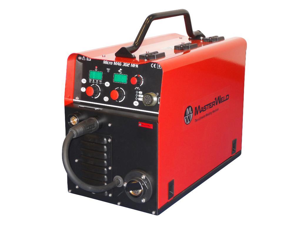
4 1 INTRODUCTION IMPORTANT! This handbook must be consigned to the user prior to installation and commissioning of the unit. Read the "General prescriptions for use" handbook supplied separately from this handbook before installing and commissioning the unit. The meaning of the symbols in this manual and the associated precautionary information are given in the "General prescriptions for use. If the "General prescriptions for use" are not present, it is mandatory to request a replacement copy from the manufacturer or from your dealer. Retain these documents for future consultation. KEY DANGER! This pictogram warns of danger of death or serious injury. WARNING! This pictogram warns of a risk of injury or damage to property. CAUTION! This pictogram warns of a potentially hazardous situation. INFORMATION This pictogram gives important information concerning the execution of the relevant operations. INTRODUCTION is a compact and rugged three-phase, synergic inverter power source for MIG/MAG, MMA and TIG Lift welding. Easy to transport, only 22 kg, it is the best option for maintenance and repair on field, shipyard and off -shore operations. Polarity change allows welding with self shielded wires. Innovative unique MAC (Masterweld Arc Control) supplies a soft and very stable MIG/MAG arc with excellent weld bead quality and minimal spattering in any working conditions. 3T Mode allows both Hot Start and Crater Filler current setting, for optimal penetration at start and crater filling at bead s end. Additional parameters, Motor Slope, Soft Start, Burn Back and Post Gas are included for perfect arc ignition and optimum wire cutting at the end of welding. Microprocessor, inverter technology, digital displays, synergic curves and memory locations for customized welding parameters assure complete welding process repeatability. The inductance can be adjusted electronically by means of the user interface in order to optimize the arc. Perfect wire feeding is guaranteed thanks to a 4-rolls motor drive included in. Fan. The fan is turned on only during welding, at the end of the welding process it remains on for a fixed period of time according to welding conditions. The fan is nonetheless controlled by specific thermal sensors that guarantee a correct cooling of the machine. Accessories that can be connected to the unit: - Manual remote controller for remote adjustment of the welding current. - Push-Pull torch (purchasing and installing the relative kit). This symbol identifies an action that occurs automatically as a result of a previous action. This symbol identifies additional information or a reference to a different section of the manual containing the associated information. This symbol identifies a reference to a chapter of the manual. NOTES The figures in this manual are purely guideline and the images may contain differences with respect to the actual equipment to which they refer. 4/34
5 Cod INSTALLATION DANGER! Lifting and positioning Read the warnings highlighted by the following symbols in the General prescriptions for use. 2.3 REAR PANEL CONNECTIONS TO THE ELECTRICAL MAINS NETWORK The characteristics of the mains power supply to which the equipment shall be connected are given in the section entitled Technical data on page 24. The machine can be connected to engine generators provided their voltage is stabilised. Connect/disconnect the various devices with the machine switched off. 2.2 FRONT PANEL Wire feed motor power transformer fuse. Type: Delayed acting (T) Amperage: 630 ma Voltage: 500 V 2. Welding power source ON/OFF switch. 3. Mains protection ON LED. 4. Connector for gas feed hose: cylinder power source 5. Power cable. Total length (including internal part): 3,5 m Number and cross section of wires: 4 x 2,5 mm 2 Power plug type: not supplied Remote controller connector. 2. Negative pole welding socket. 3. Positive pole welding socket. 4. Polarity selector cable. 5. EURO TORCH welding socket. 5/34
6 2.4 PREPARING FOR MMA WELDING Preparing for MMA (polarity to basic electrode) 1. Set the welding power source ON/OFF switch to O (unit deenergized). 2. Plug the power cable plug into a mains socket outlet. 3. Choose the electrode based on the type of material and thickness of the workpiece to be welded. 4. Insert the electrode in the electrode holder. 5. Connect the electrode holder cable to the welding socket based on the polarity requested by the type of electrode used. 6. Connect the plug of the ground clamp to the welding socket on the basis of the polarity required. 7. Connect the earth clamp to the workpiece being processed. DANGER! Electric shock hazard! Read the warnings highlighted by the following symbols in the General prescriptions for use. 8. Set the welding power source ON/OFF switch to I (unit powered). 9. Select the following welding mode on the selector located in the spool compartment: MMA 10. Set the required welding parameter values on the user interface. When the remote controller [RC] is connected and the relative locking screw is tightened, welding current can be adjusted using the remote controller. The system is ready to start welding. 6/34
7 2.5 PREPARING FOR TIG WELDING Preparing for TIG (polarity for tungsten electrode) Cod Set the welding power source ON/OFF switch to O (unit deenergized). 2. Plug the power cable plug into a mains socket outlet. 3. Connect the gas hose from the welding gas cylinder to the rear gas socket. 4. Open the cylinder gas valve. 5. Connect the TIG torch plug to the EURO TORCH welding socket. 6. Choose the electrode based on the type of material and thickness of the workpiece to be welded. 7. Insert the electrode in the TIG torch. 8. Connect the plug of the polarity selector cable to the welding socket on the basis of the polarity required. 9. Connect the plug of the ground clamp to the welding socket on the basis of the polarity required. 10. Connect the earth clamp to the workpiece being processed. 11. Set the welding power source ON/OFF switch to I (unit powered). 12. Select the following welding mode on the selector located in the spool compartment: DC TIG 13. Open the gas solenoid valve by pressing and releasing the button. 14. Use the flow control valve to adjust the flow of gas as required while the gas is flowing out. 15. Close the gas solenoid valve by pressing and releasing the button. 16. Set the required welding parameter values on the user interface. When the remote control pedal is connected and the relative locking screw is tightened the welding current will vary in relation to the pressure exerted on the pedal. The system is ready to start welding. 7/34


8 2.6 PREPARING FOR MIG/MAG WELDING WIRE SPOOL POSITIONING 1. Open the unit side door to gain access to the spool compartment. 2. Unscrew the cap of the spool holder POSITIONING THE WIRE IN THE WIRE FEEDER 1. Lower the wire feeder pressure devices. 3. If necessary, fit an adapter for the wire spool. 2. Raise the wire feeder pressure arms. 3. Remove the protective cover. 4. Choose the wire on the basis of the workpiece thickness and material type. 5. Fit the spool in the spool holder, ensuring it is located correctly. 6. Adjust the spool holder braking system by tightening/loosening the screw in such a way that the wire feed force is not excessive and when the spool stops rotating no excess wire is released. 4. Check that the feed rolls are suitable for the wire gauge. (See 7.2 page 29.) The diameter of the roll groovemust be compatible with the diameter of the welding wire. The roll must be of suitable shape in relation to the composition of the wire material. The groove must feature a "U" profile for soft materials (Aluminium and its alloys, CuSi3). The groove must be "V" shaped for harder materials (SG2-SG3, stainless steels). Rolls with a knurled groove profile are available for flux-cored wire. 7. Refit the plug. 8/34


9 5. Feed the wire between the wire feeder rolls and insert it into the MIG/MAG TORCH connector plug. 6. Make sure the wire is located correctly in the roll grooves. 7. Close the wire feeder pressure arms. 8. Adjust the pressure system so that the arms press the wire with a force that does not deform it while also ensuring constant feed rate without slipping CONNECTIONS TO SOCKETS Cod Set the welding power source ON/OFF switch to O (unit deenergized). 2. Plug the power cable plug into a mains socket outlet. 3. Connect the gas hose from the welding gas cylinder to the relative socket. 4. Open the cylinder gas valve. 5. Connect the MIG/MAG torch plug to the EURO TORCH welding socket. 6. Connect the plug of the ground clamp to the welding socket on the basis of the polarity required. 7. Connect the plug of the polarity selector cable to the welding socket on the basis of the polarity required. 8. Connect the earth clamp to the workpiece being processed. 9. Set the welding power source ON/OFF switch to I (unit powered). 10. Select the following welding mode on the selector located in the spool compartment: MIG/MAG 9. Refit the protective cover. 10. Close the spool compartment door in the side of the unit. 11. Feed the wire through the torch until it protrudes from the tip, pressing button on the unit's user interface. The insertion speed is 1.2 m/min for 3 seconds, subsequently increasing to 10 m/min. When the button is released wire feed is interrupted. This function produces a slower feed rate and hence greater precision when inserting the wire when it enters the torch nozzle. 12. Select the torch trigger procedure on the user interface. 13. Open the gas solenoid valve by pressing and releasing the button. 14. Use the flow control valve to adjust the flow of gas as required while the gas is flowing out. 15. Close the gas solenoid valve by pressing and releasing the button. 16. Set the required welding parameter values on the user interface. On connecting and enabling a remote controller [RC] certain settings can be modified from said controller without having to take action on the user interface of the welding power source. The system is ready to start welding. 9/34
10 Preparing for MIG/MAG 10/34
11 Cod COMMISSIONING 3.1 USER INTERFACE CODE SYMBOL L1 L2 L3 L4 L5 L6 L7 L8 L9 L10 L11 L12 L13 L10 L11 L12 DESCRIPTION This LED illuminates to show an anomaly in the operating conditions. See 3.7 ALARMS MANAGEMENT page 16. Illumination of this LED indicates the display of the average voltage and current value measured during the final moments of welding. The value appears on the following displays: D1-D2 This LED illuminates to confirm the presence of power on the output sockets. Illuminates to show a value in the following unit of measurement: METRES PER MINUTE Illuminates to show a value in the following unit of measurement: AMPERES Illuminates to show a value in the following unit of measurement: MILLIMETRES Illuminates to show a value in the following unit of measurement: SECONDS Illuminates to show a value in the following unit of measurement: VOLTS Illuminates to show a value in the following unit of measurement: PERCENTAGE When this LED illuminates the following parameter can be set: WIRE FEED RATE When this LED illuminates the following parameter can be set: WELDING CURRENT When this LED illuminates the following parameter can be set: THICKNESS Illuminates to show that the required Synergic welding program can be set. Illumination shows that the following function has been activated: 2 stroke procedure. Illumination shows that the following function has been activated: 4 stroke procedure. Illumination shows that the following function has been activated: 3 stroke Special procedure. 11/34
12 CODE SYMBOL D1 D2 S1 S2 DESCRIPTION Parameters/functions setting Manual MIG/MAG mode: the display shows the programmed wire feed rate. Synergic MIG/MAG mode: the display shows the value of the selected main welding parameter. Welding MIG/MAG mode: The display shows the modification of the main welding parameter. MMA mode: The display shows the effective amperes value during welding. TIG Mode: The display shows the effective amperes value during welding. Menu function The display shows the acronym of the parameter or function to be adjusted. Programs setting The display shows the message P program no.. Parameters/functions setting Manual MIG/MAG mode: the display shows the programmed voltage. Synergic MIG/MAG mode: the display shows the arc correction value imposed by the operator with respect to the default value of the synergic curve. Welding MIG/MAG mode: The display shows the effective voltage value during welding. Menu function The display shows the value of the parameter or function to be adjusted. Programs setting The display shows the acronym of the material to be welded on the basis of the selected synergic curve. MIG/MAG mode: this button activates wire feed to insert it through the MIG/MAG torch. Parameters/functions setting Manual MIG/MAG mode: the button selects one of the following settings: WIRE FEED RATE - SYNERGIC PROGRAM Synergic MIG/MAG mode: the button selects one of the following settings: WIRE FEED RATE - WELDING CURRENT - THICKNESS - SYNERGIC PROGRAM In all welding modes This button provides the facility to gain access to the secondary parameters adjustment menu. Powering up the unit This button opens the initial setup menu. S3 S4 S5 E1 E2 This button opens the gas solenoid valve to fill the circuit and calibrate the pressure with the regulator on the gas cylinder. Gas menu function Hold down the button for 3 seconds to open the menu. Press and release: the button opens the JOBs upload menu. Hold down for 3 seconds: the button opens the JOBs save and delete menu. MIG/MAG mode: this button selects the torch trigger procedure. Parameters/functions setting Manual MIG/MAG mode: the encoder sets the wire feed rate. Synergic MIG/MAG mode: the encoder sets the main adjustment value. Welding The encoder selects the main welding parameter to be set. Menu function The encoder selects the function or parameter to be adjusted. Programs setting The encoder selects the synergic program to be uploaded. Parameters/functions setting Manual MIG/MAG mode: the encoder sets the welding voltage. Synergic MIG/MAG mode: the encoder sets the arc correction. Menu function The encoder sets the value of the selected function or parameter. Programs setting The encoder selects the MIG/MAG welding program. 12/34
13 Cod CODE SYMBOL POT1 SEL1 DESCRIPTION Manual MIG/MAG mode: the potentiometer sets the inductance value. Synergic MIG/MAG mode: the potentiometer sets the inductance value from the minimum to the maximum permissible value in accordance with the selected synergic curve. The selector sets the welding mode. 3.2 UNIT POWER-UP Set the welding power source ON/OFF switch to I to switch on the unit. F x.x The message appears for a few seconds on the following displays: D1-D2 x.x= software version. First power-up or power-ups following a RESET procedure The welding power source sets up for welding with the factory presets. Subsequent power-ups The welding power source sets up for welding in the latest stable welding configuration that was active at the time of power-off. 3.3 RESET (LOAD FACTORY SETTINGS) The reset procedure involves complete restoration of the default values, parameters and memory settings set in the factory. All memory locations will be reset and hence all your personal welding settings will be lost! The reset procedure is useful in the following cases: - Too many changes made to the welding parameters so user finds it difficult to restore defaults. - Unidentified software problems that prevent the welding power source from functioning correctly. Set the welding power source ON/OFF switch to O to switch the unit off. S3 S5 Hold down both buttons simultaneously. Set the welding power source ON/OFF switch to I to switch on the unit. SIMULTANEOUS ACTIONS rec FAC The message appears on the following displays: D1-D2 Wait for the memory clear procedure to terminate. 13/34
14 3.4 SET-UP (INITIAL SET-UP OF THE WELDING POWER SOURCE) Set the welding power source ON/OFF switch to O to switch the unit off. SEL1 Set the selector to the following welding mode: MIG/MAG S2 Hold down the button. Set the welding power source ON/OFF switch to I to switch on the unit. SIMULTANEOUS ACTIONS E1 E2 E1 S2 Set UP The message appears for a few seconds on the following displays: D1-D2 The acronym relative to the setting to be edited appears on the following displays: D1 The value relative to the selected setting appears on the following displays: D2 Using the encoder, select the setting to be changed. Using the encoder, edit the value of the selected setting. Use the encoder to select the following setting: ESC Press any button to save the setting and quit the menu. Tab. 1 - Setup settings ACRONYM SETTING MIN DEFAULT MAX rc REMOTE CONTROLLER SELECTION off off 6 LoC LOCK STATUS ACTIVATION off off 3 PP PUSH PULL ACTIVATION off (purchasing and installing the relative kit) off on bb. SELECTION OF BURN TYPE SPc Std Std ESC QUITTING THE MENU OFF OFF REMOTE CONTROLLER SELECTION OFF= No remote controller enabled. 3= The unit is enabled to receive commands from a remote control equipped with 1 potentiometer. 4= The unit is enabled to receive commands from a remote control equipped with 2 potentiometers. 5= The unit is enabled to receive commands from a remote control equipped with 1 UP/DOWN lever. 6= The unit is enabled to receive commands from a remote control equipped with 2 UP/DOWN levers. LOCK STATUS ACTIVATION OFF= All adjustments enabled = All adjustments are disabled with the exceptions shown in Tab. 2 page 15. SELECTION OF BURN TYPE SPc= The setting activates Special burning. Std= The setting activates Standard burning. QUITTING THE MENU To quit the menu select this setting and press button S2. 14/34
15 Cod LOCKING PROCEDURE The locks are enabled only in MIG/MAG welding mode. The procedure inhibits unit adjustments, allowing the user to modify only certain settings depending on the selected lock status. The procedure is used to prevent accidental alteration of the unit settings and welding settings by the operator. Enabling If no locking status is selected (LOC = off) and if you wish to set up a limitation on use of the power source, display the LOC function in the SETUP menu. Open the Setup menu. The acronym relative to the setting to be edited appears on the following displays: D1 The value relative to the selected setting appears on the following displays: D2 E1 Use the encoder to select the following setting: LoC E2 Use the encoder to select the required lock status. Depending on the selected Lock, certain functions will remain enabled. E1 Use the encoder to select the following setting: ESC S2 Press any button to save the setting and quit the menu. Tab. 2 - Functions not disabled by Locks LOCK STATUS USER INTERFACE RC03 RC04 RC05 RC06 OFF All adjustments enabled. All adjustments enabled. All adjustments enabled. All adjustments enabled. All adjustments enabled. Selection of torch trigger procedure (button S5) 1 Display of main welding parameters (button S2) Arc correction Arc correction (UP/DOWN Arc correction (encoder E2) (Potentiometer Pot2) lever 2) Wire insertion (button S1) Gas test (button S3) 2 Selection of torch trigger procedure (button S5) Display of main welding parameters (button S2) Arc correction (encoder E2) Synergy (encoder E1) Wire insertion (button S1) All adjustments enabled. All adjustments enabled. All adjustments enabled. All adjustments enabled. 3 (*1) Gas test (button S3) Selection of torch trigger procedure (button S5) Display of main welding parameters (button S2) JOB selection (encoder E2) Wire insertion (button S1) Gas test (button S3) Disabling If a lock status is selected, you can only edit parameters permitted by the currently active lock status. Open the Setup menu. The acronym relative to the setting to be edited appears on the following displays: D1 The value relative to the selected setting appears on the following displays: D2 E1 Use the encoder to select the following setting: LoC E2 Use the encoder to select the following setting: off E1 Use the encoder to select the following setting: ESC S2 Press any button to save the setting and quit the menu. 3.6 GAS FLOW ADJUSTMENT When the unit is powered on the solenoid valve opens for 1 second. This serves to fill the gas circuit. Scroll JOBS (UP/DOWN lever 1) Scroll JOBS (UP/DOWN lever 1) S3 S3 Open the gas solenoid valve by pressing and releasing the button. Adjust the pressure of gas flowing from the torch by means of the flow meter connected to the gas cylinder. Close the gas solenoid valve by pressing and releasing the button. The solenoid valve closes automatically after 30 seconds. 15/34
16 3.7 ALARMS MANAGEMENT This LED illuminates if an incorrect operating condition occurs. An alarm message appears on the following display: D3 Tab. 3 - Alarm messages MESSAGE MEANING EVENT CHECKS AL. HEA. Overheating alarm Indicates tripping of the welding power source thermal protection. All functions disabled. Exceptions: - cooling fan. Leave the unit running so that the overheated components cool as rapidly as possible. When the unit has cooled, the welding power source will reset automatically. All functions disabled. Exceptions: - cooling fan. An audible signal will sound (buzzer). - Make sure that the power required by the welding process is lower than the maximum rated power output. - Check that the operating conditions are in compliance with the welding power source data plate specifications. - Check for the presence of adequate air circulation around the welding power source. AL. Cur. Overcurrent alarm Indicates tripping of the welding power source current surge protection. Muting the audible signal: - in torch trigger procedure 2T, release the torch trigger. - In torch trigger procedure 4T or 3TS the alarm mutes automatically after 5 seconds. - Check that the programmed arc voltage value is not too high in relation to the thickness of the work to be welded. Exit the alarm state by performing one of the following actions: - press any button. - switch the power source off. 16/34
17 Cod WELDING SETTINGS 4.1 TORCH TRIGGER MODES 2 STROKE LIFT-ARC TIG WELDING (2T) 1. Touch the workpiece with the torch electrode. 2. Press (1T) and keep the torch trigger pressed. 3. Slowly lift the torch to strike the arc. The welding current reaches the preset value, by way of a up slope time, if programmed. 4. Release (2T) the trigger to start the weld completion procedure. The current reaches the end current value in the time set in the down slope time parameter. The arc is extinguished. Gas delivery continues for the time set in the post gas parameter. 4 STROKE LIFT-ARC TIG WELDING (4T) 1. Touch the workpiece with the torch electrode. 2. Press (1T) and release (2T) the torch trigger. 3. Slowly lift the torch to strike the arc. The welding current reaches the preset value, by way of a up slope time, if programmed. 4. Press (3T) the trigger and keep it pressed to start the weld completion procedure. The current reaches the end current value in the time set in the down slope time parameter. The arc continues and the current output will be the value set in the end current parameter. In these conditions the weld pool can be closed (crater filler current). 5. Release (4T) the trigger to extinguish the arc. Gas delivery continues for the time set in the post gas parameter. 2 STROKE MIG/MAG WELDING (2T) 1. Bring the torch up to the workpiece. 2. Press (1T) and keep the torch trigger pressed. The wire advances at the approach speed until making contact with the work. The arc strikes and the wire feeder accelerates to the set feed rate value. 3. Release (2T) the trigger to start the weld completion procedure. Gas flow continues for the time set in the post gas parameter (adjustable time). 4 STROKE MIG/MAG WELDING (4T) 1. Bring the torch up to the workpiece. 2. Press (1T) and release (2T) the torch trigger. The wire advances at the approach speed until making contact with the work. The arc strikes and the wire feeder accelerates to the set feed rate value. 3. Press (3T) the trigger to start the weld completion procedure. Gas flow continues until the torch trigger is released. 4. Release (4T) the torch trigger to start the post gas procedure (adjustable time). 3 STROKE SPECIAL MIG/MAG WELDING (3TS) 1. Bring the torch up to the workpiece. 2. Press (1T) the torch trigger. The wire advances at the approach speed until making contact with the work. The welding arc strikes and the wire feed rate changes to the first welding level (hot start), which is set as a percentage of the normal welding feed rate. This first level is used to create the weld pool: for example, when welding aluminium a value of 130 % is recommended. 3. Release (2T) the trigger to switch to normal welding speed; the switch to normal welding speed is performed in accordance with the start ramp, which can be set in seconds. 4. Press the torch trigger again (Level 3) to switch to the third welding level (crater filler), which is set as a percentage of the normal welding feed rate. The switch of welding current level in terms of crater filling is performed in accordance with the crater ramp, which can be set in seconds. This third level is used to complete the weld and fill the final crater (crater filler) in the weld pool: for example, when welding aluminium a value of 80 % is recommended. 5. Release the torch trigger a second time (4T) to close the weld and run the post gas procedure. 17/34
18 4.2 SELECTION OF THE WELDING MODE AND TORCH TRIGGER PROCEDURE Specific torch trigger procedures are available in accordance with the selecting welding mode. The availability of certain procedures depends on whether or not certain parameters or functions of the unit are enabled or set in the associated menus. The table shows the settings to be made to enable each procedure. KEY 2T: 2 STROKE 4T: 4 STROKE 3TS: 3 STROKE SPECIAL 1: Not enabled with manual program P0. : Always available. SEL1 Use this selector to select one of the following welding modes. S5 Use this button to select one of the following torch trigger procedures. PROCEDURE MODE 2T 4T 3TS MMA TIG DC CONTINUOUS MIG/MAG PARAMETERS ACTIVATION The welding parameters are available in accordance with the selected welding mode and procedure. The table shows the settings required to enable each parameter. KEY 1: Not enabled with manual program P0. : Always available. MENU MODE PROCEDURE PARAMETER 1 WELDING CURRENT ARC CORRECTION 1 INDUCTANCE 1 WIRE FEED RATE 1 THICKNESS PROGRAMS 2 HOT-START 2 ARC FORCE 2 CRATER FILLER 2 3 LEVELS SLOPE 2 SOFT START 2 MOTOR SLOPE 2 BURN BACK GAS POST GAS TIME GAS PRE-GAS TIME 18/34
19 4.4 WELDING PARAMETERS WELDING CURRENT Output current value during welding. HOT-START (MMA) This parameter aids electrode melting at the time of arc striking. Consequences of a higher value: - Easier arc strike. - Increased spatter at welding start. - Increase of strike area. Consequences of a lower value: - More difficult arc strike. - Less spatter at welding start. - Smaller strike area. HOT-START (MIG/MAG) This function is useful when using aluminium alloy welding wire. Consequences of a higher value: - Greater heat output. - Greater penetration. Consequences of a lower value: - "Cold" weld bead. ARC FORCE This parameter helps to avoid electrode sticking during welding. During electrode fusion low conductivity parts of the coating become detached and tend to become interposed between the electrode tip as it is fusing and the workpiece. This condition results in an interruption of the arc. In addition, it may occur that the electrode comes into contact with the workpiece creating a short circuit and consequent quenching of the arc. To avoid arc quenching the power source therefore delivers instantaneous peak currents in correspondence with preset arc voltage thresholds. Consequences of a higher value: - Fluidity during welding. - Welding arc stability. - Greater electrode fusion in workpiece. - More welding spatter. Consequences of a lower value: - The arc is extinguished more easily. - Less welding spatter. MOTOR SLOPE Time required to switch from SOFT START speed to welding speed. ARC CORRECTION IN VOLTS This parameter corrects the synergic voltage value relative to the synergic point of the MIG/MAG processes. The default value for horizontal and frontal welding is 0.0 V. NOTE: A value >0 produces an increase in the length of the welding arc, while a value <0 produces a shorter arc. INDUCTANCE Consequences of a higher value: - "Softer welding". - Less spatter. - Less positive starting. Consequences of a lower value: - "Harder welding". - More spatter. - More reliable starting. Cod CAUTION: an excessively long value will slow the welding procedure. Other than in the presence of special requirements the value should generally be kept at 0.0 s or anyway very low. Consequences of a higher value: - This parameter allows a shielded environment to be created, thereby eliminating contaminants at the start of the welding pass. SOFT START The soft start is the wire approach speed to the workpiece. The value is expressed as a percentage of the set feed rate. Consequences of a lower value: - The start of welding is "softer". Consequences of a higher value: - The welding start may prove difficult. BURN BACK The burn back value is associated with the quantity of wire that is burnt at the end of the welding procedure. Consequences of a higher value: - Wire significantly retracted into the torch nozzle. Consequences of a lower value: - Stick-out at welding start is longer. POST GAS Time of post gas delivery when the welding arc is extinguished. This is useful when welding at high current values or with materials that oxidise readily to cool the weld pool in an uncontaminated atmosphere. In the absence of specific requirements the value should generally be kept low. Consequences of a higher value: - More effective pickling (improved appearance of workpiece at the end of the welding pass). - Higher gas consumption. Consequences of a lower value: - Lower gas consumption. - Oxidation of electrode tip (more difficult arc strike). CRATER FILLER This parameter serves to obtain a uniform deposit at the end of the welding process to fill the crater with a reduced wire feed rate to facilitate the deposition of filler material. By keeping the torch trigger pressed during the 3rd time, the wire feed rate is reduced (crater filler speed) thereby ensuring optimal crater filling, until the POST GAS time is started by releasing the torch trigger (4Th time). Consequences of a higher value: - Difficult crater filling (values greater than 100%). Consequences of a lower value: - Cold welding (values close to 1%). 3 LEVELS SLOPE Establishes the duration of the slope between the 1st and 2nd time and between the 3rd and 4th time. PRE GAS Time of gas delivery before the arc strike. 19/34
20 5 WELDING SETTINGS 5.1 ELECTRODE WELDING (MMA) SEL1 Select the following welding mode on the selector located in the spool compartment: MMA MMA The message appears on the following displays: D PARAMETERS SETTING E1 Using the encoder, edit the value of the parameter. The value appears on the following display: D1 The value is saved automatically PARAMETERS SETTING: (1ST LEVEL) S2 E1 E2 Tab. 4 - Main welding parameters: MMA mode PARAMETER MIN DEFAULT MAX WELDING CURRENT 10 A 80 A 250 A Hold down the button for 3 seconds to gain access to the 1st level menu. The acronym relative to the setting to be edited appears on the following displays: D1 The value relative to the selected setting appears on the following displays: D2 Use the encoder to scroll the list of settings to edit. Using the encoder, edit the value of the selected setting. Press any button to save the setting and quit the menu. 5.2 DC TIG WELDING SEL1 Tab. 5 - Parameters of the 1st level menu: MMA mode ACRONYM PARAMETER MIN DEFAULT MAX H.S. HOT-START 0 % 50 % 100 % A.F. ARC FORCE 0 % 30 % 100 % Select the following welding mode on the selector located in the spool compartment: DC TIG tig The message appears on the following displays: D PARAMETERS SETTING E1 Using the encoder, edit the value of the parameter. The value appears on the following display: D1 The value is saved automatically PARAMETERS SETTING: (GAS MENU) S3 E2 Tab. 6 - Main welding parameters: DC TIG mode PARAMETER MIN DEFAULT MAX WELDING CURRENT 10 A 80 A 250 A Hold down the button for 3 seconds to open the menu. The acronym relative to the setting to be edited appears on the following displays: D1 The value relative to the selected setting appears on the following displays: D2 Using the encoder, edit the value of the selected setting. Press any button to save the setting and quit the menu. Tab. 7 - GAS menu parameters: DC TIG mode ACRONYM PARAMETER MIN DEFAULT MAX Po.G. POST GAS TIME 0.0 s 3.0 s 10.0 s *1 *1: When a synergic program is loaded the default value of the parameter is defined automatically by the software and the message "SYN" will be shown on the display. 20/34
21 Cod MIG/MAG WELDING SEL1 Select the following welding mode on the selector located in the spool compartment: MIG/MAG PARAMETERS SETTING ARC CORRECTION E2 Using the encoder, edit the value of the parameter. The value is saved automatically. INDUCTANCE SETTING POT1 Using the potentiometer, edit the value of the parameter. PARAMETER MIN DEFAULT MAX ARC CORRECTION 10.0 V V PARAMETERS SETTING: (1ST LEVEL) S2 E1 Press this button to scroll the list of settings to edit. The LED associated with the selected setting will illuminate. The value relative to the selected setting appears on the following displays: D1 Using the encoder, edit the value of the selected setting. The value is saved automatically. Tab. 8 - Parameters of the 1st level menu: MIG/MAG mode PARAMETER MIN DEFAULT MAX WIRE FEED RATE 1.0 m/min 20.0 m/min *1 WELDING CURRENT - Syn - *1 THICKNESS - Syn - *1 *2 PROGRAMS P0 P0 P34 *1 Tab. 9 - Programmed synergic curves Syn: By synergy we mean a simple and fast way to regulate the generator. Through this function, an optimum balancing of all the welding parameters in every position can be granted, thus helping the user. This is the reason why the synergic curves of most of the wire types have been introduced, however these curves can be easily modified so as to allow the user to optimise his own welding procedure. NOTE: The synergic curves were created with reference to a fillet weld in position PB (horizontal-vertical) with 10 mm stick-out (distance from torch to workpiece). P R O G R A M M I WIRE DIAMETER ACRONYM WIRE MATERIAL (GAS MIXTURE) P0 P0 P0 P0 MAn MANUAL P1 P2 P3 --- FE SG2/SG3 (80 % Ar - 20 % CO2) P4 P5 P6 --- FE SG2/SG3 (92 % Ar - 8 % CO2) P7 P8 P9 --- FE SG2/SG3 (100 % CO2) P10 P11 P S.S. INOX 308 (98 % Ar - 2 % CO2) P13 P14 P S.S. INOX 316 (98 % Ar - 2 % CO2) P16 P17 P AL AlMg5 (100 % Ar) P19 P20 P AL AlSi5 (100 % Ar) P22 P23 P CU.S. CuSi3 (100 % Ar) P25 P26 P CU.A. CuAl8 (100 % Ar) P28 P29 rfc RFCW (80 % Ar - 20 % CO2) P30 P31 bfc BFCW (80 % Ar - 20 % CO2) P32 P33 MFC MFCW (80 % Ar - 20 % CO2) P npr FREE PROGRAMS *1: By changing the main adjustment value shown on display D1, the voltage value of the synergic curve shown on display D2 changes accordingly. *2: Reference is made to "T" fillet welds on identical thicknesses. The relative value is purely guideline. 21/34
22 5.3.3 PARAMETERS SETTING: (2ND LEVEL) S2 E1 E2 Hold down the button for 3 seconds to gain access to the 2nd level menu. The acronym relative to the setting to be edited appears on the following displays: D1 The value relative to the selected setting appears on the following displays: D2 Use the encoder to scroll the list of settings to edit. Using the encoder, edit the value of the selected setting. Press any button to save the setting and quit the menu. Tab Parameters of the 2nd level menu: MIG/MAG mode ACRONYM PARAMETER MIN DEFAULT MAX H.-S. HOT-START 1 % 130 % 200 % C.-F. CRATER-FILLER 1 % 80 % 200 % S.3L. 3 LEVELS SLOPE 0.1 s 0.5 s 10.0 s S.-S. SOFT-START 10 % 30 % 100 % *1 SLO. MOTOR SLOPE 0.0 ms 40 ms 200 ms *1 b.-b. BOURN BACK 0.0 ms 26 ms 100 ms * PARAMETERS SETTING: (GAS MENU) S3 E1 E2 Hold down the button for 3 seconds to open the menu. The acronym relative to the setting to be edited appears on the following displays: D1 The value relative to the selected setting appears on the following displays: D2 Use the encoder to scroll the list of settings to edit. Using the encoder, edit the value of the selected setting. Press any button to save the setting and quit the menu. Tab GAS menu parameters: MIG/MAG mode ACRONYM PARAMETER MIN DEFAULT MAX Po.G. POST GAS TIME 0.0 s 0.3 s 10.0 s *1 P.G. PRE-GAS TIME 0.0 s 0.0 s 10.0 s *1 *1: When a synergic program is loaded the default value of the parameter is defined automatically by the software and the message "SYN" will be shown on the display. 22/34
23 Cod JOBS MANAGEMENT Personalised welding settings, or JOBs, can be saved in memory locations and subsequently uploaded. Up to 50 JOBS can be saved (j01-j50). The settings of the SETUP menu are not saved. JOBs can be managed only when the unit is not in welding mode SAVING A JOB S4 E2 Hold down the button for 3 seconds. S.A. J.xx The message appears on the following displays: D1-D2 xx= number of the first free JOB. Use the encoder to select the required JOB number. On selecting a currently occupied memory location, the JOB number flashes. If you confirm at this point, the new JOB will overwrite the previously saved settings. Exit without confirmation Press any button (except S4). This action will automatically close the menu. Exit with confirmation S4 Press the button. This action will automatically close the menu LOADING A USER JOB S4 Press and release the button. LO. J.xx Only when the JOBs have been uploaded, the message is shown on the following displays: D1-D2 xx= number of the latest JOB used. no. Job If there are no JOBs in the memory the message is shown on the following displays: D1-D2 E2 Using the encoder, select the JOB number to load. Exit without confirmation Press any button (except S4). This action will automatically close the menu. Exit with confirmation S4 Press the button. This action will automatically close the menu. J. xx The loaded JOB number is shown on the following display: D2 xx= number of loaded JOB DELETING A JOB S4 Hold down the button for 3 seconds. S.A. J.xx The message appears on the following displays: D1-D2 xx= number of the first free JOB. E1 Use the encoder to select the following setting: Er. E2 Use the encoder to select the number of the JOB to be deleted. Exit without confirmation Press any button (except S4). This action will automatically close the menu. Exit with confirmation S4 Press the button. This action will automatically close the menu. 23/34
24 6 TECHNICAL DATA Directives applied Construction standards Conformity markings Supply voltage Mains protection Zmax Dimensions ( L x D x H ) Weight Insulation class Protection rating Cooling Maximum gas pressure Motor speed Wire spool: (dimensions/weight) Static characteristic Current and voltage adjustment range Welding current / Working voltage Maximum input power Maximum supply current 2002/96/EC-Waste electrical and electronic equipment (WEEE) 2004/108/EC-Electromagnetic compatibility (EMC) 2006/95/EC-Low voltage (LVD) 2011/65/EU-Restriction of the use of certain hazardous substances (RoHS) EN ; EN ; EN Class A Equipment compliant with European directives in force Equipment suitable in an environment with increased hazard of electric shock Equipment compliant with directive 2002/96/EC-(WEEE) Equipment compliant with directive 2011/65/EU-(RoHS) 3 x 400 Va.c. ± 15 % / Hz 16 A Delayed If this equipment is connected to a public low voltage system, it is the responsibility of the installer or user of the equipment to ensure, by consultation with the distribution network operator if necessary, that the equipment may be connected. 560 x 280 x 390 mm 21.0 kg H IP23S AF: Air-over cooling (fan assisted) 0,5 MPa (5 bar) m/min 300 mm / 15 kg MMA Drooping characteristic TIG Drooping characteristic MIG/MAG Flat characteristic MMA 10 A / 20.4V A V TIG 10 A / 10.4 V A V MIG/MAG 5 A / 14.2 V A V 40 % (40 C) 250 A V MMA 60 % (40 C) 220 A V 100 % (40 C) 190 A V 50 % (40 C) 250 A V TIG 60 % (40 C) 240 A V 100 % (40 C) 210 A V 35 % (40 C) 300 A V MIG/MAG 60 % (40 C) 230 A V 100 % (40 C) 200 A V 40 % (40 C) 8.7 kva kw MMA 60 % (40 C) 7.3 kva kw 100 % (40 C) 6.1 kva kw 50 % (40 C) 6.1 kva kw TIG 60 % (40 C) 5.8 kva kw 100 % (40 C) 4.8 kva kw 35 % (40 C) 10.3 kva kw MIG/MAG 60 % (40 C) 6.9 kva kw 100 % (40 C) 5.8 kva kw 40 % (40 C) 12.7 A MMA 60 % (40 C) 10.6 A 100 % (40 C) 8.8 A 50 % (40 C) 8.8 A TIG 60 % (40 C) 8.3 A 100 % (40 C) 6.8 A 35 % (40 C) 15.0 A MIG/MAG 60 % (40 C) 10.0 A 100 % (40 C) 8.4 A 24/34
25 Cod Maximum effective supply current No-load voltage (U0) 40 % (40 C) 8.0 A MMA 60 % (40 C) 8.2 A 100 % (40 C) 8.8 A 50 % (40 C) 6.2 A TIG 60 % (40 C) 6.4 A 100 % (40 C) 6.8 A 35 % (40 C) 8.8 A MIG/MAG 60 % (40 C) 7.7 A 100 % (40 C) 8.4 A MMA 53 V TIG 53 V MIG/MAG 53 V 25/34
26 7 SPARE PARTS 26/34
27 N CODE DESCRIPTION KNOB CAP KNOB CAP KNOB + CAP KNOB WITH INDEX + CAP CABLE + REMOTE CONTROL CONNECTOR FRONT PANEL + LOGIC BOARD POLARITY SELECTOR CABLE BLIND METAL FRONT PLATE COMPLETE FIXED SOCKET PLASTIC HOUSING FRONT PLATE CAPILLARY TUBE FOR EURO CONNECTOR AXIAL EURO BODY CURRENT CLAMP FOR BRASS GUIDE BRASS GUIDE FOR EURO CONNECTOR MOTOR SUPPORT PLATE LOGIC PROTECTION PLATE CAP Ø= SWITCH + CABLE PLATE SLIDE CLOSURE RUBBER FOOT LOWER COVER DOOR PLATE WIRE FEED MOTOR SPOOL SUPPORT INTERNAL PLATE PLASTIC HINGE REAR PLATE BLIND METAL REAR PLATE SOLENOID VALVE RED LED CABLE NEOPRENE CABLE FUSE HOLDER SOLENOID VALVE BLOCK PLATE THREE-POLE SWITCH COMPLETE CABLE CLAMP HANDLE TUBE SUPPORT PLATE PIN HANDLE TUBE REAR FIXING PLATE THREE-PHASE POWER INPUT PROTECTION BOARD AUXILIARY TRANSFORMER PRIMARY CAPACITOR BOARD FAN CONTROL BOARD THERMAL CUT-OUT 75 C THREE PHASE BRIDGE RECTIFIER FAN FANS SUPPORT PLATE TRANSFORMER SUPPORT PLATE POWER TRANSFORMER DEFLECTOR PLATE POWER BOARD INTERNAL FRAMEWORKS THERMAL CUT-OUT 85 C COVER PLATE SNUBBER BOARD HALL-SOCKET COPPER BRACKET HALL EFFECT SENSOR Cod DIODES-HALL COPPER BRACKET DIODES-TRANSFORMER COPPER BRACKET ISOTOP DIODE INDUCTANCE OBLIQUE PLATE FOR DEFLECTOR INTERNAL DEFLECTOR PLATE HEAT SINK HEAT SINK MOTOR BOARD INTERNAL PLATE SCREW CAP FOR SPOOL SUPPORT N CODE DESCRIPTION TORCH CONNECTORS COMPLETE KIT SLEEVE HOSE ADAPTER FOR RUBBER HOSE HOSE CLAMP Ø= NUT 1/ CAPILLARY TUBE 27/34
28 7.1 WIRE FEED MOTOR 28/34
29 Cod N CODE DESCRIPTION COMPLETE PRESSURE ARM COMPLETE PRESSURE DEVICE MOTOR COIL INLET GUIDE WITH SOFT LINER FEED PLATE GUARD SAFETY KIT INSULATION MOUNTING KIT GEAR ADAPTOR FEED ROLL MAIN GEAR DRIVE SCREW SCREW GEAR ADAPTOR FEED ROLL SHAFT FEED ROLL WASHER PRESSURE ARM HOLDER AXIS SCREW SPRING PRESSURE ARM AUTO LIFT SPACE TUBE PRESSURE ARM AUTO-LIFT SCREW CIRCLIP LOCATING PIN PRESSURE ARM HOLDER AXLE GAUGE PRESSURE ROLL LOCATING PIN PRESSURE DEVICE GEAR ADAPTOR DRIVING FEED ROOL 7.2 WIRE FEEDER ROLLS D = 30 mm d = 14 mm N CODE WIRE DIAMETER GROOVE TYPE V groove Solid wire VK shape Flux-cored wire U shape Aluminium wire /34
30 8 ELECTRICAL DIAGRAM 8.1 MICRO MAG 302 MFK 30/34
31 Cod /34
32 8.2 REMOTE CONTROLLER RC03: ELECTRICAL DIAGRAM Pin Name Voltage Input/Output A +5 V 5 Vd.c. Out B AN2 (5 V) 0-5 Va.c. In C AN1 (5 V) 0-5 Va.c. In D GND GND Out E D1-IN 0-5 Vd.c. In F AN2 (10 V) 0-10 Va.c. In G D3-OUT 0-5 Vd.c. Out H AN1 (10 V) 0-10 Va.c. In I D2-IN 0-5 Vd.c. In J RC - Not used K - - Not used L - - Not used M - - Not used N - - Not used 10 kohm-100 kohm potentiometer RC04: ELECTRICAL DIAGRAM 10 kohm-100 kohm potentiometer 32/34
33 Cod RC05: ELECTRICAL DIAGRAM RC06: ELECTRICAL DIAGRAM 33/34
34 34/34
1 PRECAUTIONS AJ Button Selecting the operating mode. 2 START-UP (Fig. 1)
") INSTRUCTION MANUAL FOR CONTROL PANEL INTRODUCTION The panels DIGIBOX MIG P1 Art. 223 and DIGIBOX MIG P2 Art. 221 are designed to be connected to the wire feeder WF4/P. Below, DIGIBOX MIG P1 and DIGIBOX
INSTRUCTION MANUAL FOR CONTROL PANEL INTRODUCTION The panels DIGIBOX MIG P1 Art. 223 and DIGIBOX MIG P2 Art. 221 are designed to be connected to the wire feeder WF4/P. Below, DIGIBOX MIG P1 and DIGIBOX
INSTRUCTION MANUAL COMMANDER BDH MIG
 INSTRUCTION MANUAL COMMANDER BDH MIG Valid from 0327 50173001A Version 1.0 CONTENTS INTRODUCTION... 0-1 1. PRIMARY OPERATIONAL FUNCTIONS... 1-1 Reading and setting... 1-1 Programmes... 1-2 Trigger function...
INSTRUCTION MANUAL FOR WIRE WELDING MACHINE
 INSTRUCTION MANUAL FOR WIRE WELDING MACHINE IMPORTANT: BEFORE STARTING THE EQUIPMENT, READ THE CONTENTS OF THIS MANUAL, WHICH MUST BE STORED IN A PLACE FAMILIAR TO ALL USERS FOR THE ENTIRE OPERATIVE LIFE-SPAN
Kingstar MIG/MAG. Kingstar 400 TS Kingstar 520 TS KINGSTAR MIG
 Kingstar MIG/MAG Kingstar 400 TS Kingstar 520 TS KINGSTAR MIG 13 Kingstar MIG/MAG - art. 372 Kingstar 400 TS Three phase input 400V - 50/60 Hz +15% / -20% Fuse rating (slow blow) 20 A Input power Min.-max.
VarioSynergic 3400 / 4000 / 5000 VarioSynergic / / MIG/MAG welding PERFECT WELDING
 VarioSynergic 3400 / 4000 / 5000 VarioSynergic 3400-2 / 4000-2 / 5000-2 MIG/MAG welding PERFECT WELDING A high-calibre machine that s user-friendly, too. GENERAL REMARKS UTILISATION It s got the lot The
SHARP Plasma inverter cutting range
 SHARP Plasma inverter cutting range Sword edge cutting www.cemont.com The plasma expert advanced powerful all metals performance portable solutions plasma gouging maintenance high quality The plasma process
PEGAS 160 T PULSE HF PEGAS 200 T PULSE HF
 - 1 - WELDING INVERTER PEGAS 160 T PULSE HF PEGAS 200 T PULSE HF OPERATING MANUAL PEGAS 160-200 T PULSE manual EN 06 -2- CONTENT: 1. INTRODUCTION... 3 2. SAFETY INSTRUCTIONS AND WARNINGS... 4 3. TECHNICAL
PRESTOJET Plasma inverter cutting range
 PRESTOJET Plasma inverter cutting range Sword edge cutting www.saf-fro.com The plasma expert advanced powerful all metals performance portable solutions inverter plasma gouging maintenance high quality
AristoMig U320w 208/230/400/460/475/500 V 3~ 50/60 Hz With cooling unit and central connection
 Spare parts list Edition 060727 Valid for serial no. 310 -xxx -xxx, 445 -xxx -xxx, 620 -xxx -xxx The AristoMig 450 power source is renamed: New name Old name Mig 4500i AristoMig 450 Mig U4500i AristoMig
KEMPPI K5 WELDING EQUIPMENT. Kempact Pulse 3000 QUALITY, SPEED AND PRODUCTIVITY
 KEMPPI K5 WELDING EQUIPMENT Kempact Pulse 3000 QUALITY, SPEED AND PRODUCTIVITY 7.06.2018 Kempact Pulse 3000 POWERFUL MIG/MAG WELDER WITH GREAT CAPACITY Kempact Pulse 3000 is a great combination of power,
CITOCUT Plasma inverter cutting range
 CITOCUT Plasma inverter cutting range Sword edge cutting www.oerlikon-welding.com The plasma expert advanced powerful all metals performance portable solutions inverter plasma gouging maintenance high
CITOCUT Plasma inverter cutting range
 CITOCUT Plasma inverter cutting range Sword edge cutting www.oerlikon-welding.com The plasma expert advanced plasma cutting powerful all metals performance portable solutions inverter plasma gouging maintenance
WELDING CONTROL UNIT: TE 450 USER MANUAL
 j WELDING CONTROL UNIT: TE 450 USER MANUAL RELEASE SOFTWARE No. 1.50 DOCUMENT NUMBER: MAN 4097 EDITION: MARCH 1998 This page is left blank intentionally. 2 / 34 TABLE OF CONTENTS SUBJECTS PAGE WELDING
Installation and User Guide 458/CTR8 8-Channel Ballast Controller Module
 Installation and User Guide 458/CTR8 8-Channel Ballast Controller Module Helvar Data is subject to change without notice. www.helvar.com i Contents Section Page Introduction 1 Installation 2 1. Attach
New KRONOS 500 Kronos 500
 New KRONOS 500 New Inverter Improved performance and product reliability High performance on arc dynamic thanks to the new inverter working at 80kHz Arc more stable and controlled More power and improved
Welding equipment for the POLYSTIC system
 L Welding equipment for the POLYSTIC system TITGEMEYER Tb1435GB(0110)2 Installation tools 355 Stud-welding machine TSG 60 for drawn-arc stud welding process The compactly-designed TSG 60 combines operating
SPECIFICATION NO Model 207 Automatic GTAW Welding System
 1.0 Introduction The Model 207 is a completely self-contained Gas Tungsten Arc Welding (GTAW) System requiring only input power, inert gas and AMI Welding Head (or manual torch) for operation. Its small
MMA DC welding machines
 Pico / Stick MMA DC machines Low investment costs and universal applications make MMA machines from EWM extremely economical. The innovative EWM inverter technology offers premium quality and high output
Minarc Evo family Quality welding, wherever work takes you
 Quality welding, wherever work takes you Minarc Evo 150 Premium welding performance Use with all electrode types PFC technology for ultimate energy efficiency Designed for use with long supply cables High
XMT 350 FieldPro Systems
 XMT 350 FieldPro Systems Issued July 2017 Index No. DC/18.96 Multiprocess Welding System Quick Specs Heavy Industrial Applications Construction Shipbuilding Power generation plants Rental fleets Processes
SPECIFICATION NO NOTE
 NOTE The Model 207-1 is a special version of the standard M-207 Power Supply. It has been altered for a special applications requiring low current operation at high arc voltages in ambient and pressurized
3B SCIENTIFIC PHYSICS
 3B SCIENTIFIC PHYSICS Complete Fine Beam Tube System 1013843 Instruction sheet 10/15 SD/ALF If it is to be expected that safe operation is impossible (e.g., in case of visible damage), the apparatus is
Absolute Encoders Multiturn
 The Sendix 5863 and 5883 multiturn encoders with SSI or BiSS-C interface and optical sensor technology can achieve a resolution of max. 29 bits. A through hollow shaft up to 4 mm and a blind hollow shaft
DLP200M 2 Relay Module for Heating and Cooling Plants
 Product Sheet TH6.24 Thermostat Type DLP200M DLP200M 2 Relay Module for Heating and Cooling Plants The DLP 200 M is a relay module for activation of loads (namely thermal actuators or circulators) in wireless
Integre4. Audiophile integrated amplifier. v1.2
 Owner s Manual Integre4 Audiophile integrated amplifier www.lab12.gr v1.2 Table of Contents It is yours Features Unpacking and Warnings Installation & Placement Front Panel Rear Panel Connections Remote
User Manual CC DC 24 V 5A. Universal Control Unit UC-1-E. General Information SET. Universal Control Unit UC-1 Of Central Lubrication PAUSE CONTACT
 Universal Control Unit UC-1-E User Manual General Information Universal Control Unit UC-1 Of Central Lubrication CC DC 24 V 5A / M 15 SL /MK 31 M Z 30 General Information Contents Universal Control Unit
MinarcTig Evo 200MLP
 MinarcTig Evo 200MLP PORTABLE POWER FOR REFINED QUALITY WELDING Kemppi K5 Welding equipment 1(5) VERSATILE DUAL PROCESS WELDER FOR TIG AND STICK (MMA) WELDING MinarcTig Evo 200MLP offers accurate and refined
RAIL BULL TRACK WELDING CARRIAGE WITH OSCILLATOR
 RAIL BULL TRACK WELDING CARRIAGE WITH OSCILLATOR The Rail Bull is a track welding carriage designed to produce butt and fillet welds with or without oscillation. The carriage can work in PA (flat), PB
TRANSSYNERGIC 4000/5000 DIGITAL WELDING MACHINES
 TRANSSYNERGIC 4000/5000 DIGITAL WELDING MACHINES PERFECT WELDING THE DIGITAL REVOLUTION G ENERAL A MILESTONE IN THE HISTORY OF WELDING In many areas of technology there are daily reports of progress. Of
INSTALLATION & USER GUIDE
 INSTALLATION & USER GUIDE Digidim 458 8-Channel Dimmer STEP 1 Assemble Dimmer Unit STEP 2 Mount Dimmer Chassis STEP 3 Electrical Installation STEP 4 Attach Module and Make Connections STEP 5 Replace Cover
CH1 CH2 CH3 CH4. Master /Fade CH5. 600s CH6. 60s SC1 SC2 SC4 SC3 SC5. SC6 Off/Pro. AL Fade 6 Pro. User guide
 1 1 CH1 CH2 1 1 CH4 CH 1 CH3 6s Master /Fade CH6 1 SC1 6s SC4 SC2 SC SC3 SC6 Off/Pro AL Fade 6 Pro User guide CONTENTS INTRODUCTION...2 Welcome 2 Safety 2 Supplied items 3 INSTALLATION...4 Mounting 4
Advanced Digital Melting Point Apparatus
 Advanced Digital Melting Point Apparatus User Guide Version 1.1 Figure 1: Front view Sample heating block Power on/off (at rear) Printer output (at rear) LCD screen Viewer Capillary storage Control panel
Inductive sensor. 2-wire, analog output BI8-M18-LI-EXI
 ATEX category II 1 G, Ex-zone 0 ATEX category II 2 D, Ex-zone 21 Threaded barrel, M18 x 1 Chrome-plated brass 2-wire, 14 30 VDC Analog output 4 20 ma Cable connection Wiring diagram Type code Ident no.
Getting started with
 Getting started with Electricity consumption monitoring single phase for homes and some smaller light commercial premises OVERVIEW: The OWL Intuition-e electricity monitoring system comprises of three
414 P 1. DESCRIPTION AND TECHNICAL SPECIFICATIONS 2. LAY-OUT OF STANDARD SYSTEM INSTALLATION DIMENSIONS. Fig. 1. Fig. A
 1 414 P The 414 P automated system for swing leaf gates is an electromechanical operator which transmits motion to the leaf by a worm-screw system. It is a self-locking automatic system equipped with a
Operating Instructions
 CNTX Contrast sensor Operating Instructions CAUTIONS AND WARNINGS SET-UP DISTANCE ADJUSTMENT: As a general rule, the sensor should be fixed at a 15 to 20 angle from directly perpendicular to the target
MagicWave 1700 / 2200 TransTig TIG & MMA welding
 MagicWave 1700 / 2200 TransTig 2200 TIG & MMA welding What welders never dared dream of GENERAL REMARKS Fronius works its magic again! TIG welders can raise a heartfelt cheer! Specially for them, Fronius
CP1 OAD. Owner s Manual. Stereo Control Preamplifier. Ultrafidelity
 OAD Ultrafidelity CP1 Stereo Control Preamplifier Owner s Manual Contents Section Page No. Introduction........................................................................ 1 Warnings.................................................................................
Winmate Communication INC.
 20.1 Military Grade Display Model: R20L100-RKA2ML User s Manual Winmate Communication INC. May, 2011 1 IMPORTANT SAFETY INSTRUCTIONS Please read these instructions carefully before using the product and
MS2540 Current Loop Receiver with RS485 Communication
 MS2540 Current Loop Receiver with RS485 Communication User Manual Metal Samples Company A Division of Alabama Specialty Products, Inc. 152 Metal Samples Rd., Munford, AL 36268 Phone: (256) 358 4202 Fax:
Getting started with
 PART NO. CMA11 3 MADE IN CHINA 1. Measuring CAT II 2. Max. voltage 250V ~ 3. Max. current 71 Amp Getting started with Electricity consumption & Solar PV generation monitoring single phase, for homes fitted
PipeWorxFieldPro System
 PipeWorxFieldPro System Issued August 2014 Index No. PWS/6.0 Multiprocess Pipe Welding Systems Quick Specs Pipe Welding Field Operations Process Piping Refinery Petrochemical Power HVAC and Water Pipe
RK-2 ENVIRONMENTAL DATA CONTACTLESS MAGNETOSTRICTIVE LINEAR POSITION TRANSDUCER WITH FLANGED HEAD. Main characteristics
 RK-2 CONTACTLESS MAGNETOSTRICTIVE LINEAR POSITION TRANSDUCER WITH FLANGED HEAD (ANALOG OR START/STOP OUTPUT) Main characteristics Absolute transducer Strokes from 50 to 4000mm (RK-2- -N/E/S) Digital output
Spectra Flood Q40. Exterior Fixture User Manual. Order code: LEDJ Version LEDJ284N - 15 Version
 Spectra Flood Q40 Exterior Fixture User Manual Order code: LEDJ284-40 Version LEDJ284N - 15 Version Safety advice WARNING FOR YOUR OWN SAFETY, PLEASE READ THIS USER MANUAL CAREFULLY BEFORE YOUR INITIAL
INVERTEC 175TP OPERATOR S MANUAL /2018 REV00 ENGLISH
 INVERTEC 175TP 800036917 04/2018 REV00 OPERATOR S MANUAL GLISH Lincoln Electric Bester Sp. z o.o. ul. Jana III Sobieskiego 19A, 58-263 Bielawa, Poland www.lincolnelectric.eu Declaration of conformity Lincoln
Operating instructions
 108183 2017-05-17 Page 1 0359 Operating instructions TPPL-EX series Hazardous environments luminaires Please read the instructions carefully before starting any works! Content: 1. Safety instructions 2.
T L Audio. User Manual C1 VALVE COMPRESSOR. Tony Larking Professional Sales Limited, Letchworth, England.
 T L Audio User Manual C1 VALVE COMPRESSOR Tony Larking Professional Sales Limited, Letchworth, England. Tel: 01462 490600. International +44 1462 490600. Fax: 01462 490700. International +44 1462 490700.
INSTRUCTION AND MAINTENANCE VIDEO MOTORE PROJECTION SCREEN
 INSTRUCTION AND MAINTENANCE VIDEO MOTORE PROJECTION SCREEN 1.1 TECHNICAL DATA PRODUCT DESCRIPTION Screens made with the following projection fabrics: SOFT WHITE, MATT WHITE SOFT, SOFT WHITE TRANSOUND,
Modular Lube Lubrication Systems System Controls
 Model 84501 Program Timer Solid State Designed to control the lubrication cycle frequency of air-operated single-stroke pumps. Timer turns pump on/off at programmed intervals via a 3-way or 4-way air solenoid
Electronic converter for level transmitters MT03L Instructions manual
 Electronic converter for level transmitters MT03L Instructions manual R-MI-MT03L Rev.: 1 English version PREFACE Thank you for choosing the MT03L converter from MT03 series of Tecfluid S.A. This instruction
USER MANUAL. 27" 2K QHD LED Monitor L27HAS2K
 USER MANUAL 27" 2K QHD LED Monitor L27HAS2K TABLE OF CONTENTS 1 Getting Started 2 Control Panel/ Back Panel 3 On Screen Display 4 Technical Specs 5 Troubleshooting 6 Safety Info & FCC warning 1 GETTING
OWNER S MANUAL MOTORIZED 7 WIDE TFT LCD COLOR MONITOR CNT-701
 OWNER S MANUAL PW MOTORIZED 7 WIDE TFT LCD COLOR MONITOR CNT-701 ANY CHANGES OR MODIFICATIONS IN CONSTRUCTION OF THIS UNIT DEVICE WHICH IS NOT APPROVED BY THE PARTY RESPONSIBLE FOR COMPLIACE COULD VOID
ENCODER. Incremental Angle Transducer. Series A36, A58. Key-Features:
 ENCODER Incremental Angle Transducer Series A36, A58 Key-Features: Content: Technical Data A36...2 Technical Data A58...4 Elektrical Data...6 Accessories...7 Measuring Wheels...8 Order Code...9 - Incremental
Welding and cutting technology
 Welding and cutting technology MIG/MAG welding MIG/MAG welding is one of the gas-shielded metal arc welding processes. The arc burns between a continuously fed and consumable wire electrode and the work
SceneStyle2 User Guide
 SceneStyle2 User Guide Mode Lighting (UK) Limited. The Maltings, 63 High Street, Ware, Hertfordshire, SG12 9AD, UNITED KINGDOM. Telephone: +44 (0) 1920 462121 Facsimile: +44 (0) 1920 466881 e-mail: website:
Installation Operation Maintenance
 Installation Operation Maintenance Rooftop Energy Recovery Module for TKD / TKH / WKD / WKH YKD / YKH / DKD / DKH # 125-155-175-200 250 265-290-340 # 275-300-350-400-500-600 April 2011 RT-SVX42B-E4 General
USER MANUAL. 27 Full HD Widescreen LED Monitor L27ADS
 USER MANUAL 27 Full HD Widescreen LED Monitor L27ADS TABLE OF CONTENTS 1 Getting Started 2 Control Panel/ Back Panel 3 On Screen Display 4 Technical Specs 5 Care & Maintenance 6 Troubleshooting 7 Safety
Dragonfly Quad. User Manual V1.4. Order code: EQLED101
 Dragonfly Quad User Manual V1.4 Order code: EQLED101 Safety advice WARNING FOR YOUR OWN SAFETY, PLEASE READ THIS USER MANUAL CAREFULLY BEFORE YOUR INITIAL START-UP! Before your initial start-up, please
DLP600M 6+1 Relay Module for Heating and Cooling Plants
 Product Sheet TH6.25 Thermostat Type DLP600M DLP600M 6+1 Relay Module for Heating and Cooling Plants The DLP 600 M is a relay module for activation of loads (namely thermal actuators or circulators) in
12months. on-site warranty. DZE ELECTRONIC PRESSURE SWITCH for detection of overload per EN 81 2 featuring two adjustable switching points
 BUCHER PRODUCTS AVAILABLE FROM HYDRATEC DZE ELECTRONIC PRESSURE SWITCH for detection of overload per EN 81 2 featuring two adjustable switching points 12months on-site warranty All our work comes with
OMEGA 2 / FOCUS MIG 2 / AUTOMIG I 2
 OMEGA 2 220-300/ FOCUSMIG 2 300-400/ AUTOMIG 2 223-273 Power source 10001641 1.51 (F1) MWF software 10001621 AUTOMIG 2 183-233 Ctrl software 10001661 ALL Welding program 10646201 D1 (D1) Omega 2 FocusMIG
INSTRUCTION MANUAL [J] [E] [C] [G] [B] [I] [H] [D] [F] [A] 0 INTRODUCTION 1 RECOMMENDATIONS 2 ACCESSORIES INCLUDED
![INSTRUCTION MANUAL [J] [E] [C] [G] [B] [I] [H] [D] [F] [A] 0 INTRODUCTION 1 RECOMMENDATIONS 2 ACCESSORIES INCLUDED](/thumbs/87/97107658.jpg "INSTRUCTION MANUAL [J] [E] [C] [G] [B] [I] [H] [D] [F] [A] 0 INTRODUCTION 1 RECOMMENDATIONS 2 ACCESSORIES INCLUDED") 0 INTRODUCTION Video Lift is an electro-mechanical device which, once installed in the ceiling, allows vertical movement (ceiling floor ceiling) for loads of up to 19 Kg and with maximum runs of 1 metre
0 INTRODUCTION Video Lift is an electro-mechanical device which, once installed in the ceiling, allows vertical movement (ceiling floor ceiling) for loads of up to 19 Kg and with maximum runs of 1 metre
Index. Index. 1.0 Introduction...2 This Manual Operation Finger Lift Cable Lift Pneumatic Operation...
 Li nearenc oder s wi t httlout put Us ermanual Index 1.0 Introduction..........................2 This Manual...........................2 2.0 Safety Summary......................3 Terms in this Manual....................3
Litile34 OPERATION MANUAL
 Litile34 OPERATION MANUAL Seamless Tiled Panel Wall Solution for Large Area Digital Signage Display (1st Edition 3/25/2009) All information is subject to change without notice. Approved by Checked by Prepared
Operating Manual. Automated Gear. Apollo Design Technology, Inc Fourier Drive Fort Wayne, IN USA
 Operating Manual Automated Gear Apollo Design Technology, Inc. 4130 Fourier Drive Fort Wayne, IN 46818 USA PH: +01(260)497-9191 FX: +01(260)497-9192 www.apollodesign.net 11-25-09 5-6 POWERING UP THE RIGHT
ART 7 SERIES PROFESSIONAL ACTIVE SUBWOOFERS. a new generation of speakers is born and it s ready to rock audiences all over the world
 ART 7 SERIES PROFESSIONAL ACTIVE SUBWOOFERS a new generation of speakers is born and it s ready to rock audiences all over the world SAFETY PRECAUTIONS Before connecting and using the amplifier, please
Max. temp. of sensor C. Capillary tube mm. Switching difference K. Sensor cartridge mm
 21.610/1 RAK: Universal thermostat How energy efficiency is improved Demand-led controlling, monitoring and limiting, without auxiliary energy. Areas of application For controlling and monitoring the temperature
Fusion 120 Zoom. User Manual. Order code: EQLED068
 Fusion 120 Zoom User Manual Order code: EQLED068 Safety advice WARNING FOR YOUR OWN SAFETY, PLEASE READ THIS USER MANUAL CAREFULLY BEFORE YOUR INITIAL START-UP! Before your initial start-up, please make
POLARIS 4 ELECTRONIC CONTROL BOARD FOR SLIDING GATES MANUAL
 POLARIS 4 ELECTRONIC CONTROL BOARD FOR SLIDING GATES MANUAL !!! ATTENTION - NOTICE FOR THE INSTALLER!!! The bridges present on the contacts STOP, SENSITIVE EDGE, PHOTOCELLS, will not be installed anymore
PLL2210MW LED Monitor
 PLL2210MW LED Monitor USER'S GUIDE www.planar.com Content Operation Instructions...1 Safety Precautions...2 First Setup...3 Front View of the Product...4 Rear View of the Product...5 Quick Installation...6
Operating Manual (Edition 04/2004) sinamics. Line Reactors SINAMICS G130
 sinamics. Line Reactors SINAMICS G130") Operating Manual (Edition 04/2004) sinamics Line Reactors SINAMICS G130 Contents 1. Safety Information 2 2. General 5 3. Mechanical Installation 6 4. Electrical Installation 8 5. Technical Specifications
Operating Manual (Edition 04/2004) sinamics Line Reactors SINAMICS G130 Contents 1. Safety Information 2 2. General 5 3. Mechanical Installation 6 4. Electrical Installation 8 5. Technical Specifications
PCR AUTOMATIC HEAT TREATMENT CONSOLE
 Maritime Stress PO Box 2898, 30 Estates Road Dartmouth, NS, B2W 4Y2, Canada Toll Free: 1-877-468-1781 Phone: (902) 468-7873 Fax: (902) 468-2304 Website: E-mail: info@maritimestress.com OPERATION MANUAL
Henkel Installation Handbook LINEGUARD 2001
 Henkel Installation Handbook LINEGUARD 2001 HENKEL ITALIA S.r.l. Microprocessor instruments Henkel Installation Handbook Lineguard 2001 Page 2 Summary 1. The Microprocessor Instruments... 4 1.1. Norms
PLL1920M LED LCD Monitor
 PLL1920M LED LCD Monitor USER'S GUIDE www.planar.com Content Operation Instructions...1 Safety Precautions...2 First Setup...3 Front View of the Product...4 Rear View of the Product...5 Installation...6
10 PDUs 19 PDUs Zero-U PDUs
 128, av. du Maréchal-de-Lattre-de-Tassigny - 87045 LIMOGES Cedex - France Tel: +33 (0)5 55 06 87 87 Fax: +33 (0)5 55 06 88 88 www.legrand.com 10 PDUs Page 1. GENERL CHRCTERISTICS...1 2. EQUIPMENT ND PERFORMNCE...3
TS2.8 Sub OWNER S MANUAL
 TS2.8 Sub OWNER S MANUAL TS2.8 Sub CONTENTS IMPORTANT SAFETY INSTRUCTIONS 03 WARNINGS 03 FUSE PROTECTION 04 WARNING: STRONG MAGNETIC FIELD 04 EMC / EMI 04 ECODESIGN STANDBY POWER CONSUMPTION 04 WARRANTY
SonoruS Audio. ATR10 Analog Tape Reproducer. Operating Manual
 SonoruS Audio ATR10 Analog Tape Reproducer Operating Manual 1 OPERATING INSTRUCTIONS FOR THE SonoruS ATR10 IMPORTANT NOTES Protect your tape deck from excessive heat and humidity. Install it in a manner
LED DRIVERS. LQC4D-V1 4 channels. User Manual FEATURES
 pag. 1/13 FEATURES Outputs: 4 x channels BUS+SEQUENCER+FADER+DIMMER+DRIVER Input: DC 12/24/48 Vdc BUS Command: DALI LOCAL Command: 4x N.O. push button (with or without memory), 0-10V, 1-10V Controls: dimmer,
Phono Amplifier brinkmann «EDISON» Manual.
 Phono Amplifier brinkmann «EDISON» ----------------------------------------------------------------------------------------------- Manual Preface We congratulate you on the purchase of our «EDISON» phono
Flat-Bed Module Recorders
 Flat-Bed Module Recorders Model No. 08376-50 08376-55 08376-60 0115-0192 4/28/00 Table of Contents Introduction...3 Power Requirements...3 Chart Paper Installation...3 Pen Installation...5 Grounding...5
Instructions for Use P.154-UP (9/4) P.155-UP (9/8) P.150-UP-12 (9/12) P.150-UP-16 (9/16)
 P.155-UP (9/8) P.150-UP-12 (9/12) P.150-UP-16 (9/16)") Satellite multiswitch Instructions for Use P.154-UP (9/4) P.155-UP (9/8) P.150-UP-12 (9/12) P.150-UP-16 (9/16) EMP-CENTAURI is a registered trademark Dear Customer, Thank you for buying the EMP-Centauri
Satellite multiswitch Instructions for Use P.154-UP (9/4) P.155-UP (9/8) P.150-UP-12 (9/12) P.150-UP-16 (9/16) EMP-CENTAURI is a registered trademark Dear Customer, Thank you for buying the EMP-Centauri
Contactless encoder RI360P0-QR24M0-INCRX2-H1181
 Compact, rugged housing Many mounting possibilities Status displayed via LED LED indicates measuring range Immune to electromagnetic interference 1024 pulses per revolution (default) 360, 512, 1000, 1024,
Troubleshooting CS800/LC900 Bikes
 Troubleshooting CS800/LC900 Bikes CS800/900LC Bike Troubleshooting Entering the Maintenance Mode 15 Touch Screen: The Maintenance Mode is designed to help the tech determine certain faults in the upper
Tube Rotator. User Guide. Version 1.2
 Tube Rotator User Guide Version 1.2 Figure 1: Fixed Speed Model Tube holder spindle Tilt adjustment wheel IEC power inlet socket (at rear) Power on/off switch Figure 2: Variable Speed Model Tube holder
LINEAR ACTUATORS. Type S / SH 95, S / SH 80, S / SH 71, S / SH 56
 LINEAR ACTUATORS Type S / SH 95, S / SH 80, S / SH 71, S / SH 56 moving As one of the leading manufacturers of electrical and electronic drive components and systems we offer you a wide product range for
SQM40/41 Actuators for air and gas dampers
 SQM40/41 Actuators for air and gas dampers Description SQM40/41 actuators are used for the positioning of flow control valves, butterfly valves, dampers or any application requiring rotary motion. The
Contactless Encoder Incremental: ppr RI360P0-QR24M0- INCRX2-H1181
 Compact, rugged housing Many mounting possibilities Status displayed via LED Immune to electromagnetic interference 1024 pulses per revolution (default) 360, 512, 1000, 1024, 2048, 2500, 3600, 4096, parametr.
28 & 32 & 40 & 55 & 65 & 84-INCH TFT-LCD 4K MONITOR
 28 & 32 & 40 & 55 & 65 & 84-INCH TFT-LCD 4K MONITOR INSTRUCTION MANUAL Please read this manual thoroughly before use, and keep it handy for future reference. TABLE OF CONTENTS 1, General information...
Solis Export Power Manager
 Solis Export Power Manager Installation and Operation Manual Ningbo Ginlong Technologies Co., Ltd. No. 57 Jintong Road, Binhai Industrial Park, Xiangshan, Ningbo, Zhejiang, 3572, P.R.China Tel: +86 (0)574
Digital Economy Seven Programmer
 Digital Economy Seven Programmer Model: TRTD7N White Installation & Operating Instructions 1. General Information These instructions should be read carefully and retained for further reference and maintenance.
TENSIONED ELPRO CONCEPT Motorized projection screen for wall or ceiling installations
 Motorized projection screen for wall or ceiling installations Watch the video: Product specifications: Electrically operated projection screen 230 volt (50Hz) with a usage of no more than 0.53 Ampere (121.9
PipeWorx FieldPro System
 PipeWorx FieldPro System Issued Oct. 2015 Index No. PWS/6.0 Multiprocess Pipe Welding Systems Quick Specs Pipe Welding Field Operations Process piping Refinery Petrochemical Power HVAC and water pipe Processes
P-2 Installing the monitor (continued) Carry out as necessary
 Carry out as necessary") P-2 Installing the monitor (continued) Carry out as necessary Using the monitor without the bezel MDT552S satisfies the UL requirements as long as it is used with the bezel attached. When using the monitor
P-2 Installing the monitor (continued) Carry out as necessary Using the monitor without the bezel MDT552S satisfies the UL requirements as long as it is used with the bezel attached. When using the monitor
Contactless Encoder SSI RI360P0-QR24M0-HESG25X3-H1181
 Compact, rugged housing Many mounting possibilities Status displayed via LED Positioning element and aluminium ring not incl. output 25 bit, Gray-coded clock rate: 62.5 KHz 1 MHz Single or multiturn, length
1440/2880 HP RGB+WW+CW
 office Nano*Pix 1440/2880 HP RGB+WW+CW User Manual Rev 7/2014 V4.4 Specifications subject to change without notice. Seite 1 Product Description Thank you for choosing this LDDE Nano*Pix 1440 HP / 2880
Electrical connection
 (I)GSU 14C Ultrasonic Label Fork Dimensioned drawing en 06-2011/12 50109234-01 4mm 12-30 V DC 4 m/s We reserve the right to make changes DS_IGSU_14C_en.fm Ultrasonic forked sensor for universal application
Contactless encoder Ri360P0-QR24M0-HESG25X3-H1181
 Compact, rugged housing Many mounting possibilities Status displayed via LED Positioning element and aluminium ring not incl. SSI output 25 bit, Gray-coded SSI clock rate: 62.5 KHz 1 MHz Single or multiturn,
AK-PVE4 Operating Instructions. Measuring of norm signals in wall-type units. Performance:
 AK-PVE4 Operating Instructions Measuring of norm signals in wall-type units 1 2 P Performance: Digit heights: 20 mm Colour: red Display range: -999 9999 Wall-type housing: light grey made of ABS-plastic
RD RACK MOUNT DIMMER OWNERS MANUAL VERSION /09/2011
 RD - 122 RACK MOUNT DIMMER OWNERS MANUAL VERSION 1.3 03/09/2011 Page 2 of 14 TABLE OF CONTENTS UNIT DESCRIPTION AND FUNCTIONS 3 POWER REQUIREMENTS 3 INSTALLATION 3 PLACEMENT 3 POWER CONNECTIONS 3 OUTPUT
Inductive sensor With analog output BI15-M30-LI-EXI
 ATEX category II 1 G, Ex-zone 0 ATEX category II 2 D, Ex-zone 21 Threaded barrel, M30 x 1.5 Chrome-plated brass 2-wire, 14 30 VDC Analog output 4 20 ma Cable connection Wiring Diagram Type designation