Chronothermostat IRIDE. User Manual
|
|
|
- Matthew Clarke
- 5 years ago
- Views:
Transcription

1 Chronothermostat IRIDE User Manual
2
3 Index Content of the package Page 3 Connection diagrams Page 3 Mounting Page 4 Safety warnings Page 16 Technical features Page 17 Display and keyboard Page 18 Installation Page 19 Programming menu Page 22 - Time and date modification Page 22 - Programs modification Page 23 - Temperatures T1,T2,T3 modification Page 24 - Timing setting Page 26 - Advanced functions menu Page 27 Manual operation Page 30 Off operation Page 31 Backlighting management Page 33 Minimum and maximum value Page 34 Summer time change Page 34 Regulation type Page 36 Timings: what they are Page 38 Device reset Page 40 Battery replacement Page 40 Reference standards Page 41 Default values Page 42 Winter preset programs Page 43 Summer preset programs Page

 Flush-mounting on 3 modules box (503 type) Weekly programming with 3 different settable temperatures")
4 Digital chronothermostat IRIDE Summer and winter operating mode Front panels of white and anthracite grey colour included in the package (you can buy silver on request) Battery or 230V power supply 7 programs available for the heating mode 7 programs available for cooling mode Multicolour display red-green-blue according to the gap between the measured temperature and the set one (230V model only) Digital input for the connection of a telephone dialler for switches on and switches off of the device remotely Touch screen display of capacitive type (sensible to the fingers touch) Flush-mounting on 3 modules box (503 type) Weekly programming with 3 different settable temperatures levels - 2 -
5 CONTENT OF THE PACKAGE frames mount A mount B plastic elements VI plastic elements BM Chronothermostat mount AIR frames and plastic elements available in white and anthracite grey colors CONNECTION DIAGRAM Iride 230 N L NA COM NC 230V~ Iride NA COM NC X.code - 3 -
6 BATTERY IRIDE MOUNTING A Bticino Living series, Light, Light Tech, Livinglight, Axolute Vimar Eikon series, Eikon Evo, Plana Ave S44 series ABB Mylos series - 4 -
7 IRIDE 230 MOUNTING A Bticino Living series, Light, Light Tech, Livinglight, Axolute Vimar Eikon series, Eikon Evo, Plana Ave S44 series ABB Mylos series - 5 -
8 BATTERY IRIDE MOUNTING B ABB Chiara series Vimar Arké series - 6 -
9 IRIDE 230 MOUNTING B ABB Chiara series Vimar Arké series - 7 -
10 BATTERY IRIDE MOUNTING B Remove the cogs Gewiss Chorus series - 8 -
11 IRIDE 230 MOUNTING B Remove the cogs Gewiss Chorus series - 9 -
12 BATTERY IRIDE MOUNTING B BM Remove the cogs Bticino Matix series
13 IRIDE 230 MOUNTING B BM Remove the cogs Bticino Matix series
14 BATTERY IRIDE MOUNTING B VI Vimar Idea series
15 IRIDE 230 MOUNTING B VI Vimar Idea series
16 BATTERY IRIDE MOUNTING * AIR Note: if the box extension is not present (adapter which increases the depth of the flush-mounting box) we recommend you using the frame for Livinglight AIR installation Bticino Livinglight AIR series
17 IRIDE 230 MOUNTING * AIR Note: if the box extension is not present (adapter which increases the depth of the flush-mounting box) we recommend you using the frame for Livinglight AIR installation Bticino Livinglight AIR series
18 BATTERY IRIDE MOUNTING AXO AIR Mount AXO AIR is not included in the package. Bticino Livinglight AIR series
19 IRIDE 230 MOUNTING AXO AIR Mount AXO AIR is not included in the package. Bticino Livinglight AIR series
20 Electronic touch screen chronothermostats series with flush-mounting on 3 modules box (503 type) suitable for the temperature control in household. Two versions are available: Iride, battery powered, with backlit monocolour display (blue) and input for external contact with whom to switch on/to switch off the chronothermostat remotely (by telephone) Iride 230, mains powered, with backlit monocolour display, which changes tone according to the gap between the environment temperature and the setpoint These devices perform actions of 1B type and are intended for operating in environments Pollution degree 2 and Overvoltage Category III (EN ). SAFETY WARNINGS During product installation and operation it is necessary to observe the following instructions: 1) The device must be installed by a qualified person, in strict compliance with the connection diagrams. 2) Do not power or connect the device if any part of it is damaged. 3) After installation, inaccessibility to the connection terminals without appropriate tools must be guaranteed. 4) The device must be installed and activated in compliance with current electric system standards. 5) Before accessing the connection terminals, verify that the leads are not live. 6) In the electrical system of the building where the device must be installed and a protection device from the overcurrents must be present (for Iride 230 models only). Code Model Description VE Iride Touch screen chronothermostat batteries VE Iride 230 Touch screen chronothermostat 230V
21 TECHNICAL SPECIFICATIONS Power supply Iride: 2 alkaline batteries 1,5 V (AAA type) battery life: 1 year battery charge level indication charge reserve (for battery replacement): 1 minute Power supply Iride 230: 230Vac (-15% +10%) 50/60Hz maximum consumption: 6 VA / 230Vac charge reserve (for blackout): 2 days about Installation on 3 modules box Terminals Iride: 3 terminals for 1.5 mm 2 cable section for bistable output relay 5A / 250 Vac 2 terminals for 1.5 mm 2 cable section for digital input (on/off with telephone dialler) Terminals Iride 230: 3 terminals for 1.5 mm 2 cable section for bistable output relay 5A / 250 Vac 2 terminals for 1.5 mm 2 cable section for power supply Temperature regulation: On/off with hysteresis setting between 0.1 C and 1 C Proportional with settable band and period Summer/winter operating mode Weekly programming (7 programs available for each operating mode) Daily resolution: 1 hour (possibility to set delay activation of 15, 30, 45 minutes independent for each hour) 5 settable temperatures: T1, T2, T3 in automatic operation Tm in manual operation Toff in off mode (antifreeze) Measured temperature display: 0 50 C Measurement precision: ±0.5 C Measured temperature resolution: 0.1 C Setpoint range: 2 35 C Clock precision: ±1 second/day Key lock by password Summer/winter time automatic change (you can deactivate it)) Operating temperature: C Storage temperature: C Operating humidity: 20 90% non condensing Protection degree: IP40 Insulation: reinforced among accessible parts (frontal) and all other terminals
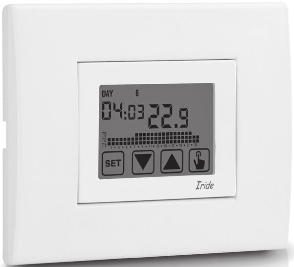
22 DISPLAY AND KEYBOARD 1 Day of the week (DAY 1= Monday) 2 Programming menu: : date/time and summer time setting : programs change mode (for automatic operating) : temperatures setting T1, T2, T3 : timing menu : advanced programming menu : not used : not used 3 Time and minutes 4 Load activation in summer mode/ cooling 5 Manual operation activation 6 Load activation in winter mode/heating 7 Measured environment temperature 8 Program on graphic for the current date (in automatic operation) 9 Off operation 10 Depleted battery indication (only batteries model) 11 Keyboard (active only if the device is inserted in the flush-mounting box)
23 Keyboard The keys carry out different functions on the basis of the device status and they will be described step by step in this user manual. Multipurpose keys are not built into the instrument, that is to say contemporary pressures of 2 or more keys. There are two types of pressure: - brief pressure - long pressure, with duration higher than 3 seconds During the press of a button, the display is blue. Attention: press the keys with your fingers; do not use sharp objects! Attention: the keys are not active until the instrument is not correctly inserted in the flush-mounting box. Cleaning the display To clean the display use a soft, lint-free cloth, without using excess force. INSTALLATION The chronothermostats of Iride series are designed for flush-mountig on 3 modules box (503 type). The chronothermostats must be installed at a height at about 1.5 m above the floor, away from direct sunlight, away from doors, windows, heat sources, locations with excess or total lack of ventilation. Install the white or anthracite grey cover according to your preferences by hooking it to the cogs of the device Make the connections by respecting the diagrams described in this manual. Fix the device inside the 3 modules box in compliance with the assembly diagrams described at the beginning of this instruction sheet. The accessories for the installation included in the package allow the mounting of the plates described in
24 the diagram adjustable cover plates and they are: - mount A - mount B (according to the needs it could be necessary to remove the side cogs) - mount AIR - couple of side BM plastic elements (both of white colour and grey colour) - couple of side elements VI (both of white colour and grey colour) - covers of white colour and anthracite grey colour. Attention: it s not possible to make no programming or to set parameters modification until the instrument is not correctly placed in the flush-mounting box. Clock setting Once the device is mains powered, synchronise the clock (time and date insertion). The parameters to enter are the following: seconds (only synchronisation at value 00), minutes, hours, year, month, day. Seconds synchronisation Minutes setting Time setting Year setting Month setting Day setting
25 Use the keys and to increase and decrease the values and the key to confirm and to move to the next parameter. Once all values are set, press for a long time (3 seconds) the key of the clock synchronisation. At this point the chronothermostat will begin to operate with the set default parameters (see page 42), displaying the day of the week, the time, the environment temperature and the graphic of the program on. HOUR DAY to exit the menu TEMPERATURE PROGRAM GRAPHIC Attention: To operate correctly the chronothermostat requires the time and date insertion. If once mains powered, no value is set within about 30 seconds, the chronothermostat begins to operate in off mode, displayed with the symbol. The time lack is displayed with flashing dashes ( : ). The chronothermostat remains in off operation condition until when the hour is not inserted, ensuring in this way the saving of the antifreeze temperature (6 C). In this condition, the pressure of any key reactivates the menu of date/time insertion for other 30 seconds about
 2.")
26 PROGRAMMING MENU With this menu it s possible to modify the following operating parameters: - Date and time - Automatic operation programs - Automatic operation temperatures - Timings - Advanced functions. 3s Time and date modification To modify the hour and the date set: 1. From normal operating display, press for a long time the key until the symbol starts flashing on field (2) 2. Press the key to access parameters modification. The seconds field starts flashing. Parameters sequence to set is: seconds* -> minutes -> hours -> year -> month -> day 3. Use the keys and to modify the values and the key to confirm moving to the next parameter. (*) for seconds it s possible only the synchronisatin at value Once all parameters are set, to exit and to go back to the programming menu, press a short time the key. To exit and to go back to the normal operating (automatic, manual) press for a long time the key or wait for the time-out expiration (30 seconds about). Inside this menu it s possible to modify the parameters for winter/summer time change. The procedure is described in a detailed way in the chapter Summer time change on page
27 Programs modification With this menu it s possible to modify the programming of the automatic operation. The device is configured to perform the program P1 from Monday to Friday and P2 on Saturday and on Sunday (the programs profile is described at the end of this manual on page 43-44) If this programming doesn t satisfy the user needs it s possible to change it. To modify the programming: 1. From the normal operation display, press for a long time the key until the symbol starts flashing on field (2) 2. Press briefly the key until the symbol flashes and press the key to access the parameters modification. 3. The programs page is displayed: the first day of the week (DAY 1) flashing, the current program (for example P1) of the current mode ( or ) and the corresponding profile of the program If the set program is good, move to the next day with the keys and If the set program is not good, press the key. The set program flashes: choose one program different among the 7 available by pressing the keys and If no program exactly satisfies the user s needs, choose any program which best meet them and press the key to access the modification of the program profile. On field (3) 00:00 appears while on field (7) flashes the temperature level (T1, T2 o T3) set for that specific time (00:00)
28 Use the keys and to change the temperature level and the key to move to the next hour. Set like this the desired level temperature for each hour of the day For each hour it s possible to delay the start of the regulation of 15, 30 or 45 After setting the temperature as described above, press for a long time the key to set a delay. The minutes field flashes (field 3): set with the keys and the delay and press the key to move to the next hour. 4. When the program satisfies the user s needs, go back to the days pressing twice the key and repeat for the other days of the week the operations just described. When all modifications have been performed, exit the programming menu pressing for a long time the key. 3s Temperatures T1, T2, T3 modification To modify the 3 temperatures of automatic operation: 1. From the normal operation display, press for a long time the key until the symbol starts flashing on field (2) 2. Press briefly the key until the symbol flashes. Press the key to access the parameters modification
29 3. The value of the flashing T1 temperature is displayed. Modify the value with the keys and and press the key to move to the modification of T2. 4. The value of the flashing T2 temperature is displayed. Modify the value with the keys and and press the key to move to the modification of T3. 5. The value of the flashing T3 temperature is displayed. Modify the value with the key and and press the key to go back to the page of T1 temperature. 6. Once all parameters are set, to exit and to go back to the programming menu, press for a short time the key. To exit and to go back to the normal operation press for a long time the key or wait for the time-out expiration (30 seconds about). Attention: the values of set temperatures must respect the condition: T1 T2 T3. In cooling mode T1 is not settable and equals off system
30 Timing setting This menu allows the setting of a timing on the current operating mode, expressed in hours and days. For further information about timings, see the chapter Timings: what they are on page 38. To set a timing: 1. From the normal operation display, press for a long time the key until the symbol starts flashing on field (2) 2. Press briefly the key until the symbol flashes and press the key to access the parameters modification. 3. The value of the timing currently set flashes (00= no timing). Enter the timing value (from 1 to 99) with the keys and and press the key to move to the measurement unit change (hours and days). 4. The measurement unit starts flashing (h0ur or day). Press the keys and to choose a timing in hours (h0ur) or days (day)
31 5. Once all parameters are set, to exit and to go back to the programming menu, press for a short time the key. To exit and to go back to the normal operation (automatic, manual) press for a long time the key or wait for the time-out expiration (30 seconds about). If a timing is active, the display shows the symbol. To interrupt a timing, access again the menu and set the value 00. Advanced functions menu With the ADV menu it s possible to modify the following operation parameters: - operating mode (heating or cooling) - regulation type (on-off or proportional) - parameters relative to regulation type - antifreeze temperature - password for key lock - system operation hours. To access the menu ADV: 1. From the normal operation display, press for a long time the key until the symbol starts flashing on field (2) 2. Press briefly the key until the symbol starts flashing and press the key to access the parameters modification 3. At this point the first parameter of the menu starts flashing: press the keys and to modify the parameter and the key to confirm and to move to the next parameter. To exit the parameters modification press the key
32 Operating mode This parameter allows to specify the operating mode of the chronothermostat, between winter/ heating ( ) and summer- cooling ( ). For further information about the operating mode see the chapter Regulation type on page 36. Regulation type (only for heating mode) For heating mode it s possible to choose between on/off regulation (Reg 0) or proportional (reg P). For further information about regulation type see the chapter Regulation type on page
33 Regulation parameters In case of on/off regulation the only parameter to set is the hysteresis (dif), which can have values between 0.1 C e 1 C. In case of proportional regulation the parameters to set are the regulation band (bnd) and the regulation period (PEr). For further information about how to choose these values see the chapter Regulation type on page 36. But remember that the preset settings are suitable for the most part of the situations: to change these settings only if it s really necessary. Antifreeze temperature (only for heating mode) For the heating mode it s possible to set a safety temperature (antifreeze temperature 0ff) to maintain also if the chronothermostat is switched off. It s possible to choose a value between 1 C and 10 C. It s also possible to deactivate the antifreeze function pressing the key until the display shows. _--. In this case, when the chronothermostat is switched off, no safety temperature is maintained. Password for key lock It s possible to set a key lock if the chronothermostat is installed in public places or however if you want to prevent anyone from modifying the operation parameters. To set a password, enter on field PAs a value between 001 and 999. To deactivate the password press the key until._ appears. When the keyboard is locked, the chronothermostat performs all its functions using the set regulation parameters
34 If the key lock is active and one key is pressed, the display shows for a few seconds the writing bl0c with flashing dashes: enter the password to unlock the keyboard, which will be locked for 30 seconds from the last pressure. System operation hours This page shows the total number of hours of the system operation (relais ON) for the current mode (indicated by the icons or ). The hour meter has got 4 digits and it s resettable pressing for a long time the key until 0000 appears. MANUAL OPERATION During manual operation the chronothermostat performs as a normal thermostat, adjusting on the basis of the Tm temperature (manual setpoint), independently from the day and the time where it is. The manual operation is signalled with the switch on of the symbol in the field (5). To move from the automatic operation to the manual one: 1. press briefly the key. In the field (7) the setpoint (Tm) currently set flashes 2. set the desired setpoint with the keys and and confirm with the key 3. at this point on field (7) the value of the environment temperature reappears and the instrument operates in manual. If you want to change the setpoint (Tm) press the key and repeat the points 2 and 3. To go back to the automatic operation press for a long time the key (for about 3 seconds)
35 Automatic operation Manual setpoint (Tm) setting Manual operation 3s OFF OPERATION In off mode the device doesn t perform any regulation (*) but it continues to display the day, the time and the measured temperature. (*) When in heating / winter mode the device maintains a minimum temperature - Toff antifreeze temperature - to avoid the freezing of the systems where the device is installed. Toff can have values between 1 C and 10 C or it can be completely shut down; in this last case the saving of minimum temperature is not guaranteed. The set default Toff is 6 C but it s possible to modify this value entering the ADV menu (see Antifreeze temperature on page 29). To switch the device off press the key until the symbol is displayed (field (9))
36 To reactivate the regulation, switching back to the operating (automatic or manual) which is before the switching off, press the key for about 3 seconds. 3s 3s Remotely switching off (battery powered model only) The battery powered Iride have got an input for the connection to a clean contact to whom to connect for example a telephone dialler to switch on or to switch off remotely the chronothermostat with their own telephone. The contact can have one of these two positions: - open à normal operation (according to the set programming) - closed à chronothermostat in off mode Remotely off status is displayed with the flash of the symbol on field (9) to differentiate it from the keyboard off status ( fixed on field (9)). Attention: remotely off status (closed contact) is more important than any other programming, so the instrument will be in off status until the contact doesn t switch back to the opened position
37 BACKLIGHTING MANAGEMENT The chronothermostats of the Iride series have got a backlit display with led. There are some differences between battery powered models and mains powered models. Battery Iride The battery powered model has got a backlighting of blue colour, which is activated only if they are inside any menu of programming or if any key is pressed. In normal operating status the backlight results off. This behaviour is not modifiable. Iride 230V~ The 230 V model has got a multicolor backlighting which can be configured according to the preferences user. The possible configurations for the backlighting are the following: RGB (RGB) in this case the backlighting changes following the difference between the measured temperature and the programmed setpoint. In particular, it will be: - blue, if the measured temperature is lower than the programmed setpoint of at least 0.5 C (or we are inside any programming menu) - green, if the difference between the measured temperature and the setpoint is, in absolute value, lower than 0.5 C (or if the device is in off mode) - red, if the measured temperature is higher than the setpoint of at least 0.5 C (or in case of probe error) BLUE (BLU) in this case the backlighting will be blue fixed GREEN (GRE), in this case the backlighting will be green fixed (blue inside programming menu) RED (RED), in this case the backlighting will be red fixed (blue inside programming menu) OFF (0FF), in this case the backlighting is always off (blue inside programming menu). Useful for example in bedrooms. It s possible to configurate the backlighting pressing the key for
38 seconds: in this way you access the configuration menu and it s possible to select rgb, blu, red, gre, 0ff. 3s MINIMUM AND MAXIMUM VALUE It s possible to display the measured values of minimum and maximum temperature. To display these values press the key (maximum value Hi) or (minimum value L0). During the display it s possible the resetting of these values pressing the key until 3 dashes appear in place of the temperature. SUMMER TIME CHANGE Summer time is the convention to step up of one hour the dials of the clocks during the summer period in order to prolong the lighting time in the late afternoon to the loss of the early morning. In European countries summer time starts the last Sunday of march and ends the last Sunday of october. The chronothermostat manages the summer/winter time change as follows: - increasing of one hour to move from winter time to summer time - decreasing of one hour to move from summer time to winter time The device is default configured to move from summer time the last Sunday of march at 2 o clock to go back to winter time the last Sunday of October at 3 o clock in accordance with Europe convention. However it s possible to deactivate the automatic time change or to change the date or the hour of the time change
39 To change settings: 1. Access the menu of time and date change, pressing for a long time the key until the symbol starts flashing. 2. Press the key to access the time and date modification. At this point, during the modification of any parameter (seconds, minutes, hour, year, month or day) press for a long time the key until the display shows the writing Aut0 appears on field (3). 3. Choose with the key and the automatic time change activation (Aut0 0n) or its deactivation (Aut0 0FF) and confirm with the key 4. If 0FF we go back to the date/time change; if 0n the current setting for the passage to summer 3s time is displayed (indicated with the symbol ). In the example: a. the Sunday (7) of the last week (LA) of march (03) at 2 o clock (02) b. if it s necessary change the parameters with the keys and and move to the next parameter with the key. The sequence requires the insertion of: i. day (1 7) of the week ii. the week of the month (first, second, third, fourth, last LA) iii. the month (1 12) iv. iv. the hour 5. Press the key the current setting for the passage to the winter time is displayed (indicated with the symbol ). In the example: a. the Sunday (7) of the last week (LA) of october (10) at 3 o clock (03) b. if it s necessary change the parameters with the keys and and move to the next parameter with the key. The sequence requires the insertion of: i. day (1 7) of the week ii. the week of the month (first, second, third, fourth, last LA) iii. the month (1 12) iv. the hour
40 6. Once all parameters are set, to exit and to go back to the programming menu, press for a short time the key. To exit and to go back to the normal operation press for a long time the key or wait for the time-out expiration (30 seconds about). REGULATION TYPE Iride has got two types of regulation: On/off regulation During on/off regulation the chronothermostat measures once a minute the environment temperature and it carries out the regulation on the basis of the following logic: heating mode cooling mode relay ON relay ON relay OFF SET-DIFF SET relay OFF SET SET+DIFF Temperature increasing Temperature increasing where SET represents the setpoint and DIFF the hysteresis (useful to avoid continuous switches on/switches off dangerous for the system in proximity to the reaching of the setpoint. Proportional regulation (only in heating) In heating mode, the on/off regulation is available and also the proportional regulation which in some systems allows a more precise regulation to obtain a constant temperature. This regulation requires to specify two parameters: the band, which represents the temperature values with whom to perform the proportional regulation. The band is centered on the setpoint and it can have values between 0,5 C and 5 C; outside these values the heating will be always on (if setpoint-band > environment temperature) or always off (if setpoint + band < measured temperature)
41 the regulation period which represents the duration of the regulation cycle (activation time + deactivation time of heating) and it can have values of 10, 20 or 30 minutes. During the operating, at the beginning of the regulation period, the instrument measures the environment temperature and it compares it with the programmed setpoint; on the basis of this difference the activation time is calculated (and consequently the deactivation time). The more the measured temperature is next to the setpoint value band, the more the activation time will be predominant in comparison with the deactivation time; on the contrary, the more the measured temperature is next to the setpoint value + band, the more the deactivation time will be predominant in comparison with the activation time). Once regulation period is passed, the device compares again the environment temperature with the setpoint and it updates the activation and deactivation times for the new period. The result of the proportional regulation is subordinated to the correct selection of the parameters. Select the value of the regulation type as follows: 10 for low thermal inertia systems (fan-coil) 20 for medium thermal inertia systems (aluminium radiators) 30 for high thermal inertia systems (cast-iron radiators) Select the regulation band value as follows: broad band (5 C) for systems with high thermal gradient narrow band (0.5 C) for systems with low thermal gradient Attention: the device is default configured to operate in on/off with hysteresis set at 0.3 C. This configuration is suitable for the most part of the situations and for this reason it s advisable to modify it only in particular situations. To modify the regulation type, dif value (on/off regulation), band and period (proportional regulation) see chapter Regulation parameters at page
42 Emergency regulation (winter mode only) The device performs a regulation of emergency if an error occurs during the reading of the probe or in case of time loss. In case of probe error, if the antifreeze function is not excluded, the device activates the load for 10 minutes every 4 hours. The display shows the writing Err on field (7). In case of time loss (because of depleted batteries or blackout of a duration higher than the charge reserve) the device restarts from the off mode, adjusting on the basis of the antifreeze temperature, if it hasn t been deactivated before. Reset date/ time to go back to the normal operation (programs modifications and settings remain memorized). TIMINGS: WHAT THEY ARE Timings allow to maintain the current operation (automatic, manual, off) for a certain period (times or days) and once passed the chronothermostat changes the operating mode, as explained below. The timed operations are the following: Timed automatic If in automatic status you set a timing, such off status will be maintained until the end of the timing operation, will then switched to off mode. Timed manual If in manual status you set a timing, such off status will be maintained until the end of the timing; operation will then switched to automatic mode
43 Timed off If in off status you set a timing, such off status will be maintained until the end of the timing, operation will then switched to the one active before the deactivation (automatic or manual). If you set a timing, the display shows the symbol. Attention: the timing is calculated in minutes and for this reason if for example you set a timing of 3 days at 12:15 on Tuesday it will expire at 12:15 on Friday. Attention: the timings can end before their programmed expiration if one of these actions occur: - time/ date modification (modification of the summer time change included) - manual modification of the operating mode - switching of digital input (only for battery models) - change of the operating logic from winter to summer (or viceversa) To set a timing, see chapter Timing setting at page
 or to extract the chronothermostat from the wall-mounted base and reinsert it (battery versions) 2.")
 signals the status of depleted batteries switching on the symbol (field (10)) and making the display to flash.")
44 DEVICE RESET If you want to erase all performed settings and to recharge the default values, proceed as follows: 1. to switch off and to switch on the power of the chronothermostat (230 V versions) or to extract the chronothermostat from the wall-mounted base and reinsert it (battery versions) 2. during the flashing of the keys press the key until the display shows the writing def. Default values are indicated on page 42 of this manual. BATTERY REPLACEMENT The model Iride (batteries) signals the status of depleted batteries switching on the symbol (field (10)) and making the display to flash. In this status the regulation is always guaranteed, but it s advisable to replace the batteries as soon as possible! (*) If the charge level of batteries further decreases, the chronothermostat enters into less consumption mode, it switches off the display and it doesn t perform any regulation. (*) Remove the depleted batteries and replace them with the new ones in a maximum time of one minute (charge reserve) to avoid to lose the settings of date and time (the performed programmings on the contrary remain memorized even if this limit is surpassed). Attention: after batteries replacement, the display will switch on within 15 seconds at max. Dispose of the used batteries observing the laws in force in relation to the disposal of hazardous waste. The removal of the device occurs by pulling on the convexity of the frame (see figure)
45 REFERENCE STANDARDS Compliance with Community Directives 2014/35/EU (LVD) 2014/30/EU (EMCD) is declared in reference to the harmonized standards: EN , EN
46 DEFAULT VALUES parameter min max step default winter manual setpoint 2.0 C 35.0 C 0.1 C 21 C summer manual setpoint 2.0 C 35.0 C 0.1 C 25 C T1 winter 2.0 C T2 0.1 C 15.0 C T2 winter T1 T3 0.1 C 18.0 C T3 winter T C 0.1 C 21.0 C T2 summer 10.0 C T3 0.1 C 23.0 C T3 summer T C 0.1 C 25.0 C antifreeze temperature 1.0 C 10.0 C 0.1 C 6.0 C operating mode winter summer - winter regulation type ON/OFF PROP - ON/OFF ON/OFF hysteresis 0.1 C 1.0 C 0.1 C 0.3 C proportional band 0.5 C 5.0 C 0.1 C 0.5 C proportional period password (deactivated) winter hour meter summer hour meter winter/summer time, enable ON OFF - ON winter/summer time change Summer: LAST DAY7 march 02:00 Winter: LAST DAY7 october 03:00 activation delay timed operations 0h 99d 1h 0h
47 WINTER PRESET PROGRAMS T3 T2 P1 T T3 T2 P2 T T3 T2 P3 T T3 T2 P4 T T3 T2 P5 T T3 T2 P6 T T3 T2 P7 T
48 SUMMER PRESET PROGRAMS T3 T2 P1 T T3 T2 P2 T T3 T2 P3 T T3 T2 P4 T T3 T2 P5 T T3 T2 P6 T T3 T2 P7 T
49
50
51
52 V3IS Vemer S.p.A. I Feltre (BL) Via Camp Lonc, 16 Tel Fax info@vemer.it - web site:
Cronotermostato Digitale
 Cronotermostato Digitale CHRONOS KEY Manuale d Uso User Manual DIGITAL PROGRAMMABLE THERMOSTAT Index Dimensions Page 4 Connection diagram Page 4 Safety warnings Page 5 Technical specifications Page 6 Display
Index. English. English User Manual Eco.X
 Index Safety Warnings Page 18 Technical Specifications Page 18 Display and Programming Page 19 Initial start up / Reset Page 21 Clock Setting Page 22 Language Selection Page 22 Automatic Operation Page
SINGLE ZONE CLIMATE ZONING SYSTEM. Technical Manual. Polyaire Pty Ltd
 SINGLE ZONE CLIMATE ZONING SYSTEM Technical Manual Polyaire Pty Ltd 11-13 White Road GEPPS CROSS South Australia, 5094 Tel: (08) 8349 8466 Fax: (08) 8349 8446 www.polyaire.com.au CONTENTS Features 1 Application
EVF 300 series. Controllers for electric bread and pizza ovens, with touch-keys, in split version and which can be integrated into the unit.
 EVF 300 series Controllers for electric bread and pizza ovens, with touch-keys, in split version and which can be integrated into the unit. Installer manual ENGLISH Code 144F300E114 Page 1 of 62 Important
Radio Thermostat Clock
 Radio Thermostat Clock Installation & User Instructions Part number: ZU0800009 80.10.1375.7_feeling_ks_fer_en.indd 1 18.04.2013 11:25:42 Table of contents Safety instructions... 3 Product details... 4
EN Wireless programmable thermostat
 EN Wireless programmable thermostat Contents 1. Installation... 31 2. Description... 32 EN 3. Wireless association... 33 4. Configuration... 34 CF01 - Correcting the temperature measured... 34 CF02 - Temperature
TP7001 Range Electronic 7 Day Programmable Room Thermostat. Danfoss Heating. Installation Guide
 TP7001 Range Electronic 7 Day Programmable Room Thermostat Danfoss Heating Installation Guide For a large print version of these instructions please call Marketing on 0845 121 7400. Certification Mark
Programmable Room Thermostat With RF
 Salus RT500RF Manual:89 10/7/10 23:43 Page 1 Programmable Room Thermostat With RF Instruction Manual Model No RT500RF 2 Salus RT500RF Manual:89 10/7/10 23:43 Page 2 PRODUCT COMPLIANCE This product complies
SAUTER flexotron RDT405 Manual
 SAUTER flexotron 400 - RDT405 Manual P100012100 Table of contents DISCLAIMER The information in this manual has been carefully checked and is believed to be correct. Fr. Sauter AG however, makes no warranties
APOLO DC B Electric Thermal Radiators
 APOLO DC B Electric Thermal Radiators Large LCD control Display Daily and weekly programming INSTRUCTIONS FOR USE, INSTALLATION AND ASSEMBLY 1 INDEX 1. INTRODUCTION... 1 2. LOCATION... 1 3. ELECTRIC CONNECTION...
Thank you for purchasing this product. If installing for someone else, please ensure that the instructions are handed to the householder.
 Instruction Manual TPST501 (569568) - BOSS TM Universal mable Room Thermostat (Wired) (7 day, 5/2 day and 24 hour programme options) Thank you for purchasing this product. If installing for someone else,
Operating Instructions. Room temperature controller with clock
 Operating Instructions Room temperature controller with clock 0389.. Table of contents Normal view in the display... 3 Basic operation of the room temperature controller... 3 The individual displays and
ZoneTouch V2 Zone Control System User Manual
 ZoneTouch V2 Zone Control System User Manual www.polyaire.com.au 2014 Polyaire Pty Ltd II ZONEMASTER ZONETOUCH V2 ZONE CONTROL SYSTEM - User Manual TABLE OF CONTENTS 1) Features 2 2) Wall Controller Layout
Luminaire installation box Surface-mounted box Ceiling installation box
 -Smart PTM Ambient light sensor and motion detector for constant lighting control uminaire installation box Surface-mounted box Ceiling installation box Overview: -SMART PTM i is an ambient light sensor,
DLP200M 2 Relay Module for Heating and Cooling Plants
 Product Sheet TH6.24 Thermostat Type DLP200M DLP200M 2 Relay Module for Heating and Cooling Plants The DLP 200 M is a relay module for activation of loads (namely thermal actuators or circulators) in wireless
2 CHANNEL RECEIVER DISPLAY POTENTIOMETER COM2 NC2 NO2
 2 CHANNEL RECEIVER RECTSHIVE915-DX Please read this manual carefully before installing the product. 1 DESCRIPTION Receiver Rolling Code, 2 channels with dry contact relay output 20A a 12 Vdc. Programming
DLP600M 6+1 Relay Module for Heating and Cooling Plants
 Product Sheet TH6.25 Thermostat Type DLP600M DLP600M 6+1 Relay Module for Heating and Cooling Plants The DLP 600 M is a relay module for activation of loads (namely thermal actuators or circulators) in
Comfort System T-32-P Universal Thermostat. Operation Manual
 TM Comfort System T-32-P Universal Thermostat TM O Operation Manual Your new Comfort System T-32-P Universal Thermostat has been built using the highest quality components and design currently available.
42 Freestanding Infrared Multi Touch Screen Kiosk User s Manual
 42 Freestanding Infrared Multi Touch Screen Kiosk User s Manual Manual Version L42HD-T2.2 Safety Instructions Please keep the display away from any heat sources such as radiators or direct sunlight. Place
SCS318. User Instructions. SCS318 comprising of SCS317 7 Day Wireless Programmable Room Thermostat and SSR303 Receiver
 SCS318 User Instructions SCS318 comprising of SCS317 7 Day Wireless Programmable Room Thermostat and SSR303 Receiver Programmable room thermostats are widely recognised as one of the best ways in which
2-output DALI controller
 87045 LIMOGES Cedex Telephone: (+33) 05 55 06 87 87 - Fax: (+33) 05 55 06 88 88 -output DALI controller Page. Use.... Technical features... 3. Overall dimensions.... 4. Connection... 5. Installation...3
Weekly Time Switch. Rated time Time setting range Time division 24 hrs x 7 days 00:00 to 23:59 1min
 Weekly Time Switch Easy Programming with Large LCD Display and Interactive Functions Programming for 24 hrs x 7 days using just five switches. Sixteen program steps available. Power supply freely selectable
2 2 Relay outputs. M DIN W72 H7mm. LE7 Weekly/Yearly timer
 LE7M-2 W72 H72mm, Weekly/Yearly Timer Features Easy to check and change the program setting Customizable weekly or yearly unit time setting and control by user Includes daylight saving time function Built-in
2 WIRE - LOOP POWERED TRANSMITTER FOR PT100 AND NI100 PROBES
 EN K20RTD 2 WIRE - LOOP POWERED TRANSMITTER FOR PT00 AND NI00 PROBES General Description The K20RTD instrument converts a temperature signal read by a PT00 (EN 60 75) or NI00 probe with connection by 2,
LCD Thermometer / Clock S No. 1253
 Installation and Operating Manual LCD Thermometer / Clock S No. 1253 The 3 fold thermometer with crystal clock is purpose build for the mounting in caravans, boats and intervention vehicles. Please read
Inserting the batteries. Basic settings of the remote control
 Inserting the batteries Procedure prior to first use or when changing batteries Remove the back plate to expose the battery tray. Insert 2 x AA 1.5V alkaline batteries. Ensure the polarity of the batteries
For installation queries contact Customer Services (0) TCR IP 4 Operating instructions
 TCR IP 4 Operating instructions") For installation queries contact Customer Services +49 - (0)3 69 25-9 00 90 kundenservice@rutenbeck.de TCR IP 4 Operating instructions GB Device overview External buttons (for manual switching) Temperature
For installation queries contact Customer Services +49 - (0)3 69 25-9 00 90 kundenservice@rutenbeck.de TCR IP 4 Operating instructions GB Device overview External buttons (for manual switching) Temperature
User Manual CC DC 24 V 5A. Universal Control Unit UC-1-E. General Information SET. Universal Control Unit UC-1 Of Central Lubrication PAUSE CONTACT
 Universal Control Unit UC-1-E User Manual General Information Universal Control Unit UC-1 Of Central Lubrication CC DC 24 V 5A / M 15 SL /MK 31 M Z 30 General Information Contents Universal Control Unit
REGO Start&Go USER MANUAL
 REGO Start&Go USER MANUAL Version 0 Rev. B of 03/03/16 Page 1 of 15 Introduction The purpose of the manual is to describe all of the steps required to commission and correctly operate the REGO Start&Go
Thank you for purchasing this product. If installing for someone else, please ensure that the instructions are handed to the householder.
 Instruction Manual TPSE201 (181422) - BOSS TM Universal Programmer TPSE101 (569565) - BOSS TM Universal Timeswitch Thank you for purchasing this product. If installing for someone else, please ensure that
INSTALLATION & OPERATING INSTRUCTIONS SINGLE/TWO CHANNEL 24HR/7 DAY TIMER. Cat No. TR671/TR672TOP
 SINGLE/TWO CHANNEL 24HR/7 DAY TIMER Cat No. TR671/TR672TOP INSTALLATION & OPERATING INSTRUCTIONS TR671/TR672TOP 24Hr/7 Day 1/2 Channel Digital TOP Module (without Power Supply) Please read the instructions
4 Wiring Brochure Wiring and installation of specific control
 - Wiring Brochure tekmarnet 4 User Switch 480 W 480 09/09 1 Information Brochure Choose controls to match application 2 Application Brochure Design your mechanical applications 3 Rough In Wiring Rough-in
M150SP USER S AND INSTALLER S MANUAL. v2.0 REV. 03/2017
 M150SP USER S AND INSTALLER S MANUAL v2.0 REV. 03/2017 00. CONTT 01. SAFETY INSTRUCTIONS INDEX 01. SAFETY INSTRUCTIONS STANDARDS TO FOLLOW 02. THE DEVICE TECHNICAL SPECIFICATIONS VISUAL ASPECT CONNECTORS
All the energy of your home, in an App!
 All the energy of your home, in an App! The smart home system for managing wireless thermostats energy meters smart sockets Rialto, simplicity with total comfort Simple installation Simple configuration
RT505TX Programmable. The RT505TX can be used with any of these receivers RXBC605 RXWBC605 RXVBC605 RXST MHz
 RT505TX T RT505 T505TX TX RT505TX RT505TX RT505TX 5TX Programmable Room o Thermostat RXBC605 RXRT505 RXWBC605 RXST625 RXVBC605 The RT505TX can be used with any of these receivers 868MHz RT505TX RT505TX
RADIO RECEIVER RGBW CONTROLLING LED STRIP COMMON ANODE
 TELECO AUTOMATION SRL - Via dell Artigianato, 16-31014 Colle Umberto (TV) ITALY TELEPHONE: ++39.0438.388511 FAX: ++39.0438.388536 - www.telecoautomation.com This document is the property of Teleco Automation
TDDFM14 OWNER S MANUAL
 TDDFM14 OWNER S MANUAL Table of Contents 3 Installation Features System Selector Switches 6 10 Connecting Wires and Mounting Thermostat 10 Operation (Programming) Programming/Setting Clock Personal Program
Operating instructions Electronic preset counter Type series 717
 Operating instructions Electronic preset counter Type series 717 1. Description 5.98.3_gb 6-digit adding/subtracting counter with two presets Very bright 8mm high LED display Counting and preset range
PLC Control Unit for a CSM-E Electrical Compact Clean Steam Generator
 3.635.5275.254 IM-P486-18 CH Issue 3 PLC Control Unit for a CSM-E Electrical Compact Clean Steam Generator Installation, Start-up and Operation Manual 1. Safety information 2. General product information
KNX Dimmer RGBW - User Manual
 KNX Dimmer RGBW - User Manual Item No.: LC-013-004 1. Product Description With the KNX Dimmer RGBW it is possible to control of RGBW, WW-CW LED or 4 independent channels with integrated KNX BCU. Simple
User interface. Abbreviations / Meanings
 RG66012649 User interface Contents Page Abbreviations / Meanings Abbreviations / meanings... 2 Button Identification... 3 On-screen Indicators... 4 Quick Start... 5 Setting the time and day... 5 Changing
AEROTRAK PORTABLE AIRBORNE PARTICLE COUNTER MODEL 9110 QUICK START GUIDE
 AEROTRAK PORTABLE AIRBORNE PARTICLE COUNTER MODEL 9110 QUICK START GUIDE Thank you for purchasing a TSI AeroTrak Model 9110 Portable Airborne Particle Counter (particle counter). This guide will help you
MG-XV operating instruction. Measuring of norm signals, 4-8-digit. Panel instrument type MG-BV Construction instrument type MG-AV
 MG-XV operating instruction Measuring of norm signals, 4-8-digit Panel instrument type MG-BV Construction instrument type MG-AV Contents 1. Brief description... 3 2. Safety instructions... 3 2.1. Proper
ULTRA-VANSTAT WIRELESS PROGRAMMABLE THERMOSTAT FOR CARAVANS
 ULTRA-VANSTAT WIRELESS PROGRAMMABLE THERMOSTAT FOR CARAVANS NOT SUPPLIED PROGRAMMER / TRANSMITTER RECEIVER THIS DOMESTIC STYLE WIRELESS 7 DAY PROGRAMMABLE HEATER CONTROL REPLACES THE TRUMA ULTRAHEAT SWITCH
VLC-3 USER'S MANUAL. Light Program Controller. M rev. 04 K rev. 00 & ( ( 5, 352*5$0 1 : $ 2 ' 6(77,1*6 )81&7,216
81&7,216") Light Program Controller VLC-3 USER'S MANUAL +50,1 +50,1 1 : $ ' 2 7. 6 8 ' 5, 7 6 6. $ ( 3 352*5$0 0,16(& )81&7,216 6(77,1*6 & 8 5 5 ( 1 7 3 ( 5, 2 ' M 890-00189 rev. 04 K 895-00406 rev. 00 GENERAL...
Light Program Controller VLC-3 USER'S MANUAL +50,1 +50,1 1 : $ ' 2 7. 6 8 ' 5, 7 6 6. $ ( 3 352*5$0 0,16(& )81&7,216 6(77,1*6 & 8 5 5 ( 1 7 3 ( 5, 2 ' M 890-00189 rev. 04 K 895-00406 rev. 00 GENERAL...
Litile34 OPERATION MANUAL
 Litile34 OPERATION MANUAL Seamless Tiled Panel Wall Solution for Large Area Digital Signage Display (1st Edition 3/25/2009) All information is subject to change without notice. Approved by Checked by Prepared
KNX Technical Reference Manual Busch-EnergyControl
 0073-1-7703 Rev. 02 05.2011 KNX Technical Reference Manual Busch-EnergyControl 6762-500 Efficiency with a future Less consumption and fewer costs pay off for people and the environment. You only need the
Installation and User Guide 458/CTR8 8-Channel Ballast Controller Module
 Installation and User Guide 458/CTR8 8-Channel Ballast Controller Module Helvar Data is subject to change without notice. www.helvar.com i Contents Section Page Introduction 1 Installation 2 1. Attach
Z-D-IN. RS485 Modbus Module 5 Digital Inputs
 S SENECA Z-PC Line EN Installation Manual Contents: - General Specifications - Technical Specifications - Installation Rules - Electrical connections - Modbus connection rules - DIP-switches Settings -
System pro M DT1-IK DT1-IK/24V DT1-IK/DCF DT2-IK 2CSM204275R0611 2CSM441017D5601 2CSM204285R0611 2CSM204295R0611 2CSM204325R0611
 DT1-IK 2CSM204275R0611 DT1-IK/24V 2CSM204285R0611 DT1-IK/DCF 2CSM204295R0611 DT2-IK 2CSM204325R0611 System pro M 2CSM441017D5601 GB WEEKLY DIGITAL TIME SWITCH + PROGRAMMING KEY I INTERRUTTORE ORARIO DIGITALE
Standard RS232 RS ma
 1 / 5 CONTROL AND VISUALIZATION OF AC CURRENT IN SINGLE PHASE LINES BY EXTERNAL SHUNT Function Operating mode Current control Frequency control DC component control Shunt Timer Resolution Current precision
2 2 Relay outputs. M DIN W72 H7mm. LE7 Weekly/Yearly timer
 Weekly/Yearly Timer W72 H72mm, Weekly/Yearly timer Features Easy to check and change the program setting Customizable weekly or yearly unit time setting and control by user Includes daylight saving time
Weekly Timer. Mounting track 50 cm (1.64 ft) length PFP-50N 1 m (3.28 ft) length PFP-100N
 length PFP-50N 1 m (3.28 ft) length PFP-100N") Weekly Timer 1/4 DIN Size Timer Features Prompted Programming and Large LCD Display 24 hours x 7 days programming using just 5 switches 16 program steps and cycle operation Two independent 15 A control
Weekly Timer 1/4 DIN Size Timer Features Prompted Programming and Large LCD Display 24 hours x 7 days programming using just 5 switches 16 program steps and cycle operation Two independent 15 A control
Data Sheet - DARWIN temperature controllers
 D40H022 Ed.04 GB Data Sheet - DARWIN temperature controllers - Quick Selection Guide Relay outputs Inputs Options Panel Compressor Defrost Fan Auxiliary Temperature control End of defrost temperature (a)
INSTRUCTION & INSTALLATION GUIDE
 Digital electric radiator INSTRUCTION & INSTALLATION GUIDE 2 Introduction harmoni digital electric radiators are programmable with an exclusive electronic temperature programmer and manufactured with quality
TUC: Universal thermostat
 Product data sheet 3.1 21.700 TUC: Universal thermostat How energy efficiency is improved Control, monitoring and limiting according to needs and with no auxiliary energy. Features Regulates and monitors
PL2410W LCD Monitor USER'S GUIDE.
 PL2410W LCD Monitor USER'S GUIDE www.planar.com Content Operation Instructions...1 Safety Precautions...2 First Setup...3 Front View of the Product...4 Rear View of the Product...5 Quick Installation...6
CURRENT INJECTION RELAY TESTER CR-100. ( Code P60212 (770081) ) INSTRUCTIONS MANUAL ( M / 05A ) (c) CIRCUTOR S.A.
 ) INSTRUCTIONS MANUAL ( M / 05A ) (c) CIRCUTOR S.A.") CURRENT INJECTION RELAY TESTER CR-100 ( Code P60212 (770081) ) INSTRUCTIONS MANUAL ( M 981 329 / 05A ) (c) CIRCUTOR S.A. ---- CURRENT- TIME TRIP TESTER CR-100 --------------- Page. 2 CURRENT INJECTION
CURRENT INJECTION RELAY TESTER CR-100 ( Code P60212 (770081) ) INSTRUCTIONS MANUAL ( M 981 329 / 05A ) (c) CIRCUTOR S.A. ---- CURRENT- TIME TRIP TESTER CR-100 --------------- Page. 2 CURRENT INJECTION
SAFETY WARNINGS AND GUIDELINES
 SAFETY WARNINGS AND GUIDELINES Please read this manual thoroughly, paying extra attention to these safety warnings and guidelines: Do not expose this monitor to water or moisture of any kind. Do not handle
Operating instructions. Universal timer switch display
 Operating instructions 1. Function The Time Switch display is a system component and is installed in a box as per DIN 49073 (deep box recommended) in conjunction with the Time Switch insert. The unit facilitates
7 Day Digital Programmer 3 Channel Surface Mount
 7 Day Digital Programmer 3 Channel Surface Mount Model: TRT038N Installation & Operating Instructions 1. General Information These instructions should be read carefully and retained for further reference
LUNA 129 star-time
 310 248 01 LUNA 129 star-time 129 0 700 Dämmerungsschalter Bedienungsanleitung 3 12 Twilight switch Operating instructions 13 22 Interrupteur crépusculaire Mode d emploi 23 32 Schemerschakelaar Gebruiksaanwijzing
Defrost Control Installation and Programming of Version 3.1 Cards
 Defrost Control Installation and Programming of Version 3.1 Cards INDEX 1. Introduction 2. Installation 3. Operation 4. Programming 5. Description Lists 6. Configuration Sheet NOTE: throughout the text,
OLED THE PERFECT HIGH-RESOLUTION DISPLAY
 OLED THE PERFECT HIGH-RESOLUTION DISPLAY ST-Box 300 ST-Box 200 ST-Box 200 F OLED ST 961 ST 961 ST-Box 100 OLED ST 900 ST 961 Commander 43 2 OLED technology A NEW GENERATION OF COMPACT DISPLAYS Störk-Tronic
ST625TX Digital Room Thermostat
 ST625TX Digital Room Thermostat RXBC605 RXST625 RXWBC605 RXVBC605 RXRT505 The ST625TX can be used with any of these receivers 868MHz PRODUCT COMPLIANCE This product complies with the essential requirements
UDC100 Universal Digital Controller. Specification. Overview. Features. Features, continued /99 Page 1 of 4
 UDC100 Universal Digital Controller 51-52-03-29 11/99 Page 1 of 4 Specification Overview The UDC100 Universal Digital Controller is a microprocessor-based 1/4 DIN low cost temperature controller. It combines
DUCATI SISTEMI S. P. A. DUCA47-96 USER MANUAL
 DUCATI SISTEMI S. P. A. DUCA47-96 USER MANUAL Introduction The instrument DUCA47-96 is a digital multimeter for panel mounting that allows the measurement of the principal electrical parameters in three-phase
estat20 Electronic Humidistat with remote sensor head Technical data Electrical data Humidity Temperature +125 C
 Galltec ess- und Regeltechnik GmbH EA ensortechnik GmbH D-71145 Bondorf. Germany D-07987 ohlsdorf-teichwolframsdorf. Germany Tel. +49 (0)7457-9453-0. Fax +49 (0)7457-3758 Tel. +49(0)3661-62704-0. Fax +49(0)3661-62704-20
Operating instructions III / 2004
 Operating instructions III / 2004 Light sensor TOUCH DIM LS LI OSRAM GmbH Costumer-Service-Center (CSC) Germany Steinerne Furt 62 86167 Augsburg, Germany www.osram.com www.osram.de Tel. : (+49) 1803 /
PLL2210MW LED Monitor
 PLL2210MW LED Monitor USER'S GUIDE www.planar.com Content Operation Instructions...1 Safety Precautions...2 First Setup...3 Front View of the Product...4 Rear View of the Product...5 Quick Installation...6
HS-509 VIBRATION TRIP MODULE
 HS-509 VIBRATION TRIP MODULE 1. Overview The HS-509 is a configurable trip amplifier capable of accepting a 4-20mA signal from a HS-420 sensor and providing two trip action relay outputs along with an
LINK-RAY TM MODULATORS FOR CONSTANT- VOLTAGE. LinkRay Modulators 12 V / 24 V Constant-voltage Applications MODULATORS
 MUSIUM RESTAURANT SOUVENIR SHOP EXIT LinkRay Modulators 12 V / 24 V Constant-voltage Applications LINK-RAY TM MODULATORS FOR CONSTANT- VOLTAGE LINK-RAY TM MODULATORS FOR CONSTANT-VOLTAGE APPLICATIONS 186755
MODE MENU /F1 /F2 F3 F4 PLCMHD80
 MODE MENU /F1 /F2 F3 F4 PLCMHD80 ! To insure best use of the unit, please read the user s manual carefully CAUTION 1. Do not use any damaged or leaking battery, if using a battery to power. 2. Do not expose
Thank you for purchasing this product. If installing for someone else, please ensure that the instructions are handed to the householder.
 Instruction Manual TPSRF51 (957707) - BOSS TM Universal RF Programmable Room Thermostat (Wireless) (7 day, 5/2 day and 24 hour programme options) Thank you for purchasing this product. If installing for
AK-PVE4 Operating Instructions. Measuring of norm signals in wall-type units. Performance:
 AK-PVE4 Operating Instructions Measuring of norm signals in wall-type units 1 2 P Performance: Digit heights: 20 mm Colour: red Display range: -999 9999 Wall-type housing: light grey made of ABS-plastic
Gamma instabus. Technical product information
 Gamma instabus Technical product information Universal dimmer N 554D31, 4 x 300 VA / 1x 1000 VA, AC 230 V Universal dimmer N 554D31 Control of dimmable lamps, including LED without minimum load Output
Sensopress LCD Special English
 Sensopress LCD Special English edition 2-09/2004 - code 5878 1/16 Sensopress LCD with sensor Power Supply Voltage 117 V~ 50 60 Hz 230V~ 50 60 Hz Code TSL00X0100 TSL00Y0100 Consumption 5,5 VA Display LCD
Intelligent Security and Fire Ltd
 User Manual Product ranges covered by this manual Vi-P14 Vi-P14A Document Reference Date Firmware Vi-Q4C1 Viq601a.doc 26/11/2009 From Viq001a21 Videoswitch Telephone 01252-851510 Ocean House, Redfields
XTM72E & F Real-Time Clock Modules
 Capricorn Controls Ltd Data & Application Notes Page 1 of 8 XTM72E & F Real-Time Clock Modules Originally designed to compliment our wide range of Gen-Set controls, these DC powered Real-Time-Clocks have
Owner's Manual. TOUCH SCREEN CONTROLLER for Air Conditioning Control System. Model BMS-CT5120UL. English
 TOUCH SCREEN CONTROLLER for Air Conditioning Control System Model BMS-CT5120UL English Contents 1 Precautions for safety.................................................. 5 2 Main functions........................................................
SceneStyle2 User Guide
 SceneStyle2 User Guide Mode Lighting (UK) Limited. The Maltings, 63 High Street, Ware, Hertfordshire, SG12 9AD, UNITED KINGDOM. Telephone: +44 (0) 1920 462121 Facsimile: +44 (0) 1920 466881 e-mail: website:
Model IQ4-PC User Manual Revision Date:
 Basic Specifications Supply Volts 230V 50/60Hz ±15% 115V 50/60Hz ±15% 24V DC (isolated) ±15% Power Consumption Max. 3VA (IQ4-PC-R0) Max. 6VA (IQ4-PC-R2-PSI24-RT) Operating Temperature -5 ~ +60 C Operating
FW/S Digital time switch 2CDG120039R0011 D GB F I E NL. Installation and operating instructions FW/S DCF antenna GPS antenna SELV MENU
 309594 FW/S 8.2.1 Digital time switch 2CDG120039R0011 GB Installation and operating instructions SELV DATA D GB F I E NL C1 C2 C3 C4 ESC C5 C6 C7 C8 OK FW/S 8.2.1 DCF antenna GPS antenna ESC MENU OK Set
ST9100C User Guide. Features
 Features Easy to use slider and buttons combined with LoT Technology and an OK button, allows you to confi rm changes and stay in control. PLEASE RESPECT YOUR ENVIRONMENT! Take care to dispose of this
Sevenlogic Comfort Timer Switch
 Operating manual Sevenlogic Comfort Timer Switch RoHS compliant 2011/65/EU General safety instructions...1 Technical data & included with delivery...2 Electrical connection...2 Assembly...3 Setting inching
Dimmers SЕRIES. Kitchen light control. Bedroom light control. Living room light control
 Kitchen light control Bedroom light control 15 SЕRES iving room light control ighting control in corridors (for hotels, offices and hospitals) FDER reserves the right to alter characteristics at any time
Operating instructions - High Performance LED Timer / / /
 Operating instructions - High Performance LED Timer 0 742 201/ 0742 202/ 0 742 251/ 0 742 252 Your tico 742 timer is a powerful instrument which can be field configured to fit a wide variety of applications.
Tech Support: Customer Service: General Tech Questions: Tech Docs:
 Tech Support: 1-800-407-4545 Customer Service: 1-800-523-2462 General Tech Questions: Tech_Services@beainc.com Tech Docs: www.beasensors.com BR3-X Programmable 3 Relay Advanced Logic Module & Restroom
Installation Operation Maintenance
 Installation Operation Maintenance Rooftop Energy Recovery Module for TKD / TKH / WKD / WKH YKD / YKH / DKD / DKH # 125-155-175-200 250 265-290-340 # 275-300-350-400-500-600 April 2011 RT-SVX42B-E4 General
MONOPRICE. 27" WQHD Monitor. User's Manual P/N 24659
 MONOPRICE 27" WQHD Monitor P/N 24659 User's Manual CONTENTS SAFETY WARNINGS AND GUIDELINES... 3 FEATURES... 4 CUSTOMER SERVICE... 4 PACKAGE CONTENTS... 4 PRODUCT OVERVIEW... 5 Front... 5 Rear... 5 Rear
INSTRUCTIONS FOR USE Pro-Ject Tuner Box S
 INSTRUCTIONS FOR USE Pro-Ject Tuner Box S Dear music lover, thank you for purchasing a Pro-Ject Audio Systems FM-tuner. In order to achieve maximum performance and reliability you should study these instructions
Art Stand-alone proximity reader
 Art. 4850 Stand-alone proximity reader Fig. 1 Fig. 2 DESCRIPTION The unit is housed in a 4000 Series module, has a built in door open relay and can control up to 99 proximity keys. With the addition of
Operating Instructions
 CNTX Contrast sensor Operating Instructions CAUTIONS AND WARNINGS SET-UP DISTANCE ADJUSTMENT: As a general rule, the sensor should be fixed at a 15 to 20 angle from directly perpendicular to the target
15 Series - Dimmer
 Features Master slave system for multiple load dimming Suitable for incandescent and halogen lighting loads (with or without transformer or electronic supply) Compatible with energy saving (CF or ED) dimmable
Ecomind Electricity Monitor Kit EM422EM-E-KBTS EM422EM-E-KMTS. Installation Instructions
 Ecomind Electricity Monitor Kit EM422EM-E-KBTS EM422EM-E-KMTS Installation Instructions Contents 1.0 Introduction...3 2.0 Safety...3 3.0 In the box...4 4.0 Installation of sensors...5 5.0 Linking transmitter
Standard signal metering in wall-mounting case
 User manual AKV-2VR4C Standard signal metering in wall-mounting case Technical features: Digit height: 20 mm Colour: red Range of display: -999 9999 Wall-mounting case: black, made of ABS-plastic Protection
1. Please do not place the display screen towards the ground. 2. Please avoid heavy impact or drop onto the ground.
 User Guide 0 IMPORTANT SAFETY INSTRUCTIONS: Please read user guide before using this product. Please keep user guide for future reference. Please read the cautions to prevent possible danger and loss of
7 Day Digital Programmer
 7 Day Digital Programmer Cat. No. TRT034 Operating & Installation Instructions What is a programmer?...an explanation for householders Programmers allow you to set On and Off time periods. Some models
All real signals have scale factor 10. Integer, Index and Logic has always scale factor 1.
 STRA communication The types of the signals (types in the list below): 1 = Coil Status Register ( function = 1, 5 and 15) - 0x 2 = Discrete Input ( function = 2) - 1x 3 = Holding Register ( function =
Function Manual SIMATIC HMI TP900. Operator Panel.
 Function Manual SIMATIC HMI TP900 Operator Panel Edition 10/2016 www.siemens.com Introduction 1 Safety notes 2 Medium-voltage converters SIMATIC Description 3 Screens 4 Installing software 5 Function