ENERGIZE YOUR BRICK BUILDING experience INSTRUCTION MANUAL
|
|
|
- Hubert Carpenter
- 5 years ago
- Views:
Transcription


1 title: ENERGIZE YOUR BRICK BUILDING experience INSTRUCTION MANUAL Three (3) AA batteries required Projects 1-26 AGES 8 to 108 Copyright 2018 Elenco Electronics, Inc. All rights reserved. No part of this book shall be reproduced by any means; electronic, photocopying, or otherwise without written permission from the publisher. U.S. Patents 7,144,255; 7,273,377; Patents Pending
2 Table of Contents Basic Troubleshooting 1 Parts List 2 How to Use Snap Circuits 3 About Your Snap Circuits Parts 4 Introduction to Electricity 5 DOs and DON Ts of Building Circuits 6 Advanced Troubleshooting 7 Project Listings 7 Schematics and Blue Prints 8 Projects 9-54 Other Snap Circuits Products 55! WARNING: SHOCK HAZARD - Never connect Snap Circuits to the electrical outlets in your home in any way! WARNING: CHOKING HAZARD - Small parts. Not for children under 3 years. Conforms to all applicable U.S. government requirements and CAN ICES-3 (B)/NMB-3 (B). Basic Troubleshooting 1. Most circuit problems are due to incorrect assembly, always doublecheck that your circuit exactly matches the drawing for it. 2. Be sure that parts with positive/negative markings are positioned as per the drawing. 3. Be sure that all connections are securely snapped. 4. Try replacing the batteries. Elenco is not responsible for parts damaged due to incorrect wiring. Note: If you suspect you have damaged parts, you can follow the Advanced Troubleshooting procedure on page 7 to determine which ones need replacing. WARNING: Always check your wiring before turning on a circuit. Never leave a circuit unattended while the batteries are installed. Never connect additional batteries or any other power sources to your circuits. Discard any cracked or broken parts. Adult Supervision: Because children s abilities vary so much, even with age groups, adults should exercise discretion as to which experiments are suitable and safe (the instructions should enable supervising adults to establish the experiment s suitability for the child). Make sure your child reads and follows all of! Batteries: Use only 1.5V AA type, alkaline batteries (not included). Insert batteries with correct polarity. Non-rechargeable batteries should not be recharged. Rechargeable batteries should only be charged under adult supervision, and should not be recharged while in the product. Do not connect batteries or battery holders in parallel. the relevant instructions and safety procedures, and keeps them at hand for reference. This product is intended for use by adults and children who have attained sufficient maturity to read and follow directions and warnings. Never modify your parts, as doing so may disable important safety features in them, and could put your child at risk of injury. Do not mix old and new batteries. Do not mix alkaline, standard (carbon-zinc), or rechargeable (nickel-cadmium) batteries. Remove batteries when they are used up. Do not short circuit the battery terminals. Never throw batteries in a fire or attempt to open its outer casing. Batteries are harmful if swallowed, so keep away from small children. 1

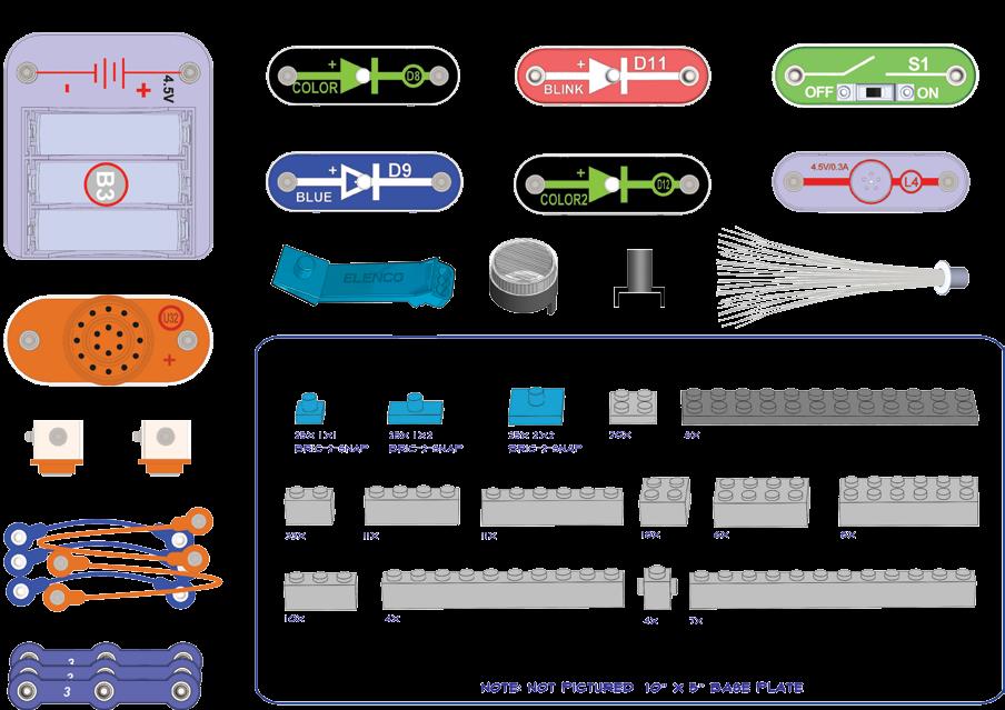
3 Parts List (Colors and styles may vary) Symbols and Numbers Important: If any parts are missing or damaged, DO NOT RETURN TO RETAILER. Call toll-free (800) or us at: Customer Service: 150 Carpenter Ave., Wheeling, IL U.S.A. You may order additional / replacement parts at Qty. ID Name Symbol Part # r 4 Brick 1x1, 3-Sided 6BR1X1S3 r 33 Brick 1x2 6BR1X2G r 10 Brick 1x3 6BR1X3G Qty. ID Name Symbol Part # r 1 Brick Remover Tool 6BRTOOL r Snap Wire 6SC03 r 2 3D Snap 6SC3DSNAP r 11 Brick 1x4 6BR1X4G r 1 B3 Battery Holder - uses three (3) 1.5V type AA (not Included) 6SCB3 r 11 Brick 1x6 6BR1X6G r 4 Brick 1x10 6BR1X10G r 7 Brick 1x12 6BR1X12G r 18 Brick 2 6BR2X2G r 6 Brick 4 6BR2X4G r 8 Brick 6 6BR2X6G r 25 Bric2snap Adapter, 1x1 6BRA1X1 r 25 Bric2snap Adapter, 1x2 6BRA1X2 r 25 Bric2snap Adapter, 2 6BRA2X2 r 1 Baseplate 10 x 5 6BRBP1 r 6 Plate 12 6BRP2X12DG r 20 Plate 2 6BRP2X2G r 1 D8 Color LED 6SCD8 r 1 D9 Blue LED 6SCD9 r 1 D11 Blink Red LED 6SCD11 r 1 D12 Color2 LED 6SCD12 r 1 Fiber Optic Tree 6SCFT r 1 Mounting Base 6SCFMB r 2 Jumper Wire (Orange) 6SCJ3A r 3 Jumper Wire (Blue) 6SCJ4 r 1 L4 4.5V Lamp 6SCL4 r 1 Lined Lens LED Attachment 6SCLLENS r 1 S1 Slide Switch 6SCS1 r 1 U32 Melody IC 6SCU32 2


 1.5V AA batteries (not included).")

4 Snap Circuits uses building blocks with snaps to build the different electrical and electronic circuits in the projects. Each block has a function: there are switch blocks, light blocks, battery blocks, different length wire blocks, etc. These blocks are different colors and have numbers and letters on them so that you can easily identify them. The blocks you will be using are shown as color symbols, allowing you to easily snap them together to form a circuit. How to Use Snap Circuits When installing a battery, be sure the spring is compressed straight back, and not bent up, down, or to one side. Sometimes if can be difficult to separate bric2snap adapters from the baseplate or bricks and plates, so use the Brick Remover Tool for help for needed, as shown: For Example: This is the slide switch, it is green and has the marking S1 on it. The part symbols in this booklet may not exactly match the appearance of the actual parts, but will clearly identify them. Some circuits use the jumper wires to make unusual connections. Just clip them on as indicated. You can also use the remover to separate bricks and plates from each other. You need a power source to build each circuit. This is labeled B3 and requires three (3) 1.5V AA batteries (not included). Often you will mount Snap Circuits components on bric2snap adapters, simply place them on the posts of the adapters: Note that this set includes 25 of each of the bric2snap adapter pieces, more are used in projects in this booklet. Your set includes extra adapters so you can easily expand on your own using other Snap Circuits and bricks sets you may have. Note: While building the projects, be careful not to accidentally make a direct connection across the battery holder (a short circuit ), as this may damage and/or quickly drain the batteries. 3

 are wires used to connect components.")

 electricity flows if the voltage exceeds a turn-on threshold brightness then increases.")


5 BATTERY HOLDER The batteries (B3) produce an electrical voltage using a chemical reaction. This voltage can be thought of as electrical pressure, pushing electricity through a circuit just like a pump pushes water through pipes. This voltage is much lower and much safer than that used in your house wiring. Using more batteries increases the pressure, therefore, more electricity flows. About Your Snap Circuits Parts SNAP WIRES & JUMPER WIRES The blue 3-snap wires and jumper wires (blue & orange) are wires used to connect components. They are used to transport electricity and do not affect circuit performance. The 3-snap wires make rigid connections, while the jumper wires make flexible connections. Wires transport electricity just like pipes are used to transport water. The colorful plastic coating protects them and prevents electricity from getting in or out. LEDs The color, blue, blink red, and color2 LEDs (D8, D9, D11 & D12) are light emitting diodes, and may be thought of as a special one-way light bulbs. In the forward direction, (indicated by the arrow in the symbol) electricity flows if the voltage exceeds a turn-on threshold brightness then increases. The blink red LED contains a microcircuit that turns it on and off. The color and color2 LEDs contain red, green, and blue LEDs, with a micro-circuit controlling them. A high current will burn out an LED, so the current must be limited by other components in the circuit (Snap Circuits LEDs have internal resistors added, to protect them in case you make wiring mistakes). LEDs block electricity in the reverse direction. Battery Holder (B3) SLIDE SWITCH The slide switch (S1) connects ( ON ) or disconnects ( OFF ) the wires in a circuit. When ON it has no effect on circuit performance. Switches turn on electricity just like a faucet turns on water from a pipe. SOUND MODULE The melody IC (U32) contains a specialized sound-generation integrated circuit (IC), a small speaker, and a few supporting components. The IC has a recording of the melody, which it makes into an electrical signal for the speaker. The speaker converts the signal into mechanical vibrations. The vibrations create variations in air pressure, which travel across the room. You hear sound when your ears feel these air pressure variations. LAMP A light bulb, such as in the 4.5V lamp (L4), contains a special thin high-resistance wire. When a lot of electricity flows through, this wire gets so hot it glows bright. Voltages above the bulb s rating can burn out the wire. (Part designs are subject to change without notice). 4
 through a material due to electrical pressure across the material, such as from a battery.")


6 What is electricity? Nobody really knows. We only know how to produce it, understand its properties, and how to control it. Electricity is the movement of sub-atomic charged particles (called electrons) through a material due to electrical pressure across the material, such as from a battery. Power sources, such as batteries, push electricity through a circuit, like a pump pushes water through pipes. Wires carry electricity, like pipes carry water. Devices like LEDs, motors, and speakers use the energy in electricity to do things. Switches and transistors control the flow of electricity like valves and faucets control water. Resistors limit the flow of electricity. The electrical pressure exerted by a battery or other power source is called voltage and is measured in volts (V). Notice the + and signs on the battery; these indicate which direction the battery will pump the electricity. Introduction to Electricity machinery and appliances. The most important aspect of electricity in our society is that it allows energy to be easily transported over distances. Note that distances includes not just large distances but also tiny distances. Try to imagine a plumbing structure of the same complexity as the circuitry inside a portable radio - it would have to be large because we can t make water pipes so small. Electricity allows complex designs to be made very small. There are two ways of arranging parts in a circuit, in series or in parallel. Here are examples: The electric current is a measure of how fast electricity is flowing in a wire, just as the water current describes how fast water is flowing in a pipe. It is expressed in amperes (A) or milliamps (ma, 1/1000 of an ampere). Series Circuit The power of electricity is a measure of how fast energy is moving through a wire. It is a combination of the voltage and current (Power = Voltage x Current). It is expressed in watts (W). The resistance of a component or circuit represents how much it resists the electrical pressure (voltage) and limits the flow of electric current. The relationship is Voltage = Current x Resistance. When the resistance increases, less current flows. Resistance is measured in ohms (Ω), or kilo ohms (kω, 1000 ohms). Nearly all of the electricity used in our world is produced at enormous generators driven by steam or water pressure. Wires are used to efficiently transport this energy to homes and businesses where it is used. Motors convert the electricity back into mechanical form to drive Parallel Circuit Placing components in series increases the resistance; highest value dominates. Placing components in parallel decreases the resistance; lowest value dominates. The parts within these series and parallel sub-circuits may be arranged in different ways without changing what the circuit does. Large circuits are made of combinations of smaller series and parallel circuits. 5

, and wiring paths between them and back.")

.")
7 DOs and DON Ts of Building Circuits After building the circuits given in this booklet, you may wish to experiment on your own. Use the projects in this booklet as a guide, as many important design concepts are introduced throughout them. Every circuit will include a power source (the batteries), a resistance (which might be a lamp, melody IC, or LED (which has an internal protection resistor), etc.), and wiring paths between them and back. You must be careful not to create short circuits (very low-resistance paths across the batteries, see examples below) as this will damage components and/or quickly drain your batteries. Elenco is not responsible for parts damaged due to incorrect wiring. If you are only using the parts in this set, then your parts cannot be damaged by incorrect wiring. Here are some important guidelines: ALWAYS USE EYE PROTECTION WHEN EXPERIMENTING ON YOUR OWN. ALWAYS include at least one component that will limit the current through a circuit, such as a lamp, melody IC, or an LED (which has an internal protection resistor). ALWAYS use switches in conjunction with other components that will limit the current through them. Failure to do so will create a short circuit and/or damage those parts. ALWAYS disconnect your batteries immediately and check your wiring if something appears to be getting hot. ALWAYS check your wiring before turning on a circuit. NEVER connect to an electrical outlet in your home in any way. NEVER leave a circuit unattended when it is turned on. For all of the projects given in this book, the parts may be arranged in different ways without changing the circuit. For example, the order of parts connected in series or in parallel does not matter what matters is how combinations of these sub-circuits are arranged together. Note that this set includes 25 of each of the bric2snap adapter pieces, though no more than 10 are used in projects in this booklet. Your set includes extra adapters so you can easily expand on your own using other Snap Circuits and bricks sets you may have. Placing a 3-snap wire directly across the batteries is a SHORT CIRCUIT.! NEVER DO! This is also a SHORT CIRCUIT. When the slide switch (S1) is turned on, this large circuit has a SHORT CIRCUIT path (as shown by the arrows). The short circuit prevents any other portions of the circuit from ever working.! Examples of SHORT CIRCUITS - NEVER DO THESE!!!! NEVER DO!! NEVER DO! NEVER DO! Warning to Snap Circuits owners: Do not connect additional voltage sources from other sets, or you may damage your parts. Contact ELENCO if you have questions or need guidance. You are encouraged to tell us about new circuits and structures you create. If they are unique, we will post them with your name and state on our website at: elenco.com/showcase Send your suggestions (with photos) to ELENCO : info@elenco.com WARNING: SHOCK HAZARD - Never connect Snap Circuits to the electrical outlets in your home in any way!! 6
8 Advanced Troubleshooting (Adult supervision recommended) Elenco is not responsible for parts damaged due to incorrect wiring. If you suspect you have damaged parts, you can follow this procedure to systematically determine which ones need replacing: 1. Lamp (L4), color LED (D8), blue LED (D9), blink red LED (D11), color2 LED (D12), melody IC (U32), and battery holder (B3): Place batteries in holder. Place the lamp directly across the battery holder, it should light. Place the LEDs (D8, D9, D11, & D12) directly across the battery holder one at a time (LED + to battery +), the LED should light (D8 should change colors, D11 should be blinking, and D12 should slowly change colors). Place the melody IC directly across the battery holder (+ to +), it should play a tune. If none work, then replace your batteries and repeat, if still bad then the battery holder is damaged. 3. Jumper wires (blue and orange): Use this mini-circuit to test each jumper wire, the lamp should light snap wires: Use this mini-circuit to test each of the 3-snap wires. The lamp should light. 6. Slide switch (S1): Build this mini-circuit; if the lamp doesn t light then the slide switch is bad. You may order additional / replacement parts at: Phone: (847) help@elenco.com Project Listings Project Description Page 1 Start Circuit Lights and a Melody Lights and Clicking 12 4 Light Post Directional Lights 15 6 Cross of Lights Bric Tower Bric Bridge House of Lights Bric Mammal Leds in Series & Parallel Bric Building Tri-Level House Elevated Circuit Bi-Level Circuit Overhead Light Shine Out Light House Four Fun Four Further Fun Bric Elevation Bric House Diagonal Circuit Wall of Lights Your Wall of Lights Story House

, and architects make drawings for their building (called prints or")


9 SCHEMATICS AND BLUE PRINTS After building the structures in this set, you may want to expand using parts from other brick construction and Snap Circuits sets you already have. For this, advance planning is recommended. Think about what you want your structure to do and how you want it to look before you start building it. Electrical engineers make drawings of their circuits (called schematics), and architects make drawings for their building (called prints or floor plans). Schematics and prints are also useful in analyzing problems or making changes after the circuit or structure has been built. Electrical schematics use simple symbols to represent the electrical components, often the same symbols that are marked on your Snap Circuits components. Wires are represented by just lines and can be of any length. This is a schematic for the circuit in project 11: This is a schematic for the circuit in projects 2, 7, 8, 12, 13, and TBD; although those circuits are all constructed differently, electrically they are the same, with D8, D9, D11, D12, L4, and U32 all connected in parallel: Schematics tell you how a circuit will work, but not how it is constructed. Similarly an architect s print or floor plan of a house tells you about the layout of the house, but not colors or other details. Here is an example of a floor plan drawing for a house: An architect s drawings may show the floor plan or other information about the construction, depending on who will be using the drawing. These drawings used to be call blueprints, due to the color used when making them years ago. Notice that the symbol for a switch in electrical schematics is based on the architect s symbol for a door. 8


 and color LED (D8) on the other parts, as shown.")
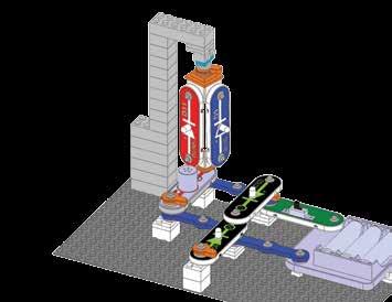
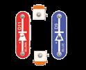
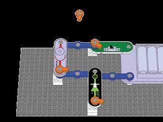
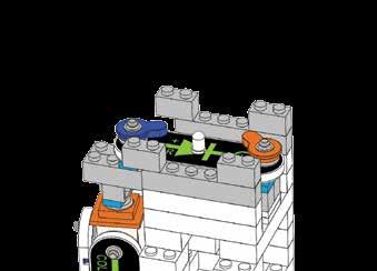
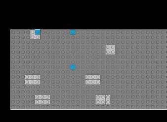
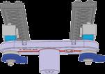
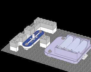
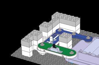
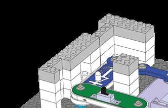
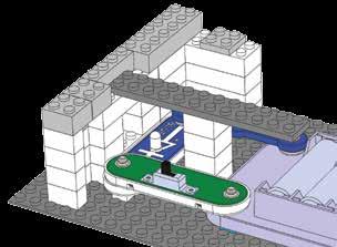
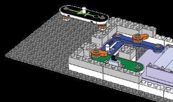
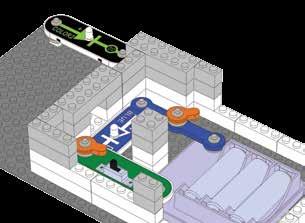
10 Project 1 START CIRCUIT NOTE: this circuit (and many others in this book) have an LED being used without a resistor or other component to limit the electric current through it. Normally this could damage an LED but your Snap Circuits LEDs include internal protection resistors, & will not be damaged. Be careful if you later use other electrical sets with unprotected LEDs. T he festive tree and egg may also be used with other Snap Circuits LEDs from different sets. Snap Circuits uses electronic blocks that snap onto pegs to build different circuits. These blocks have different colors and numbers on them so you can easily identify them. Place 4 bric2snap adapters and one 2 plate on the baseplate as shown. Then mount the 3-snap wire and battery holder (B3) on the adapters. Next, place the slide switch (S1) and color LED (D8) on the other parts, as shown. Install three (3) AA batteries (not included) into the battery holder (B3) if you have not done so already; be sure the battery springs are compressed straight back, and not bent up, down, or to one side. 9
.")
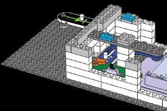
11 Project 1 START CIRCUIT Turn on the slide switch, and enjoy the light show from the color LED (D8). For best effects, place the fiber optic tree on the color LED using the mounting base, and dim the room lights. Variants: A. Replace the color LED with the color2 LED (D12). The color2 LED changes colors more slowly. B. Replace the color2 LED with the blue LED (D9). C. Replace the blue LED (D9) with the blink red LED (D11). D. Replace the blink red LED (D11) with the lamp (L4). E. Replace the lamp (L4) with the melody IC (U32, + on left). Snappy says when you turn on the slide switch, electricity flows from the batteries, through the color LED and back to the battery through the switch. If the switch is off, the flow of electricity is blocked, and the color LED won t light. LEDs are light emitting diodes, which convert electrical energy into light. The color of the light depends on the characteristics of the material used in them. The color LED actually contains separate red, green, and blue lights, with a micro-circuit controlling them; the colors can be combined to produce yellow, cyan, purple, and white. 1o

.")
. The lamp (L4) and 4 LEDs (D8, D9, D11, & D12) light,")

12 Project 2 5 Lights and a Melody 1 2 1ox 2X 3 4 All the lights and the melody IC are connected in parallel, so swapping their locations won t change the circuit (but don t connect them backwards or they won t work). Build the circuit as shown, and turn on the slide switch (S1). The lamp (L4) and 4 LEDs (D8, D9, D11, & D12) light, and the melody IC (U32) plays. For best effects, place the fiber optic tree on one of the LEDs using the mounting base, and dim the room lights. 11
, blink red LED (D11), and lamp (L4)")
.")


13 Project 3 4 Lights and Clicking 1 2 8x 7x 3 4 This circuit has the melody IC (U32), blink red LED (D11), and lamp (L4) connected in series, to show the differences in how they operate. Build the circuit as shown, and turn on the slide switch (S1). The four LEDS (D8, D9, D11, & D12) should be on, the lamp (L4) should be off, and there may be a slight clicking from the melody IC (U32). For best effects, place the fiber optic tree on one of the LEDs using the mounting base, and dim the room lights. Next, add a jumper wire at one of these locations: A. Across U32: the sound stops and D11 is brighter. B. Across D11: D11 is off, and U32 plays a tune. C. Across U32 and D11: L4 is on. Use the remover tool to help separate the bricks and adapters when dismantling the circuit. 12


14 Project 4 Light Post 1 2 7x 7x 3X 3 4 9x 5 6 LINED LENS 13
. The four LEDs (D8, D9, D11, & D12) and lamp (L4) light.")

,")
15 Project 4 Light post Build the circuit as shown, and turn on the slide switch (S1). The four LEDs (D8, D9, D11, & D12) and lamp (L4) light. The 3D snaps allow the blue and blink red LEDs to be rotated to shine in any direction. For best effects, place the fiber optic tree on the color2 LED (D12) using the mounting base, place the lined lens on the color LED (D8), and dim the room lights. You can swap LED locations as desired. 14


. The LEDs")


16 Project 5 Directional Lights Build the circuit as shown, and turn on the slide switch (S1). The LEDs (D9 &D11) light, and can be rotated to shine in any direction. You can replace the LEDs with any of the other ones


17 Project 6 Cross of Lights 1 2 Back View x Back View
. Four LEDs and a lamp light.")
18 Project 6 Cross of Lights Build the circuit as shown, and turn on the slide switch (S1). Four LEDs and a lamp light. 17


")
. 6")
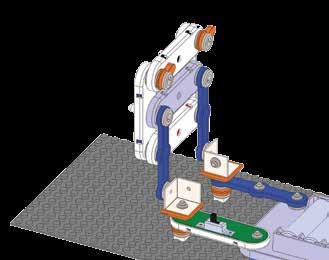
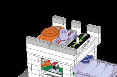
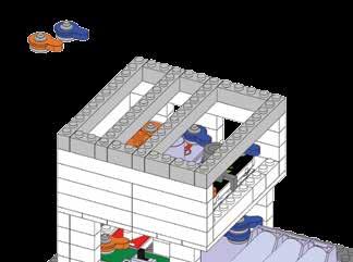
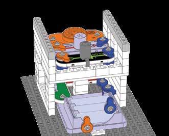
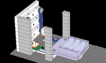
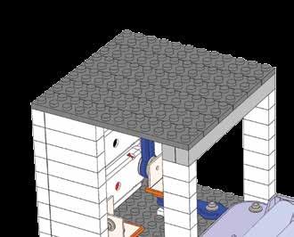
19 Project 7 BRIC Tower x 5x 5 Note: You can omit the sound by removing the melody IC (move the blink red LED (D11) to where the melody IC was). 6 18


20 Project 7 BRIC Tower o Add 2 wires, one end loose: ox 1ox 19


21 Project 7 BRIC Tower x 2o
.")
 light, and the melody IC (U32)")


22 Project 7 BRIC Tower Build the circuit as shown, and turn on the slide switch (S1). The four LEDs (D8, D9, D11, & D12) and lamp (L4) light, and the melody IC (U32) plays tunes. The 3D snaps allow the blue and blink red LEDs to be rotated to shine in different directions. Dim the room lights for best effects. You can omit the sound by removing the melody IC (move the blink red LED (D11) to where the melody IC was). 21


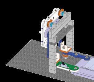
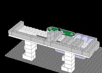
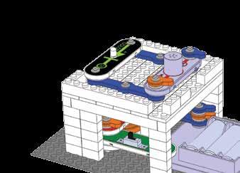
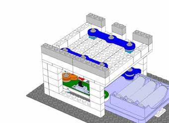
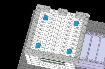
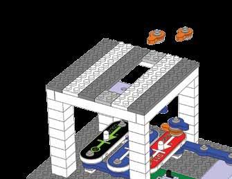
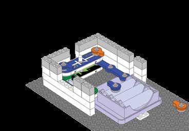
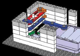
23 Project 8 BRIC Bridge 1 2 1x 3 4 x6 5 6 Note: if one of the blue jumper wires is a tight fit, then use an orange one instead. 8x 22


24 Project 8 BRIC Bridge LINED LENS, orient like this o
.")
 plays tunes.")

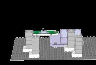
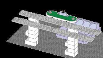
25 Project 8 BRIC Bridge 13 Build the circuit as shown, and turn on the slide switch (S1). The four LEDs (D8, D9, D11, & D12) and lamp (L4) light, and the melody IC (U32) plays tunes. The 3D snaps allow the blue and blink red LEDs to be rotated to shine in different directions. Dim the room lights for best effects. You can omit the sound by removing the melody IC (move the color LED (D8) to where the melody IC was). 24

.")
 and lamp")


26 Project 9 House of Lights Build the circuit as shown, and turn on the slide switch (S1). The four LEDs (D8, D9, D11, & D12) and lamp (L4) light. The 3D snaps allow the blue and color2 LEDs to be rotated to shine in different directions. Dim the room lights for best effects x 25 5x


 with")


.")


27 Project 9 House of Lights You can add sound by replacing the lamp (L4) with the melody IC ( + side should be away from the S1 switch). You can also change the locations of the LEDs and lamp with each other o 8x 11 26


28 Project 10 BRIC Mammal x 27


 light.")


29 Project 10 BRIC Mammal x 1o 7x Build the circuit as shown, and turn on the slide switch (S1). The LEDs (D11, & D12) light. If you look straight at the structure it resembles a mammal, with eyes that light up. You can adjust the position of the wires so they are less visible. You can replace the LEDs with different ones if desired. 28
 light; watch how their patterns change.")


30 Project 11 1 LEDs in Series & Parallel 2 Build the circuit as shown, and turn on the slide switch (S1). The LEDs (D8, D11, & D12) light; watch how their patterns change. Try swapping the LED locations and replacing one with the blue LED (D9),; try all combinations and see how the effects change. You can also place the unused 3-snap wire where the color2 LED is and see how the circuit changes. Here the color LED and blink red LED are connected in parallel, and then connected in series with the color2 LED, to produce some interesting effects. The electricity from the batteries flows through the color2 LED, then splits up between the color and blink red LEDs, then recombines in the switch before returning to the batteries. When LEDs are connected in series the battery voltage may not be strong enough to fully turn them on. Red light is easier to produce then the other colors, and so turns on more easily. 29


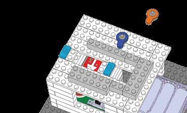
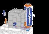
31 Project 12 BRIC Building o


 and lamp")
 plays tunes.")


32 Project 12 BRIC Building 7 8 1ox 1ox 1ox 1ox 9 Build the circuit as shown, and turn on the slide switch (S1). The four LEDs (D8, D9, D11, & D12) and lamp (L4) light, and the melody IC (U32) plays tunes. The 3D snaps allow the blue and color2 LEDs to be rotated to shine in different directions. Dim the room lights for best effects. You can remove the melody IC if desired, just shift the blink red LED (D11) to where the melody IC was. 31


33 Project 13 Tri-Level House ox 4 8x 5 6 5x 32


34 Project 13 Tri-Level House o x 33
.")
 plays tunes.")

35 Project 13 Tri-Level House Build the circuit as shown, and turn on the slide switch (S1). The four LEDs (D8, D9, D11, & D12) and lamp (L4) light, and the melody IC (U32) plays tunes. The 3D snaps allow the blue and color2 LEDs to be rotated to shine in different directions. Dim the room lights for best effects. You can remove the melody IC or re-arrange any of the lights if desired. 34


. The LEDs (D8 &")
")


36 Project 14 Elevated Circuit 1 2 1ox Build the circuit as shown, and turn on the slide switch (S1). The LEDs (D8 & D9) light, and the melody IC (U32) plays tunes. You can replace the LEDs and melody IC with any of the other lights. 2 1ox 18x 35

 light in a blinking")

 turns on and off,")

37 Project 15 Bi-Level Circuit 1 2 5x 1ox 1 3 Build the circuit as shown, and turn on the slide switch (S1). The LEDs (D11 & D12) light in a blinking pattern. You can replace the LEDs with any other LEDs and see how the circuit changes. As the blink red LED (D11) turns on and off, the brightness of the color2 LED (D12) also changes because those LEDs are connected in series. When components are connected in series, a change in one affects the others. 36


38 Project 16 Overhead Light Top View
.")

39 Project 16 Overhead Light 7 Build the circuit as shown, and turn on the slide switch (S1). The four LEDs (D8, D9, D11, & D12) and lamp (L4) light. Dim the room lights for best effects. You can re-arrange the lights as desired, or replace one with the melody IC (U32). 38


40 Project 17 3 Shine Out 1 2 7x 21x 1ox 5x 3 4 Back View
41 Project 17 3 Shine Out Build the circuit as shown, and turn on the slide switch (S1). The three LEDs (D8, D11, & D12) light. You can re-arrange the LEDs or replace one with the blue LED (D9). 4o


42 Project 18 Light House x 5x 5 6 5x 41


.")

 light.")


43 Project 18 Light House Build the circuit as shown, and turn on the slide switch (S1). The blue and color2 LEDs (D9 & D12) light. You can replace the LEDs with any of the other lights o 5x 11 42

.")


44 Project 19 Four Fun 1 2 8x 3 This circuit has two pairs of parallel LEDs in series with each other. Some of the LEDs are blinking in different patterns (D11 turning on and off, D8 changing colors quickly, and D12 changing colors slowly). Red color is easier to produce than green or blue, and green is easier to produce than blue. The combination of these effects creates the pattern you see. 43 Build the circuit as shown, and turn on the slide switch (S1). The four LEDs light in a blinking pattern, but some will be dim. You can swap the LEDs with each other and see how the circuit changes. You can also remove one LED, or replace one with the melody IC (U32).
 light in a dim blinking pattern, and the melody IC (U32) makes weird sounds Try removing one of the LEDs at")

45 Project 20 Four Further fun Build the circuit as shown, and turn on the slide switch (S1). The three LEDs (D8, D11, & D12) light in a dim blinking pattern, and the melody IC (U32) makes weird sounds Try removing one of the LEDs at a time and see how the sound changes. Electricity from the batteries goes through the melody IC, then splits up and goes through the three LEDs, then re-combines in the switch. The LEDs all having different blinking patterns and the melody IC has a sound pattern; their combination creates the effects you see and hear. 44


46 Project 21 BRIC Elevation X 45


. The")

 light.")


47 Project 21 BRIC Elevation Build the circuit as shown, and turn on the slide switch (S1). The blue and color2 LEDs (D9 & D12) light. You can replace the LEDs with any of the other lights o 11 46


48 Project 22 Bric House 1 2 9x


49 Project 22 Bric House o

50 Project 22 Bric House 13 5x 49

. The three LEDs (D8, D9, &")
")
 is used here as a")

51 Project 23 diagonal Circuit Build the circuit as shown, and turn on the slide switch (S1). The three LEDs (D8, D9, & D11) light in a dim blinking pattern, and the melody IC (U32) makes weird sounds. The lamp (L4) is used here as a 3-snap wire and does not light. Try replacing one of the LEDs with the color2 LED (D12). 5o

 shines a colorful pattern on")

 makes sound, and can be")
 with the")
52 Project 24 Wall of Light 1 2 8x 1 1ox 3 4 LINED LENS, orient like this Build the circuit as shown, and turn on the slide switch (S1). The color LED (D8) shines a colorful pattern on the wall of bricks, for best effects rotate the lined lens so its lines converge toward the wall, and place the circuit in a dark room. The melody IC (U32) makes sound, and can be removed from the circuit if desired. You can replace the color LED (D8) with the color2 LED (D12) to change the effects. 51


 to change the")
53 Project 25 Your Wall of Light 1 2 Place this circuit close to a wall in a dark room. For best effects rotate the lined lens so its lines converge toward the wall. You can replace the color LED (D8) with the color2 LED (D12) to change the effects. 52


54 Project 26 2 Story House 1 2 5x 3 4 8x


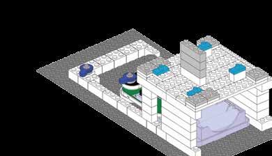
55 Project 26 2 Story House x 9 1O 1 1 This structure is shown on the cover of your box, use that picture as a guide in building it. 54


56 Project 26 2 Story House What s next? Your set includes more brick-to-snap adapters than are needed to build the structures in this book, so that you may expand on your own using parts from other Snap Circuits and bricks sets you may have. 55
57 Notes:
58 Notes:


59 SNAP CIRCUITS BEGINNER Model SCB-20 Begin your Snap Circuits Experience with a wonderful introduction to problem solving, following directions and the satisfaction of a job well done. Includes 14 parts build over 20 projects. Extra safety features for younger engineers, 5 and up. Easy-to-follow color manual diagrammed like no other Snap Circuits Kit. Other Snap Circuits Products! For a listing of local toy retailers who carry Snap Circuits visit elenco.com or call us toll-free at For Snap Circuits accessories or additional parts visit elenco.com. SNAPINO Model SC-SNAPINO Snapino is an introduction to the open source Arduino Hardware software environment. Learn to code and utilize your Snap Circuits modules at the same time! A great introduction to coding and the Arduino platform Arduino is a microcontroller used in robotics and other applications Includes over 15 parts build over 20 projects. SNAP CIRCUITS 3D MEG Model SC-3DMEG SNAP CIRCUITS 3D-MEG uses building pieces with snaps to make realistic, 3-D circuits, like those found in homes, electronic equipment and skyscrapers. SNAP CIRCUITS Kids can build their own house with roof lights and ceiling fans while finding out how all the electric and mechanical functions work! Contains unique stabilizers for building amazing 3D structures. Kids love making their circuit inventions into 3D! SNAP CIRCUITS 3D ILLUMINATION Model SC-3Di SNAP CIRCUITS 3D Illumination uses building blocks with snaps to build the different electrical and electronic circuits in the projects. Each block has a function: there are switch blocks, light blocks, battery blocks, different length wire blocks, etc. 3-Color Light Tunnel, Mirrors & Reflecting Circuits Projector With 6 Images SNAP CIRCUITS ARCADE Model SCA-200 Snap Circuits Arcade is an exciting introduction to problem solving, following directions and the satisfaction of a job well done. 30 Snap Modules included More than 200 projects Enjoy completing projects using a programmable Word Fan, Dual LED Display and a pre-programmed microcontroller. SNAP CIRCUITS LIGHT Model SCL-175 Contains over 55 parts. Build over 175 exciting projects. Color organ controlled by smartphone, voice or finger. Enjoy your music as the lights change to the beat. Snap-together parts require no tools and ensure correct connections. Clear and concise illustrated manual included & available online SNAP CIRCUITS JR Model SC-100 Over 30 parts and over 100 projects SNAP CIRCUITS MOTION Model SCM-165 Over 50 parts and over 165 projects SNAP CIRCUITS Model SC-300 Over 60 parts and over 300 projects SNAP CIRCUITS EXTREME Model SC-750 Over 80 parts and over 750 projects Smart-phone shown not included.


60 SC-BRIC1 Parts Layout Note: A complete list is on pages 2 in this manual. Not responsible for typographical errors. 150 CARPENTER AVE. WHEELING, IL USA ELENCO.COM Important: If parts are missing or damaged, DO NOT RETURN TO RETAILER. Call (800) or help@elenco.com.
8 PIN PIC PROGRAMMABLE BOARD (DEVELOPMENT BOARD & PROJECT BOARD)
") ESSENTIAL INFORMATION BUILD INSTRUCTIONS CHECKING YOUR PCB & FAULT-FINDING MECHANICAL DETAILS HOW THE KIT WORKS LEARN ABOUT PROGRAMMING WITH THIS 8 PIN PIC PROGRAMMABLE BOARD (DEVELOPMENT BOARD & PROJECT
ESSENTIAL INFORMATION BUILD INSTRUCTIONS CHECKING YOUR PCB & FAULT-FINDING MECHANICAL DETAILS HOW THE KIT WORKS LEARN ABOUT PROGRAMMING WITH THIS 8 PIN PIC PROGRAMMABLE BOARD (DEVELOPMENT BOARD & PROJECT
ELECTRONIC GAME KIT TEACHING RESOURCES. Version 2.0 BUILD YOUR OWN MEMORY & REACTIONS
 TEACHING RESOURCES SCHEMES OF WORK DEVELOPING A SPECIFICATION COMPONENT FACTSHEETS HOW TO SOLDER GUIDE BUILD YOUR OWN MEMORY & REACTIONS ELECTRONIC GAME KIT Version 2.0 Index of Sheets TEACHING RESOURCES
Service Call: Fiber Optic Installation and Repair
 Service Call: Fiber Optic Installation and Repair Tools Required: Tools available from www.bohlinger.biz Cable: Terex P/N 453830 Stripper Block: P/N 65-020-01 Termination Block: P/N 65-020-02 Utility Knife
COLOUR CHANGING USB LAMP KIT
 TEACHING RESOURCES SCHEMES OF WORK DEVELOPING A SPECIFICATION COMPONENT FACTSHEETS HOW TO SOLDER GUIDE SEE AMAZING LIGHTING EFFECTS WITH THIS COLOUR CHANGING USB LAMP KIT Version 2.1 Index of Sheets TEACHING
ALO 030 MKII. 30 Watt DMX LED scanner. User manual
 ALO 030 MKII 30 Watt DMX LED scanner User manual Safety instructions WARNING! Always keep this device away from moisture and rain! Hazardous electrical shocks may occur! WARNING! Only connect this device
Lesson Sequence: S4A (Scratch for Arduino)
") Lesson Sequence: S4A (Scratch for Arduino) Rationale: STE(A)M education (STEM with the added Arts element) brings together strands of curriculum with a logical integration. The inclusion of CODING in STE(A)M
Lesson Sequence: S4A (Scratch for Arduino) Rationale: STE(A)M education (STEM with the added Arts element) brings together strands of curriculum with a logical integration. The inclusion of CODING in STE(A)M
QUIZ BUZZER KIT TEACHING RESOURCES. Version 2.0 WHO ANSWERED FIRST? FIND OUT WITH THIS
 TEACHING RESOURCES SCHEMES OF WORK DEVELOPING A SPECIFICATION COMPONENT FACTSHEETS HOW TO SOLDER GUIDE WHO ANSWERED FIRST? FIND OUT WITH THIS QUIZ BUZZER KIT Version 2.0 Index of Sheets TEACHING RESOURCES
Introduction 1. Green status LED, controlled by output signal ST. Sounder, controlled by output signal Q6. Push switch on input D6
 Introduction 1 Welcome to the GENIE microcontroller system! The activity kit allows you to experiment with a wide variety of inputs and outputs... so why not try reading sensors, controlling lights or
7 SEGMENT LED DISPLAY KIT
 ESSENTIAL INFORMATION BUILD INSTRUCTIONS CHECKING YOUR PCB & FAULT-FINDING MECHANICAL DETAILS HOW THE KIT WORKS CREATE YOUR OWN SCORE BOARD WITH THIS 7 SEGMENT LED DISPLAY KIT Version 2.0 Which pages of
Trusted 40 Channel Analogue Input FTA
 PD-T8830 Trusted Trusted 40 Channel Analogue Input FTA Product Overview The Trusted 40 Channel Analogue Input Field Termination Assembly (FTA) T8830 is designed to act as the main interface between a field
JunoScan MK-II LED scanner. user manual
 JunoScan MK-II LED scanner user manual Musikhaus Thomann e.k. Treppendorf 30 96138 Burgebrach Germany Telephone: +49 (0) 9546 9223-0 E-mail: info@thomann.de Internet: www.thomann.de 26.10.2012 Table of
Tube Cricket Build Guide
 Tube Cricket Build Guide The Tube Cricket is a small-wattage amp that puts out about 1 watt of audio power. With a 12AU7 tube-preamp and a JRC386 power amp, the Tube Cricket gives you great tone in a compact
( InfoSystems Translation )
") IN THE UNITED STATES DISTRICT COURT FOR THE WESTERN DISTRICT OF TEXAS WACO DIVISION RETROLED COMPONENTS, LLC, Plaintiff, v. PRINCIPAL LIGHTING GROUP, LLC Defendant. Civil Case No. 6:18-cv-55-ADA JURY TRIAL
IN THE UNITED STATES DISTRICT COURT FOR THE WESTERN DISTRICT OF TEXAS WACO DIVISION RETROLED COMPONENTS, LLC, Plaintiff, v. PRINCIPAL LIGHTING GROUP, LLC Defendant. Civil Case No. 6:18-cv-55-ADA JURY TRIAL
AXE101 PICAXE-08M2 Cyberpet Kit
 AXE101 PICAXE-08M2 Cyberpet Kit The Cyberpet project uses a PICAXE-08M2 microcontroller with two LEDs as the pets eyes and a piezo sounder as a voice for the pet. The project also uses a switch so that
Light Emitting Diodes (LEDs)
") Light Emitting Diodes (LEDs) Example: Circuit symbol: Function LEDs emit light when an electric current passes through them. Connecting and soldering LEDs must be connected the correct way round, the diagram
Light Emitting Diodes (LEDs) Example: Circuit symbol: Function LEDs emit light when an electric current passes through them. Connecting and soldering LEDs must be connected the correct way round, the diagram
Practical Exercise Look at the circuit diagram shown. What will happen in this circuit if switch S2 is pressed momentarily?
 Practical Exercise 3 1. Two electronics technicians are discussing the resistance of copper wire. Technician A says that the resistance of copper wire increases as its cross-sectional area increases. Technician
STX Stairs lighting controller.
 Stairs lighting controller STX-1795 The STX-1795 controller serves for a dynamic control of the lighting of stairs. The lighting is switched on for consecutive steps, upwards or downwards, depending on
User s Manual. Smart Shots Sports Center VTech Printed in China US
 User s Manual Smart Shots Sports Center 2014 VTech Printed in China 91-002920-006 US INTRODUCTION Thank you for purchasing the VTech Smart Shots Sports Center! Cheer on your little sports star with the
Safety Information. Camera System. If you back up while looking only at the monitor, you may cause damage or injury. Always back up slowly.
 Table of Contents Introduction...3 Safety Information...4-6 Before Beginning Installation...7 Installation Guide...8 Wiring Camera & Monitor...9-10 Replacement Installation Diagram...11 Clip-On Installation
Part names (continued) Remote control
 Remote control") Introduction Part names (continued) Remote control (1) STANDBY ( 25) (1) (2) ON ( 25) (3) (3) ID - 1 / 2 / 3 / 4 s ( 18) (4) (4) COMPUTER 1 ( 27) (7) (5) COMPUTER 2 * (8) (6) COMPUTER 3 * (10) (13) (7)
Introduction Part names (continued) Remote control (1) STANDBY ( 25) (1) (2) ON ( 25) (3) (3) ID - 1 / 2 / 3 / 4 s ( 18) (4) (4) COMPUTER 1 ( 27) (7) (5) COMPUTER 2 * (8) (6) COMPUTER 3 * (10) (13) (7)
Bill of Materials: Super Simple Water Level Control PART NO
 Super Simple Water Level Control PART NO. 2169109 Design a simple water controller in which electrodes are required to sense high and low water levels in a tank. Whenever the water level falls below the
Prototyping & Engineering Electronics Kits Magic Mandala Kit Guide
 Prototyping & Engineering Electronics Kits Magic Mandala Kit Guide odysseyboard.com Please refer to www.odysseyboard.com for a PDF updated version of this guide. Magic Mandala Guide version 1.0, February,
apple Service Source Apple Studio Display 17" LCD (ADC) Updated 6 Decenber Apple Computer, Inc. All rights reserved.
 Updated 6 Decenber Apple Computer, Inc. All rights reserved.") apple Service Source Apple Studio Display 17" LCD (ADC) Updated 6 Decenber 2004 2003 Apple Computer, Inc. All rights reserved. apple Service Source Take Apart Apple Studio Display 17" LCD (ADC) 2003 Apple
apple Service Source Apple Studio Display 17" LCD (ADC) Updated 6 Decenber 2004 2003 Apple Computer, Inc. All rights reserved. apple Service Source Take Apart Apple Studio Display 17" LCD (ADC) 2003 Apple
DMX LED light effect with 4 lenses
 DMX LED light effect with 4 lenses User manual 1 Safety precautions WARNING: This unit may cause serious injury to the eyes when used incorrectly. It is therefore strongly advised to read this user manual
POINTS POSITION INDICATOR PPI4
 POINTS POSITION INDICATOR PPI4 Monitors the brief positive operating voltage across points motors when they are switched Lights a corresponding led on a control panel to show the last operation of each
VU-1 VU Meter Kit Volume Unit Meter
 VU-1 VU Meter Kit Volume Unit Meter Simplicity Counts, Detail Matters. No part of this document may be reproduced, either mechanically or electronically, posted online on the Internet, in whole or in part,
aorun manual V2.0 MARCH 2018
 aorun manual V2.0 MARCH 2018 table of CONTENTS Dimensions 2 Safety instruction 5 Physical installation 6 Control panel 8 Menu navigation 9 DMX Protocols 12 DMX protocol CH14 12 DMX protocol CH16 15 DMX
Outdoor Stage PAR 12 4W Quad IR RGBW, 12 3W Quad IR UV LED PAR. user manual
 Outdoor Stage PAR 12 4W Quad IR RGBW, 12 3W Quad IR UV LED PAR user manual Musikhaus Thomann Thomann GmbH Hans-Thomann-Straße 1 96138 Burgebrach Germany Telephone: +49 (0) 9546 9223-0 E-mail: info@thomann.de
MH-X50+ LED spot moving head. user manual
 MH-X50+ LED spot moving head user manual Musikhaus Thomann e.k. Treppendorf 30 96138 Burgebrach Germany Telephone: +49 (0) 9546 9223-0 E-mail: info@thomann.de Internet: www.thomann.de 02.08.2012 Table
Parts Checklist - Please note there is no resistor R3. Diodes, LED and transistors are polarized see construction stages
 Xtal Check Kit build Read me first! -------- UPDATED GUIDE------ September 12, 2018--------- The following steps are designed to get your Xtal check kit built and operational. This is a good beginner s
ADD AN AUDIO MESSAGE TO YOUR PRODUCT WITH THIS RECORD & PLAYBACK KIT
 ADD AN AUDIO MESSAGE TO YOUR PRODUCT WITH THIS RECORD & PLAYBACK KIT BUILD INSTRUCTIONS Before you start take a look at the Printed Circuit Board (PCB). The components go in the side with the writing on
AVS50 USER GUIDE. 2.4GHz Audio/Video Sender System - AVS50
 2.4GHz Audio / Video Sender System AVS50 USER GUIDE 2.4GHz Audio/Video Sender System CONTENTS 1. Introduction... 2 2. Conformity of Use... 3 3. Controls and Connections... 4-5 4. Product Contents... 6
IMPORTANT: before using your new Sparkup, watch the tutorial at or read the following instructions.
 User's Guide IMPORTANT: before using your new Sparkup, watch the tutorial at www.sparkupreader.com or read the following instructions. Need Support? 1-866-322-4675 support@sparkupreader.com WELCOME TO
Australian Technical Production Services
 Australian Technical Production Services Dual Rail Crowbar Copyright notice. These notes, the design, schematics and diagrams are Copyright Richard Freeman, 2015 While I am happy for the notes to be printed
Setup Guide. Read me BefoRe unpacking!
 Setup Guide Read me BefoRe unpacking! Package Contents In The Replicator package The Replicator SD card (in The Replicator SD card slot) In the Accessory Box found within The Replicator frame Single or
LED BANNER. THIS PRODUCT IS NOT A TOY! Please read this entire instruction booklet before using. INSTRUCTION MANUAL
 A. DESCRIPTION LED BANNER THIS PRODUCT IS NOT A TOY! Please read this entire instruction booklet before using. INSTRUCTION MANUAL Thank you for purchasing the LED BANNER. This product is not a toy and
Lab Using The Multimeter And The Trainer
 Lab 2 Sierra College CIE-01 Jim Weir 530.272.2203 jweir43@gmail.com www.rstengineering.com/sierra 1. Using The Multimeter And The Trainer a. Plug the trainer power cord into a standard wall outlet (110
Documentation VFD clock 8 a clock
 Documentation VFD clock 8 a clock This documentation is protected by our copyright. It must not be used for commercial purposes. Congratulations on your purchase of your VFD clock. To guarantee success
Trusted 40 Channel 120 Vac Digital Input FTA
 PD-T8824 Trusted Trusted 40 Channel 120 Vac Digital Input FTA Product Overview The Trusted 40 Channel 120 Vac Digital Input Field Termination Assembly (FTA) T8824 is designed to act as the main interface
Quick Reference Guide
 Multimedia Projector Quick Reference Guide MODEL 103-011100-01 Projection lens is optional. English Use this book as a reference guide when setting up the projector. For detailed information about installation,
apple Service Source Apple Cinema HD Display 23" LCD (ADC) 11 April Apple Computer, Inc. All rights reserved.
 11 April Apple Computer, Inc. All rights reserved.") apple Service Source Apple Cinema HD Display 23" LCD (ADC) 11 April 2003 2003 Apple Computer, Inc. All rights reserved. apple Service Source Take Apart Apple Cinema HD Display 23" LCD (ADC) 2003 Apple
apple Service Source Apple Cinema HD Display 23" LCD (ADC) 11 April 2003 2003 Apple Computer, Inc. All rights reserved. apple Service Source Take Apart Apple Cinema HD Display 23" LCD (ADC) 2003 Apple
Starling Tab-Tension 2 Series
 Electric Wall/Ceiling Projection Screen Starling Tab-Tension 2 Series For: Spectra White FG and CineGrey 5D User s Guide Important Safety & Warning Precautions Make sure to read this user s guide and follow
Peak Atlas IT. RJ45 Network Cable Analyser Model UTP05. Designed and manufactured with pride in the UK. User Guide
 GB05-7 Peak Atlas IT RJ45 Network Cable Analyser Model UTP05 Designed and manufactured with pride in the UK User Guide Peak Electronic Design Limited 2001/2013 In the interests of development, information
16 Stage Bi-Directional LED Sequencer
 16 Stage Bi-Directional LED Sequencer The bi-directional sequencer uses a 4 bit binary up/down counter (CD4516) and two "1 of 8 line decoders" (74HC138 or 74HCT138) to generate the popular "Night Rider"
Azatrax Model Railroad Track Signal Control - Single Track
 Installation Guide Azatrax Model Railroad Track Signal Control - Single Track TS2 What it is: The TS2 operates one or two trackside block signals (one in each direction) on one track to simulate the block
Stand Alone Serenity, Light, Sound, Rain Head
 Installation Manual For Tutorials and Troubleshooting visit www.thermasol.com/solutions SASC-XX, SAST-XX, SASMR-XX, SAST-XX Stand Alone Serenity, Light, Sound, Rain Head OVER 55 YEARS OF STEAM SHOWER INNOVATION
Operation Manual VMS 3.0 Video System
 Operation Manual VMS 3.0 Video System for the AlterG Anti-Gravity Treadmill 1 This manual covers operation procedures for the following AlterG products: AlterG Video System model VMS 3.0 NOTE: The following
User s Manual. Connect-a-Pillar VTech Printed in China US
 User s Manual Connect-a-Pillar 2016 VTech Printed in China 91-003215-000 US INTRODUCTION Thank you for purchasing the VTech Connect-a-Pillar learning toy! Pull and play with the Connect-a-Pillar. Connect
Bill of Materials: Magic Color PART NO
 Magic Color PART NO. 2193838 Magic color is a guessing game. With this game you can surprise your friends and leave them with amazement, how the game guesses what they have in their minds. Only two selections
JunoScan MK-II LED scanner. user manual
 JunoScan MK-II LED scanner user manual Musikhaus Thomann Thomann GmbH Hans-Thomann-Straße 1 96138 Burgebrach Germany Telephone: +49 (0) 9546 9223-0 E-mail: info@thomann.de Internet: www.thomann.de 13.08.2015,
MAKE AN RGB CONTROL KNOB.
 MAKE AN RGB CONTROL KNOB. This is a knob based colour changing controller that uses a custom programmed microcontroller to pack a lot of features into a small affordable kit. The module can drive up to
In-Ceiling Electric Motorized Front Projection Screen Evanesce Series. User s Guide
 In-Ceiling Electric Motorized Front Projection Screen Evanesce Series User s Guide Important Safety & Warning Precautions Make sure to read this user s guide and follow the procedures below. Caution: The
READ THESE INSTRUCTIONS COMPLETELY AND CAREFULLY
 06.18.18 BEFORE YOU BEGIN Determine your light bar mounting method. Are you using pre-existing sockets to mount? If so, Retrofit Connectors are included. If not, be sure to purchase our Speed Spring Brackets
Mini Stage Par 4 8W QCL RGBA/RGBW 25 /40 LED PAR. user manual
 Mini Stage Par 4 8W QCL RGBA/RGBW 25 /40 LED PAR user manual Musikhaus Thomann Thomann GmbH Hans-Thomann-Straße 1 96138 Burgebrach Germany Telephone: +49 (0) 9546 9223-0 E-mail: info@thomann.de Internet:
INSTRUCTION BOOK FOR. Lectern
 INSTRUCTION BOOK FOR Lectern Disclaimer Milestone and its affiliated corporations and subsidiaries (collectively "Milestone"), intend to make this manual accurate and complete. However, Milestone makes
OPERATION NOTES FOR PSIDEX AUDIO PGP-1A PRE-AMPLIFIER DESCRIPTION INSTALLATION
 OPERATION NOTES FOR PSIDEX AUDIO PGP-1A PRE-AMPLIFIER DESCRIPTION The Psidex Audio Laboratory PGP- 1A is a vacuum tube based microphone preamp and program line amplifier designed to provide solid, robust
LED Pot 12 1W QCL RGB WW 15, LED Pot 12 1W QCL RGB WW 40 LED-PAR. user manual
 LED Pot 12 1W QCL RGB WW 15, LED Pot 12 1W QCL RGB WW 40 LED-PAR user manual Musikhaus Thomann Thomann GmbH Hans-Thomann-Straße 1 96138 Burgebrach Deutschland Telephone: +49 (0) 9546 9223-0 E-mail: info@thomann.de
Introduction 1. Green status LED, controlled by output signal ST
 Introduction 1 Welcome to the magical world of GENIE! The project board is ideal when you want to add intelligence to other design or electronics projects. Simply wire up your inputs and outputs and away
Octagon Theater CW/WW/A 20 6W LED PAR. user manual
 Octagon Theater CW/WW/A 20 6W LED PAR user manual Musikhaus Thomann Thomann GmbH Hans-Thomann-Straße 1 96138 Burgebrach Germany Telephone: +49 (0) 9546 9223-0 E-mail: info@thomann.de Internet: www.thomann.de
STATE OF OHIO DEPARTMENT OF TRANSPORTATION SUPPLEMENTAL SPECIFICATION 872 LIGHT EMITTING DIODE TRAFFIC SIGNAL LAMP UNITS JULY 19, 2002
 STATE OF OHIO DEPARTMENT OF TRANSPORTATION SUPPLEMENTAL SPECIFICATION 872 LIGHT EMITTING DIODE TRAFFIC SIGNAL LAMP UNITS JULY 19, 02 872.01 Description 872.02 Prequalification 872.03 Material Requirements
Nila light fixtures are intended for indoor use only (unless clearly specified for outdoor use).
.") USER GUIDE Nila light fixtures are intended for indoor use only (unless clearly specified for outdoor use). Nila light fixtures should not be used if the ambient temperature is over 50 C (120 F). Do not
USER GUIDE Nila light fixtures are intended for indoor use only (unless clearly specified for outdoor use). Nila light fixtures should not be used if the ambient temperature is over 50 C (120 F). Do not
Build your own: Track Display
 Build your own: Track Display! " #! $% $ & ' $ ' ( ) * +, Track Display Manual 0706 web distribution version Table of Contents Section 1 Page 2 Quick Start Guide -Connecting 2 LEDs to Output #1 -Operating
This Unit may form part of a National Qualification Group Award or may be offered on a free standing basis.
 National Unit Specification: general information CODE F5JJ 11 SUMMARY The Unit is intended for candidates with little or no prior knowledge of Analogue or Digital Electronic Circuits. It provides an opportunity
VOH681/VOH681P. ion Manual
 VOH681/VOH681P Operat ation ion Manual Important Notice It is unlawful in most jurisdictions for a person to drive a motor vehicle which is equipped with a television viewer or screen that is located in
Owner s Manual. multiswitch Firmware-Version 1.06 OS- Version 1.02
 Owner s Manual multiswitch 1.41 Firmware-Version 1.06 OS- Version 1.02 The information contained in this manual is subject to change without prior notice. All rights reserved. Current as of: Juli 19 th
Altman Lighting AP-150 RGBW Par Specification
 1.01 COLOR MIXING LED WASH FIXTURE A. General 1. The fixture shall be Red, Green, Blue, and White LED luminaire with motorized zoom and DMX control. The fixture shall be the AP-150 RGBW by Altman Stage
Compact LED-Bar 4 TriPAR CLB4 LED lighting set. user manual
 Compact LED-Bar 4 TriPAR CLB4 LED lighting set user manual Musikhaus Thomann Thomann GmbH Hans-Thomann-Straße 1 96138 Burgebrach Germany Telephone: +49 (0) 9546 9223-0 E-mail: info@thomann.de Internet:
SATRI AMPLIFIER AMP-51R. Owner s Manual
 SATRI AMPLIFIER AMP-51R Owner s Manual contents SAFETY INSTRUCTIONS 4 INTRODUCTION 6 OVERVIEW (FRONT PANEL) 8 OVERVIEW (REAR PANEL) 9 OVERVIEW (REMOTE CONTROL) 1 1 OPERATION 12 TROUBLESHOOTING 13 SPECIFICATION
DJ Lase BlueStar MK-II LED showlaser. user manual
 DJ Lase BlueStar MK-II LED showlaser user manual Musikhaus Thomann Thomann GmbH Hans-Thomann-Straße 1 96138 Burgebrach Germany Telephone: +49 (0) 9546 9223-0 E-mail: info@thomann.de Internet: www.thomann.de
Vorne Industries. 87/719 Analog Input Module User's Manual Industrial Drive Itasca, IL (630) Telefax (630)
 Telefax (630)") Vorne Industries 87/719 Analog Input Module User's Manual 1445 Industrial Drive Itasca, IL 60143-1849 (630) 875-3600 Telefax (630) 875-3609 . 3 Chapter 1 Introduction... 1.1 Accessing Wiring Connections
Vorne Industries 87/719 Analog Input Module User's Manual 1445 Industrial Drive Itasca, IL 60143-1849 (630) 875-3600 Telefax (630) 875-3609 . 3 Chapter 1 Introduction... 1.1 Accessing Wiring Connections
Build A Video Switcher
 Build A Video Switcher VIDEOSISTEMAS serviciotecnico@videosistemas.com www.videosistemas.com Reprinted with permission from Electronics Now Magazine September 1997 issue Copyright Gernsback Publications,
Light Emitting Diodes
 By Kenneth A. Kuhn Jan. 10, 2001, rev. Feb. 3, 2008 Introduction This brief introduction and discussion of light emitting diode characteristics is adapted from a variety of manufacturer data sheets and
Self Excited Automatic Voltage Regulator For Generator Compatible with Marathon SE350* Operation Manual
 Self Excited Automatic Voltage Regulator For Generator Compatible with Marathon SE350* Operation Manual s * Use for reference purpose only and not a genuine Marathon product. 1. INTRODUCTION Sensing Input
MATE3 Owner s Manual Addendum
 Purpose MATE3 Owner s Manual Addendum This document is an addendum to 900-0117-01-00, Revision C of the MATE3 System Display and Controller Owner s Manual. It provides descriptions of changes to the MATE3
Experiment 0: Hello, micro:bit!
 Experiment 0: Hello, micro:bit! Introduction Hello World is the term we use to define that first program you write in a programming language or on a new piece of hardware. Essentially it is a simple piece
RECORD & PLAYBACK KIT
 TEACHING RESOURCES SCHEMES OF WORK DEVELOPING A SPECIFICATION COMPONENT FACTSHEETS HOW TO SOLDER GUIDE ADD AN AUDIO MESSAGE TO YOUR PRODUCT WITH THIS RECORD & PLAYBACK KIT Version 2.1 Index of Sheets TEACHING
LED Par 36 COB RGBW 12W, LED Par 46 COB RGBW 20W, LED Par 64 COB RGBW 60W, LED Par 56 COB RGBW 30W LED PAR. user manual
 LED Par 36 COB RGBW 12W, LED Par 46 COB RGBW 20W, LED Par 64 COB RGBW 60W, LED Par 56 COB RGBW 30W LED PAR user manual Musikhaus Thomann Thomann GmbH Hans-Thomann-Straße 1 96138 Burgebrach Germany Telephone:
SCIR. Infrared Illuminator Powerful Indoor/Outdoor IR Spotlight SCIR
 SCIR Infrared Illuminator Powerful Indoor/Outdoor IR Spotlight The NetMedia SCIR Infrared (IR) Illuminator provides night vision for IR (850nm) sensitive cameras. It enables cameras such as NetMedia s
EA350. Generator Automatic Voltage Regulator Operation Manual
 Generator Automatic Voltage Regulator Operation Manual Self Excited Automatic Voltage Regulator For General Generators Compatible with Marathon SE350* * Use for reference purpose only and not a genuine
Introduction 1. Digital inputs D6 and D7. Battery connects here (red wire to +V, black wire to 0V )
") Introduction 1 Welcome to the magical world of GENIE! The project board is ideal when you want to add intelligence to other design or electronics projects. Simply wire up your inputs and outputs and away
Introduction 1 Welcome to the magical world of GENIE! The project board is ideal when you want to add intelligence to other design or electronics projects. Simply wire up your inputs and outputs and away
MASTR II BASE STATION 12/24V POWER SUPPLY 19A149979P1-120 VOLT/60 Hz 19A149979P2-230 VOLT/50 Hz
 Mobile Communications MASTR II BASE STATION 12/24V POWER SUPPLY 19A149979P1-120 VOLT/60 Hz 19A149979P2-230 VOLT/50 Hz CAUTION THESE SERVICING INSTRUCTIONS ARE FOR USE BY QUALI- FIED PERSONNEL ONLY. TO
Electric Motorized Projection Screen PowerMax Tension Series
 Electric Motorized Projection Screen PowerMax Tension Series User s Guide Important Safety & Warning Precautions Make sure to read this user s guide and follow the procedures below. Caution: The screen
Trusted 40 Channel 120 Vac Digital Input FTA
 ICSTT-RM290F-EN-P (PD-T8824) Trusted Product Overview The Trusted 40 Channel 120 Vac Digital Input Field Termination Assembly (FTA) T8824 is designed to act as the main interface between a field device
Installation Manual Original Instructions - IW4001
 Installation Manual Original Instructions - IW4001 Installation Manual 1 General Operator and Supervisor Information Signal Word Definition Signal Word Panel Table of Contents Operator and Supervisor Information
HighBand 25. TrueNet Category 6 Solutions
 HighBand 25 TrueNet Category 6 Solutions The highest performing cross-connect system in the world. A unique high-density solution with superior cable management. ADC KRONE s HighBand 25 cross connect solution
Achat 115 Sub A active subwoofer. user manual
 Achat 115 Sub A active subwoofer user manual Musikhaus Thomann Thomann GmbH Hans-Thomann-Straße 1 96138 Burgebrach Deutschland Telephone: +49 (0) 9546 9223-0 E-mail: info@thomann.de Internet: www.thomann.de
CR Signals Price List (N Gauge & General) April 2010
 April 2010") Welcome to CR Signals mail order price list price list and order form. Established in 2004, all of our products have been developed over the years and are hand built using the finest materials and latest
Welcome to CR Signals mail order price list price list and order form. Established in 2004, all of our products have been developed over the years and are hand built using the finest materials and latest
USER MANUAL. WARNING Read the instructions before using the machine. EN (Original Instruction) / 1704
 / 1704") USER MANUAL European Models American Models 60/100/120 3/4/5 24/40/48 3/4/5 Read the instructions before using the machine. EN (Original Instruction) 9124097 / 1704 KEEP THIS USER MANUAL FOR FUTURE USE
USER MANUAL European Models American Models 60/100/120 3/4/5 24/40/48 3/4/5 Read the instructions before using the machine. EN (Original Instruction) 9124097 / 1704 KEEP THIS USER MANUAL FOR FUTURE USE
aorun manual V1.0 OCTOBER 2017
 aorun manual V1.0 OCTOBER 2017 table of CONTENTS Dimensions 2 Safety information 5 Specifications 7 Included items 8 Physical installation 9 Control panel 11 Operating instructions 12 Channel function
Outdoor Stage PAR 12 3W Tri LED PAR. user manual
 Outdoor Stage PAR 12 3W Tri LED PAR user manual Musikhaus Thomann Thomann GmbH Hans-Thomann-Straße 1 96138 Burgebrach Germany Telephone: +49 (0) 9546 9223-0 E-mail: info@thomann.de Internet: www.thomann.de
Q1. Do LED lights burn out?
 Here are answers to your LED lighting Frequently Asked Questions. We hope this page is helpful and informative. Be sure to come back from time to time as we continually add to this page to reflect the
User Guide. Single-Link DVI Active Cable Extender. DVI-7171c
 User Guide Single-Link DVI Active Cable Extender DVI-7171c TABLE OF CONTENTS SECTION PAGE PRODUCT SAFETY...1 PRODUCT LIABILITY...1 1.0 INTRODUCTION...2 2.0 SPECIFICATIONS...3 3.0 PACKAGE CONTENTS...4 4.0
PicoSpot 20 LED moving head. user manual
 PicoSpot 20 LED moving head user manual Musikhaus Thomann Thomann GmbH Hans-Thomann-Straße 1 96138 Burgebrach Germany Telephone: +49 (0) 9546 9223-0 E-mail: info@thomann.de Internet: www.thomann.de 25.01.2017,
DRAFT Microprocessors B Lab 3 Spring PIC24 Inter-Integrated Circuit (I 2 C)
") PIC24 Inter-Integrated Circuit (I 2 C) Lab Report Objectives Materials See separate report form located on the course webpage. This form should be completed during the performance of this lab. 1) To utilize
PIC24 Inter-Integrated Circuit (I 2 C) Lab Report Objectives Materials See separate report form located on the course webpage. This form should be completed during the performance of this lab. 1) To utilize
2013, 2014 Hewlett-Packard Development Company, L.P.
 User Guide 2013, 2014 Hewlett-Packard Development Company, L.P. The only warranties for HP products and services are set forth in the express warranty statements accompanying such products and services.
V25 V25+ WS WS WS WS V27 WS-65517
 2005 Down to1 HIGH SPEED TROUBLESHOOTING V25-V27 CHASSIS V25 V25+ WS-48515 WS-55615 WS-55515 WS-65615 WS-65515 WS-73615 V25++ WS-55815 WS-65815 WS-55517 V27 WS-65517 WS-73517 MITSUBISHI DIGITAL ELECTRONICS
Dragonfly Quad. User Manual V1.4. Order code: EQLED101
 Dragonfly Quad User Manual V1.4 Order code: EQLED101 Safety advice WARNING FOR YOUR OWN SAFETY, PLEASE READ THIS USER MANUAL CAREFULLY BEFORE YOUR INITIAL START-UP! Before your initial start-up, please
PRODUCT SPECIFICATIONS
 FOS Beam 150W 1 PRODUCT SPECIFICATIONS TECHNICAL SPECIFICATION Voltage: 100/240 Volt AC, 50/60 Hz. Power Consumption: 250 Watt. Light Source: 150 Watt LED, 6800K Beam angle: 2 Colors: 11 dichroic color
Spring 2011 Microprocessors B Course Project (30% of your course Grade)
") Course Project guidelines Spring 2011 Microprocessors B 17.384 Course Project (30% of your course Grade) Overall Guidelines Design a fairly complex system that contains at least one microcontroller (the
Course Project guidelines Spring 2011 Microprocessors B 17.384 Course Project (30% of your course Grade) Overall Guidelines Design a fairly complex system that contains at least one microcontroller (the
Installing a Wire Mesh Pulling Grip on All-Dielectric DX Armored Fiber Optic Cables
 revision history Issue Date Reason for Change Related literature SRP-004-136 Accessing All-Dielectric DX Armored Fiber Optic Cables Admonishments 1. General This procedure provides instructions for installing