PCU IP Streamer. User manual MADE IN GERMANY
|
|
|
- Phebe Hunt
- 5 years ago
- Views:
Transcription

1 PCU 4131 IP Streamer User manual MADE IN GERMANY
2 Contents 1. Mounting and safety instructions 3 2. General information 5 3. Description 5 4. Scope of delivery 5 5. Input circuit 5 6. Assembly Grounding 6 7. Installation Pre-programming Input level LAN connectors and status LED 9 8. General programming Initial setup Establishing a connection via the browser Programming of the device parameters Input parameters for SAT reception Input parameters for the terrestrial range Output parameters MPTS (Multiple Program Transport Streams) Output parameters SPTS (Single Program Transport Stream) 16 Create an M3U list 17 Identification of incorrect data entries CI menu Service list (program list) Delete and add Services (programs) Selection of the channels to be encoded Assigning program positions via the M3U list Device-NIT Storage of programming / Reset IP Streamer Storage of settings or overviews Upload of settings Reset device to factory settings Network settings Diagnostic LED key Software update Teletext ON / OFF Change factory logon data (user and password) Application examples Technical data 38 2
3 1. Mounting and safety instructions 3

4 ATTENTION This module contains ESD components! (ESD = Electrostatic Sensitive Device). An electrostatic discharge is an electrical current pulse, which can flow also through an electrically insulated material, when triggered by large voltage difference. To ensure the reliability of ESD components, it is necessary to consider their most important handling rules: Electrostatic sensitive components can be processed only on electrostatic protected area (EPA)! Pay attention permanently to potential equalization (equipotential bonding)! Use wrist straps, approved footwear for personnel grounding! Avoid electrostatically chargeable materials such as normal PE, PVC, polystyrene! Avoid electrostatic fields >100 V/cm! Use only labeled and defined packing and transportation materials! Damage caused by faulty connections and / or improper handling are excluded from any liability. Waste disposal Electronic equipment does not belong in household waste, but must be disposed of properly in accordance with Directive 2002/96/EC of the European Parliament and of the Council of 27 January 2003 on waste electrical and electronic equipment (WEEE). Please return this device to the designated public collection points at the end of its use for disposal. WEEE-Reg.-Nr. DE GENERAL INFORMATION ON THE OPERATING INSTRUCTIONS All parameter data are exemplary only. Technically realizable parameters are freely selectable. The language of the pop-up fields (notes, etc.) depends on the system language of the PC / notebook. Menu views can vary slightly depending on the software version; the operability does not change as a result. The images in this manual are for illustration purposes only. 4

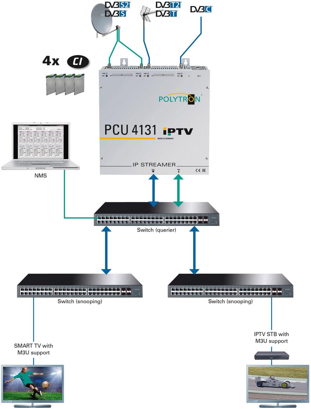
5 2. General information The transmission of television programs via digital data networks (IPTV) is becoming increasingly important. Through the use of the so-called Internet protocol, it is also possible to transmit DVB signals via a network infrastructure. In order to be able to use network lines as transmission paths for television programs, the DVB signals received in the PCU 4131 are converted into IP streams and thus made available throughout the network. Particularly in office buildings and hospitals, the supply of terminal equipment via network lines, some of which already exist, represents an elegant solution for the transmission of television programs. For new buildings and special applications, such as cruise ships, the advantage is that only an IP network has to be set up and additional coaxial cabling can be dispensed with. 3. Description The IP Streamer PCU 4131 converts DVB-S/S2, DVB-T/T2 and DVB-C signals into IP streams. The integrated CI interfaces enable the central decoding of transmitter content. The fed-in signal is made available throughout the IP network and can be directly received by PCs / notebooks with appropriate software, IPcompatible TV sets or set-top boxes (STBs) that support the "DVB-IPTV" standard. The IP Streamer can be programmed quickly and easily via the web browser user interface. The selected settings can be printed out, saved and transferred to other devices, e.g. via USB stick. The integrated LAN connection allows remote control of all parameters. 4. Scope of delivery 1 x PCU x Power cable 1 x LAN patch cable 1 x Operating instructions 1 x Installation accessories 5. Input circuit With the PCU 4131, the signals are fed directly to the input tuners. Due to the triple tuners, there are 4 inputs for SAT signals and 4 inputs for terrestrial signals (DVB-T/T2 or DVB-C). The SAT inputs Tuner #1 and Tuner #2 are supplied with an additional 12 V DC voltage for LNB supply. This can be switched by jumpers J1 and J2. A 12 V supply voltage for the terrestrial range can be applied to Tuner #4 by plugging in Jumper J3. The operating states are indicated by LEDs. 5


6 J1 > 12V on/off SAT-Tuner 1 J2 > 12V on/off SAT-Tuner 2 J3 > 12V on/off Tuner 4 Terr. 6. Assembly The IP Streamer must be installed in a well-ventilated room. The ambient temperature must not exceed 45 C. It must be ensured that the air can circulate freely through the ventilation holes, this applies especially with horizontal 19" mounting. And a minimum distance of at least 15 cm from the ventilation holes must be maintained so that the air can circulate freely. The mains plug must be pulled out for installation or when working on the wiring. 15 cm = Heat build-up!!! 15 cm 6.1. Grounding The device must be grounded in accordance with EN Strip the cable insulation of the grounding cable (4 mm 2 ) by approx. 15 mm. - Push the stripped end under the grounding screw and tighten the screw firmly. 6


7 7. Installation Connecting the input signals Connect SAT signals directly or via distributors to the corresponding tuner inputs. The SAT inputs Tuner #1 and Tuner #2 have a 12 V DC voltage for LNB supply. DVB-T and DVB-C are connected via the Terr. input. An optional 12 V supply is available at the terrestrial input Tuner #4. Please make sure that the current consumption of 250 ma per input is not exceeded. A total of 500 ma is available. Input 1 Terr. Input 2 Terr. Input 3 Terr. Input 4 Terr. Input 1 SAT LNB-DC Input 2 SAT LNB-DC Input 3 SAT Input 4 SAT Plugging in the CI modules To insert the CI modules, the covers must be removed. The picture shows the assignment of the CI slots to the inputs. Always insert the module with the label facing forward (towards the cover). 7

8 7.1. Pre-programming The inputs and outputs of the device are pre-programmed ex works with a standard frequency assignment. To receive the pre-programmed ASTRA transponders, the SAT inputs must be connected to the "Horizontal High" level as described above. SAT Input Transponder Symbol rate ARD Digital HH ksym ZDF Vision HH ksym SAT.1 / Pro Sieben HH ksym RTL World HH ksym ASTRA Das Erste ZDF SAT.1 RTL Television BR Fernsehen Süd 3sat Pro Sieben RTL2 hr-fernsehen KiKA kabel eins VOX IP output parameters ex works IP address Port Protocol UDP MPTS disabled IP address Port Protocol UDP MPTS disabled IP address Port Protocol UDP MPTS disabled IP address Port Protocol UDP MPTS disabled IP parameters of the factory pre-programmed TV channels: 8

9 7.2. Input level To ensure flawless reception, make sure that the level at the inputs is between 50 and 80 dbµv. When receiving digital signals it is advantageous to have a lower input level instead of an excessively high one. If the input level is too high, an attenuator should be used LAN connectors and Status LED Status LED Network management port Streaming output 9
.")
. Notes: PC / notebook and the IP streamer must be in the same network / IP address range.")
10 8. General programming After connection, the device runs through an internal routine and all 4 channels are set to the previously stored data. During this time, the Status LED flashes green. A connection between the PCU 4131 and the PC / notebook can only be established after the Status LED lights up permanently green or orange Initial setup The PCU 4131 is configured via the Network Management System (NMS) Establishing a connection via the browser Connect the PC or notebook directly to the network management port using a suitable CATx LAN cable. The input window depends on the selected browser (Chrome, Firefox, Internet Explorer, etc.). Notes: PC / notebook and the IP streamer must be in the same network / IP address range. Cookies must be accepted and JavaScript must be enabled. Use current browser versions. Enter the following IP address in the search bar of the web browser: Username: admin Password: password Then click OK to establish the connection. If the factory IP address of the IP streamer is lost or forgotten, it can be reset to the factory setting ( ) as follows: Pull the mains plug. Press and hold push-button TA1 on the IP board. Reconnect the mains plug. Wait until the Status LED flashes red / green alternately. Now the IP address is reset and the push-button can be released. 10

11 8.2. Programming of the device parameters After successful network access, the following overview window is displayed: All settings of the input and output parameters can be made via this input window. The status display is automatically updated every 3 seconds. In the upper part of the menu the device data, such as type, serial number, hardware version and the software versions for CPU, IP and CI controller are displayed. The information about the total data rate is also displayed there. The channel-related setting and selection options for MPTS, IP address, port and protocol are displayed in the lower part of the menu. 11
12 Input parameters for SAT reception DVB > Input signal TP > Transponder frequency Select type of input signal -> If DVB-T/T2 or DVB-C is selected, please continue reading the input parameters for the terrestrial range. Enter transponder frequency Auto > LO frequency SR > Symbol rate The required frequency is set automatically, but can be set to 09750, or another OTHER frequency. Enter symbol rate Search > Scan Tuner Locked If the tuner identifies the transponder, Tuner Locked is displayed in the upper field. After pressing the Search button, the data is taken over and the desired channel is set. 12

13 Reception conditions (DVB-S/S2) The quality of the input signal can be evaluated via the bit error rate BER and the signal-to-noise ratio SNR. These depend on the quality of the reception conditions and the SAT signals. Recommendation: Bit error rate BER should be 1e-6. For the SNR signal-to-noise ratio SNR, the illustrated guidelines apply. The corresponding values of the FEC (forward error correction) can be taken from the tables of the satellite operators. If, for example, the transponder has an FEC of 5/6, at least 9 db must be displayed in the SNR field to ensure "good" reception. FEC gut sehr gut 1/2 5-7dB 8-11dB 2/3 7-9dB 10-13dB 3/4 8-10dB 11-14dB 5/6 9-11dB 12-15dB 7/ dB 13-16dB 13
14 Input parameters for the terrestrial range TP > Frequency BW > Channel bandwidth The type of input signal is automatically displayed. Enter input frequency Selection 7 or 8 MHz PLP > Service selection (DVB-T2) Search > Scan After pressing the Search button, the data is taken over and the desired channel is set. Select PLP value If the tuner identifies the transponder, Tuner Locked is displayed in the upper field. Reception conditions (DVB-T/T2/C) The quality of the input signal can be evaluated via the bit error rate BER and the signal-to-noise ratio SNR. These depend on the quality of the reception conditions and the signals. Recommendation: Bit error rate BER should be 1e-6. The limits for the signal-to-noise ratio SNR are 26 db for DVB-T and 32 db for DVB-T2. 14
 Click on Menu * Input & MPTS Settings MPTS On or Off UDP or RTP Taking over the settings for each channel strip MPTS can be switched on or")
15 Output parameters MPTS (Multiple Program Transport Streams) Click on Menu * Input & MPTS Settings MPTS On or Off UDP or RTP Taking over the settings for each channel strip MPTS can be switched on or off separately for each channel strip -> Factory setting: Off When MPTS is switched off, the factory default SPTS streams are active (see section ). The network protocol can also be selected separately for each channel strip -> Factory setting: UDP For further information on IP address and port, see section 7.1. (Input presetting). Clicking on Set takes over the settings for each channel strip. Note: In MPTS mode, the EPG function (EIT insertion) is permanently switched on by default and can t be deactivated. It must be ensured that sufficient bandwidth is available in the IP network. 15
16 Output parameters SPTS (Single Program Transport Stream) Click on Menu * SPTS Settings Now the following dialog window (here with the factory settings) is displayed: SPTS stream On or Off EPG data On or Off UDP or RTP The IP addresses, ports and network protocols can be set separately for each service (program) either manually or automatically via the control panels below. The network protocol can be selected separately for each service (program) -> Factory setting: UDP The SPTS stream can be switched on or off separately for each service (program) by placing a hook. Note: In SPTS mode, the EPG function (EIT insertion) is switched off by default and can be activated as shown above. When it is activated, it must be ensured that sufficient bandwidth is available in the IP network. 16
 of the currently active SPTS streams is created and can be saved on the PC / notebook (download directory). This file can then be used to transfer the progr")
17 Create an M3U list In SPTS mode it is possible to create an M3U list as follows: By clicking on Download M3U-List, an M3U list (file name: dvb_ip.m3u) of the currently active SPTS streams is created and can be saved on the PC / notebook (download directory). This file can then be used to transfer the program list e.g. to PCs / notebooks with corresponding software, IPcompatible TV sets or set-top boxes (STBs) that support the "DVB-IPTV" standard. The prerequisite is that these devices support the import of M3U lists. 17
, the corresponding input fields are highlighted in red as follows: After correcting and")
18 Identification of incorrect data entries In the event of an error (e.g. double assignment of the IP address), the corresponding input fields are highlighted in red as follows: After correcting and entering all data, they must be saved again by clicking on Save. 18


19 CI menu Click on CI-Menu * CI 1, CI 2, CI 3 or CI 4 Exemplary display after clicking on CI 1 Menu lines with an arrow in front are selectable and/or contain submenus. The menu structures always depend on the CAM manufacturer. 19
 An additional Service List button is displayed next to the Search button.")

20 8.3. Service list (program list) If certain services within a transponder are not desired at the output, they can be removed. You can also use this function to select encrypted services for decryption Delete and add Services (programs) An additional Service List button is displayed next to the Search button. This is only active if the tuner is locked. A click on the Service List button opens the following window. The list of services available at the input is displayed on the left. On the right side the services contained in the output signal are listed. Clicking a service in the inbox and clicking Add adds that service to the outbox (double-clicking a service in the inbox automatically adds it to the outbox). Clicking a service in the output list and clicking the Remove command removes this service from the output list (double-clicking a service in the output list automatically removes it). With a click on the Save / Back button the output list is saved and the window is closed automatically. If you want to use only a few services from a transponder with many services, you can first click Remove All and then select the required services. 20
21 Selection of the channels to be encoded Insert the CAM module with the corresponding smartcard when switched off. If there is no recognition or if no CAM module is inserted, a corresponding message will be displayed: If the CAM module with the corresponding smart card was not detected, no services can be decrypted! However, encrypted and unencrypted services can always be distributed together. Select the required services to be decrypted from the output list by placing a hook. With a click on the Save / Back button, the output list is saved and the window is automatically closed. The CAM modules should always be plugged in when the device is switched off. 21
22 Assigning program positions via the M3U list The prerequisite is that the IP reception devices support the reading and evaluation of M3U lists. Click on Menu * SPTS Settings The IN display refers to the channel strip in which the program is contained. 22
23 The required program position can be entered in the CH No column. These programs are then sorted one after the other in the M3U list. Programs that do not have a reference number are placed after the marked programs. Saving the settings 23
")
 Network Name: Can be freely assigned by the user.")
24 Device NIT After selecting Device NIT, the following screen appears, where further entries are possible: Switch device NIT on or off as required (switched on by default) The pairing of ONID and TSID identifies the transponder. Saving the settings Note: Please pay attention to plausibility and/or overlaps during data entry! Network ID: Factory setting 3002 (modification possible) Network Name: Can be freely assigned by the user. Country: TSID New: Factory setting Germany (modification possible) The country setting should match the receiver setting. If required, a new TSID can be assigned. We recommend to use hexadecimal values within the range of F001 and FFFE. 24

 must be entered. Save the overview with the file name \"DVB_IP.rtf\". The file format.")
25 8.4. Storage of programming / Reset IP Streamer It is possible to save an existing programming on a PC / notebook or to load it from the same. In this way it is possible to archive device constellations. If required, the IP Streamer can be reset to the factory settings Storage of settings or overviews Click on Settings * Save / Load Settings Store programming on a PC / notebook. A directory and a file name (e.g. "settings.dip") must be entered. Save the overview with the file name "DVB_IP.rtf". The file format.rtf can be opened, edited and printed with Microsoft Word, Open Office or WordPad. 25
 in the directory and open it. The data will then be loaded automatically within about 45-60 seconds. 8.4.3.")
26 Upload of settings Via the menu item Load Settings the upload of an existing programming from the PC / Notebook to the IP-Streamer PCU 4131 is possible. To do this, select the corresponding.dip file (e.g. "settings.dip") in the directory and open it. The data will then be loaded automatically within about seconds Reset device to factory settings Click on Settings * Reset Headend and follow the instructions. 26

27 8.5. Network settings Click on Menu * Network Settings Now the following dialog window is displayed: Factory setting: v2 (currently no selection option) With Save all changes are stored. The following restart can take up to one minute. Note: The IP addresses listed are only examples. All addresses must be adapted to the "local network". If this information isn t known, the responsible IT specialist (m/f/d) should be contacted! 27
28 By default, the IP Streamer PCU 4131 has the following IP address: If the system is used in a network with a different network address, the IP address of the PCU 4131 must be adapted accordingly. Example: The PC operated in the network has the following settings: IP address: network share host share The IP address of the PCU 4131 may only differ from the connected PC / notebook in the last block (host share). Not allowed are the digits 0, 255 and all already used! Example IP address of the PCU 4131 in this application: or factory IP address. 28

29 8.6. Diagnostic The "Diagnostic" menu is used for service purposes and can be helpful for telephone error analysis via the Hotline +49 (0) 7081 / The status display is automatically updated every 3 seconds. CAM-Plugged: indicates if the CAM module is plugged in CAM-Init: indicates if the CAM module is detected Descrambling: indicates if all selected programs are decrypted Menu header display: Act. Operating Temperature: Max. Operating Temperature: Total Operating Hours: Critical Operating Hours: approximate current ambient temperature maximum measured ambient temperature number of hours in operation operating hours above 45 C ambient temperature The indicated temperatures only correspond to the actual value in the case of professional, vertical installation and closed housing cover. 29

30 8.7. LED key LNB green: 12 V power supply off: no voltage supply Tuner green continuous: tuner logged green flashing: tuner not logged FPGA green: configured, ready to operate off: failure 12 V green: 12 V from power supply provided off: power supply error CI green: CAM 1-4 detected off: no CAM detected Status green: all tuners logged, ready for operation orange: various functions during programming LNB power Terr. power Tuner FPGA 12 V power CI Status 30

31 8.8. Software update The Software Update menu is used to update the controller software of the device. The prerequisite is that the latest software is installed on the PC / notebook. The latest software can be found on in the Service / Software Download area. The programming of the input and output parameters carried out in section 8.2. is not affected by this. Important: Please follow the update instructions carefully. Do not turn off the unit or unplug the power cord from the wall outlet. Failure to follow the instructions or interrupt the power supply while installing the new controller software may interrupt the update process and cause the unit to stop responding or require repair. Click on Menu * Software Update 31

32 Use Select to find the appropriate folder with the update file, select the.bin file and open it. Now the matching of the software data is started, the fields with the software versions are marked in colour: Green means: Software is up to date. Orange means: More recent software exists, an update is possible. The individual software files can be updated selectively. To do this, select the desired update(s) in the Update line by hooking and then click on Upload. The software files are now uploaded one after the other. The IP streamer is then rebooted and the new software will be installed. 32


33 Teletext ON / OFF Click on Extras * Teletext Settings Switch teletext on or off as required. Then store by clicking Save. Note: Factory setting -> Teletext is switched on! 33


34 Change factory logon data (user and password) Function to protect against unauthorized access to the menu structure and device data. Note: Please make sure to note the serial number, as this is required to reset the password if necessary. The serial number is displayed on the Overview window: Should the password be lost or forgotten, we are happy to help with the general password reset. For this we definitely need the serial number of the device. The serial number can also be found on the label on the outside of the device housing. The general password reset can only be done by POLYTRON. For this process we generate a new password with which the operation can be unlocked again Password protection is activated by default and can be configured as follows: Click on Extras * Password Settings 34
35 Change Username and Password as follows Confirmation: Password matches the specifications or is identical If required, assign a new user name (consisting of letters, numbers or special characters in any order and length) in the Username field. In the New Password field, enter the new password with at least 6 digits (consisting of letters, numbers or special characters in any order). Then enter the new password again in the Confirm Password field. Click Change Password to save the new password. Note: After changing / saving the new login data and the subsequent call of another input mask, the login data is queried again. 35

36 9. Application examples Administration by webbrowser 4x MPTS or up to 128x SPTS Middleware Billing system Personal welcome Hotel TV channel 36
37 37

38 10. Technical data 38
39 Notes 39
40 Polytron-Vertrieb GmbH Postfach Bad Wildbad Zentrale / Bestellannahme H.Q. / Order department + 49 (0) / Technische Hotline Technical hotline + 49 (0) / Telefax + 49 (0) / Internet info@polytron.de Technische Änderungen vorbehalten Subject to change without prior notice Copyright Polytron-Vertrieb GmbH 40
PCU Compact Headend. User manual MADE IN GERMANY V3
 PCU 4141 Compact Headend User manual MADE IN GERMANY 0901789 V3 Contents 1. Mounting and safety instructions 3 2. General information 5 3. Description 5 4. Scope of delivery 5 5. Input circuit 5 6. Assembly
PCU 8112 / Compact Headend. User manual MADE IN GERMANY
 PCU 8112 / 8122 Compact Headend User manual MADE IN GERMANY 0901906 1 Contents 1. Mounting and safety instructions 3 2. General information 5 3. Description 5 4. Scope of delivery 5 5. Input circuit 5
TSM 1000 HD-C TSM 1000 HD-CF
 TSM 1000 HD-C TSM 1000 HD-CF User Manual MADE IN GERMANY 0901743 V1 Table of contents Page 1. Hazard and safety information 3 2. General 5 3. Description 5 4. Scope of supply 5 5. Input circuit 5 6. Assembly
PCU 8510 / Compact Headend. User manual MADE IN GERMANY V3
 PCU 8510 / 8520 Compact Headend User manual MADE IN GERMANY 0901842 V3 Contents 1. Mounting and safety instructions 3 2. General information 5 3. Description 5 4. Scope of delivery 5 5. Input circuit 5
Application examples. 2 Tel. +49 (0)7081 / Fax +49 (0)7081 / Office buildings. Cruise ships. Hotels.
7081 / Fax +49 (0)7081 / Office buildings. Cruise ships. Hotels.") IP Streamer POLYTRON IP streamer The transmission of TV channels via digital data networks (IPTV) is getting more and more important. The headend PCU 4131 converts the received DVB signals into IPTV signals
IP Streamer POLYTRON IP streamer The transmission of TV channels via digital data networks (IPTV) is getting more and more important. The headend PCU 4131 converts the received DVB signals into IPTV signals
QAM 16 EM. Operating instructions MADE IN GERMANY. 0901xxx V1
 QAM 16 EM Operating instructions MADE IN GERMANY 0901xxx V1 Table of Contents Seite 1. Hazards and safety instructions 3 2. General Information 5 3. Device models 5 4. Description 5 5. Scope of delivery
AVE HOME FAGOR CVBS TO DVB-T ENCODER MODULATOR. Fagor Electr6nica
 AVE HOME CVBS TO DVB-T ENCODER MODULATOR FAGOR Fagor Electr6nica TABLE OF CONTENTS 1. SPECIFICATIONS... 12 1.1 Product Overview... 12 1.2 Appearance and Description... 12 1.3 Diagram... 13 1.4 Characteristics...
HD-1603 Single Input MPEG-4 DVB-T HD Encoder/Modulator User Guide and Install Manual
 ZyCastR digi-mod HD Range digi-mod HD-1603 www.digi-modbyzycast.com HD-1603 Single Input MPEG-4 DVB-T HD Encoder/Modulator User Guide and Install Manual Table of Contents www.digi-modbyzycast.com Safety
MOI-V Linux dvblast tvheadend VDR Operating Instructions
 MOI-V Linux dvblast tvheadend VDR Operating Instructions Dear Customers, Thank you very much for choosing TBS products. The professional IPTV streamer MOI-V supports up to 6 built-in TV tuner PCI-e cards
Z-IP Stream 004/008. User Guide and Installation Manual. Four or Eight Input QAM Encoder / Modulator
 Z-IP Stream 004/008 User Guide and Installation Manual Four or Eight Input QAM Encoder / Modulator MPEG-2 / H.264 HD ENCODER with QAM /IP/ & ASI Outputs Contents Safety Precautions... 3 Package Contents...
Table of Contents. 1. Safety Use. 2. General Description. 3. Connection Diagram. 4. Operations and Management. 4.1 Display Status. 4.
 DTM-HD01 Thank you for buying this encoder modulator. Please read this manual carefully to install, use and maintain the encoder modulator in the best conditions of performance. Keep this manual for future
MyM-3S Micro Master. Installation Guide. English. design for TV
 MyM-3S Micro Master Installation Guide design for TV 1 CONTENT 1. Introduction 2. Unpacking the unit 3. Connections and indications 4. IP settings 5. Menus and settings 5.1 Overview menu 5.2 Input settings
User Manual. UNIVERSE Ref. 8600
 User Manual UNIVERSE Ref. 8600 No part of this manual may be copied, reproduced, transmitted, transcribed or translated into any language without permission. Unitron reserves the right to change the specifications
MyM Pro 3S/6S Installation guide
 MyM Pro 3S/6S Installation guide CONTENT 1. Introduction 2. Unpacking the unit 3. Connections and indications 4. IP settings 5. Menus and settings web ui 5.1 Overview menu 5.2 Input settings 5.3 Output
QAM MODULATOR CI. 4 x DVB-S/S2/T/T2/C+CI 4 x DVB-T/C + IP. Operation Manual
 QAM MODULATOR CI 4 x DVB-S/S2/T/T2/C+CI 4 x DVB-T/C + IP Operation Manual 1 1. IMPORTANT SAFETY PRECAUTIONS INFORMATION READ THE FOLLOWING WARNINGS BEFORE YOU USE YOUR DEVICE WARNING The following safety
HD4112 Quad HDMI MPEG2 HD DVBT Encoder Modulator U S E R M A N U A L
 HD4112 Quad HDMI MPEG2 HD DVBT Encoder Modulator U S E R M A N U A L HD4112 Manual Rev 1 Contents 1. GENERAL 1.1 Description 1.2 Specifications 2. INSTALLATION 2.1 What s in the Box 2.2 Connection 2.2.1
MyM Pro T2 Installation guide
 MyM Pro T2 Installation guide CONTENT 1. Introduction 2. Unpacking the unit 3. Connections and indications 4. IP settings 5. Menus and settings web ui 5.1 Overview menu 5.2 Input settings 5.3 Output settings
User Manual. UNIVERSE Ref SW Release
 User Manual UNIVERSE Ref. 8600 SW 1.3.0.Release No part of this manual may be copied, reproduced, transmitted, transcribed or translated into any language without permission. Unitron reserves the right
Digital Tuner Streamer
 Digital Tuner Streamer This Manual Apply to the MTRX 4/8 Tuner To IPTV Systems On 8 Tuners Systems, The inputs are all assigned to the 8 Tuners Only and no asi Web-NMS Version: 1.03 Software: 1.00 Hardware:
SAT IF distribution system
 7. Technical specifications Type cs43 RF input frequency range pr. 50-350 MHz inputs number 4 level pr. 55...88 dbµv 60...93 dbµv symbol rate 3 45 Ms/s return loss/impedance > 0 db/75 Ω LNB powering/control
Figure 1: V 713 CI plug-in card
 Version 04-2013A Device description Device description The delivery consists of the following parts: V 713 CI and X-DVB-CT2/PAL duo CI plug-in cards 2 connection cables with F connectors, 450 mm & F socket-f
CompactMax-2 DVB-S/S2 TO DVB-T2 TRANSMODULATOR - 0 MI2100 -
 CompactMax-2 DVB-S/S2 TO DVB-T2 TRANSMODULATOR - 0 MI2100 - SAFETY NOTES Read the user s manual before using the equipment, mainly "SAFETY RULES" paragraph. The symbol on the equipment means "SEE USER
HDTV Digital ASI PHDA 8007 ASI. English. Phone: +49 (0) 911 / Fax: +49 (0) 911 / Internet:
 911 / Fax: +49 (0) 911 / Internet:") HDTV Digital ASI PHDA 8007 ASI KLASSE CLASS English GSS Grundig SAT Systems GmbH Beuthener Strasse 43 D-90471 Nuremberg Phone: +49 (0) 911 / 703 8877 Fax: +49 (0) 911 / 703 9210 E-mail: info@gss.de Internet:
HDTV Digital ASI PHDA 8007 ASI KLASSE CLASS English GSS Grundig SAT Systems GmbH Beuthener Strasse 43 D-90471 Nuremberg Phone: +49 (0) 911 / 703 8877 Fax: +49 (0) 911 / 703 9210 E-mail: info@gss.de Internet:
Operation and Installation Guide
 Operation and Installation Guide HDS2800 Series Encoder Modulator High Definition (HD) Digital COFDM MPEG2 and H.264 Modulator with IP Multicast. 19 Rack Mount Revision 4.0 Firmware version Released File
HD-1600 Single Input MPEG-4 DVB-T HD Encoder/Modulator User Guide and Install Manual
 digi-mod HD Range digi-mod HD-1600 www.resi-linx.com HD-1600 Single Input MPEG-4 DVB-T HD Encoder/Modulator User Guide and Install Manual Table of Contents Safety Precautions 2 Package Contents 2 Product
User Manual. UNIVERSE Ref. 8600
 User Manual UNIVERSE Ref. 8600 No part of this manual may be copied, reproduced, transmitted, transcribed or translated into any language without permission. Unitron reserves the right to change the specifications
user manual Colosseum 8500D
 user manual Colosseum 8500D No part of this manual may be copied, reproduced, transmitted, transcribed or translated into any language without permission. Unitron reserves the right to change the specifications
DXI-800 DVB-S/S2/T to IP streamer User Manual
 DXI-800 DVB-S/S2/T to IP streamer User Manual 1. Purpose of use DXI-800 is HD compatible IP streamer designed for a processing satellite and terrestrial signals to data broadcast (IP) connected to Ethernet.
User guide. IP output module - Art. No A
 User guide IP output module - Art. No. 492072 891080A GB Contents Contents Disposal... 3 Box content... 3 IP output module... 3 Labels... 4 Installation of IP modules... 5 Installation of extender boards...
Operation and Installation Guide
 Operation and Installation Guide HDS2800 Series Encoder Modulator High Definition (HD) Digital COFDM MPEG2 and H.264 Modulator with IP Multicast. 19 Rack Mount Wall Mount Revision 0.1 Firmware version
HD168Bi Quad CVBS/HDMI HD DVBT Encoder Modulator U S E R M A N U A L
 HD168Bi Quad CVBS/HDMI HD DVBT Encoder Modulator U S E R M A N U A L Contents 1. GENERAL 1.1 Description 1.2 Specifications 2. INSTALLATION 2.1 What s in the Box 2.2 Connection 2.2.1 DEVICE Programming
Single cable multiswich programmer PC102W
 Single cable multiswich programmer PC102W 1. Product description The PC102W - single cable multiswich programmer (in the text - programmer) is useful instrument while configuring and troubleshooting SAT
BY-HPE11KTA. Operating Instructions. Coaxial - LAN Converter with PoE function. Indoor Use Only. Model No. Attached Installation Guide
 Operating Instructions Coaxial - LAN Converter with PoE function Model No. Indoor Use Only BY-HPE11KTA Attached Installation Guide Before attempting to connect or operate this product, please read these
IxStream Headend. Quick Guide - Begin working with the IxStream headend. IX-Streamer, rev 1.1
 IxStream Headend Quick Guide - Begin working with the IxStream headend IX-Streamer, rev 1.1 Introduction... 3 Example setup... 3 Access the headend... 4 Important Concepts... 5 Push Config... 5 EMM...
User manual Transmodulators. Ref. 5103S/5103T/5103Q/5130
 User manual Transmodulators Ref. 5103S/5103T/5103Q/5130 Contents 1 Introduction 2 1.1 The ProQuad range................................ 2 1.2 Modular system solution.............................. 4 1.3
Figure 1: V 613 CI plug-in card
 Version 02-2013A Device description Device description The delivery is comprised of the following parts: V 613 CI and X-DVB-S2/PAL duo CI plug-in card 2 connection cables with F connectors, 450 mm & F
VIDEO GRABBER. DisplayPort. User Manual
 VIDEO GRABBER DisplayPort User Manual Version Date Description Author 1.0 2016.03.02 New document MM 1.1 2016.11.02 Revised to match 1.5 device firmware version MM 1.2 2019.11.28 Drawings changes MM 2
White Paper Customized IPTV Setups with TVCaster Server Appliances
 White Paper Customized IPTV Setups with TVCaster Server Appliances Copyright 2018 by GMIT GmbH, Berlin, Germany TVCaster by GMIT represents the next generation of IPTV server appliances. TVCaster is a
SZU OPERATING INSTRUCTIONS SAT NAVI
 SZU 21-00 O P ER ATI N G I N S T R U C T I O N S SAT NAVI Operation Instructions SZU 21-00 Safety Notes Turn off the receiver or any used power supply before installing, to avoid short-circuit. Installation
Quick installation and configuration guide STC
 Quick installation and configuration guide STC 200 REF. 4466 Contents 4 Introduction 4 General description 5 General use of the headend 6 Initial installation and configuration 6 Assembly, connection
User guide MAW-300. Ref HD Encoder & Modulator HDMI to DVB-T
 User guide MAW-300 Ref. 3030 HD Encoder & Modulator HDMI to DVB-T 1 Index Safety Instructions... 3 General Description... 4 Working Principie... 4 Technical Specifications... 5 Installations... 6 Typical
Television on IP Networks. SNS-101 (Ref. 5101) FTA or Multicrypt DVB-S IP Streamer Common Interface. Configuration and Settings.
 FTA or Multicrypt DVB-S IP Streamer Common Interface. Configuration and Settings.") Television on IP Networks SNS-101 (Ref. 5101) FTA or Multicrypt DVB-S IP Streamer Common Interface Configuration and Settings User Manual EN Configuration and Setting of the SNS-101 Streamer Module User
Television on IP Networks SNS-101 (Ref. 5101) FTA or Multicrypt DVB-S IP Streamer Common Interface Configuration and Settings User Manual EN Configuration and Setting of the SNS-101 Streamer Module User
TV4U QUAD DVB-S2 to DVB-C TRANSMODULATOR
 INSTRUCTION MANUAL Features of the new DVB-C transmodulators line Through the use of the FPGA technology the transmodulators provides the highest performance at the lowest price. Four carriers are formed
SKQ 40-0x SKQ 80-0x SKQ 40-0xM SKQ 80-0xM
 SKQ 40-0x SKQ 80-0x SKQ 40-0xM SKQ 80-0xM 8PSK/QPSK/Multituner DVB-C Quattro/Octo modules Operation instructions Operation instructions SKQ 40-0x SKQ 80-0x SKQ 40-0xM SKQ 80-0xM Table of contents 1. Product
ATSC TO IP Gateway 8X
 ATSC TO IP Gateway 8X USER MANUAL Vingtor-Stentofon IPTV System TECHNICAL MANUAL Doc.no.A100K11719 Page 1 USER MANUAL DOC.NO.A100K11719 Document Contents 1. BASIC INFORMATION... 4 2. PRODUCT INTRODUCTION...
Professional Headend Solutions. Device manual. SAT-TV Transmodulator. DVB-S/ -S2 (8x QPSK/ 8PSK) 4x CI DVB-C (8x QAM) A-QAMOS-4CI Part N o : 5102.
 4x CI DVB-C (8x QAM) A-QAMOS-4CI Part N o : 5102.") Professional Headend Solutions Device manual A-QAMOS-4CI Contents 1. Safety and operating instructions... 3 2. Device variants... 3 3. Software options... 3 4. General... 3 5. Functional description...
Professional Headend Solutions Device manual A-QAMOS-4CI Contents 1. Safety and operating instructions... 3 2. Device variants... 3 3. Software options... 3 4. General... 3 5. Functional description...
SD4650 DVB-T HD MODULATOR. User Manual
 SD4650 DVB-T HD MODULATOR User Manual 0 TABLE OF CONTENT 1 GENERAL...2 1.1 Description...2 1.2 Specifications...3 2 INSTALLATION...4 2.1 What s in the Box...4 One power cable...4 2.2 Connection...4 2.2.1
16 channels transmodulator S2C16
 16 channels transmodulator S2C16 Vers. 1.01 USER S MANUAL S2C16 - SAT to QAM transmodulator 1. Product description S2C16 is a 16 channel transmodulator with DVB-S/S2 input and DVB-C output. It has 4 main
CompactMax-4 DVB-S/S2 TO ISDB-T TRANSMODULATOR - 0 MI2101 -
 CompactMax-4 DVB-S/S2 TO ISDB-T TRANSMODULATOR - 0 MI2101 - SAFETY NOTES Read the user s manual before using the equipment, mainly "SAFETY RULES" paragraph. The symbol on the equipment means "SEE USER
The first TV Smart Headend designed for Hospitality SOLUTIONS FOR IN-ROOM ENTERTAINMENT PROVIDERS AND INTEGRATORS
 The first TV Smart Headend designed for Hospitality SOLUTIONS FOR IN-ROOM ENTERTAINMENT PROVIDERS AND INTEGRATORS 1 FLOW IN...3 FLOW SEC...4 FLOW ENC...5 FLOW OUT...6 FLOW HUB...7 FLOW BASE...8 FLOW PSU...9
Channel processing equipment
 Technical specifications Type sdi480 RF input 4x QPSK / 8PSK COFDM / QAM frequency range 950-2150 MHz 47-862 MHz level/impedance 45-85 dbµv / 75 Ω 45-80 dbµv / 75 Ω symbol rate 2 45 Ms/s - LNB powering/control
Professional HD Integrated Receiver Decoder
 Professional HD Integrated Receiver Decoder User Manual V1.00-C Preface About This Manual This manual provides introductions to users about how to operate the device correctly. The content includes introduction
MK 8-00 MK MK 8-06 MK 16-06
 MK 8-00 MK 16-00 MK 8-06 MK 16-06 Multituner DVB-C/DVB-T compact headend Operation instructions Operation instructions MK 8-00 MK 16-00 MK 8-06 MK 16-06 Table of contents 1. Product description... 4 1.1.
Operating instructions
 Operating instructions V 505 and X-QAM 621 DVB-S2 / QAM Twin Transmodulator Pictograms and safety instructions Pictograms are visual symbols with specific meanings. You will encounter the following pictograms
T3316 IP QAM Modulator User Manual
 T3316 IP QAM Modulator User Manual SW Version: 1.02 HW version: 0.70.0.0 Web NMS version: 1.02 Intended Audience About This Manual This user manual has been written to help people who have to use, to integrate
PCM-1210 DVB COMBO METER User`s Manual
 PCM-1210 DVB COMBO METER User`s Manual 1. Main Features... 1 2. Buttons and Indicators... 2 3. How to measure... 3 4. Home menu... 4 5. Satellite... 4 5.1 Satellite Measure... 4 5.2 LNB Setting... 5 5.3
B. The specified product shall be manufactured by a firm whose quality system is in compliance with the I.S./ISO 9001/EN 29001, QUALITY SYSTEM.
 VideoJet 8000 8-Channel, MPEG-2 Encoder ARCHITECTURAL AND ENGINEERING SPECIFICATION Section 282313 Closed Circuit Video Surveillance Systems PART 2 PRODUCTS 2.01 MANUFACTURER A. Bosch Security Systems
CHENGDU DEXIN DIGITAL TECHNOLOGY CO., LTD
 NDS3208 8 in 1 MPEG-2 Encoder User s Manual NMS Version: 1.12.5 SW: 2.07 HW: 1.3 CHENGDU DEXIN DIGITAL TECHNOLOGY CO., LTD DIRECTORY Chapter 1 Product Introduction... 1 1.1 Outline... 1 1.2 Main Features...
CI-218 / CI-303 / CI430
 CI-218 / CI-303 / CI430 Network Camera User Manual English AREC Inc. All Rights Reserved 2017. l www.arec.com All information contained in this document is Proprietary Table of Contents 1. Overview 1.1
TP160 IRD. Professional HD Integrated Receiver Decoder User Manual V1.0RC
 TP160 IRD Professional HD Integrated Receiver Decoder User Manual V1.0RC Preface Symbols Definition For the symbols that might appear in this document, the meanings they represent are as the following:
Owner s Manual. Sat-Meter MSK 15. Order No.:
 Owner s Manual Sat-Meter MSK 15 Order No.: 217 100 13 Thank you for choosing our latest and most innovative satellite meter. It has been designed and manufactured to a very high standard and offers a UNIQUE
AMD-53-C TWIN MODULATOR / MULTIPLEXER AMD-53-C DVB-C MODULATOR / MULTIPLEXER INSTRUCTION MANUAL
 AMD-53-C DVB-C MODULATOR / MULTIPLEXER INSTRUCTION MANUAL HEADEND SYSTEM H.264 TRANSCODING_DVB-S2/CABLE/_TROPHY HEADEND is the most convient and versatile for digital multichannel satellite&cable solution.
Professional HD Integrated Receiver Decoder
 Professional HD Integrated Receiver Decoder GEOSATpro DSR-180ASI with 708CC User Manual V1.00-C For Support, call 888-483-4673 Preface About This Manual This manual provides introductions to users about
Assembly Instruction MUX 1916 IPM CI. Default access data: User: admin Password: geheim
 Assembly Instruction MUX 1916 IPM CI Default access data: 192.168.0.120 User: admin Password: geheim Contents 1 Safety regulations and notes...4 2 General information...6 2.1 Packing contents...6 2.2 Meaning
Operating instructions V 514 / X-QAM quad
 Operating instructions V 514 / X-QAM quad DVB-S2 / QAM Quad Transmodulator with Service-Filter Pictograms and safety instructions Pictograms are visual symbols with specific meanings. You will encounter
STM 17 HD. DVB-S2+T2/C Compact Meter. User Manual. Ref R13. CAHORS Digital CS Cahors Cedex 9 FRANCE.
 STM 17 HD DVB-S2+T2/C Compact Meter User Manual Ref 0145131R13 DVB COMBO METER 1. Main Features... 2 2. Buttons and Indicators... 3 3. How to measure... 4 4. Home menu... 5 5. Satellite... 5 5.1 Satellite
PROMAX NEWSLETTER Nº 22
 PROMAX NEWSLETTER Nº 22 TV EXPLORER HD series: H.264 / MPEG-4 AVC picture CV-100: Optical LNB adapter for TV EXPLORER MO-370: ISDB-T/T B modulator DIGITAL To TV: for Broadcast and TV Distribution PROMAX-27:
User Manual. SCR Multiswitch Ref. 9744SKY, 9746SKY, 9748SKY
 User Manual SCR Multiswitch Ref. 9744SKY, 9746SKY, 9748SKY No part of this manual may be copied, reproduced, transmitted, transcribed or translated into any language without permission. Unitron reserves
TV4U DVB-S2 to DVB-S2 TRANSMODULATOR
 TV4U to TRANSMODULATOR TV4U to TRANSMODULATOR INSTRUTION MANUAL TV4U to TRANSMODULATOR The main application of to transmodulator Experience of MVDS terrestrial broadcasting shows that carrier must be restored
Fully ly Automaticti. Motorised Satellite t TV System. User s manual. ver 3.0.
 ver 3.0 Fully ly Automaticti Motorised Satellite t TV System User s manual Customer Help Line: 1300 139 255 Support Email: support@satkingpromax.com.au Website: www.satkingpromax.com.au www.satkingpromax.com.au
-TECH DIGITAL. Explore The High DefinitionWorld. Website: Hot Line: [US] USER MANUAL
![-TECH DIGITAL. Explore The High DefinitionWorld. Website: Hot Line: [US] USER MANUAL](/thumbs/80/80689593.jpg "-TECH DIGITAL. Explore The High DefinitionWorld. Website: Hot Line: [US] USER MANUAL") -TECH DIGITAL Explore The High DefinitionWorld Website: www.jtechdigital.com Hot Line: 1-888-610-2818[US] USER MANUAL J-Tech Digital ProAV H.264 Encoder/Decoder Many to Many HDMI Extender RoHS 1 Operating
-TECH DIGITAL Explore The High DefinitionWorld Website: www.jtechdigital.com Hot Line: 1-888-610-2818[US] USER MANUAL J-Tech Digital ProAV H.264 Encoder/Decoder Many to Many HDMI Extender RoHS 1 Operating
USER MANUEL. SNIPE 2 Ref R13
 USER MANUEL SNIPE 2 Ref. 0141317R13 Contents 1. General Information 1-1. Introduction 1-2. Proper use and operation 1-3. Safety notes......... 2 3 3 2. Contents 2-1. Accessory included 2-2. Name of parts......
CM 3S-TC. Triple Transmodulator 8PSK-COFDM/QAM. User manual
 CM 3S-TC 082016 Triple Transmodulator 8PSK-COFDM/QAM User manual 1 1. Accessories... 1 2. General Description... 2 3. Installing and connections... 4 3.1. Installing and general connections... 4 3.2. Installation
MyM Pro Installation Guide
 MyM Pro Installation Guide www.wisi.se TABLE OF CONTENTS 1. INTRODUCTION 3 2. UNPACKING THE UNIT 4 3. CONNECTIONS AND INDICATIONS 5 4. IP SETTINGS 6 4.1 TCP/IP settings for Windows XP...............................
Installation and User Guide 458/CTR8 8-Channel Ballast Controller Module
 Installation and User Guide 458/CTR8 8-Channel Ballast Controller Module Helvar Data is subject to change without notice. www.helvar.com i Contents Section Page Introduction 1 Installation 2 1. Attach
Unicable II Programmer. IDLU-PROG01-OOOOO-OPP Item: Installation & User Guide
 Unicable II Programmer IDLU-PROG01-OOOOO-OPP Item: 5273 Installation & User Guide 1 2 Thank you for purchasing Inverto s advanced Unicable II programmer. Before installing and using the programmer, please
STC 160 Head-End Station Quad modulators
 STC 160 Head-End Station Quad modulators HMS 480 HMM 480 / HMM 480 OIRT Notes on the Assembly Instructions. As well as this supplementary Assembly Instructions, the Assembly Instructions for the STC 160
EdgeConnect Module Quick Start Guide ITERIS INNOVATION FOR BETTER MOBILITY
 EdgeConnect Module Quick Start Guide ITERIS INNOVATION FOR BETTER MOBILITY 493456301 Rev B April 2009 Table of Contents Installation... 1 Setup... 2 Operation... 4 Live Video... 4 Video Settings... 5 Network
Be sure to run the vehicle engine while using this unit to avoid battery exhaustion.
 CAUTION: TO REDUCE THE RISK OF ELECTRIC SHOCK DO NOT REMOVE COVER (OR BACK) NO USER-SERVICEABLE PARTS INSIDE REFER SERVICING TO QUALIFIED SERVICE PERSONNE; Please Read all of these instructions regarding
IRIG-B PTP Clock Converter Output Module Hardware Installation Manual
 IRIG-B PTP Clock Converter Output Module Hardware Installation Manual Kyland Technology Co., LTD. Publication Date: May 2012 Version: V1.2 Customer Service Hotline: (+8610) 88796676 FAX: (+8610) 88796678
English CONTENTS 1. GUIDE OUTLINE THE MENU OSD INSTRUCTION TECHNICAL SPECIFICATION TROUBLE SHOOTING...
 English CONTENTS 1. GUIDE...2 1.1 IMPORTANT SAFETY INSTRUCTIONS...2 1.2 UNPACKING...2 1.3 PRODUCT OVERVIEW& ILLUSTRATION...3 1.4 INSTALLATION OF METER...4 2. OUTLINE...5 3. THE MENU OSD INSTRUCTION...6
DVB-T USB SET-TOP BOX
 DVB-T USB SET-TOP BOX User Manual Version: 1.0 (February 2005) TRANSYSTEM INC. No.1-2 Li-Hsin Rd.I Science-Based Industrial Park, Hsinchu, Taiwan Tel:+886-3-5780393 Fax:+886-3-5784111 e-mail: sales@transystem.com.tw
Assembly Instruction STS 1916 IPM CI. Default access data: User: admin Password: geheim
 Assembly Instruction STS 1916 IPM CI Default access data: 192.168.0.120 User: admin Password: geheim Contents 1 Safety regulations and notes...4 2 General information...6 2.1 Packing contents...6 2.2 Meaning
Assembly Instructions
 Assembly Instructions English GSS Grundig SAT Systems GmbH Beuthener Straße 43 D-90471 Nuremberg Grundig SAT Systms HDTV Digital QAM PHDQ 2002 BC PHDQ 3002 BC PHDQ 4002 BC PHDQ 5002 BC KLASSE ACLASS Phone:
CM 4HD-TC. Digital encoder-modulator 4 HDMI-COFDM/QAM. User s Manual
 CM 4HD-TC 082004 Digital encoder-modulator 4 HDMI-COFDM/QAM User s Manual 2 1 CM 4HD-TC USER MANUAL 1.1 General Description 2 1 3 4 5 3 Number Description 1 HDMI Inputs. Connection to the audio/video power
Digital Satellite Module. Guide
 Digital Satellite Module Guide 2 This product fulfils the conditions stated in the EEU directives 89/336 and 73/23. Contents 3 Daily use, 4 Find out how to use the Beo4 remote control with the Digital
Re:source. Communication Module. SAT Version. Dominating Entertainment. Revox of Switzerland. E2.00
 Re:source Communication Module SAT Version Dominating Entertainment. Revox of Switzerland. E2.00 Please note: Software update! Unlike the software for the Standard communication module, the SAT control
CGA0101 Wireless Cable Gateway Quick Installation Guide
 Package Contents CGA0101 cable modem * 1 Quick Installation Guide * 1 RJ-45 CAT 5e cable * 1 Rear Panel and Hardware Connection 12 V/1.5 A Power Adaptor * 1 Telephone cord * 1 This chapter describes the
M5-H002. Multiview T-35. DVB-T to PAL / 5 channels on all TV s
 120531 M5-H002 Multiview T-35 DVB-T to PAL / 5 channels on all TV s Contents Multiview... 3 Features... 3 Caution... 3 Front & Rear Panel... 4 Connecting... 5 Programming... 6 Information... 7 Installation...8
SPECIAL SPECIFICATION :1 Video (De) Mux with Data Channel
 Mux with Data Channel") 1993 Specifications CSJ 0924-06-223 SPECIAL SPECIFICATION 1160 8:1 Video (De) Mux with Data Channel 1. Description. This Item shall govern for furnishing and installing an 8 channel digital multiplexed
1993 Specifications CSJ 0924-06-223 SPECIAL SPECIFICATION 1160 8:1 Video (De) Mux with Data Channel 1. Description. This Item shall govern for furnishing and installing an 8 channel digital multiplexed
Simple Media Platform Quick Installation Guide V1.0-N. Simple Media Platform. Quick Installation Guide
 Simple Media Platform Quick Installation Guide 1. Installation Instruction 1.1 Mounting unit to a 19 rack When selecting the installation site, try to comply with the following: Protective Ground - The
User Manual. HDMI Modulator Ref & SW Release
 User Manual HDMI Modulator Ref. 8201 & 8202 SW 1.1.1.Release No part of this manual may be copied, reproduced, transmitted, transcribed or translated into any language without permission. Unitron reserves
User manual. QAM output module. QAM output module Version F Date 08/2016 EN
 QAM output module Model Item no. QAM output module 492055 492056 Version F Date 08/2016 EN Attention! / Achtung! / Consignes de sécurité! EN Failure to comply with the specified precautionary measures
HD Digital MPEG2 Encoder / QAM Modulator
 HD Digital MPEG2 Encoder / QAM Modulator HDMI In QAM Out series Get Going Guide ZvPro 800 Series is a one or two-channel unencrypted HDMI-to-QAM MPEG 2 Encoder / QAM Modulator, all in a compact package
For installation queries contact Customer Services (0) TCR IP 4 Operating instructions
 TCR IP 4 Operating instructions") For installation queries contact Customer Services +49 - (0)3 69 25-9 00 90 kundenservice@rutenbeck.de TCR IP 4 Operating instructions GB Device overview External buttons (for manual switching) Temperature
For installation queries contact Customer Services +49 - (0)3 69 25-9 00 90 kundenservice@rutenbeck.de TCR IP 4 Operating instructions GB Device overview External buttons (for manual switching) Temperature
DS-7200HVI/HFI-SH Series DVR Quick Operation Guide
 DS-7200HVI/HFI-SH Series DVR Quick Operation Guide UD.6L0202B0019A01 Thank you for purchasing our product. If there is any question or request, please do not hesitate to contact dealer. This manual is
QAM HD Integrated Receiver Decoder with SDI/HDMI/ASI/IP Signal Outputs. User Manual B-IRD-HD-PRO-Q HD IRD
 QAM HD Integrated Receiver Decoder with SDI/HDMI/ASI/IP Signal Outputs User Manual B-IRD-HD-PRO-Q HD IRD DIRECTORY Chapter 1 Product Outline... 1 1.1 Outline... 1 1.2 Features... 1 1.3 Specifications...
User Manual PROHDMI STREAMER/MODULATOR. Ref /
 User Manual PROHDMI STREAMER/MODULATOR Ref. 5520 / 5530-5531 Contents 1. Introduction... 2 1.1. Product description... 2 1.2. Typical installation... 2 1.3. Package contents... 3 1.4. Product dimensions...
DMOD1200MS. HDMI Modulator. User Manual PLEASE READ THE MANUAL COMPLETELY BEFORE USE V.17.09
 DMOD1200MS HDMI Modulator User Manual PLEASE READ THE MANUAL COMPLETELY BEFORE USE V.17.09 CONTENTS 1. INTRODUCTION 1.1. Product Description 1.2. Package Contents 1.3. Hardware Installation 1.4. Safety
Horizon HD-STM. Combo Signal Analyzer TEST REPORT
 TEST REPORT Combo Signal Analyzer Horizon HD-STM can be used intuitively, manual is not needed perfect workmanship optimized for the day-to-day work of an installer gives all the "Must-Have" informations