Understanding IRS3B, board-stack and
|
|
|
- Harriet Miller
- 5 years ago
- Views:
Transcription

 Single edge timing: ~22ps RMS Net")
 [ns] Gary S.")
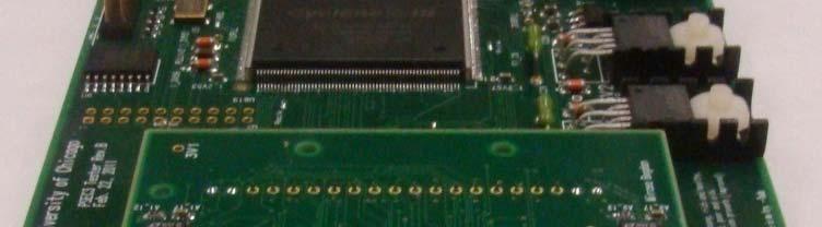
1 Understanding IRS3B, board-stack and mtc operation/calibration Calibration in progress ~31ps RMS timing difference (2 edges) Single edge timing: ~22ps RMS Net timing difference (Ch.7 Ch. 4) [ns] Gary S. Varner 2 JUL 2014 mtc Training Session #3
2 mtc Readout Roadmap Currently at about Phase 1.5 You can get us to Phase 2.5 Specifically Operators need to understand Hardware/Firmware/Software Develop real-time Data Quality Monitoring i What I hope to convey: 1. Details of the hardware: ASIC + boardstack 2. Firmware and Configuration/Operating parameters 3. Understand how to read and comprehend documentation and ask meaningful questions ( it doesn t work notably not amongst them) 2
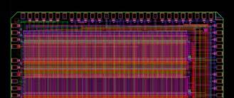
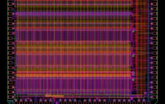
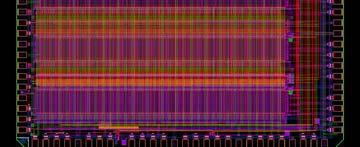
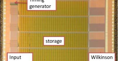
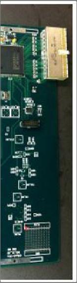
3 IRS3B Structure 3
4 Hopefully, these will start to make sense in terms of how these settings map onto operational parameters of the IRS3B ASIC 4
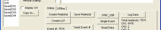
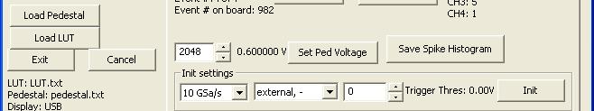
5 Simple software Once have writing template that talks to the picoblaze, tuning operational parameters of the IRS3B ASIC really easy 5

6 Servo-controls (3 parameters) Sampling speed Trigger 1-shot Width Adjust T_1_TRG Power (T_1_TRG) 100 ADC 10 Clock [ns] Output Width Trigger output Width September 22, Discharge Current [ua] 6
7 Specifically, for mtc Software Servolock? Trigger 1-shot Width Adjust T_1_TRG Power (T_1_TRG) 100 Keep Firmware Servo [ns] Output Width 10 Don t bother September 22, Discharge Current [ua] 7
8 Firmware Servo-lock 8
9 mtc software pointer 9
10 A word of caution 10
11 What limits timing? Increased Amplification: Want >100 ADC counts (>~ 60mV) for smallest pulses: Carrier Rev C ps 60-70ps 11


12 Oscilloscope on a chip? Calibration ~=?? 12


13 Oscilloscope on a chip? Calibration Modified approximation: ~ = 13
14 Calibration and Sources of Timing i Error voltage noise u timing i uncertainty t t signal height U u U t t t r rise time t r t r 1 3 f 3dB t u U t r u U n t r u U t t r r u t u r f U U s f s 3 f s f 3 db 1 *Diagram, formulas from Stefan Ritt 14
15 Calibration and Sources of Timing Error Contributions to timing resolution: Voltage uncertainties Timing uncertainties voltage noise u timing uncertainty t signal height U *Diagram from Stefan Ritt rise time t r Of these contributions: Random irreducible (without hardware redesign) Deterministic in principle can be calibrated away. Let s talk about where the deterministic pieces come from and what has been done about them. 15
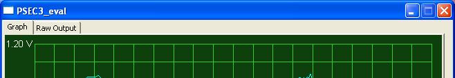
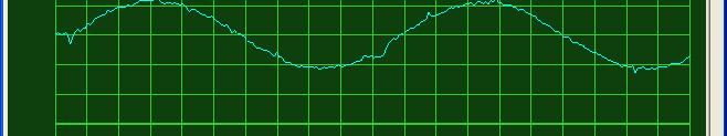
16 First ASIC Calibration Pedestals Each storage cell has its own offset value. Measure with no signal linput. These offsets must be removed in order to see a clean(er) signal. We call this pedestal subtraction. 32k pedestals per channel (quarter million per ASIC!) Example: Before pedestal subtraction After pedestal subtraction 16
17 Comparator Transfer Functions Wilkinson comparator. Ramp is supplied to all storage cells. Comparator output fires when ramp exceeds stored voltage. Signals are stored with DC offset to fit into the comparator s dynamic range. Offset varies somewhat for each storage cell. This is what we try to remove with pedestal correction. Comparator response is nonlinear. Example shown for IRS3B comparator pedestal 17
18 AC vs. DC Response, Pulse Persistence Previous slide transfer functions measured with DC inputs. AC response may not be the same! Why not? One example persistence. Voltage has some dependence on previously stored voltage. Example from Eric Oberla, PSEC3 ASIC. This shows a pulse whose ghost persists for one or more cycles after the pulse. The inverse is almost certainly true: a pulse does not reach its full height due to Original pulse Ghost pulse result of writing pedestal voltage onto original pulse 1 cycle later. 18
19 Timing Uncertainties and Timing Calibration Time interval between delay line stages has intrinsic variation. Not accounting for this properly causes significant timing errors Differential (DNL) and Integral (INL) [run-out] Non-Linearity 19
20 One calibration scheme Have tried many, and they each have their merits and drawbacks 20
21 A word of caution (anon) 21
22 Timing Resolution as a Function of Sample Number 75ps 50ps Should be taking a lot of such data and analyzing it to understand timing error contributions Timing resolution as a function of sample number of the threshold h crossing (pulser data). 22 Indicative of noise contributions.
23 IRS3D Improvements over IRS3B 1. Improved Trigger Sensitivity 2. Timebase Servo-locking 3. dt hardware adjust 4. Improved linearity/dynamic range 5. Improved Wilkinson ADC 6. No high current at power-onon = originally reported for TARGET7/X = demonstrated initially (TARGET7/X), detailed timing confirmed = LABRADOR4 independent confirmation = All ASICs since IRS3C 23
24 Trigger Threshold Improvement A significant improvement for smaller pulses where first strike initiation of the MCP charge development is retarded 16x doesn t improve further, as already at the signal-to-noise limit 24
25 Timebase servo-locking (DLL) dttrim= DLL Coarse Tuning Vadj jn (V) Sampling Rate [GSPS] IRSX SST_FB (tap stage) Feedback Tap Number [of 128] Sampling tracks target delay Target sampling rate: 2.8 GSa/s Feedback tap = 121 (indirect RCO feedback mechanism injects asynchronous noise into timebase generator, degrading di timing i performance so this is a significant ifi improvement) 25
26 Time base non-uniformity 2.6 GSa/s 10-15% of dt typical If can correct, reduces processing time dramatically, as this is the most computationallyintensive aspect of fast feature extraction 26
27 Roughly Adjusted dt Sampling 27GSa/s 2.7GSa/s Sampling not working 3.2GSa/s Simple, linear dt slew correction Still room for improved tuning Sample # Sample # 27
28 Observed IRSX noise ~1.4mV Non-gaussian distributions expected for small noise amplitude due to non-linearity in Gray-code least count Take away message: noise is comparable, or better than IRS3B, and acquired while sampling continues to run 28
29 IRS3B IRS3D 29
30 Improved Residuals, repeatability Note: IRS3D -- no comparator bias tuning yet done ~1% Integral deviation from 3 rd -order over key sensitivity range Shape repeatable samplesample (common lookup table, with only pedestal offset) 30
31 Useful Diagnostic tool Quite sensitive to yuckiness in the data 31


32 Improved Wilkinson cross-feed IRS3B Broadening at the extrema Breakdown of simple ellipses expect otherwise Kinks/inflections i hard to manufacture without some type of digital interference kinks IRS3B broadening Broadening is AC noise In vernacular of CTA colleagues pinch-off kinks Much improved some additional improvement expected with linearity correction 32

33 Result: visually nicer waveforms IRS3B Difference most evident at the extrema of the waveforms jumps IRS3B compression 33
34 IRS3D timing (no detailed timebase calibration) 60 ~31ps RMS timing difference 50 (2 edges) 40 Single edge timing: ~22ps RMS Net timing difference (Ch.7 Ch. 4) [ns] Sing gle photon timing [ps] Single Photon Timing Electronics Contribution [ps] 40ps TTS 35ps TTS For stretch goal of <= 50ps single p.e. timing, the electronics contribution should be <= 36ps for 35ps MCP-PMT TTS (best case) [<= 30ps for 40ps MCP-PMT TTS (worst case)] IRS3D looks capable of achieving this goal. 34
35 Summary Day 3 Final batch of detailed information presented Hopefully useful All of these concepts are straightforward, though much, much, much to be assimilated il all at once Typically 3+ times through needed to get it Essential issues to be addressed d for quality mtc data-taking: Are register configurations/feedbacks being set properly? Can we tell ll? (meaningful DQM tools?) Understanding what is being done? Calibration! (and diagnostics) 35
36 Back-up slides 36
37 Resources (where to find more) Hardware: IRS3B webpage: Board stack schematics: phys hawaii edu/~mza/pcb/itop/carriers/index.html (Interconnect) Firmware: References link: hawaii homepage html Repositories: Software: Will talk about next time:
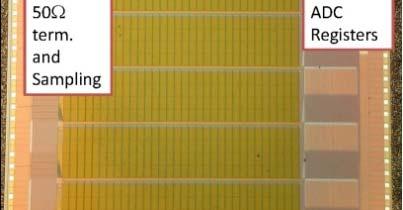
38 Simplified IRS3B Block Diagram Input Analog Input Sampling SA1 (64) SA2 (64) Transfer A1 (64) B1 (64) A2 (64) B2 (64) Storage W0 W4 W508 W1 W2 W3 W511 Readout x8 12 bit counters (x64) Ramp Generator Timing Generator Per channel: Single input line Common to all channels: 128 sampling cells/capacitors Timing generator 256 transfer cells/capacitors Ramp generator 32,768 storage cells/capacitors 64 counters used to digitize 64-samples in parallel 38


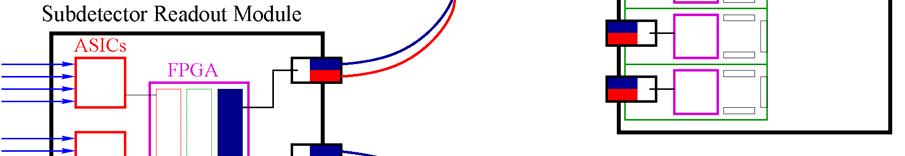
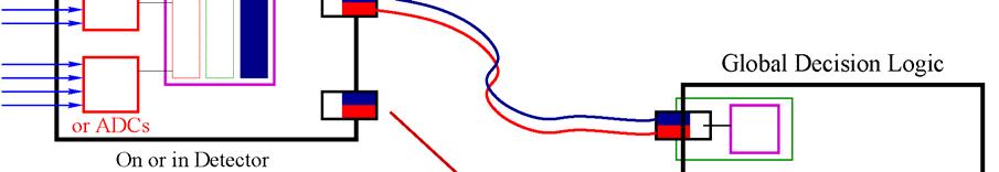
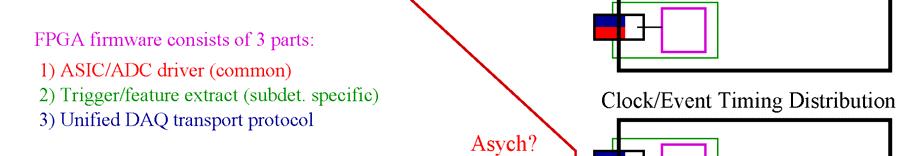
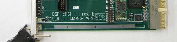


39 mtc Readout 3 DSP_cPCI IRS3B sampling ASIC 12 DAQ fiber transceivers 1,536 channels ch. ASICs 12 SRM board stacks 12 SCROD CAJIPCI clock, trigger, programming g 39
40 Example window buffer mgmt Laser fired randomly with respect to FTSW clock but at a fixed time relative to the global trigger. Example 1: t hit PiLas TrigIn PiLas Fires System Trigger (CAMAC TDC start) 21 MHz FTSW Trigger Issued (CAMAC TDC stop) t FTSW Smaller t hit larger t FTSW 40
41 Understanding Expectations: IRS3B toy Monte Carlo Vpeak Risetime Sampling rate nom dt nom dv 100 ADC 2.7 ns 2.72 Gsa/s ns ADC/sample 40% CFD ratio: Applied between 2 points on leading edge that bracket this transition ssnr = dv/noise Leading Edge time [ns] ~44ps for 100mV peak, 2mV noise 41
Prospect and Plan for IRS3B Readout
 Prospect and Plan for IRS3B Readout 1. Progress on Key Performance Parameters 2. Understanding limitations during LEPS operation 3. Carrier02 Rev. C (with O-E-M improvements) 4. Pre-production tasks/schedule
Commissioning and Initial Performance of the Belle II itop PID Subdetector
 Commissioning and Initial Performance of the Belle II itop PID Subdetector Gary Varner University of Hawaii TIPP 2017 Beijing Upgrading PID Performance - PID (π/κ) detectors - Inside current calorimeter
Waveform Sampling Readout Lessons from the Belle II TOP and applications to future DIRC detectors
 Waveform Sampling Readout Lessons from the Belle II TOP and applications to future DIRC detectors Gary S. Varner University of Hawai i DIRC2017, Castle Rauischholzhausen Overview State-of-the-art DIRC
MCP Signal Extraction and Timing Studies. Kurtis Nishimura University of Hawaii LAPPD Collaboration Meeting June 11, 2010
 MCP Signal Extraction and Timing Studies Kurtis Nishimura University of Hawaii LAPPD Collaboration Meeting June 11, 2010 Outline Studying algorithms to process pulses from MCP devices. With the goal of
KLM: TARGETX. User-Interface for Testing TARGETX Brief Testing Overview Bronson Edralin 04/06/15
 KLM: TARGETX User-Interface for Testing TARGETX Brief Testing Overview Bronson Edralin 1 TARGETX Test Team TARGETX Waveform Sampling/Digitizing ASIC Designer Dr. Gary S. Varner Features 1 GSa/s 16 Channels
Large Area, High Speed Photo-detectors Readout
 Large Area, High Speed Photo-detectors Readout Jean-Francois Genat + On behalf and with the help of Herve Grabas +, Samuel Meehan +, Eric Oberla +, Fukun Tang +, Gary Varner ++, and Henry Frisch + + University
Imaging TOP (itop), Cosmic Ray Test Stand & PID Readout Update
, Cosmic Ray Test Stand & PID Readout Update") Imaging TOP (itop), Cosmic Ray Test Stand & PID Readout Update Tom Browder, Herbert Hoedlmoser, Bryce Jacobsen, Jim Kennedy, KurtisNishimura, Marc Rosen, Larry Ruckman, Gary Varner Kurtis Nishimura SuperKEKB
Imaging TOP (itop), Cosmic Ray Test Stand & PID Readout Update Tom Browder, Herbert Hoedlmoser, Bryce Jacobsen, Jim Kennedy, KurtisNishimura, Marc Rosen, Larry Ruckman, Gary Varner Kurtis Nishimura SuperKEKB
A TARGET-based camera for CTA
 A TARGET-based camera for CTA TeV Array Readout with GSa/s sampling and Event Trigger (TARGET) chip: overview Custom-designed ASIC for CTA, developed in collaboration with Gary Varner (U Hawaii) Implementation:
Sources of Error in Time Interval Measurements
 Sources of Error in Time Interval Measurements Application Note Some timer/counters available today offer resolution of below one nanosecond in their time interval measurements. Of course, high resolution
TOP Overview and itop Detector. G. Varner. Aug. 16, 2016 Belle II Summer PNNL
 TOP Overview and itop Detector G. Varner Aug. 16, 2016 Belle II Summer School @ PNNL CsI(Tl) EM calorimeter: waveform sampling electronics, pure CsI for end-caps Belle II Detector Upgrade 7.4 m RPC m &
Precision testing methods of Event Timer A032-ET
 Precision testing methods of Event Timer A032-ET Event Timer A032-ET provides extreme precision. Therefore exact determination of its characteristics in commonly accepted way is impossible or, at least,
itop (barrel PID) and endcap KLM G. Varner Jan-2011 Trigger/DAQ in Beijing
 and endcap KLM G. Varner Jan-2011 Trigger/DAQ in Beijing") itop (barrel PID) and endcap KLM DAQ Summary G. Varner Jan-2011 Trigger/DAQ in Beijing 1 Overview Update on B-PID (itop) DAQ Big issue is SCROD eklm prototyping: Prototyping status Use Belle2link directly?
itop (barrel PID) and endcap KLM DAQ Summary G. Varner Jan-2011 Trigger/DAQ in Beijing 1 Overview Update on B-PID (itop) DAQ Big issue is SCROD eklm prototyping: Prototyping status Use Belle2link directly?
Eric Oberla Univ. of Chicago 15-Dec 2015
 PSEC4 PSEC4a Eric Oberla Univ. of Chicago 15-Dec 2015 PSEC4 ---> PSEC4a :: overview PSEC4a 6 2-11 GSa/s 256 1024 (or 2048?) 100 (or 200) ns continuous OR 4x (or 8x) 25 ns snapshots [Multi-hit buffering]
MCP Upgrade: Transmission Line and Pore Importance
 MCP Upgrade: Transmission Line and Pore Importance Tyler Natoli For the PSEC Timing Project Advisor: Henry Frisch June 3, 2009 Abstract In order to take advantage of all of the benefits of Multi-Channel
Manual Supplement. This supplement contains information necessary to ensure the accuracy of the above manual.
 Manual Title: 9500B Users Supplement Issue: 2 Part Number: 1625019 Issue Date: 9/06 Print Date: October 2005 Page Count: 6 Version 11 This supplement contains information necessary to ensure the accuracy
GHz Sampling Design Challenge
 GHz Sampling Design Challenge 1 National Semiconductor Ghz Ultra High Speed ADCs Target Applications Test & Measurement Communications Transceivers Ranging Applications (Lidar/Radar) Set-top box direct
How advances in digitizer technologies improve measurement accuracy
 How advances in digitizer technologies improve measurement accuracy Impacts of oscilloscope signal integrity Oscilloscopes Page 2 By choosing an oscilloscope with superior signal integrity you get the
PICOSECOND TIMING USING FAST ANALOG SAMPLING
 PICOSECOND TIMING USING FAST ANALOG SAMPLING H. Frisch, J-F Genat, F. Tang, EFI Chicago, Tuesday 6 th Nov 2007 INTRODUCTION In the context of picosecond timing, analog detector pulse sampling in the 10
BitWise (V2.1 and later) includes features for determining AP240 settings and measuring the Single Ion Area.
 includes features for determining AP240 settings and measuring the Single Ion Area.") BitWise. Instructions for New Features in ToF-AMS DAQ V2.1 Prepared by Joel Kimmel University of Colorado at Boulder & Aerodyne Research Inc. Last Revised 15-Jun-07 BitWise (V2.1 and later) includes features
BitWise. Instructions for New Features in ToF-AMS DAQ V2.1 Prepared by Joel Kimmel University of Colorado at Boulder & Aerodyne Research Inc. Last Revised 15-Jun-07 BitWise (V2.1 and later) includes features
PHOTOTUBE SCANNING SETUP AT THE UNIVERSITY OF MARYLAND. Doug Roberts U of Maryland, College Park
 PHOTOTUBE SCANNING SETUP AT THE UNIVERSITY OF MARYLAND Doug Roberts U of Maryland, College Park Overview We have developed a system for measuring and scanning phototubes for the FDIRC Based primarily on
arxiv: v2 [astro-ph.im] 18 Dec 2015
![arxiv: v2 [astro-ph.im] 18 Dec 2015](/thumbs/72/66999354.jpg "arxiv: v2 [astro-ph.im] 18 Dec 2015") TARGET: toward a solution for the readout electronics of the Cherenkov Telescope Array arxiv:1508.06296v2 [astro-ph.im] 18 Dec 2015 a, J. A. Vandenbroucke b, A. M. Albert a, S. Funk ca, T. Kawashima d,
TARGET: toward a solution for the readout electronics of the Cherenkov Telescope Array arxiv:1508.06296v2 [astro-ph.im] 18 Dec 2015 a, J. A. Vandenbroucke b, A. M. Albert a, S. Funk ca, T. Kawashima d,
MSO-28 Oscilloscope, Logic Analyzer, Spectrum Analyzer
 Link Instruments Innovative Test & Measurement solutions since 1986 Store Support Oscilloscopes Logic Analyzers Pattern Generators Accessories MSO-28 Oscilloscope, Logic Analyzer, Spectrum Analyzer $ The
PicoScope 6407 Digitizer
 YE AR PicoScope 6407 Digitizer HIGH PERFORMANCE USB DIGITIZER Programmable and Powerful 1 GHz bandwidth 1 GS buffer size 5 GS/s real-time sampling Advanced digital triggers Built-in function generator
Comparison Between DRS4 Chip-Based Boards and ADCs for a Flexible PET Electronics
 Comparison Between DRS4 Chip-Based Boards and ADCs for a Flexible PET Electronics D. Stricker-Shaver 1, S. Ritt 2, B. Pichler 1 1 Laboratory for Preclinical Imaging and Imaging Technology of the Werner
Front End Electronics
 CLAS12 Ring Imaging Cherenkov (RICH) Detector Mid-term Review Front End Electronics INFN - Ferrara Matteo Turisini 2015 October 13 th Overview Readout requirements Hardware design Electronics boards Integration
Benefits of the R&S RTO Oscilloscope's Digital Trigger. <Application Note> Products: R&S RTO Digital Oscilloscope
 Benefits of the R&S RTO Oscilloscope's Digital Trigger Application Note Products: R&S RTO Digital Oscilloscope The trigger is a key element of an oscilloscope. It captures specific signal events for detailed
Datasheet SHF A
 SHF Communication Technologies AG Wilhelm-von-Siemens-Str. 23D 12277 Berlin Germany Phone +49 30 772051-0 Fax ++49 30 7531078 E-Mail: sales@shf.de Web: http://www.shf.de Datasheet SHF 19120 A 2.85 GSa/s
PicoScope 6407 Digitizer
 YE AR HIGH PERFORMANCE USB DIGITIZER Programmable and Powerful 1 GHz bandwidth 1 GS buffer size 5 GS/s real-time sampling Advanced digital triggers Built-in function generator USB-connected Signals Analysis
Advanced Test Equipment Rentals ATEC (2832)
") Established 1981 Advanced Test Equipment Rentals www.atecorp.com 800-404-ATEC (2832) This product is no longer carried in our catalog. AFG 2020 Characteristics Features Ordering Information Characteristics
Established 1981 Advanced Test Equipment Rentals www.atecorp.com 800-404-ATEC (2832) This product is no longer carried in our catalog. AFG 2020 Characteristics Features Ordering Information Characteristics
Beam test of the QMB6 calibration board and HBU0 prototype
 Beam test of the QMB6 calibration board and HBU0 prototype J. Cvach 1, J. Kvasnička 1,2, I. Polák 1, J. Zálešák 1 May 23, 2011 Abstract We report about the performance of the HBU0 board and the optical
CAEN Tools for Discovery
 Viareggio March 28, 2011 Introduction: what is the SiPM? The Silicon PhotoMultiplier (SiPM) consists of a high density (up to ~10 3 /mm 2 ) matrix of diodes connected in parallel on a common Si substrate.
PRELIMINARY INFORMATION. Professional Signal Generation and Monitoring Options for RIFEforLIFE Research Equipment
 Integrated Component Options Professional Signal Generation and Monitoring Options for RIFEforLIFE Research Equipment PRELIMINARY INFORMATION SquareGENpro is the latest and most versatile of the frequency
Realizing Waveform Characteristics up to a Digitizer s Full Bandwidth Increasing the effective sampling rate when measuring repetitive signals
 Realizing Waveform Characteristics up to a Digitizer s Full Bandwidth Increasing the effective sampling rate when measuring repetitive signals By Jean Dassonville Agilent Technologies Introduction The
Features. For price, delivery, and to place orders, please contact Hittite Microwave Corporation:
 HMC-C1 Typical Applications The HMC-C1 is ideal for: OC-78 and SDH STM-25 Equipment Serial Data Transmission up to 5 Gbps Short, intermediate, and long haul fiber optic applications Broadband Test and
SLAC National Accelerator Laboratory, CA, USA. University of Hawaii, USA. CEA/Irfu Saclay, France *
 High resolution photon timing with MCP-PMTs: a comparison of a commercial constant fraction discriminator (CFD) with the ASICbased waveform digitizers TARGET and WaveCatcher. D. Breton *, E. Delagnes **,
Digital Delay / Pulse Generator DG535 Digital delay and pulse generator (4-channel)
") Digital Delay / Pulse Generator Digital delay and pulse generator (4-channel) Digital Delay/Pulse Generator Four independent delay channels Two fully defined pulse channels 5 ps delay resolution 50 ps
Digital Delay / Pulse Generator Digital delay and pulse generator (4-channel) Digital Delay/Pulse Generator Four independent delay channels Two fully defined pulse channels 5 ps delay resolution 50 ps
Paul Scherrer Institute Stefan Ritt Applications and future of Switched Capacitor Arrays (SCA) for ultrafast waveform digitizing
 for ultrafast waveform digitizing") Paul Scherrer Institute Stefan Ritt Applications and future of Switched Capacitor Arrays (SCA) for ultrafast waveform digitizing HAP Topic 4, Karlsruhe, Jan. 24th, 2013 Why do we need ultrafast waveform
Paul Scherrer Institute Stefan Ritt Applications and future of Switched Capacitor Arrays (SCA) for ultrafast waveform digitizing HAP Topic 4, Karlsruhe, Jan. 24th, 2013 Why do we need ultrafast waveform
A flexible FPGA based QDC and TDC for the HADES and the CBM calorimeters TWEPP 2016, Karlsruhe HADES CBM
 A flexible FPGA based QDC and TDC for the HADES and the CBM calorimeters TWEPP 2016, Karlsruhe + + + = PaDiWa-AMPS front-end Adrian Rost for the HADES and CBM collaborations PMT Si-PM (MPPC) 27.09.2016
First evaluation of the prototype 19-modules camera for the Large Size Telescope of the CTA
 First evaluation of the prototype 19-modules camera for the Large Size Telescope of the CTA Tsutomu Nagayoshi for the CTA-Japan Consortium Saitama Univ, Max-Planck-Institute for Physics 1 Cherenkov Telescope
The TORCH PMT: A close packing, multi-anode, long life MCP-PMT for Cherenkov applications
 The TORCH PMT: A close packing, multi-anode, long life MCP-PMT for Cherenkov applications James Milnes Tom Conneely 1 page 1 Photek MCP-PMTs Photek currently manufacture the fastest PMTs in the world in
Precise Digital Integration of Fast Analogue Signals using a 12-bit Oscilloscope
 EUROPEAN ORGANIZATION FOR NUCLEAR RESEARCH CERN BEAMS DEPARTMENT CERN-BE-2014-002 BI Precise Digital Integration of Fast Analogue Signals using a 12-bit Oscilloscope M. Gasior; M. Krupa CERN Geneva/CH
A FOUR GAIN READOUT INTEGRATED CIRCUIT : FRIC 96_1
 A FOUR GAIN READOUT INTEGRATED CIRCUIT : FRIC 96_1 J. M. Bussat 1, G. Bohner 1, O. Rossetto 2, D. Dzahini 2, J. Lecoq 1, J. Pouxe 2, J. Colas 1, (1) L. A. P. P. Annecy-le-vieux, France (2) I. S. N. Grenoble,
THE TIMING COUNTER OF THE MEG EXPERIMENT: DESIGN AND COMMISSIONING (OR HOW TO BUILD YOUR OWN HIGH TIMING RESOLUTION DETECTOR )
") THE TIMING COUNTER OF THE MEG EXPERIMENT: DESIGN AND COMMISSIONING (OR HOW TO BUILD YOUR OWN HIGH TIMING RESOLUTION DETECTOR ) S. DUSSONI FRONTIER DETECTOR FOR FRONTIER PHYSICS - LA BIODOLA 2009 Fastest
THE TIMING COUNTER OF THE MEG EXPERIMENT: DESIGN AND COMMISSIONING (OR HOW TO BUILD YOUR OWN HIGH TIMING RESOLUTION DETECTOR ) S. DUSSONI FRONTIER DETECTOR FOR FRONTIER PHYSICS - LA BIODOLA 2009 Fastest
This article appeared in a journal published by Elsevier. The attached copy is furnished to the author for internal non-commercial research and
 This article appeared in a journal published by Elsevier. The attached copy is furnished to the author for internal non-commercial research and education use, including for instruction at the authors institution
16 bit. A digital oscilloscope for the analog world HIGH-RESOLUTION USB OSCILLOSCOPE
 PicoScope 4262 HIGH-RESOLUTION USB OSCILLOSCOPE A digital oscilloscope for the analog world Low noise Two channels 16 MS buffer 16-bit resolution 10 MS/s sampling 5 MHz bandwidth Advanced digital triggers
 Over 5000 VXI cards and mainframes in stock. 1000's of pieces of Test Equipment in stock. Looking for Test Equipment? Visit us on the web at www.recycledequipment.com Recycled Equipment buys, sells, and
BASE-LINE WANDER & LINE CODING
 BASE-LINE WANDER & LINE CODING PREPARATION... 28 what is base-line wander?... 28 to do before the lab... 29 what we will do... 29 EXPERIMENT... 30 overview... 30 observing base-line wander... 30 waveform
FASTFLIGHT-2 Digital Signal Averager. Exceptionally fast LC/TOF-MS or GC/TOF-MS data acquisition... with a simple USB-2 connection to your computer!
 SIGNAL RECOVERY Acquire up to 100 Spectra/second with the 4 GHz FASTFLIGHT-2 Exceptionally fast LC/TOF-MS or GC/TOF-MS data acquisition... with a simple USB-2 connection to your computer! 250 ps interleaved
Generation of Novel Waveforms Using PSPL Pulse Generators
 Generation of Novel Waveforms Using PSPL Pulse Generators James R. Andrews, Ph.D, IEEE Fellow & Bob McLaughlin PSPL Founder & former President (retired) PSPL Sales Engineer Picosecond Pulse Labs (PSPL)
DSM GHz Linear Chirping Source
 DSM202 2.0 GHz GENERAL DESCRIPTION The DSM202 is a linear chirping waveform module that generates two types of chirping waveforms at 32 clocks per frequency update. The DSM202 can be controlled using a
Accuracy Delta Time Accuracy Resolution Jitter Noise Floor
 Jitter Analysis: Reference Accuracy Delta Time Accuracy Resolution Jitter Noise Floor Jitter Analysis Jitter can be described as timing variation in the period or phase of adjacent or even non-adjacent
The TDCPix ASIC: Tracking for the NA62 GigaTracker. G. Aglieri Rinella, S. Bonacini, J. Kaplon, A. Kluge, M. Morel, L. Perktold, K.
 : Tracking for the NA62 GigaTracker CERN E-mail: matthew.noy@cern.ch G. Aglieri Rinella, S. Bonacini, J. Kaplon, A. Kluge, M. Morel, L. Perktold, K. Poltorak CERN The TDCPix is a hybrid pixel detector
BER MEASUREMENT IN THE NOISY CHANNEL
 BER MEASUREMENT IN THE NOISY CHANNEL PREPARATION... 2 overview... 2 the basic system... 3 a more detailed description... 4 theoretical predictions... 5 EXPERIMENT... 6 the ERROR COUNTING UTILITIES module...
BTV Tuesday 21 November 2006
 Test Review Test from last Thursday. Biggest sellers of converters are HD to composite. All of these monitors in the studio are composite.. Identify the only portion of the vertical blanking interval waveform
Study of Timing and Efficiency Properties of Multi-Anode Photomultipliers
 Study of Timing and Efficiency Properties of Multi-Anode Photomultipliers T. Hadig, C.R. Field, D.W.G.S. Leith, G. Mazaheri, B.N. Ratcliff, J. Schwiening, J. Uher, J. Va vra Stanford Linear Accelerator
Front End Electronics
 CLAS12 Ring Imaging Cherenkov (RICH) Detector Mid-term Review Front End Electronics INFN - Ferrara Matteo Turisini 2015 October 13 th Overview Readout requirements Hardware design Electronics boards Integration
ASNT_PRBS20B_1 18Gbps PRBS7/15 Generator Featuring Jitter Insertion, Selectable Sync, and Output Amplitude Control
 ASNT_PRBS20B_1 18Gbps PRBS7/15 Generator Featuring Jitter Insertion, Selectable Sync, and Output Amplitude Control Broadband frequency range from 20Mbps 18.0Gbps Minimal insertion jitter Fast rise and
... A COMPUTER SYSTEM FOR MULTIPARAMETER PULSE HEIGHT ANALYSIS AND CONTROL*
 I... A COMPUTER SYSTEM FOR MULTIPARAMETER PULSE HEIGHT ANALYSIS AND CONTROL* R. G. Friday and K. D. Mauro Stanford Linear Accelerator Center Stanford University, Stanford, California 94305 SLAC-PUB-995
Switching Solutions for Multi-Channel High Speed Serial Port Testing
 Switching Solutions for Multi-Channel High Speed Serial Port Testing Application Note by Robert Waldeck VP Business Development, ASCOR Switching The instruments used in High Speed Serial Port testing are
PicoScope 9300 Series migration guide
 sampling oscilloscopes since 2009 The 9300 Series is a leading-edge product family resulting from a long program of product development. From late 2017, in the process of adding new 15 GHz and 25 GHz models,
Model 7330 Signal Source Analyzer Dedicated Phase Noise Test System V1.02
 Model 7330 Signal Source Analyzer Dedicated Phase Noise Test System V1.02 A fully integrated high-performance cross-correlation signal source analyzer from 5 MHz to 33+ GHz Key Features Complete broadband
Clocking Spring /18/05
 ing L06 s 1 Why s and Storage Elements? Inputs Combinational Logic Outputs Want to reuse combinational logic from cycle to cycle L06 s 2 igital Systems Timing Conventions All digital systems need a convention
PMT Gain & Resolution Measurements in High Magnetic Fields
 PMT Gain & Resolution Measurements in High Magnetic Fields Vincent Sulkosky University of Virginia August 11 th, 2015 SoLID EC Meeting High-B Sensor-Testing Facility 2 The facility was designed for the
For the SIA. Applications of Propagation Delay & Skew tool. Introduction. Theory of Operation. Propagation Delay & Skew Tool
 For the SIA Applications of Propagation Delay & Skew tool Determine signal propagation delay time Detect skewing between channels on rising or falling edges Create histograms of different edge relationships
Tutorial on Technical and Performance Benefits of AD719x Family
 The World Leader in High Performance Signal Processing Solutions Tutorial on Technical and Performance Benefits of AD719x Family AD7190, AD7191, AD7192, AD7193, AD7194, AD7195 This slide set focuses on
ATS MS/s 8-Bit PCI Digitizer
 2 channels sampled at 8-bit resolution 50 MS/s simultaneous real-time sampling rate on each input ±20mV to ±20V input range 256 Kilo samples of on-board acquisition memory per channel AlazarDSO Oscilloscope
Chapter 5 Flip-Flops and Related Devices
 Chapter 5 Flip-Flops and Related Devices Chapter 5 Objectives Selected areas covered in this chapter: Constructing/analyzing operation of latch flip-flops made from NAND or NOR gates. Differences of synchronous/asynchronous
HMC-C060 HIGH SPEED LOGIC. 43 Gbps, D-TYPE FLIP-FLOP MODULE. Features. Typical Applications. General Description. Functional Diagram
 HMC-C Features Typical Applications The HMC-C is ideal for: OC-78 and SDH STM-25 Equipment Serial Data Transmission up to 43 Gbps Digital Logic Systems up to 43 Gbps Broadband Test and Measurement Functional
HP 71910A and 71910P Wide Bandwidth Receiver Technical Specifications
 HP 71910A and 71910P Wide Bandwidth Receiver Technical Specifications 100 Hz to 26.5 GHz The HP 71910A/P is a receiver for monitoring signals from 100 Hz to 26.5 GHz. It provides a cost effective combination
TSG 90 PATHFINDER NTSC Signal Generator
 Service Manual TSG 90 PATHFINDER NTSC Signal Generator 070-8706-01 Warning The servicing instructions are for use by qualified personnel only. To avoid personal injury, do not perform any servicing unless
Techniques for Extending Real-Time Oscilloscope Bandwidth
 Techniques for Extending Real-Time Oscilloscope Bandwidth Over the past decade, data communication rates have increased by a factor well over 10X. Data rates that were once 1Gb/sec and below are now routinely
Clock Jitter Cancelation in Coherent Data Converter Testing
 Clock Jitter Cancelation in Coherent Data Converter Testing Kars Schaapman, Applicos Introduction The constantly increasing sample rate and resolution of modern data converters makes the test and characterization
Introduction. NAND Gate Latch. Digital Logic Design 1 FLIP-FLOP. Digital Logic Design 1
 2007 Introduction BK TP.HCM FLIP-FLOP So far we have seen Combinational Logic The output(s) depends only on the current values of the input variables Here we will look at Sequential Logic circuits The
A High-Resolution Flash Time-to-Digital Converter Taking Into Account Process Variability. Nikolaos Minas David Kinniment Keith Heron Gordon Russell
 A High-Resolution Flash Time-to-Digital Converter Taking Into Account Process Variability Nikolaos Minas David Kinniment Keith Heron Gordon Russell Outline of Presentation Introduction Background in Time-to-Digital
Scintillation Tile Hodoscope for the PANDA Barrel Time-Of-Flight Detector
 Scintillation Tile Hodoscope for the PANDA Barrel Time-Of-Flight Detector William Nalti, Ken Suzuki, Stefan-Meyer-Institut, ÖAW on behalf of the PANDA/Barrel-TOF(SciTil) group 12.06.2018, ICASiPM2018 1
SELECTION GUIDE Series of RF and Universal Frequency Counter/Timers
 SELECTION GUIDE 53200 Series of RF and Universal Frequency Counter/Timers With the Keysight Technologies, Inc. 53200 RF and Universal Frequency Counters/Timers, You Get: More bandwidth 350 MHz baseband
Experiment 7: Bit Error Rate (BER) Measurement in the Noisy Channel
 Measurement in the Noisy Channel") Experiment 7: Bit Error Rate (BER) Measurement in the Noisy Channel Modified Dr Peter Vial March 2011 from Emona TIMS experiment ACHIEVEMENTS: ability to set up a digital communications system over a noisy,
Experiment 7: Bit Error Rate (BER) Measurement in the Noisy Channel Modified Dr Peter Vial March 2011 from Emona TIMS experiment ACHIEVEMENTS: ability to set up a digital communications system over a noisy,
THE WaveDAQ SYSTEM FOR THE MEG II UPGRADE
 Stefan Ritt, Paul Scherrer Institute, Switzerland Luca Galli, Fabio Morsani, Donato Nicolò, INFN Pisa, Italy THE WaveDAQ SYSTEM FOR THE MEG II UPGRADE DRS4 Chip 0.2-2 ns Inverter Domino ring chain IN Clock
Synthesized Clock Generator
 Synthesized Clock Generator CG635 DC to 2.05 GHz low-jitter clock generator Clocks from DC to 2.05 GHz Random jitter
Electrical and Electronic Laboratory Faculty of Engineering Chulalongkorn University. Cathode-Ray Oscilloscope (CRO)
") 2141274 Electrical and Electronic Laboratory Faculty of Engineering Chulalongkorn University Cathode-Ray Oscilloscope (CRO) Objectives You will be able to use an oscilloscope to measure voltage, frequency
2141274 Electrical and Electronic Laboratory Faculty of Engineering Chulalongkorn University Cathode-Ray Oscilloscope (CRO) Objectives You will be able to use an oscilloscope to measure voltage, frequency
SV1C Personalized SerDes Tester
 SV1C Personalized SerDes Tester Data Sheet SV1C Personalized SerDes Tester Data Sheet Revision: 1.0 2013-02-27 Revision Revision History Date 1.0 Document release Feb 27, 2013 The information in this
High ResolutionCross Strip Anodes for Photon Counting detectors
 High ResolutionCross Strip Anodes for Photon Counting detectors Oswald H.W. Siegmund, Anton S. Tremsin, Robert Abiad, J. Hull and John V. Vallerga Space Sciences Laboratory University of California Berkeley,
Expect to Make Waves.
 Expect to Make Waves. The New Oscilloscope Large 10.4" LCD touch screen Long capture time Extensive communication capabilities www.lecroy.com The New Oscillos From its large 10.4" LCD touch screen to its
Synchronizing Multiple ADC08xxxx Giga-Sample ADCs
 Application Bulletin July 19, 2010 Synchronizing Multiple 0xxxx Giga-Sample s 1.0 Introduction The 0xxxx giga-sample family of analog-to-digital converters (s) make the highest performance data acquisition
EL302 DIGITAL INTEGRATED CIRCUITS LAB #3 CMOS EDGE TRIGGERED D FLIP-FLOP. Due İLKER KALYONCU, 10043
 EL302 DIGITAL INTEGRATED CIRCUITS LAB #3 CMOS EDGE TRIGGERED D FLIP-FLOP Due 16.05. İLKER KALYONCU, 10043 1. INTRODUCTION: In this project we are going to design a CMOS positive edge triggered master-slave
PEP-II longitudinal feedback and the low groupdelay. Dmitry Teytelman
 PEP-II longitudinal feedback and the low groupdelay woofer Dmitry Teytelman 1 Outline I. PEP-II longitudinal feedback and the woofer channel II. Low group-delay woofer topology III. Why do we need a separate
Low Level RF for PIP-II. Jonathan Edelen LLRF 2017 Workshop (Barcelona) 16 Oct 2017
 16 Oct 2017") Low Level RF for PIP-II Jonathan Edelen LLRF 2017 Workshop (Barcelona) 16 Oct 2017 PIP-II LLRF Team Fermilab Brian Chase, Edward Cullerton, Joshua Einstein, Jeremiah Holzbauer, Dan Klepec, Yuriy Pischalnikov,
Low Level RF for PIP-II Jonathan Edelen LLRF 2017 Workshop (Barcelona) 16 Oct 2017 PIP-II LLRF Team Fermilab Brian Chase, Edward Cullerton, Joshua Einstein, Jeremiah Holzbauer, Dan Klepec, Yuriy Pischalnikov,
Table. J. Va vra,
 J. Va vra, 7.12.2006 Table - Charge distribution spread in anode plane - Size of MCP holes - MCP thickness - PC-MCP-IN and MCP-OUT-anode gaps - Pad size and the grid line width - Photocathode choice 1
PCI-DAS6034, PCI-DAS6035, and PCI-DAS6036
 PCI-DAS6034, PCI-DAS6035, and PCI-DAS6036 Specifications Document Revision 1.2, February, 2010 Copyright 2010, Measurement Computing Corporation Typical for 25 C unless otherwise specified. Specifications
7000 Series Signal Source Analyzer & Dedicated Phase Noise Test System
 7000 Series Signal Source Analyzer & Dedicated Phase Noise Test System A fully integrated high-performance cross-correlation signal source analyzer with platforms from 5MHz to 7GHz, 26GHz, and 40GHz Key
RX40_V1_0 Measurement Report F.Faccio
 RX40_V1_0 Measurement Report F.Faccio This document follows the previous report An 80Mbit/s Optical Receiver for the CMS digital optical link, dating back to January 2000 and concerning the first prototype
Two Channel PC Oscilloscopes with Arbitrary Waveform Generator OMSP-2000 Series
 Two Channel PC Oscilloscopes with Arbitrary Waveform Generator OMSP-2000 Series U 10 to 25 MHz Bandwidths U Up to 200 MS/s Sampling Rate U Advanced Digital Triggers U Persistence Display Modes U Mask Limit
Performance of the MCP-PMT for the Belle II TOP counter
 Performance of the MCP-PMT for the Belle II TOP counter Kodai Matsuoka (KMI, Nagoya Univ.) S. Hirose, T. Iijima, K. Inami, Y. Kato, Y. Maeda, R. Mizuno, Y. Sato, K. Suzuki (Nagoya Univ.) TOP (Time Of Propagation)
Analog to Digital Conversion
 Analog to Digital Conversion What the heck is analog to digital conversion? Why do we care? Analog to Digital Conversion What the heck is analog to digital conversion? Why do we care? A means to convert
Conceps and trends for Front-end chips in Astroparticle physics
 Conceps and trends for Front-end chips in Astroparticle physics Eric Delagnes Fabrice Feinstein CEA/DAPNIA Saclay LPTA/IN2P3 Montpellier General interest performances Fast pulses : bandwidth > ~ 300 MHz
MAHARASHTRA STATE BOARD OF TECHNICAL EDUCATION (Autonomous) (ISO/IEC Certified)
 (ISO/IEC Certified)") Important Instructions to examiners: 1) The answers should be examined by key words and not as word-to-word as given in the model answer scheme. 2) The model answer and the answer written by candidate
Important Instructions to examiners: 1) The answers should be examined by key words and not as word-to-word as given in the model answer scheme. 2) The model answer and the answer written by candidate
Design and Performance of an Automated Production Test System for a 20,000 channel single-photon, sub-nanosecond large area muon detector
 Design and Performance of an Automated Production Test System for a 20,000 channel single-photon, sub-nanosecond large area muon detector A Thesis submitted to the graduate division of the University of
DDA-UG-E Rev E ISSUED: December 1999 ²
 7LPHEDVH0RGHVDQG6HWXS 7LPHEDVH6DPSOLQJ0RGHV Depending on the timebase, you may choose from three sampling modes: Single-Shot, RIS (Random Interleaved Sampling), or Roll mode. Furthermore, for timebases
Comparison of NRZ, PR-2, and PR-4 signaling. Qasim Chaudry Adam Healey Greg Sheets
 Comparison of NRZ, PR-2, and PR-4 signaling Presented by: Rob Brink Contributors: Pervez Aziz Qasim Chaudry Adam Healey Greg Sheets Scope and Purpose Operation over electrical backplanes at 10.3125Gb/s
Report on 4-bit Counter design Report- 1, 2. Report on D- Flipflop. Course project for ECE533
 Report on 4-bit Counter design Report- 1, 2. Report on D- Flipflop Course project for ECE533 I. Objective: REPORT-I The objective of this project is to design a 4-bit counter and implement it into a chip