Smart encoders & actuators
|
|
|
- Steven Francis
- 6 years ago
- Views:
Transcription


1 Smart encoders & actuators Incremental & absolute rotary encoders, heavy-duty, bearingless and feedback 2013
2
3


.")


4 ROTAPULS Incremental rotary encoders ROTACOD Absolute rotary & Fieldbus encoders ROTAMAG Rotary Magnetic encoder & Encoder modules LINEPULS LINECOD Linear Absolute & Incremental encoders DRAW-WIRE Draw-wire encoders & potentiometers COUPLINGS Flexible & Transmission couplings POSICONTROL Displays & Signal converters Encoder Interfaces DRIVECOD Rotary Actuators & Positioning units 1982 Lika Electronic founded in Schio (VI) Manufacturing of absolute encoders with integrated display and incremental encoders for the Italian market Foundation of Lika Trading commercial corporate Lika Electronic is the first company in Italy to offer a complete portfolio of encoders in the 58 mm diam. range Lika is first certified to ISO 9001: Lika numbers 8 customers Lika starts the production of absolute encoders for the German market Lika produces a 50 mm diameter miniature encoder, the smallest absolute encoder in Europe The 100,000th encoder rolled off the production line ROTACAM ASR58 is the first absolute encoder fitted with integrated cam programmer. 4 Specifications subject to changes without prior notice


5 An international family company, corporate profile Lika Electronic stands for encoders and position measuring systems. Since its inception in 1982, Lika Electronic develops and manufactures incremental and absolute, optical and magnetic, rotary and linear encoders, incremental & absolute sensors, linear and rotary incremental & absolute magnetic measurement systems, rotary actuators, displays, signal converters and encoder interfaces. Starting as a family-owned business, thanks to its technical competence and comprehensive know-how in the automation industry along with the high quality standards and the skill in providing solutions that target specific customer needs, over the years Lika Electronic has grown becoming a forward thinking innovative and global company among the leading manufacturers of optical encoders and magnetic measurement systems in Europe and worldwide. Many key features include the extensive technical engineering skills, in-depth knowledge and expertise in digital and analogical electronic design as well as the proven daily practice in co-operation with universities, research institutions and customers in order to develop and provide advanced electronic equipment and high-tech materials & devices tailored to specific customer and market requirements. Moreover software development and mechanical & optical components design are entirely performed within the company. Production machinery and tools are often engineered and built internally to satisfy specific needs and performances. Every day Lika Electronic is committed to being a step ahead and always at the forefront of innovation, looking to the future with the enthusiasm that steers the company towards new opportunities without giving up the strength of being an international family company. Lika Electronic is certified for compliance with ISO 9001:2008 quality management system and is now committed to adopt an environmental management system complying with ISO 14001:2004 requirements. All Lika products are designed and manufactured to fully meet the requirements of CE, RoHS and REACH directives, most of them are UL and CSA compliant too. ATE certified solutions suitable to be integrated into potential explosive environments and hazardous areas are also available. Global presence, make us closer to the customer Every day, everywhere Lika Electronic works in close contact with its customers to build strong, long-lasting relationships and support them at all times in each day-to-day requirement. Lika s actions focus on customers needs with daily challenges to develop reliable and cutting edge solutions. Continuous innovation, outstanding expertise, overall quality, prompt action and maximum flexibility are the fundamental values that Lika Electronic is truly proud of offering its customers when working together. Lika Electronic operates all over the world providing a widespread and efficient global distribution network, offering unrivalled technical support and excellent customer service. At the present time the export share is approximately 60% of the turnover in more than 50 countries First 16-bit resolution single-turn absolute encoder engineered for installation in aerostatic probes developed by Florence University ROSETTA space probe project gets under way in co-operation with CISAS Production in antistatic environment (ESD). DRIVECOD & POSICONTROL product ranges are launched in the market Lika Electronic celebrates its 25th anniversary with a series of special events th anniversary: 30 new products for our 30 years event launched Lika Electronic moves its corporate headquarters to Carrè (VI) establishing in new larger production and office premises Foundation of Lika subsidiary in Germany Arianne 5 rocket successfully launched: Rosetta probe fits Lika encoders ALMA project: giant array of 12-m radio telescopes equipped with special custommade Lika encoders Lika introduces the innovative range of heavy-duty products dedicated to steel & iron industry and wind mills. 5


6 Environmental policies at Lika Electronic Besides a daily investment in materials research, electronics improvement and software development, day after day also environmental values have become an unavoidable commitment in each choice and strategy of the company. For this purpose, even though discretionary, conscious about the importance of the human health, the environmental protection and the preservation of natural resources, since 2006 Lika Electronic has decided to fully comply with the directive 2002/95/ EC, usually referred to as RoHS, i.e. Restriction of Hazardous Substances Directive; and two years later Lika Electronic has adhered to stringent directive 1907/2006/EC, usually referred to as REACH, banning the chemical substances reported in ECHA s Candidate List and in authorized list. Now Lika Electronic is committed to adopt an environmental management system complying with ISO 14001:2004 requirements in order to promote a responsible environmental policy among employees, suppliers and customers as well. Dedication to corporate responsibility has recently led the company to implement a new real green investment for environmental sustainability: Lika Electronic is now equipped with a photovoltaic system consisting of 260 PV modules for a maximum power output of about 65 kw which prevents the emission of approximately 40 tonnes of CO 2 per year. Customer service & assistance Production and manufacturing processes from design to after-sales are constantly monitored and improved to ensure optimized, fast, resilient and cost-effective service. Thus you can trust in a dependable and on-time service -from production to delivery. Furthermore Lika Electronic is able to translate the customers specific requirements and needs into customized solutions in very short time, both in small and large batches. A repairs workshop also operates within Lika s facilities where expert and thorough personnel provides fast and effective repair service guaranteeing reduced times and costs. Lika s team is dynamic, professional and customer-focused and has relevant experience and technical competence. Whether you need troubleshooting assistance or business advice it provides outstanding and responsive technical support and excellent customer service. English, Italian, German, French and Spanish are fluently spoken. Offices and phone lines are open Monday to Friday 8am 5pm CET. Preferential items & express service Lika Electronic provides more flexibility and faster action as all design and production processes are carried out in-house. For this reason we are able to translate any needs into customized solutions in very short time. Fast manufacturing service is available on and intended to ensure production within 3 working days only. The service is subject to availability of all parts at our premises. Furthermore for our best selling encoders and configurations we offer a range of Preferential items. These are usually disposable on stock thus they can be often dispatched the same day, otherwise very short delivery time is guaranteed. When available, preferential items and configurations are listed in the datasheets. Position measurement & control Smart encoders & actuators? Catalogues, user manuals and website As a part of Lika s ongoing commitment to provide the highest level of support to make customers job easier, a full set of technical and commercial documentation is easily available in our corporate website and upon request. Catalogues, brochures, data sheets, user s manuals and installation guides are offered in the most common languages. The general catalogue is a hands-on reference guide useful to describe the whole products portfolio and is available in more than 10 languages. While series-specific and thematic catalogues provide detailed product information and technical specifications that can help you always make the right choice. General catalogue 2013 Products for the wind generator industry 6
7 Quality policies at Lika Electronic Quality policy has always been of highest priority for Lika Electronic. Lika is every day committed to develop and manufacture products that are recognized by customers and the industry for their high quality and performances. Quality policy statement has been established since 1997 when Lika Electronic was first certified to ISO 9001:1994. Nowadays Lika Electronic is certified to ISO 9001:2008 compliant quality management system. It attests that Lika Electronic places the utmost importance in the quality, safety and reliability of its products and every day aims at ensuring the full satisfaction of customer s needs. This is achieved by continuously developing new products that implement the most updated technologies and can easily meet customers and markets requirements; by enhancing both internal and suppliers processes for continual improvement of the system and the assurance of conformity; and by always meeting the regulations and complying early with future standards. All production and manufacturing processes as well as company management activities are involved in quality assurance and enhancement: from purchasing to goods receipt, from manufacturing to technical, from sales to account departments. With the same purpose and even if not binding with this directive, Lika Electronic is committed to comply with Directive 1907/2006/EC, usually referred to as REACH. REACH is the European Community Regulation on chemicals and their safe use. It deals with the Registration, Evaluation, Authorization and Restriction of Chemical substances. The law entered into force on 1 June The aim of REACH is to improve the protection of human health and the environment through the better and earlier identification of the intrinsic properties of chemical substances and progressive substitution of the most dangerous chemicals when suitable alternatives have been identified. All Lika encoders are CE compliant and fully meet the requirements of the EMC European Directives as well as the recent Directive 2011/65/EU (RoHS2). Most of the products from Lika Electronic bear the c-ru-us certification mark. The c-ru-us mark is a certification mark issued by Underwriters Laboratories stipulating that Lika encoders meet the requirements for the US (UL) standard (designated by the us ) and the Canadian (CSA) standard (designated by the c ). They are listed under the files available on request. All Lika encoders comply with the Directive 2002/95/EC, usually referred to as RoHS, i.e. Restriction of Hazardous Substances Directive, since The RoHS directive aims to restrict certain dangerous substances commonly used in electronic equipment. Any RoHS compliant component is attested to be free from the presence of Lead (Pb), Cadmium (Cd), Mercury (Hg), Hexavalent chromium (Hex-Cr), Polybrominated biphenyls (PBB), and Polybrominated diphenyl ethers (PBDE). This means that in all Lika products maximum concentrations of the afore-mentioned substances are under the restrictive limits permitted by this Directive. July 2011 the new Directive 2011/65/EU, sometimes referred to as RoHS2, was published by the European Commission. The main point to consider is that the RoHS directive is now a CE-marking Directive. This means that compliance with RoHS Directive is required in order to place the CE mark on any product. Lika Electronic declares that all products are here and now RoHS2 compliant and therefore they are allowed to bear the CE mark. Compliance with the ATE Directive 94/9/EC is a legal requirement in all European Union Member States for any equipment intended for use in potentially explosive atmospheres. Lika Electronic designs and manufactures a full range of ATE certified encoders in both incremental and absolute versions. For more information on ATE certified encoders refer to page 13 7


8 WEEE and batteries disposal information Directive 2012/19/UE (as previous 2002/96/EC) is intended, as a first priority, to prevent waste electric and electronic equipment (hence the acronym WEEE) from being introduced into the unsorted waste stream; and in addition to promote reuse, recycling and other forms of recovery of such wastes so as to reduce the disposal of waste. Furthermore it encourages the ecological design and production of electrical and electronic equipment which take into account and facilitate dismantling and recovery, in particular the re-use and recycling of WEEE, their components and materials. Extended producer and user responsibility for separate collection is the precondition to ensure specific treatment and recycling of WEEE and is necessary to achieve the chosen level of protection of human health and the environment. Products manufactured by Lika Electronic are not covered by WEEE directive currently as they do not fall under the categories coming within the scope of the Directive. WEEE directive applies to standalone products; our products cannot function entirely on their own, are always integrated into larger systems and come as part of complex equipment. Lika Electronic is working every day to achieve full compliance with both RoHS and REACH directives; and in accordance with them it has decided to ban from the whole range of products the use of batteries containing mercury, lead and cadmium. Aside from this, electric and electronic equipment and batteries may anyway contain materials, components and substances which can be dangerous to the environment and harmful to human health if not disposed properly. So you should not dispose of electrical and electronic equipment and batteries as unsorted municipal waste. Please we advise you to dispose of waste so as to reduce environmental impact and increase re-use, recycling and recovering of WEEE. For this reason the symbol of the crossed-out wheelie bin appears in the documentation of all our products. For customers who wish to send us back Lika products at end of their life, we are willing to recycle and dispose of them in compliance with Directives and regulations in force. Quality & warranty sticker Lika Electronic is every day committed at ensuring the maximum quality, reliability and durability of its products. Thus production and manufacturing processes are constantly monitored and improved to provide optimized, fast, resilient and cost-effective solutions. Competent and skilled teamwork is further the key to achieve innovative and safe products that fully meet the customers expectations. Compliance with the strict quality requirements which guide each daily action and decision of Lika is proved by the Quality & Warranty Seal of Approval applied to each product before leaving the premises. It attests that each product has been manufactured, verified and tested individually by expert and thorough personnel having relevant experience and technical competence; furthermore it certifies that the product has been subjected to rigorous testing throughout its development and production in order to assess its safety, performance and conformity to Lika s quality standards. 8

9 ROTAPULS ROTACOD Technical information Rotary encoders A rotary encoder is an electro-mechanical device (transducer) specifically designed to translate the motion of a rotary axis, i.e. a rotary mechanical movement such as the one of a motor or a shaft, into either analogue/digital electrical signals or a digital code. In this way, using appropriate electronic equipment the encoder can provide information about travel, position, displacement, direction, velocity and acceleration. An encoder can be found in the widest variety of industrial sectors, wherever a motor is installed or a motion is generated, such as in automotive, wood, paper, steel, aerospace and chemical industries, robotics, lifts and cranes, painting machines, packaging machinery, mechanical engineering, conveyors, among others. And each application needs its very own solution that has to be uniquely suitable for specific aims. Automotive, aerospace and packaging industries need flexibility, high processing speed and absolutely safe and reliable signal transmissions; harsh environments affected by oil, dirt, dust, moisture as well as severe temperature fluctuations require rugged and high protection rate encoders; wood, paper and steel industries demand robust encoders capable of withstanding both high mechanical loadings and extreme shock and vibration levels; the use in hazardous areas such as on painting machines, chemical plants, petrol refineries and laboratories, off-shore platforms and fertiliser plants imposes the installation of ATE certified equipment. The proper solution for each and all applications. The following technical notes are intended to help you evaluate our products and always make the right choice. Rotary encoders can be either incremental or absolute. Most of the incremental encoders produce square waves signals but also sinusoidal signals and can provide travel, position, displacement and velocity information; positional information is relative, this means that it is possible to know both if the axis is rotating and if it is rotating clockwise or counterclockwise; but it is not possible to gather information about the absolute position of the axis. For this reason the homing operation is always required at the beginning of the process to determine the absolute position of the system (detection of the reference point or zero point). Information is expressed in pulses per revolution (PPR). Incremental encoder An absolute encoder is designed to output the absolute position information; it has a unique code pattern, thus it can provide a unique digital code for each angular position of the axis. The main feature is that it is always possible to know exactly the position of the axis. For instance, if you turn off the power supply and move the encoder shaft or the device, then at power on the absolute encoder will output the current position of the axis precisely. This means that no homing operation is required to determine the absolute position. An absolute encoder provides to the motion control a digital code that can be in pure Binary, Gray or BCD output code format. Customarily it is equipped with parallel or serial (SSI, BISS, etc.) output circuits, but can afford almost all fieldbus interfaces available on the market. Absolute encoders can be either single-turn or multi-turn. Single-turn encoders provide the absolute position information per each revolution and the counting operation resumes again after each revolution; thus the resolution of the encoder is the number of information per turn (typically expressed in counts per revolution -cpr-, otherwise information per revolution). While multi-turn encoders provide standard absolute information, but rely upon an additional internal counting process to monitor and track the number of rotations: in this way multiple revolutions can be performed before restarting the counting operation. This results in a double resolution (typically expressed in overall bits): the absolute position per each revolution and the information on the number of revolutions. The overall information is univocal. Absolute encoder 9
10 ROTAPULS ROTACOD Technical information Products by category, products by application Lika products are research-driven and designed to set the standards. They all apply the latest state-of-the-art technologies and aim at meeting early the everchanging requirements of customers and markets. Dependability, high quality and innovative strength are part of each one of them. Encoders and actuators, sensors and interfaces, they only fit selected advanced components and are inspected individually before delivery, ensuring they can operate safely and reliably throughout the lifetime of any application. Nevertheless these basic properties need to be carefully balanced as not all are suitable for specific requirements in the same manner. Lika products are practice-based and customer-oriented and are born out of its proven experience and expertise. For this reason Lika Electronic can offer a wide products portfolio devised for many application and operating environments. And this is why the products listed in this catalogue are divided into five main categories according to their specialized application: light-duty, industrial, feedback, heavy-duty, ATE. Light-duty encoders are used in light industrial and laboratory applications. The working environment is generally neat and tidy while temperature, moisture and dirt conditions are controlled. They are not affected neither by mechanical tensions nor by chemical agents or relevant temperature fluctuations. For these reasons they have low-medium IP-rated environmental protection. On the other hand they need to be versatile and offer a large variety of both mechanical and electrical interfaces (flexible mounting possibilities for both solid and hollow shaft versions, several output circuits and even fieldbus interfaces). Light-duty encoders Incremental: Absolute: Recommended types I28, MI36-MC36, MI36K I40-I41, CK41-CK46 MS36-MSC36, MM36-MMC36 Light-duty encoders are offered in several versions providing: incremental and absolute information optical and magnetic technology solid and hollow shaft mechanical interfaces compact dimensions Application: electronic assembly systems semiconductor industry printing, labelling & graphical machinery measuring machinery electro-medical instruments office automation Bearingless: IM30-IM31-IM56 10

11 ROTAPULS ROTACOD Technical information Industrial category is the most versatile and is intended to target the widest requirements of industrial and motion control markets. Because of a large variety of applications, industrial encoders need to be highly flexible and even multi-purpose, thus they offer several features; furthermore they must strike a careful balance between providing adequate protection against harsh industrial conditions and ensuring high speeds and accuracies as well as absolute safe signal transmissions. Industrial products boast a rugged design and high-protection standards with immunity to dirt, debris and environmental factors and are able to handle high shock and vibration impacts as well as large temperature fluctuations. Their high quality and outstanding dependability are exemplified by performance with maximum accuracy at highest speeds, in a full range of industrial network connections. Industrial encoders Recommended types Almost all types with some restrictions on light duty and bearingless encoders. Series with Ø58mm are the most recommended. Industrial encoders are offered in several versions providing: Incremental and absolute information additional incremental / absolute tracks optical and magnetic technology solid and hollow shaft versions several fieldbus interfaces increased IP protection rate Application: packaging machinery food & beverage industry metal & plastic working machinery woodworking machinery stone & marbles working machinery pharmaceutical textiles machinery robotics and product handling equipment elevators Feedback encoders are specifically designed for position feedback of electric motors. Thus they encompass standard interfaces suited to both communication and data exchange and mechanical installation in order to meet the requirements of a wide range of feedback applications. As they are installed in motor shaft they usually have small dimensions and in particular minimal depth; they are available in both solid and hollow shaft versions, anyway hollow shaft encoders are more compact, while solid shaft encoders are bigger and need flexible couplings, fixing clamps, adapting flanges or mounting bells for installation. Developed to meet critical requirements although IP protection rate is not necessarily high, they are able to handle high temperatures and speeds and boast excellent accuracy, safe signal transmission and high counting frequencies. Some of them feature insulated bearings protected against eddy currents and interface immunity. Feedback encoders Incremental: Absolute: Bearingless: Recommended types C50, CB50, CB59-CB60, C80, C81, C82 AS36-ASC36, AM36-AMC36, HS58 series HM58 series, HSCT, HMCT IM30-IM31-IM56, SGSM-SGSD MIK36-MSK36, SMRI Feedback encoders are offered in several versions providing: Incremental and absolute information absolute single-turn and multi-turn versions additional incremental / absolute tracks bearingless construction solid and hollow shaft mechanical interfaces highest resolutions Application: general purpose electric motors (AC and DC) closed loop stepper motors brushless motors, servomotors, etc. rotary and linear generic applications 11


12 ROTAPULS ROTACOD Technical information The harshest and most critical environments affected by oil, grease, dirt, the finest of dust particles, moisture, water jets, wash down cleaning, high pressure steam, common chemical agents as well as severe temperature fluctuations require rugged and high protection level encoders. Heavy-duty encoders are designed for the toughest applications and built to last. They are robust and capable of withstanding both highest mechanical loadings and extreme shock and vibration levels as they fit selected components and increased size ball bearings. They feature reliable design, sturdy construction and hermetically sealed housing for dependable enduring service. Furthermore they are designed to offer outstanding reliability and absolute safety, with little or no maintenance. Usually they are devised for applications that demand high accuracy, therefore they encompass superior features. Heavy-duty encoders Incremental: Absolute: Bearingless: Recommended types C77, C81, I115, I116, C100, C101 I70, ICS MH58S, AC77, AC77 FB SGSM-SGSD, SMRI Heavy-duty encoders are offered in several versions providing: incremental and absolute information absolute single-turn and multi-turn versions additional incremental / absolute tracks optical and magnetic technology cable and connector versions extra robust housing increased size ball bearings highest IP protection rate Application: ore mills, steel mills and metallurgic plants cranes, hoists and lifting equipment die casting industry aerospace industry utility vehicles and mobile equipment wind power plants marine industry and off-shore plants harbour equipment wood, paper and metal working industries

13 ROTAPULS ROTACOD Technical information Compliance with the ATE Directive 94/9/EC is a legal requirement in all European Union Member States for any equipment intended for use in potentially explosive atmospheres. Lika Electronic designs and manufactures a comprehensive range of ATE certified encoders in both incremental and absolute versions suitable to be integrated into applications in hazardous areas such as in mining industry, surface industry, chemical plants, petrol refineries and laboratories, painting machines, enamelling machines, fertiliser plants, food industry, off-shore platforms, ATE motors and ATE elevators. In such environments and applications where fire or explosion hazards may exist due to flammable gases, vapours or liquids (such as hydrocarbons, solvents, varnishes, diluent, gas, alcohol, dyes, perfumes, chemical products, agents for manufacture of plastics, etc.), combustible dust or powders as well as ignitable fibres or flyings (such as magnesium, aluminium, sulphur, cellulose, cereals, carbon, wood, milk, resins, sugars, starch, polystyrenes, fertilizer, etc.), equipments must be safe against high temperatures, sparks, arcs and electrical phenomena. Furthermore the enclosure must be strong enough to contain an explosion within and to withstand everyday use in the most demanding conditions. ATE certified encoders all provide airtight and flameproof enclosures and high ignition protection levels against both gas and dust explosive atmospheres and are intended for use in Zones 1, 2, 21 and 22 and in the temperature category T6. Please note that the higher is the protection rate and the lower is the external surface maximum temperature, less the encoder may become source of explosion and ignition. Lika encoders bear the following ATE marking: II 2GD Ex d IIC T6, Ex td A21 IP65 T85 C This means that they can be used in environments where explosive atmosphere can happen (group II), provide high level of protection for both gas and dust explosive atmospheres (2GD) and fit an explosion-proof casing (Ex d) against the most dangerous gases group (IIC: hydrogen and acetylene) with maximum surface temperatures below 85 C (T6). Furthermore, in particular about dust, their casing is dust-proof with IP65 protection rate so explosive dust cannot penetrate inside the encoder (Ex td IP65) and their external surface cannot reach a temperature higher than 85 C. ATE certified encoders are suitable for use in Zones 1, 2, 21, 22; Zones 1 and 21 refer to areas in which an explosive mixture of air and flammable substances in form of gas (1) or dust (21) is likely to occur in normal operation; while the lower level zones 2 and 22 refer to areas in which an explosive mixture of air and flammable substances in form of gas (2) or dust (22) is not likely to occur in normal operation and if it occurs it will persist only for a short time. ATE encoders are offered in the following versions providing: incremental and absolute information absolute multi-turn version optical technology hollow shaft mechanical interface several fieldbus interfaces Application: mining industry surface industry chemical plants, petrol refineries and laboratories painting machines enamelling machines fertiliser plants food industry off-shore platforms ATE-motors, ATE-elevators ATE certified encoders Recommended types Incremental: Absolute: C77 AC77 13

14 ROTAPULS ROTACOD Technical information Lika Electronic offers a varied range of industrial, miniature and fieldbus stainless steel encoders suitable to meet the severe requirements of the food & beverage industry as well as to withstand the most aggressive and tricky operating environments such as in chemical and petrochemical industry, mobile equipment, marine installations, pharmaceutical, medical and surgical applications. Hygiene, safety and security requirements are particularly stringent in the food and beverage industry. Companies in this sector need to comply with very severe regulations which impose the highest demands on the quality, safety and durability of materials and equipment. Materials must be first-rate, tough and resistant to corrosion and salt as well as to cleaning agents and chemical contaminants; furthermore they must often cope with the rigours of continuous sanitary wash down and sterilisation processes, even at high temperatures. Equipment must be built-to last and needs to be cleaned easily and quickly to avoid harmful substances to accumulate, thus a high degree of protection is necessarily required. A comprehensive line of Lika Electronic s incremental and absolute encoders is offered with AISI 410 stainless steel enclosure and specific increased characteristics to meet such hard requirements. They all feature stainless steel frame, flange and shaft with specific hygiene design and smooth and paint-free finish which ensure exceptional resistance to corrosion and antibacterial properties and avoid trapped contaminants. In addition they mount rugged long-lasting bearings protected in a stainless steel housing for enhanced encapsulation. This results in a high-rated IP protection (IP65/IP67) and excellent durability under extreme conditions and temperatures (both high and low). Also connectors and cables are expressly intended to deal with chemical exposure and frequent aggressive cleaning; their materials specifically suit the demands of food processing applications. Furthermore all exposed materials are selected to be non-toxic and safe for contact with edible products. The encoder range for food and beverage industry comes in both incremental and absolute versions and a variety of construction features, interfaces and functions to cover multiple areas of application. Special stainless steel encoders for food & beverage industry Incremental: Absolute: Recommended types MI36K, MC36K, I58SK AM58K 14


15 ROTAPULS ROTACOD Technical information Mechanical and environmental information Mechanical coupling is a key issue for the choice of an encoder. All encoders can be equipped with solid shaft, blind hollow shaft and through hollow shaft. Shaft type depends on the mechanical characteristics of the equipment the encoder has to be coupled to. Blind and through hollow shaft encoders are more compact and space saving. Anti-rotation pin or fixing plates absorb misalignment and reduce shaft overload, while eccentricity and therefore vibrations cannot be removed. Solid shaft encoders instead are bigger, can mount flexible couplings to reduce shaft overload and must be fastened using fixing clamps, adapting flanges or mounting bells for installation; thus they require more space; conversely they withstand shaft overload and thermal expansion better. A correct coupling is crucial to guarantee an optimal lifetime and a proper operation of the encoder. For instance, should the misalignment tolerances between the shaft of the encoder and the motor not be respected, then this could lead to damage of the internal bearings and cause the encoder to reduce its reliability over time. Lika Electronic can supply a comprehensive range of flexible couplings, reducing sleeves, fixing clamps, adapting flanges and mounting bells. See on page 18 in this catalogue for an encoder accessories overview. Maximum axial and radial shaft loadings are indicated in each datasheet under the section Mechanical specifications. Maximum shaft loading (see Ax and Ra in the Figure) is the maximum axial and radial force that can be exerted on the shaft. Values are calculated in the points shown in the Figure. All encoders are equipped with a couple of bearings to withstand higher forces in axial and radial loadings. Extra robust housings and increased size ball bearings ensure superior durability to the heavy-duty series of encoders. Lika Electronic selects life-lubricated bearings with high reliability ratings. Lifetime is mentioned in each datasheet and is expressed in number of revolutions. Maximum values are permissible providing that the encoder is installed properly, following carefully the instructions and respecting the mounting tolerances given in the technical documentation. Any error and misalignment is necessarily converted into a force exerted on the shaft and the bearings. Flexible couplings should be always mounted on solid shaft encoders. Blind hollow shaft and through hollow shaft encoders provide anti-rotation pins or fixing plates between the encoder and the motor assembly. All these accessories are designed to reduce the forces exerted on the bearings. On the other way we advise you against coupling rigidly the encoder and the motor which would lead to a premature wearing of the bearings and internal damages as well. Great caution should be exercised when using rackand-pinions, measuring wheels, pulleys, timing belts or spindles. For any information please do not hesitate to contact Lika Electronic. Shaft loadings 15

16 ROTAPULS ROTACOD Technical information To guarantee the encoder reliability over time and a proper working, the operating temperature range indicated in each datasheet under the section Environmental specifications has to be fulfilled carefully. When operating, the encoder can reach the range of temperature indicated in the datasheet. Within the stated range of temperature the encoder meets the performance specifications listed in the datasheet. The minimum and maximum temperature values have been measured in compliance with the standards CEI IEC and CEI IEC The operating temperature range depends on several factors such as the ambient temperature, the supply voltage, the type of casing and the mechanical installation, the rotational speed, etc. Each and all of them definitely influence the operating temperature value. For instance operating the encoder at the maximum rotational speed could be acceptable at low ambient temperature but could cause the tolerance range to be exceeded at high ambient temperature. Operating temperature is measured on the encoder flange in proximity of the ball bearings. Operating temperature This is the maximum shock acceleration that the encoder is able to withstand without inducing a mechanical weakness and losing the performances specified in the datasheet. Shock test is performed in compliance with the international standard IEC EN :2008 applying an acceleration of 100 g for a duration of 6 ms. Maximum values are permissible providing that the encoder is installed properly, following carefully the instructions given in the technical documentation and respecting the mounting tolerances indicated by the manufacturer. Any mechanical shock and vibration exceeding the stated values may cause damage to the encoder. Keep in mind that an encoder is a delicate electronic equipment, for this reason it should not be subjected to excessive mechanical shock and vibration during both installation and operation. Shock This is the maximum sustained vibration that the encoder is able to withstand without inducing a mechanical weakness and losing the performances specified in the datasheet. Vibration test is performed in compliance with the international standard IEC EN :2007 (10 g, Hz, 0.75 mm). Maximum values are permissible providing that the encoder is installed properly, following carefully the instructions given in the technical documentation and respecting the mounting tolerances indicated by the manufacturer. Any mechanical shock and vibration exceeding the stated values may cause damage to the encoder. Keep in mind that an encoder is a delicate electronic equipment, for this reason it should not be subjected to excessive mechanical shock and vibration during both installation and operation. Vibration Most of the outputs (refer to the section Output circuits ) are protected against shortcircuit. Short-circuit protection is intended to keep the encoder electronics safe from accidental and temporary connection of one or more outputs to 0VDC, +VDC or to each other, supposing that the power voltage is connected properly. If such a situation arises, no damage is caused to the circuitry, nevertheless it is compulsory to re-establish immediately the proper connection. Short-circuit protection Most of the Lika encoder versions (except some +5Vdc power supply versions) implement the reverse polarity protection to prevent the internal electronics from being damaged in case the polarity is accidentally reversed on the connection. Reverse polarity protection 16
17 ROTAPULS ROTACOD Technical information IP -International Protection- code as defined in the international standard IEC classifies the degrees of protection from solid objects and accidental contacts as well as from liquids provided by the enclosures of the electrical equipment. The protection rate is defined by the IP abbreviation followed by a two-digit number. The first digit indicates the level of protection of the enclosure against particles and solid objects; while the second digit indicates the level of protection against liquids. IP ratings are summarized in the tables below. IP protection ratings IP first digit Protection against solid objects 0 No protection 0 No protection 1 Protected against solid objects 50 mm or greater 2 Protected against solid objects 12 mm or greater 3 Protected against solid objects 2,5 mm or greater 4 Protected against solid objects 1 mm or greater 5 Protected against dust limited ingress IP second digit Protection against liquids 1 Protected against vertically dripping water 2 Protected against vertically dripping water, when tilted 15 degrees 3 Protected against water spraying at an angle up to 60 degrees 4 Protected against water splashing from any direction 5 Protected against jets of water from any directions 6 Totally protected against dust 6 Protected against powerful jets of water from any directions 7 Protected against immersion between a depth of 150 mm and 1000 mm 8 Protected against continuous submersion The IP69K protection rate is not defined in the international standard IEC but in the German standard DIN which was originally intended to concern the road vehicles and nowadays is generally and widely considered as an integration of the IEC rating system. The IP69K protection rate applies to equipment able to withstand high-pressure and high-temperature wash down and even steam cleaning applications. The United States National Electrical Manufacturers Association (NEMA) also publishes protection ratings for enclosures similar to the IP rating system. However, it also dictates other product features not addressed by IP codes, such as corrosion resistance. Thus, while it is possible to map NEMA ratings that satisfy or exceed the IP Code criteria, it is not possible to map IP codes to NEMA enclosure ratings, as the IP Code does not mandate the additional requirements. The table above indicates the minimum NEMA rating that satisfies or exceeds a given IP code, but can only be used in that way, not to map IP to NEMA. IP69K NEMA ratings and IP equivalency chart NEMA enclosure rating IP code 1 IP10 2 IP11 3 IP54 3R IP14 3S IP54 4 IP66 4 IP66 5 IP52 6 IP67 6P IP67 12 and 12K IP52 13 IP54 17


18 ROTAPULS ROTACOD Accessories Lika Electronic encoders are offered in a comprehensive range of choices and options to perfectly suit specific needs in many industries and applications. In addition a wide variety of encoder accessories such as cables, connectors, flexible couplings, brackets, mounting bells, adapting flanges, fixing clamps, reducing sleeves, metric wheels and gears, cable pulling assemblies, displays, signal converters and encoder interfaces are provided. They all come to singularly complement the encoder offer and match any individual requirements. Please see on page 224 for any technical information on the encoder accessories. Encoder accessories Cables Connectors Flexible couplings Brakets, mounting bells and adapting flanges Reducing sleeves Metric wheels, pinions and rack Draw-wire units Displays Signal converters and encoder interfaces 18
 to six (AB0, /AB0) tracks providing the incremental information.")

19 ROTAPULS Incremental encoders working principle The working principle behind the optical incremental encoders lies in a code disk, mounted on the rotating shaft, with a radial grating of transparent/opaque slots around the perimeter. This pattern can have from two (AB) to six (AB0, /AB0) tracks providing the incremental information. Optical incremental encoder: working principle As the disk rotates, the slots in the pattern are penetrated by a light beam generated by a light source mounted on one side of the disk. The transmitted light is then sensed by an optical sensor placed on the opposite side of the disk. A scanning reticle collimates the light beam directly to the optical sensor. The optical sensor converts the light-dark sequence given by the pattern into electric signals, typically a sine wave. An index pulse (or 0 channel) can also be provided once per turns as relative positioning reference (home position). A phase-shifted between A and B pattern allows to detect the counting direction. Several output circuits are available to meet the characteristics of the subsequent control unit. Optical technology is non-contacting and therefore wear-free. There are two magnetic measuring methods using either a magnetic code ring with MR sensing element or an IC sensor, they depend on the dimensions of the encoder and the mechanical characteristics of its shaft. Most magnetic incremental encoders utilize a magneto-resistive (MR) sensing element and a magnetic code ring mounted directly on the encoder shaft. The magnetic code ring is fitted with two separate tracks: an incremental track for relative position information and an index pulse track. The sequence of north and south poles coded all along the ring is detected by MR sensor and converted into sinusoidal electrical signals. These are amplified to correct voltage level and digitized by the translation circuitry before being sent to output. Magnetic encoders are optimized to considerably reduce the effects of the electromagnetic fields that could affect the signals quality and accuracy. Several output circuits and mechanical versions are available to meet all requirements. Lika Electronic is among the few manufacturers offering magnetic encoders with through hollow shafts. The smallest encoders, with a diameter of 36 mm, use a different magnetic technology requiring the installation of a Hall sensor. In such devices a magnet on the encoder shaft is detected by the Hall sensor providing sine/cosine signals. They are converted into A and B quadrature signals. Only solid and blind hollow shaft versions are available with Hall sensor technology. Magnetic technology is non-contact and frictionless and therefore eliminates wear. In a very basic way we can state that optical encoders can reach much finer precision and higher accuracy than magnetic encoders, thus they are ideally suited for applications where very high resolutions are required. In few words they are very good value for money. While magnetic encoders are insensitive to most contaminants and therefore typically suitable for installation in harsh and aggressive environments and are able to guarantee higher shock, vibration and temperature fluctuations resistance along with lower costs; furthermore they can be more easily protected against moisture, the finest of dust particles, humidity, water, oil, chemical agents using methods such as tropicalization, conformal coating, encapsulating or varnishing. Magnetic rotary incremental encoder: working principle Optical encoders vs magnetic encoders 19
20 ROTAPULS Output signals When referring to an incremental encoder, the resolution (or pulse rate) means the number of pulses emitted by each output channel per revolution. The physical resolution depends on the number of slots in the circular track pattern of the code disc (optical version) or on the number of north-south poles sequence information in the code ring (magnetic version). Typically the incremental resolution is expressed in pulses per revolution (PPR). Lika Electronic s portfolio encompasses incremental encoders with up to PPR. In this catalog the resolution of the encoders is always referred to as physical resolution. See also Pulse multiplication hereafter. Resolution or pulse rate Incremental encoders seldom provide only one A output channel (uni-directional pulses). They can be used uniquely when the information on the direction of rotation is not required. All Lika encoders are dual channel encoders at least. The whole range of Lika incremental encoders provides A and B output channels (bi-directional pulses, also referred to as quadrature). A and B channels supply square waves signals phase-shifted by 90 electrical degrees. Thanks to this displacement, the direction of rotation can be determined. In fact when the rising edge of the signal A leads the rising edge of the channel B, clockwise direction (CW) is detected; and on the contrary, when the rising edge of the signal B leads the rising edge of the channel A, counterclockwise direction (CCW) is detected. A channel (uni-directional output) A and B channels (bi-directional output, single ended output) In addition to A and B channels, Lika incremental encoders can provide also the Index pulse (0 channel): it provides the zero signal once per revolution as relative positioning reference (home position). Hence following electronic equipment senses the position of the encoder within its revolution and relative position information can be gathered. Index pulse (0 channel) When noisy electrical environment conditions or long cable lengths could lead to unsafe communication, A, B and 0 signals should be paired to inverted signals (/A, /B and /0, typically referred to as A NOT, B NOT and 0 NOT). They are typically generated by inverting the electrical output (for instance, when A signal goes HIGH, /A signal goes LOW and vice versa). Inverted signals allow pulses to be filtered in order to have clean signals. In fact noisy pulses (missed or extra pulses) affect both normal and complementary signals in the same way and thus they can be easily detected and trimmed. See the Figure: the extra pulse (in red) which affects both channels A and /A can be easily trimmed by the differential receiver to obtain a clean signal. Inverted signals (complementary or differential outputs) Extra pulse 20
21 ROTAPULS Output signals Using adequate subsequent electronic equipment the resolution of an incremental encoder can be increased by taking advantage of the rising and falling edges of the signals in both channels A and B. In this way the distance between two successive edges is the resolution of the device (measuring step): hence an encoder having a resolution of 1024 physical pulses per revolution can generate 2048 or 4096 pulses per revolution. In this catalog the resolution of the encoders is always referred to as number of periods per channel (x 1 pulse multiplication). Pulse multiplication The counting frequency is indicated in the electrical specifications of each incremental encoder and is very useful for properly coupling an encoder to any related device such as a control unit or a motor. Furthermore, please note that there is a straight relationship between the counting frequency and the signal distortion. The longer is the cable in fact, the greater is its capacitance; and the capacitance affects the signal quality causing the higher frequencies to be filtered so distorting the signal. When such a situation could arise, encoders with line driver or power circuit are highly recommended. See also Cable length section. The maximum frequency of an encoder, expressed in khz, results from the number of revolutions per minute (RPM) and the number of pulses per revolution (PPR) and is typically between 100 and 300 khz. It can be calculated by using the following algorithm: Counting frequency Max. counting frequency (khz) = RPM * PPR 60 * 1000 It follows that the higher the resolution and the maximum rotational speed of the encoder, the higher the counting frequency; this has to be considered carefully referring to the following electronic equipment and the run of the cables. Reversing the formula you can easily calculate the number of revolutions starting from the counting frequency value. RPM = Max. counting frequency (khz)*60*1000 PPR The reversed formula can be very useful -for instance- when you know the maximum frequency that can be transmitted over a given cable length and you need to know the maximum rotation speed the encoder is allowed to reach at the required resolution. 21
22 ROTAPULS Output circuits Output circuits As most control units only use digital signals (square waves signals), therefore the sinusoidal signals generated by the optical or magnetic scanning have to be digitized before being issued to output. Several output circuit types are available to incremental encoders. Their choice depends on some considerations, for instance the type of input the controller is expecting and the cables length. NPN o. c. output circuit is a current sinking output circuit, used when the following electronic equipment sources current. This output circuit is usually required when the encoder and the following electronic equipment operate at different supply voltages. NPN transistor must be available in the encoder, while the external equipment must be fitted with pull-up resistor. NPN open collector (code N) Advantages: NPN o. c. output is useful when the encoder and the subsequent controller have different supply voltages. This means that the open collector allows for the power source to be different from the main power supply. For instance, we can have 5 V power supply while the output signal is 24 V. Disadvantages: inverted signals are not provided. Power supply (Vin) Max. sinking current Peak sinking current Typical rising/falling edge time Vout Vdc 40 ma 80 ma 3000 ns / 700 ns 0,5 Vdc Vout acc. to following electronics Thermal protection Short-circuit protection Inverted signals Max. cable length - on request 30 m / 100 ft Recommended input circuit +Vdd +V +V DC/DC Encoder circuit OUT INPUT 0V +V/2 PNP o. c. output circuit is a current sourcing output circuit, used when the following electronic equipment sinks current. PNP transistor must be available in the encoder. This output circuit is seldom used. PNP open collector (code P) Disadvantages: inverted signals are not provided. Power supply (Vin) Max. output current Peak output current Typical rising/falling edge time Vdc 40 ma 80 ma 550 ns / 470 ns Vout acc. to following electronics Vout (Vin 1,25) Vdc Thermal protection Short-circuit protection Inverted signals Max. cable length - on request 30 m / 100 ft 22
23 ROTAPULS Output circuits Recommended input circuit +Vdd +V +V DC/DC Encoder circuit OUT INPUT 0V +V/2 Push-Pull electronic bases on a 7272 circuit (code Y) and provides square-waves signals phase-shifted by 90 electrical degrees. It is a general-purpose circuit capable of either sourcing or sinking current up to 80 ma (peak) per output and suitable for most motion control equipment. When the output is in logic state high, current will source to the downstream electronic equipment. When the output is in logic state low, current will sink from the load. Push-Pull output can provide inverted signals as an option (see Output signals on page 20). Customarily encoders with Push-Pull output circuit are operated at 10 to 30Vdc (typically 12 or 24Vdc). Push-Pull / HTL (code Y) Advantages: high compatibility, suitable for interface connections even with NPN or PNP inputs circuits, inverted signals allow use with longer cables. Disadvantages: medium interference immunity, needs external filters for noise reduction. Power supply (Vin) Max. output current Peak output current Typical rising/falling edge time Vout Vdc 40 ma 80 ma 550 ns / 470 ns 0,5 Vdc Vout (Vin 1,25) Vdc Thermal protection Short-circuit protection Inverted signals - on request Max. cable length 30 m (AB0) 180 m (AB0 /AB0) Recommended input circuit +Vdd +V +V DC/DC Encoder circuit OUT INPUT +V/2 0V 23
24 ROTAPULS Output circuits For safe signal transmission over very long distances (exceeding 100 m) and maximum preservation of the signals quality, Power Push-Pull electronic offers great benefits. Power Push-Pull preserves the general characteristics of the standard Push-Pull, but can reach much higher output power values, thus considerably reducing the quality degradation or the loss of signals on long cable runs. Encoders with Power Push-Pull output circuit are operated at 10 to 30Vdc (typically 12 or 24Vdc). Power Push-Pull (HTL) (code T) Advantages: high compatibility, suitable for interface connections even with NPN or PNP inputs circuits, safe signal transmission over long cables. Disadvantages: medium interference immunity, needs external filters for noise reduction. Power supply (Vin) Max. output current Peak output current Typical rising/falling edge time Vout Vdc 100 ma 300 ma 300 ns / 100 ns 0,5 Vdc Vout (Vin 1,25) Vdc Thermal protection Short-circuit protection Inverted signals Max. cable length 250 m / 820 ft Recommended input circuit +Vdd +V +V DC/DC Encoder circuit OUT LINE 100 m +V/2 INPUT 0V Differential Line Driver output bases on a 26LS31 circuit (code L). It is a sourcing output circuit highly recommended when noisy electrical environment conditions or long cable lengths could lead to unsafe communication. Line driver electronic provides square-wave AB0 signals and inverted /AB0 signals (see Output signals ). In fact noisy pulses (missed or extra pulses) that affect both normal and inverted signals in the same way can be easily detected and trimmed by the differential line receiver. When the encoder is operated at 5Vdc ± 5% it complies with EIA RS-422 standard. Line Driver (RS422) / TTL (code L) Advantages: high interference immunity, long run of cables. Disadvantages: requires Line Receiver for optimal performance. Power supply (Vin) Max. output current Peak output current Typical rising/falling edge time Vout Vout +5 Vdc 20 ma - 60 ns / 30 ns 0,5 Vdc 2,5 Vdc Thermal protection Short-circuit protection Inverted signals Max. cable length m / 495 ft Recommended input circuit +V +V +V +V Encoder circuit OUT OUT Zt INPUT 0V 24
25 ROTAPULS Output circuits For increased signals quality even over very long distances (exceeding 100 m), the Power Line Driver circuit (code K) can be provided. It preserves the general characteristics of the standard Line Driver, but has built-in characteristic impedance adaption for 75Ω lines. The outputs are designed for a high driver power of up to 300mA at 5V. This considerably reduces quality degradation or loss of signals on long cable runs. Power Line Driver / TTL (code K) Advantages: high interference immunity, very long run of cables. Disadvantages: requires Line Receiver for optimal performance, outputs protection. Power supply (Vin) Max. output current Peak output current Typical rising/falling edge time Vout Vout +5 Vdc 100 ma 300 ma 30 ns / 10 ns 1,5 Vdc 2,5 Vdc Thermal protection Short-circuit protection Inverted signals Max. cable length 250 m / 820 ft Recommended input circuit +V +V +V +V Encoder circuit OUT LINE 100 m Zt INPUT OUT 0V This is a Push-Pull-based output circuit compatible with Line Driver, designed by Lika Electronic in the late nineties and now widely accepted as a standard by all encoder manufacturers. To ensure compatibility with Line Receiver inputs, Universal circuit is always provided with complementary signals. Universal circuit Push-Pull + Line Driver / HTL + TTL (code H) Advantages: high compatibility, advantages of both Push-Pull and/or Line Driver output circuits, allows for reduction of models in stock. Disadvantages: same as Push-Pull and/or Line Driver. Power supply (Vin) Max. output current Peak output current Typical rising/falling edge time Vout Vdc 40 ma 80 ma 550 ns / 470 ns 0,4 Vdc Vout (Vin 1,25) Vdc Thermal protection Short-circuit protection Inverted signals Max. cable length 180 m / 590 ft Recommended input circuit +Vdd +V +V +V DC/DC Encoder circuit OUT OUT Zt INPUT 0V 25
26 ROTAPULS Output circuits 1Vpp output circuit provides sinusoidal analog signals phase-shifted by 90 electrical degrees (sine and cosine) for external interpolation. Sinusoidal signals have an amplitude of typically 0.5 Vpp (peak-to-peak) and a 2.5V offset. 1Vpp output level results from differential signals detection. The frequency of output signals is proportional to the rotation speed of the device. Sinusoidal signals can be highly interpolated by the following electronic in order to increase the resolution. In this way the transmission frequency along the cable is significantly reduced. A (COS) and B (SIN) signals (standard code sequence) plus 0 signal are shown in the Figure. 1Vpp sin/cos (code V) Advantages: sinusoidal signals can be highly interpolated, thus increasing the resolution and reducing the transmission frequency over long cables. Disadvantages: needs electronics for interpolation. Power supply (Vin) Max. output current Peak output current Thermal protection Shortcircuit protection Inverted signals +5 Vdc 40 ma 80 ma - - Max. cable length 50 m 165 ft Recommended input circuit +V +V +V Encoder circuit OUT OUT Zt R1 R1 R2 +V VA Av VA = Av * R2/R1 0V VREF R2 VREF V REF = 2,5V ± 0,5V V A = 1Vpp - Av Av = R2/R1 26
27 ROTAPULS Cable lenght vs. counting frequency We highly recommend the cable lengths reported in the following tables to be respected strictly. Please note that data listed below may vary due to the following factors: the supply voltage of the encoder; the quality of the cable; the electrical noise coming from the ground connection; the features of the controller connected to the encoder; the ambient temperature; Cable lengths For the afore-mentioned reasons the recommended cable lengths could be shorter depending on each specific application. Output circuit Max. cable length m / ft Max. counting frequency Push-Pull (AB0 signals) PNP o.c., NPN o.c. 10 m / 35 ft 100 khz 20 m / 65 ft 50 khz 30 m / 100 ft 25 khz Maximum cable lengths in relation to frequencies Output circuit Max. cable length m /ft Max. counting frequency Push-Pull (AB0 /AB0 signals) PP/LD universal circuit 60 m / 200 ft 100 khz 120 m / 395 ft 50 khz 180 m / 590 ft 25 khz Output circuit Max. cable length m / ft Max. counting frequency 100 m / 330 ft 100 khz Power Push-Pull 200 m / 655 ft 50 khz 250 m / 820 ft 25 khz Output circuit Max. cable length m / ft Max. counting frequency 50 m / 165 ft 100 khz Line Driver (RS422) 100 m / 330 ft 50 khz 150 m / 495 ft 25 khz Output circuit Max. cable length m / ft Max. counting frequency 90 m / 295 ft 100 khz Power Line Driver 180 m / 590 ft 50 khz 250 m / 820 ft 25 khz At ambient temperature (23 C) Please note the higher the resolution and the maximum rotational speed of the encoder, the higher the counting frequency. There is a straight relationship between the counting frequency and the signal distortion. The longer is the cable in fact, the greater is its capacitance; and capacitance affects the signal quality causing the higher frequencies to be filtered so distorting the signal. Using the following formula you can easily calculate the number of revolutions the encoder is allowed to reach starting from the counting frequency value. RPM = Max. frequency (khz) *60*1000 PPR For reference see also page
: thus the more are the tracks, the higher will be the")
28 ROTACOD Absolute encoders working principle The working principle behind the optical absolute encoders lies in a disc where a unique Gray code pattern is printed (or seldom punched). The code disc bears a grating design forming several tracks whose number corresponds to the bit size of the output data word (bits resolution): thus the more are the tracks, the higher will be the resolution. Moreover the number of slits in a track increments a power of 2 from the previous track (starting from the centre). It follows that if, for instance, the disc is fitted with 13 tracks, then 213 positions are available (8192 information per turn). As stated, each track represents one bit of the output: the inner track represents the most significant bit (msb) while the outer track represents the least significant bit (lsb). As the disk rotates, the slits in the pattern are penetrated by a light beam generated by a light source (GaAl light-emitting diode) mounted on one side of the disk; the transmitted light is then sensed by an optical sensor placed radially on the opposite side of the disk. A scanning reticle is also provided between the disk and the optical sensor in order to channel the light beam directly to the photo-elements in the optical sensor. The photo-elements then convert the light/dark sequence given by the slits in each track into logic level 1 / 0 values. The sequence of transparent (empty) and opaque (solid) slits in the tracks is arranged and designed in such a way that the on / off switch of the light beam through the slits in a radial section results in a Gray code word. The coded information is then output directly, otherwise it can be converted into a binary or BCD code before being sent to the output circuit. Despite the seeming complexity of the absolute encoders output, the main advantage is that the positional information is always known and retained, even after the power is turned off and then on again. Optical absolute encoder: working principle Optical absolute encoders are available in both single-turn and multi-turn versions. In single-turn version they can boast a resolution up to counts per revolution (19- bit output); while in multi-turn version they are available with up to cpr (18-bit output) and up to revolutions (14-bit output); the overall resolution is up to 32 bits ( ). Optical technology is non-contacting and therefore wear-free. 28

 so providing a complete sine and cosine wave at each turn.")
29 ROTACOD ROTAMAG Absolute encoders working principle Lika Electronic is among the few manufacturers offering magnetic encoders in the whole variety of mechanical mounting options: with solid shaft, with blind hollow shaft and with through hollow shaft. There are two magnetic measuring methods, they depend on the mechanical characteristics of the shaft. Solid and blind hollow shaft version encoders are equipped with an IC sensor. A 2-pole magnet integral with the encoder shaft rotates over the centre of a chip (interpolator) so providing a complete sine and cosine wave at each turn. The absolute angle measurement determines the angular position of the shaft. Then the absolute information is available to output as a serial bit stream (SSI interface). Through hollow shaft encoders are equipped with a 2-pole (or several couples of poles) magnetic ring mounted directly on the encoder shaft; they are further fitted with two sensors which are phase-shifted by 90 degrees: one sensor is designed to provide the sine wave while the second is designed to provide the cosine wave. The absolute angle measurement determines the angular position of the shaft. Then the absolute information is available to output as a serial bit stream (SSI interface). Magnetic absolute encoders are available in both single-turn and multi-turn versions. In single-turn version they can boast a resolution up to counts per revolution (13-bit output); while in multi-turn version they are available with up to cpr (12-bit output) and up to revolutions (16-bit output) so obtaining an overall resolution of 28 bits ( ). They are optimized to considerably reduce the effects of the electromagnetic fields that could affect the signals clarity and system accuracy. Magnetic technology is non-contact and frictionless and therefore eliminates wear. Magnetic rotary absolute encoder: working principle Absolute encoders can be either single-turn or multi-turn. Single-turn encoders provide the absolute position information per each revolution and the counting operation resumes again after each revolution; thus the resolution of the encoder is the number of information per turn (typically expressed in counts per revolution -cpr-, otherwise information per revolution). While multi-turn encoders provide standard absolute information, but rely upon an additional internal counting process to monitor and track the number of rotations: in this way multiple revolutions can be performed before restarting the counting operation. This results in a double resolution (typically expressed in overall bits): the absolute position per each revolution and the information on the number of revolutions. The overall information is univocal. Absolute single-turn and multi-turn encoders In a very basic way we can state that optical encoders can reach much finer precision and higher accuracy than magnetic encoders, thus they are ideally suited for applications where very high resolutions are required. They are intended for the most dynamic and high demanding motion systems and are very good value for money. While magnetic encoders are insensitive to most contaminants and therefore typically suitable for installation in harsh and aggressive environments and are able to guarantee higher shock, vibration and temperature fluctuations resistance along with lower costs; furthermore they can be more easily protected against moisture, the finest of dust particles, humidity, water, oil, chemical agents using methods such as tropicalization, conformal coating, encapsulating or varnishing. Optical encoders vs magnetic encoders 29


30 ROTACOD Output codes The absolute encoders provide the absolute position information in a code format. Thus the output information can be represented in Binary, Gray or BCD code. In the base-2 number system only two digits are used: 0 and 1. For this reason it is the base of data processing in computing and electronic systems where 0 and 1 can be represented, electronically, as states off and on. Binary code represents the information through the base-2 number system. It is very efficient, but has a great disadvantage from the point of view of the measuring equipment: more than one digit at a time often changes in consecutive positions. Because of the variations caused by gate delays, line impedances, etc. transitions do not occur simultaneously and this could result in erroneous readings and therefore lead to significant measuring errors. Consider, for instance, the following sequence: Binary code Decimal Binary (4 digits) Gray (4 digits) From position 1 to 2 (decimal), the last two digits both change in the binary representation (0 1; 1 0). The same happens from position 3 to 4, where the last three digits all change (0 1; 1 0; 1 0). During operation, a sensing error of the detection elements could result in a positioning command error. For instance, let s suppose the following wrong sequence: (position instead of 1 2 3). Motion controller would command position 1, then position 3 and then a reverse motion to position 2. Anyway please consider that Lika encoders are designed to ensure that only consecutive position values are always transmitted. Binary code 4-bit representation (high logic level is represented in black) As binary code, also Gray code, patented by Bell Laboratories researcher Frank Gray in 1947, represents the information through the base-2 number system; but the binary strings are ordered so that two successive values differ in only one bit (see the table under Binary code point); and this property is preserved even at transition from the last to the first position of the sequence, provided that the number of information (namely, the resolution) is a power of 2 (otherwise, we must exploit the property of the so-called Shifted Gray code or Gray Excess code, see the section Shifted Gray code or Gray Excess code hereafter). Gray code This is a safer method than binary code, because any sequence where more than one bit at a time changes can be easily and immediately detected by the control unit. Anyway, the maximum error is always the value of the LSB. All absolute encoders from Lika Electronic are equipped with a Gray code pattern disc. Gray code 4-bit representation (high logic level is represented in black) 30
31 ROTACOD Output codes BCD code (binary-coded decimal) represents the decimal numbers using for each digit the corresponding 4-bit binary value. This means that only binary numbers from 0 to 9 are used. For instance: decimal number 123 is represented as: ( in binary code). The main advantage of BCD code is its straight relation with decimal code which allows to easily convert the binary numbers into decimal numbers and vice versa. On the other hand it requires more memory. BCD code is more and more rarely used, in particular in outdated electronics and spare parts now. BCD code It is sometimes necessary to have a resolution which is different from the values expressed by powers of 2 (2 n ). These cases are commonly referred to as shifted Gray and Binary codes. It is useful to note that in these cases: the initial count value is not zero (except after zero setting/preset). the final count value does not coincide with the max. value of the information requested. To calculate the initial and final values of the output information, it is necessary to use the following algorithm: Shifted Gray code or Gray Excess code Example a shifted Gray code of 360 counts/rev. is required Integral Gray - Shifted Gray Δ = 2 where: Integral Gray: represents the standard value of the information (expressed by 2 n ) immediately superior to the max. value desired. Shifted Gray: represents the max. value of the information in shifted code desired. Δ: represents the initial count value (first output information). Δ-1: represents the quantity to be added to the max. value of information required to obtain the final count value (last output information). therefore: = = 76 Δ-1 = 75; = Shifted code encoders can only be supplied in single-turn version. 31
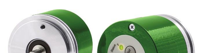
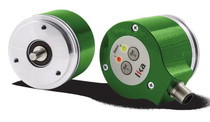
32 ROTACOD Output circuits and fieldbus interfaces The absolute position information can be provided to the following control via a wide variety of output circuits (interfaces). Typically, we can distinguish between electrical interfaces (parallel, serial, analogue) and fieldbus interfaces. The absolute encoders are customarily fitted with either parallel or serial (SSI, BISS, etc.) output circuits, the analogue circuit is more rarely used. The electrical interfaces are simple, cost-effective and easily fulfil the requirements of most industrial applications. Nevertheless in the last years fieldbus interfaces are rapidly gaining ground worldwide because of their compatibility in more complex installations. Fieldbus technology in fact permits to improve performances thanks to complete device interface (bi-directional data transmission, enhanced programmability, diagnostic information, etc.), achieve communication transparency, simplify and standardize installations allowing several devices to be simply connected in the same network. In addition the use of standardised bus cables provides a simplified and safe connectivity thus saving time and money whilst reducing the risk of errors. Probably, the parallel output is, among the electrical interfaces, the most commonly used for the absolute encoders and most and foremost for the single-turn encoders, as an alternative to serial or SSI electrical interfaces. It is very simple and fast and provides the output information (such as the absolute position) simultaneously (this means that multiple bits are output in the same time using separate transmission lines for each one), in pure Binary, Gray or BCD code format. Parallel output encoders integrate NPN, PNP or Push-Pull drivers (for any information see page 22). Zero setting/preset, Counting direction, Latch, Tri-state and Parity bit features are often implemented (see page 40). Because of the increasing resolutions of the absolute encoders this output circuit requires up to 32 wires per cable and consequently additional components, so having a negative impact on the costs; for this reason the parallel output is more and more decreasing in the preference nowadays and often replaced by serial or fieldbus interfaces. The following table shows the maximum cable lengths in relation to frequencies. Parallel output Max. cable length m 100 [328] 50 [164] 30 [100] Frequency [khz] At ambient temperature (23 C), V enc = 24V Advantages: fast, all data available simultaneously. Disadvantages: more lines mean more conductors and components and therefore higher number of inputs, short cable lengths. For recommended NPN, PNP and Push-Pull input circuits please refer to page
33 ROTACOD Output circuits and fieldbus interfaces Analogue electronics are especially used for position or velocity feedback and provide a continuously variable unique signal, namely a voltage or current signal, instead of a two-level discrete representation of the information (digital signal). Their choice and use depends on the specific application, 4-20mA current output is nearly the standard in several fields and further allows for a refined OVERRUN function. In the optical encoders, the digital information is converted into current or voltage analogue signals before being issued to the following electronics. A full range of both voltage and current analogue signal outputs are available: 0 to 5V, 0 to 10V, -5 to +5V, -10 to +10V, 4 to 20mA, 0 to 24mA and 4 to 24mA. Encoders with analogue output interface are available in both single-turn and multi-turn version. Among the models available in the analogue encoders portfolio, EM58 PA is the fully programmable absolute analogue encoder with software-selectable analogue outputs. It allows the full range of voltage and current outputs to be programmed according to any specific requirement. The analogue output encoders range includes special versions equipped with keys fitted in the rear of the enclosure; they allow to simply define the linear or angular displacement of the application by setting the start and stop reference points of the measuring range. Thus the initial and final limits of the stroke are the minimum and maximum values of the analogue range respectively. It doesn t matter whether the displacement to measure is 1-, 25- or 99.5-revolution long, it will be scaled in the whole analogue range. The analogue encoders can further implement the OVERRUN function. It operates as a limit switch and allows to detect an overtravel position either by decreasing/increasing the output value beyond the analogue range or by keeping low/high the signal level outside the set axis travel. Analogue output The following table shows the maximum cable lengths for both voltage and current analogue outputs. Max. cable length m Voltage analogue Current analogue At ambient temperature (23 C), V enc = 20V 100 [328] with 1 MΩ max. load 150 [490] Advantages: current signals are better suited to transmission over long cable runs, voltage electronics interface directly with D/A and A/D converters and analogue multiplexing devices. Disadvantages: more susceptible to noise than digital circuits, affected by EMI Recommended input circuits +Vdd +V +V DC/DC Encoder circuit DAC Vout ADC Voltage INPUT 0V 0V +Vdd +V +V DC/DC Encoder circuit DAC Iout RL ADC Current INPUT 0V 0V 33
34 ROTACOD Output circuits and fieldbus interfaces SSI (the acronym for Synchronous Serial Interface) is a synchronous point-to-point serial interface engineered for unidirectional data transmission between one Master and one Slave. Developed in the first eighties, it is based on the RS-422 serial standard. Its most peculiar feature is that data transmission is achieved by synchronizing both the Master and the Slave devices to a common clock signal generated by the controller; in this way the output information is clocked out at each controller s request. Furthermore only two pairs of twisted wires are used for data and clock signals, thus a six-wire cable is required. The main advantages in comparison with parallel or asynchronous data transmissions are: less conductors are required for transmission; less electronic components; possibility of insulting the circuits galvanically by means of optocouplers; high data transmission frequency; hardware interface independent from the resolution of the absolute encoder. Furthermore the differential transmission increases the noise immunity and decreases the noise emissions. It allows multiplexing from several encoders, thus process controls are more reliable with simplified line design and easier data management. Data transmission is carried out as follows. At the first falling edge of the clock signal (1, the logic level changes from high to low) the absolute position value is stored while at the following rising edge (2) the transmission of data information begins starting from the MSB. At each change of the clock signal and at each subsequent rising edge (2) one bit is clocked out at a time, up to LSB, so completing the data word transmission. The cycle ends at the last rising edge of the clock signal (3). This means that up to n + 1 rising edges of the clock signals are required for each data word transmission (where n is the bit resolution); for instance, a 13-bit encoder needs 14 clock edges. If the number of clocks is greater than the number of bits of the data word, then the system will send a zero (low logic level signal) at each additional clock, zeros will either lead (LSB ALIGNED protocol) or follow (MSB ALIGNED protocol) or lead and/or follow the data word (TREE FORMAT protocol). After the period Tm monoflop time, having a typical duration of 12 µsec, calculated from the end of the clock signal transmission, the encoder is then ready for the next transmission and therefore the data signal is switched high. SSI interface has a frequency of data transmission ranging between 100 khz and 2 MHz. The clock frequency (baud rate) depends on the length of the cable and must comply with the technical information reported in the following table: Max. cable length m 400 [1310] 200 [655] 100 [330] 60 [200] 30 [100] 15 [50] Clock frequency [khz] At ambient temperature (23 C) The clock signal has a typical logic level of 5V, the same as the output signal which has customarily a logic level of 5V in compliance with RS-422 standard. If the single-turn resolution is lower than 13 bits, then the protocol will provide 13 clock signals (+1 edge, as stated); if the single-turn resolution is higher than 13 bits, then the protocol will provide 25 clock signals instead. Multi-turn encoders provide either 25 or 32 clock signals according to the length of the data word (bit resolution). The output code can be either Binary or Gray. 34
.")
. Thus the multi-turn information is transmitted first.")
35 ROTACOD Output circuits and fieldbus interfaces Tree format is the most common protocol and the SSI standard. It is typically used in the single-turn encoders having a resolution up to 13 bits and in the multi-turn encoders having a resolution up to 25 bits (13-bit single-turn + 12-bit multiturn). The whole transmitted data is divided into 12 bits on the left side of the central axes dedicated to the information on the number of revolutions; and into 13 bits on the right side of the axes dedicated to the information on the number of counts per revolution (see Figure 2). Thus the multi-turn information is transmitted first. If less than bits are required, then unused bits are forced to logic level low (0); they lead the multi-turn information on one hand and follow the single-turn information on the other hand. As you can easily assume, the Tree format protocol is not compatible with single-turn encoders having a resolution higher than 13 bits and with multi-turn encoders having an overall resolution higher than 25 bits and a single-turn information higher than 13 bits anyway. In single-turn encoders the protocol will provide 13 clock signals; while in multiturn encoders the protocol will provide 25 clock signals. TREE FORMAT protocol (standard) 1-13 bit single-turn protocol scheme 2-25 bit multi-turn protocol scheme 35


36 ROTACOD Output circuits and fieldbus interfaces LSB right aligned protocol is used as an alternative to the Tree format protocol and allows to right align the bits, beginning from MSB to LSB; LSB is then sent at the last clock cycle. If the number of clock signals is higher than the data bits, then unused bits are forced to logic level low (0) and lead the data word. This protocol can be used in encoders having any resolution. Information can be variously arranged for single and multi-turn versions. If the encoder overall resolution is lower than 13 bits, then the protocol will provide 13 clock signals; if it is between 13 and 25 bits, then the protocol will provide 25 clock signals; if it is higher than 25 bits, then the protocol will provide 32 clock signals instead. LSB RIGHT ALIGNED protocol 3 Up to 13 bit single turn LSB RIGHT ALIGNED protocol scheme 4 Up to 25 bit single turn and multi turn LSB RIGHT ALIGNED protocol scheme 5 From 26 bit multi turn LSB RIGHT ALIGNED protocol scheme 36
 and follow the data word.")
37 ROTACOD Output circuits and fieldbus interfaces MSB left aligned protocol is a further alternative and allows to left align the bits, beginning from MSB to LSB; MSB is then sent at the first clock cycle. If the number of clock signals is higher than the data bits, then unused bits are forced to logic level low (0) and follow the data word. Also this protocol can be used in encoders having any resolution. Information can be variously arranged for single and multi-turn versions. The number of clocks to be sent to the encoder must equal the number of data bits at least, anyway it can be higher, as stated previously. The great advantage of this protocol over the TREE format and the LSB RIGHT ALIGNED format is that data can be transmitted with a minimum time loss and the Tm monoflop time can immediately follow the data bits without any additional clock signal. MSB LEFT ALIGNED protocol 6 MSB LEFT ALIGNED protocol scheme Advantages: simple, efficient and cost-effective, less conductors, less electronic components, transmission rate up to 2 Mbps, circuit can be galvanically insulated by means of optocouplers, increased noise immunity, long cable runs. Disadvantages: point-to-point architecture, transmission speed lower than parallel interface. Recommended input circuit ENCODER SSI/BISS VDriver MASTER DATA_ENC DATA+ VCC DATA VDriver_enc VDriver CLOCK CLOCK_ENC CLOCK+ DATA- CLOCK- 37
38 ROTACOD Output circuits and fieldbus interfaces BiSS is a digital, bidirectional, serial and synchronous interface expressly developed and released in 2002 for sensors and actuators. Nowadays it has become widely popular in several industrial sectors that require high operating speeds and improved robustness against EMC interference, while simultaneously reducing costs. It is hardware compatible with SSI interface but offers additional features and options such as multi-slave networking (up to 8 Slaves), higher frequency of data transmission up to 10 MHz, diagnostic information. BiSS safeguards communication between position encoders or measuring devices and industrial controls, such as a drive control and is able to transfer measurement values coming from up to 8 Slaves simultaneously, if necessary. Lika Electronic implements both B-mode and C-mode versions of the BiSS protocol. For 1 to 8 subscribers (Slaves) the Master interface provides a clock signal both for the simultaneous acquirement of all position information and the following synchronous serial data transmission. Only four unidirectional RS-422 data lines are required; minimum Slave electronics are incorporated into ICs (integrated circuits). When the Master sends a clock pulse on the line MA, then the Slave sends the reply directly on the return line SL with the stored position data. Commands and parameters can be swapped on a PWM pulse form; this is, however, not necessary to start the BiSS protocol. Within each data cycle the Master learns and compensates for line delays, thus permitting clock rates up to 10 Mbit/s even using cables up to 1000-m long. Changes which may occur in line conditions, for example during cable drag, are corrected. The precision of the synchronization among several position encoders and along various axes is less than 1 microsecond; furthermore the signal delay registered by the Master is clearly accessible to the control unit, thus allowing further optimization. The BiSS protocol classifies each subscriber under one of the following data sections: sensor data, actuator data, register data and multi-cycle data. These data sections can boast various configurations in order to customize and optimize access and transmission performances and in this way they fulfil the requirements of a large variety of sensor applications. A bidirectional parameter communication for device configuration - available also for parameters referred to as OEM - is customarily available in the register data section. Data that changes slowly, such as counts per revolution or motor temperatures, is allocated to the multi-cycle data section; while data that changes quickly is allocated to the sensor data section. Control cycle times shorter than 10 µs are thus not a problem, even for data words up to 64-bit long. In fact there is enough space in the protocol for redundancy and this space is customarily used to implement a CRC (cyclic redundancy check). Framed by just one start and one stop bit, sensor data is transmitted at the highest core data rate; a single multicycle data bit is optional. The individual user s freedom of design for specific devices is not curbed by the necessity of keeping solutions compatible with other BiSS products and this results in cutting down on unnecessary additional costs. A BiSS subscriber is defined in its entirety by just a few parameters; an ML device description file supplied with the sensor makes it easier and faster to set up the unit with a control system. If this does not have a BiSS input yet, BiSS devices can be switched over to SSI mode. Any further information on BiSS interface is available at Advantages: simple, efficient and cost-effective, full digital, bi-directional and synchronous, less conductors, less electronic components, higher frequency of data transmission up to 10 MHz, long cable runs. Disadvantages: transmission speed lower than parallel interface. Max. cable length m [ft] 1000 [3280] 500 [1640] 200 [655] 100 [330] 60 [200] 25 [80] 10 [35] Frequency 100 khz 200 khz 500 khz 1 MHz 2 MHz 5 MHz 10 MHz At ambient temperature (23 C) 38
.")
39 ROTACOD Output circuits and fieldbus interfaces Lika absolute encoders are always Slave devices and comply with the BiSS C-mode interface and the Standard encoder profile. They support a point-to-point configuration, thus they have to be installed in single-master - single-slave networks only (not in single-master - multi-slave networks). CLOCK and DATA signal levels are according to EIA standard RS-422. The BiSS C-mode protocol implemented in Lika absolute encoders uses two types of data transmission protocols: Single Cycle Data (SCD): is the primary data transmission protocol. It is used to send process data from Slave to Master. Control Data (CD): transmission of a single bit following the SCD data. It is used to read or write data into the registers of the slave. Among the parameters available: position readout, speed value, scaling function, preset and offset values. BiSS at a glance Number of stations Setting the nodes Setting the baud rate Transmission rate Cable length Cable Up to 10Mbit/s Up to 1000 m Lika T12 type cable Recommended input circuit ENCODER SSI/BISS VDriver MASTER DATA_ENC DATA+ VCC DATA VDriver_enc VDriver CLOCK CLOCK_ENC CLOCK+ DATA- CLOCK- 39
40 ROTACOD Input & output functions for SSI and Bit parallel encoders Using the Zero setting / Preset function, the output value can be set either to zero (reset) or to a desired value (preset) via an external signal issued by a PLC or other controller device. When the internal microprocessor receives the signal it resets or presets the output information. This can be very useful, for example, for synchronizing the encoder readout with the 0 mechanical position of the axis to measure. To set the zero or the preset, the Zero setting / Preset signal must be connected to +Vdc for 100 µs at least; then it must be disconnected. In normal conditions its voltage must be at 0Vdc or floating. The Zero setting / Preset operation must be performed after having set the Counting direction (Complementary). We suggest setting the zero / Preset when the encoder is in stop. It is also known as Complementary. The counting direction circuit allows the count up also when the shaft is rotating counterclockwise. Connect the counting direction input to 0VDC to have an increasing count when the encoder is turning clockwise (CW, viewed from the shaft side); connect the counting direction input to +VDC to have an increasing count when the encoder is turning counterclockwise (CCW). This feature is available as a standard in the whole range of absolute encoders. Parity bit is an optional function used for checking in a very basic way whether errors occur during transmission. It is the simplest form of error detecting code and offers the advantage that only one bit is required for error detection. On the other hand it only indicates that a parity error occurred in the transmission and there is no way to determine which particular bit is corrupted. Furthermore the parity bit is only guaranteed to detect an odd number of bit errors. If an even number of bits have errors, the parity bit records the correct number of ones, even though the data is corrupt. It can be either even or odd. When even parity bit is set, the sum of the bits having logic level 1 in the character has to be even. The reverse when odd parity bit is set. Lika encoders provide an ODD parity bit. Latch circuit allows to temporarily store the information that the encoder is providing to output in a defined moment. Information will be available until the latch signal is deactivated. This can be very useful when, for instance, the transmission speed of the encoder is faster than the data acquisition of the interface electronics: in this case information is frozen until data is fully acquired. Connect the Latch input to 0Vdc to deactivate this function; on the contrary, connect it to +Vdc to activate the Latch and frozen the output information. Tri-state circuit allows the transmission of the output information from the encoder to be interrupted. In this way, for instance, it is possible to have several encoders connected in parallel (multiplexing) but a single control unit and shared circuitry; information about the position of each encoder can be acquired with an updating time equal to the duration of the multiplexing cycle. Connect the Tri-state input to +Vdc to run the encoder is a standard mode (outputs are normally activated); connect it to 0Vdc or floating voltage to enable the function and thus disable the outputs. Zero setting / Preset Counting direction Parity bit Latch Tri-state At-a-glance summary Function 1 (high) 10 Vdc 0 (low) 8 Vdc Zero setting Activated Deactivated Counting direction CCW positive counting CW positive counting Latch Data stored Latch deactivated Tri-state Outputs activated Outputs deactivated Recommended input circuit +V +V +V +V +V 1K 1K 1K 1K ENCODER CIRCUIT 2K2 2K2 2K2 2K2 100nF 100nF 100nF 100nF 22K 22K 22K 22K Zero setting Counting direction Latch Tristate 40
41 ROTACOD Cable length We highly recommend the cable lengths reported in the following tables to be respected strictly. Tests have been carried out by connecting the encoder to the Lika LD200 universal position display through a DS3486 line receiver complying with EIA standards. Data listed below may vary due to the following factors: the electrical noise coming from the power supply line; the electrical noise coming from the earthing (ground) connection of the encoder; the features of the controller connected to the encoder; the ambient temperature; the working voltage of the encoder (parallel output only). Cable length Maximum cable lengths in relation to counting frequency Interface / output circuit Parallel output (20V) SSI (RS-422) BiSS Max. cable length m Frequency [khz] 100 [328] [164] [1310] [245] [3280] [200] 2000 Max. cable length m [ft] Analogue output Voltage analogue 100 [328] with 1 MΩ max. load Current analogue 150 [490] At ambient temperature (23 C) Please note the higher the resolution and the maximum rotational speed of the encoder, the higher the counting frequency. There is a straight relationship between the counting frequency and the signal distortion. The longer is the cable in fact, the greater is its capacitance; and capacitance affects the signal quality causing the higher frequencies to be filtered so distorting the signal. Using the following formula you can easily calculate the number of revolutions the encoder is allowed to reach starting from the counting frequency value. RPM = Max.frequency(kHz)*60*1000 PPR where RPM is revolutions per minute and PPR is pulses per revolution. This formula can be very useful -for instance- when you know the maximum frequency that can be transmitted over a given cable length and you need to know the maximum rotation speed the encoder is allowed to reach at the required resolution. 41
42 ROTACOD Output circuits and fieldbus interfaces EtherCAt (Ethernet for Control Automation Technology) is an open Ethernet-based fieldbus system which applies Ethernet features to fieldbus technology. Its development and administrative management are entrusted to the EtherCAT Technology Group (ETG) ( EtherCAT bus is simply a single large Ethernet device which receives and sends Ethernet telegrams (standard Ethernet dataframes in accordance with IEEE 802.3). However, the device does not contain an Ethernet controller, but one Master and some Slaves. Moreover any control with a commercially available Ethernet controller should be able to be used as an EtherCAT Master: standard structural components in fact such as Ethernet switches should be usable for EtherCAT. Telegrams are processed directly on the fly. While the telegrams (delayed by only a few bits) are already passed on, the Slave recognizes relevant commands and executes them accordingly. Processing is done within the hardware and is therefore independent of the response times of any microprocessors that may be connected. Flexible topology variants arbitrarily extendable namely Line, Star, Tree, Daisy Chain + Drop Lines are possible, even in the same network. Slave configuration can be done both via ML configuration file (EtherCAT Slave Information ESI) provided by the device manufacturer and by loading data directly from EEPROM (Slave Information Interface SII). The number of devices which can be installed in the EtherCAT network is virtually unlimited, while up to nodes can be connected for each segment. The transmission rate is 100 Mbit/s with full-duplex communication (Fast Ethernet). Lika encoders with EtherCAT interface are Slave devices and support the CANopen Over EtherCAT (CoE) protocol for data transfer; in particular they comply with Device Profile for encoders Class 2 established in CIA Draft Standard 301 and CIA Draft Standard 406 publications for CANopen; furthermore they comply with EtherCAT standard established in ETG.1000 protocol conformance. As CANopen communication protocol, also EtherCAT uses PDOs and SDOs. PDO (Process Data Object) messages are used to process real time data (transmission of process data in real time, bus cycle time of 62 µs only, the faster in the market); while SDO (Service Data Object) messages are used to set and read values from the Object dictionary of the remote device. The following transmission modes are available: FreeRun: asynchronous mode, encoder position is sampled directly from EtherCAT frame sent by the Master; position update is performed by an internal timer of the controller every 100 microseconds; Synchronous with SM3: data is sampled and then copied into Sync Manager buffer as soon as the previous data are read by the Master (SM event); in this way new sampled data is synchronous with Master readings; Synchronous with DC: data is sampled and then copied into Sync Manager buffer simultaneously at SYNC0 event generated by the ESC capture/compare unit. Furthermore, Lika devices support the EtherCAT State Machine ESM with Init state, Pre-operational state, Safe-Operational state and Operational state; and implement the FOE protocol for firmware update. Among the parameters available: position readout, counting direction, scaling function, preset and offset values, errors register and diagnostic information. Encoders are fitted with diagnostic LEDs; they do not need bus termination resistance. EtherCAT at a glance: Number of stations Virtually unlimited Setting the nodes Software, automatic Setting the baud rate - Transmission rate 100 Mbit/s full duplex Cable length Up to 100 m (330 ft) Cable Standard EtherCAT / M12 connectors 42
43 ROTACOD Output circuits and fieldbus interfaces PROFINET IO is the open industrial network devised for automation applications and built on the Ethernet application layer (TCP/IP and IT standards). For PROFINET IO the layers 1 through 7a of the ISO/OSI (Open Systems Interconnection) reference model are exclusively based on internationally proven standards. The functionality of PROFINET is defined in layer 7b. PROFINET IO complies with IEEE802.3 Ethernet Standard and follows the standards IEC and IEC61784, so it is 100% Ethernet compatible. Its technology development and standardization are entrusted to Profibus & Profinet International (PI), the international umbrella organization including members of more than 1400 companies ( PROFINET IO is expressly developed to connect controllers (named IO controllers, equivalent to Profibus DP Masters), peripheral devices (named IO devices, similar to Profibus DP Slaves) and programming devices / PCs (named IO supervisors) with Ethernet Real Time (RT) and Isochronous Real Time (IRT) communication all the way. Real Time channel is used for time-critical process data and allows to meet the real-time requirements of the automation engineering (cycle times < 500 µs, jitter < 1 µs); while IRT is suitable for sophisticated motion control and high performance applications in factory automation and permits cycle times lower than 250 µs with less than 1 µs jitter. The standard TCP/IP channel is used for parametrization, configuration and acyclic read/write operations. A PROFINET IO system requires at least one IO Controller and one IO Device. The most frequent network topologies can be implemented and even mixed together including Star, Line, Tree and Ring structures by means of copper or fiber-optic cables. The number of devices (each one fitted with its own MAC address, IP address and device name) which can be connected in the PROFINET network is virtually unlimited. The transmission rate is 100Mbit/s with full duplex communication (Fast Ethernet). PROFINET IO Devices are configured using a configuration tool which acts as the IO Supervisor. The IO Supervisor uses a GSD (General Station Description) file based on ML language, thus it is called GSDML file. PROFINET encoders from Lika Electronic fully comply with the encoder profile specifications V4.1 version Please note that the encoder profile is based on the PROFIdrive profile. Furthermore they fulfil the requirements of the Application Classes 3 and 4, thus they are intended for clock-synchronous (isochronous) real-time applications with cyclic and synchronous data transmission. Furthermore they can also be used in applications without clock synchronization. PROFINET encoders supports the standard telegrams 81, 82, 83 and 84. The IO data is transferred to and from the Encoder Object (EO) via the Cyclic Data Exchange Service. The EO comprises the following mandatory functionalities: parameters; measuring task (i.e. position value, velocity value, ); IO data (cyclical transmission of control and actual values); support for Alarm Mechanism. Among the parameters available: code sequence, scaling function, preset (Class 4 functionalities), position readout, offset value, velocity value, velocity measuring unit, acyclic Error Data communication and diagnostic information. Encoders are fitted with diagnostic LEDs. PROFINET at a glance Number of stations Setting the IP address Setting the baud rate Transmission rate Cable length Cable Virtually unlimited Software / automatic via DCP Mbit/s full duplex Up to 100 m 330 ft M12 D-coded Profinet connectors 43

44 ROTACOD Output circuits and fieldbus interfaces Modbus RTU is a serial communication open protocol developed in the seventies of the last century by Modicon which is now widely used in the industry and has become a standard for device-to-device communication in several industrial automation systems. The development and update of Modbus protocol is managed by the Modbus Organization ( formed of independent users and suppliers of Modbus compliant devices. Modbus RTU allows for communication between up to 247 nodes in a true multi-drop network over a serial EIA-485 physical layer. The Modbus Serial Line protocol is a Master Slaves protocol. Lika encoders are Slave devices and implement the Modbus application protocol (level 7 of OSI model) and the Modbus over Serial Line protocol (levels 1 & 2 of OSI model). Only one Master is connected to the bus and one or several Slave nodes can also be connected to the same serial bus. A Modbus communication is always initiated by the Master. The Slave nodes will never transmit data without receiving a request from the Master node. MODBUS RTU messages (registers) are simple data strings with 16-bit CRC (Cyclic Redundant Checksum for error checking). The simplicity of these messages is meant to ensure reliability. Modbus interface does not need any configuration file to be installed. The main reasons behind such large implementation and diffusion of the Modbus interface are: Modbus bases on RS-485/RS-232 serial communication which is well established and universally supported; it is basic yet complete, flexible and most of all reliable; it is really simple to implement and easy-to-use; it is significantly more inexpensive to deploy than other industrial fieldbus protocols and requires less resources; it is open and can be used royalty-free. Encoders fitted with Modbus RTU interface come with a program expressly developed and released by Lika Electronic: it allows the operator to set the working parameters of the device; control manually some movements and functions; and monitor the work cycles of the unit. The program is supplied for free and can be installed in any PC fitted with a Windows operating system (Windows P or later). In this way you can easily and quickly programme, set up and start the encoder even before mounting at your convenience. Among the parameters available: position readout, counting direction, scaling function, preset and offset values, errors register and diagnostic information. Encoders are fitted with diagnostic LEDs and bus termination resistance. Modbus at a glance Number of stations Setting the nodes Setting the baud rate Transmission rate Cable length Cable Up to 247 Dip switches Dip switches Up to Kbit/s Up to 1000 m 3300 ft Cable / M12 connectors 44
 (www.profibus.com).")
 reference model and developed on the four Physical (1), Data Link (2), Application (7) and User")
45 ROTACOD Output circuits and fieldbus interfaces Profibus (a portmanteau word of PROcess Field BUS) is a standard digital communication system for fieldbus widely used in automation industry for exchanging control data and I/O signals. Its technology development and administrative management are entrusted to the Profibus International organization (PI) ( Profibus complies with the European Fieldbus Standard EN which allows a standardized development. It is the most popular fieldbus protocol in Europe. Profibus communication protocol is built in accordance with the ISO/OSI (Open Systems Interconnection) reference model and developed on the four Physical (1), Data Link (2), Application (7) and User layers. A Profibus network supports up to 126 stations and transmission rates up to 12Mbit/s. Serial communication is always used. Profibus is a Multi-Master Multi-Slave system with cyclic or acyclic access. Master device is able to detect all the Slaves connected to the network thanks to the GSD (General Station Description) configuration files which are provided by the device manufacturers (or GSE, GSI, etc. depending on the language being used). GSD file is a readable ASCII text file and contains both general and device-specific information needful for communication. Furthermore each of the entries describes a feature that is supported by the Profibus device. Profibus protocol supports a Master-Slave access method where the Master controls the communication on the bus and is the only allowed to issue messages without external request; while the Slave is a passive peripheral device and is only enabled to reply to explicit requests from the Master. In conjunction with Master-Slave access method, token passing procedure is implemented allowing the Master devices to take control of the bus alternately. This procedure is intended to ensure that each Master keeps the token ownership for equal and regular time slices. Time slice assigned to each Master for managing the network depends on the number of active nodes in the bus and the token hold time. In this way token is passed periodically from node to node around the network in a defined, recurring sequence (logical ring). 45
46 ROTACOD Output circuits and fieldbus interfaces RS-485 is the most commonly used transmission technology for PROFIBUS; it is simple, easy-to-use and cost-effective and is primarily used for tasks that require high transmission rates. RS-485 transmission technology uses shielded twisted pair copper cables with one conductor pair. A Profibus system that is to accommodate more than 32 stations must be divided into several bus segments. These individual bus segments with up to 32 stations each one are connected to each other by repeaters (also referred to as line amplifiers). The following table shows the maximum transmission rates in relation to permissible line length. Baud rate [Kbit/s] 9,6 19,2 93,75 187, Max. cable length 1200 m 4000 ft 1200 m 4000 ft 1200 m 4000 ft 1000 m 3300 ft 400 m 1300 ft 200 m 660 ft 100 m 330 ft Lika encoders with Profibus interface (absolute single-turn and multi-turn encoders) implement Profibus DP (Decentralized Peripherals) communication protocol and can be set as Class 1, Class 2 or Class 2 (+VEL) devices. Encoder class has to be set at device configuration. Class 1 provides the basic functionalities of DP such as: position readout; setting of the counting direction; setting of the preset value; 16-byte reduced diagnostic information (Hx58x series only). Class 2 supports extended enhancements in addition to functionalities of Class 1: scaling function; 63-byte extended diagnostic information (Hx58x series only). Class 2(+VEL) contains further enhancements in addition to functionalities of Class 2: transmission of velocity value (Hx58x series only); unit of measurement for velocity value (Hx58x series only). Thanks to Profibus DP, encoders can be coupled reducing costs and increasing performances; furthermore they fulfil each configuration, parametrization and diagnostic requirement. Among the parameters available: position readout, counting direction, velocity value (Hx58x series only), scaling function, preset value. Encoders are fitted with diagnostic LEDs and bus termination resistance. Profibus at a glance Number of stations Setting the nodes Setting the baud rate Transmission rate Cable length Cable Up to 126 Dip switches or software Software Up to 12Mbit/s Up to 1200 m 4000 ft Standard Profibus M12 connectors 46


47 ROTACOD Output circuits and fieldbus interfaces First developed in the automotive industrial sector, CANbus (Controller Area Network) serial bus system has thereafter established itself in a variety of industrial applications, in particular where noisy electrical environment conditions could lead to unsafe communication. International Organization for Standardization (ISO) has established the CAN standard in ISO 11898, developing the protocol over the first two layers of the ISO/OSI (Open Systems Interconnection) reference model; while all the other protocol layers are the network designer s choice. Unlike other protocols that define all ISO/OSI layers, developers intentionally limited the CAN specifications so manufacturers are free to choose a specific implementation of the higher protocol layers; for this reason other CAN-based protocols have been developed at higher layers as CANopen and DeviceNet or other proprietary protocols. CANbus standard and CANopen communication protocol are administered by CAN in Automation ( while DeviceNet communication protocol is managed by the Open DeviceNet Vendors Association ( CANopen is widely used in Europe, while DeviceNet is more popular in North America. CANopen is a CAN-based communication protocol which implements the higher layers of the ISO/OSI (Open Systems Interconnection) reference model. Its technology development and standardization are entrusted to CiA (CAN in Automation). CANopen is a Single Master - Multi Slave communication protocol. Master device is able to detect all the Slaves connected to the network thanks to the EDS (Electronic Datasheet) configuration files which are provided by the device manufacturers (EDS files for CANopen devices are different from EDS files for DeviceNet devices). The EDS file contains the complete list of all working parameters of the Slave device and information for configuring the communication between the Master and the Slave. In the CANopen network, the Master device must be addressed to 0, while the Slave nodes have address between 1 and 127. Maximum transmission rate is up to 1Mbit/s. The following table shows the maximum transmission rates in relation to permissible line length. Baud rate [Kbit/s] Max. cable length , m ft 2500 m 8200 ft 1000 m 3300 ft 500 m 1650 ft 250 m 820 ft 100 m 330 ft 50 m 165 ft 30 m 100 ft Lika encoders with CANopen interface (absolute single-turn and multi-turn encoders) comply with Device Profile for encoders Class 2 established in CIA Draft Standard 301 and CIA Draft Standard 406 publications; in specific applications they comply with CIA Draft Standard Proposal Application Profile for Lift Control Systems. 47
48 ROTACOD Output circuits and fieldbus interfaces Lika devices with CANopen support the CANopen network management (NMT) slave state machine (Initialization state, Pre-operational state, Operational state, Stopped state) and use COBs (Communication Objects), in particular: NMT (Network Management) messages to issue state machine change commands (i.e. to start and stop the devices) and detect remote device boot-ups and error conditions; PDO (Process Data Object) messages to process real time data (transmission of process data in real time); and SDO (Service Data Object) messages to set and read values from the Object dictionary of the remote device. Furthermore they implement some standard objects such as the synchronization object (SYNC) and the Nodeguarding. Among the parameters available: position readout, counting direction, velocity value (Hx58x series only), scaling function, preset and offset values, two min. and max. software limit switches, errors register and diagnostic information. Encoders are fitted with diagnostic LEDs and bus termination resistance. CANopen at a glance Number of stations Setting the nodes Setting the baud rate Transmission rate Cable length Cable Up to 127 Dip switches or software Dip switches or software Up to 1Mbit/s Up to 5000 m ft Standard CANopen / M12 connectors DeviceNet is a CAN-based communication protocol which implements the higher layers of the ISO/OSI (Open Systems Interconnection) reference model. Designed by Allen-Bradley (now owned Rockwell Automation) and developed and managed by ODVA (Open DeviceNet Vendor Association), DeviceNet is a peer-to-peer data exchange protocol where the Master/Slave communication is set as a sub-function of the peer-topeer communication. The Master device is able to detect all the Slaves connected to the network thanks to the EDS (Electronic Datasheet) configuration files which are provided by the device manufacturers (EDS files for DeviceNet devices are different from EDS files for CANopen devices). The EDS file contains the complete list of all working parameters of the Slave device and information for configuring the communication between the Master and the Slave. DeviceNet network supports up to 64 stations (from 0 to 63) and transmission rates up to 500Kbit/s. The following table shows the maximum transmission rates in relation to permissible line length. Baud rate [Kbit/s] Max. cable length 500 m / 1650 ft 250 m / 820 ft 100 m / 330 ft Lika encoders with DeviceNet interface (absolute single-turn and multi-turn encoders) are Group 2 only server devices and do not support UCMM (Unconnected Message Manager) functionality. Lika DeviceNet encoders support two kind of communication messages: I/O messages: they are high-priority messages whose meaning is explained in the Message-ID ; Slave devices use these messages to send process data (position and velocity values); Explicit Messages: they are low-priority messages and are used to start and close communications between the Master and the Slave, to read and write Slave configurations and to send diagnostic messages. The following transmission modes are available: polled where the Master device sends a polled request and the Slave device replies sending its position value; cyclic, where the Slave sends an I/O message cyclically, time between two transmissions is set in the Expected packet rate of cyclic mode; change of state, where the Slave sends an I/O message every time its state changes or every heartbeat rate. Among the parameters available: position readout, counting direction, scaling function, preset and offset values, error messages and diagnostic information. Encoders are fitted with diagnostic LEDs and bus termination resistance. DeviceNet at a glance Number of stations Setting the nodes Setting the baud rate Transmission rate Cable length Cable Up to 64 Dip switches Dip switches Up to 500Kbit/s Up to 500 m 1650 ft Standard DeviceNet M12 connectors 48
 Power supply (Vdc) NPN PNP 1Vpp Push-Pull Line Driver Universal circuit Operating temp. C ( F) min. - max. Protection max.")
 IP67 Light-duty Food I40 - I41 Optical encoders, compact 70")
 -25 +85 (-13 +185) IP65 CB50 Optical encoder for servo motors UVW")
49 ROTAPULS incremental encoders Page Housing ø (mm) Shaft max. ø (mm) Shaft rotational speed max. (rpm) connector cable Connection Resolution max. (PPR) Output frequency max. (khz) Power supply (Vdc) NPN PNP 1Vpp Push-Pull Line Driver Universal circuit Operating temp. C ( F) min. - max. Protection max. I28 Optical miniature encoder ( ) IP54 Light-duty MI36 - MC36 Magnetic encoders, compact ( ) IP67 Light-duty MI36K - MC36K Magnetic encoders Stainless steel version Food industry ( ) IP67 Light-duty Food I40 - I41 Optical encoders, compact ( ) IP66 Light-duty CK41 - CK46 Optical encoders, compact ( ) IP65 Light-duty C50 - C51 Optical encoders High temperature Industrial / Feedback ( ) ( ) IP65 CB50 Optical encoder for servo motors UVW signals / 8 poles ( ) IP20 Feedback I58 - I58S Optical standard encoders ( ) IP65 Industrial I58SK Optical encoder Stainless steel version Food industry Industrial Food ( ) IP66 49
 Power supply (Vdc) NPN PNP 1 Vpp Push-Pull Line Driver Universal circuit Operating temp. C ( F) min. - max. Protection max.")
 IP65 Industrial C58A - C58R Optical standard encoders Through hollow shaft 88 58 15 6000 5000 100 +5 +10 +30 +5 +30-40 +100 (-40 +212) IP65 Industrial / Feedback CK58 -")
50 ROTAPULS incremental encoders Page Housing ø (mm) Shaft max. ø (mm) Shaft rotational speed max. (rpm) connector cable Connection Resolution max. (PPR) Output frequency max. (khz) Power supply (Vdc) NPN PNP 1 Vpp Push-Pull Line Driver Universal circuit Operating temp. C ( F) min. - max. Protection max. IP58 - CP58 Programmable encoder ( ) IP65 Industrial C58 - C59 - C60 Optical standard encoders Through hollow shaft ( ) IP65 Industrial C58A - C58R Optical standard encoders Through hollow shaft ( ) IP65 Industrial / Feedback CK58 - CK59 - CK60 Optical standard encoders Blind hollow shaft ( ) IP65 Industrial CB59 - CB60 Optical encoders for servo motors Sine/cosine : / 1 sin/cos ( ) IP40 Feedback / Lift MI58 - MI58S Magnetic encoders Sealed circuits ( ) IP67 Industrial MC58 - MC59 - MC60 Magnetic encoders Sealed circuits Through hollow shaft ( ) IP67 Industrial I65 - IT65 Optical encoders Square flange, US size ( ) IP66 Industrial IT68 Optical encoder ( ) IP66 Industrial 50
 Shaft rotational speed max.")
 Power supply (Vdc) NPN PNP 1Vpp Push-Pull Line Driver Universal circuit")

 IP65")
 IP65 C82 Optical encoder")
 110 112 115")
")

 IP65 Heavy-duty")
51 ROTAPULS incremental encoders Page Housing ø (mm) Shaft max. ø (mm) Shaft rotational speed max. (rpm) connector cable Connection Resolution max. (PPR) Output frequency max. (khz) Power supply (Vdc) NPN PNP 1Vpp Push-Pull Line Driver Universal circuit Operating temp. C ( F) min. - max. Protection max. C77 Optical encoder ATE II 2GD Ex d IIC T6 Zones 1, 2, 21, ( ) IP66 Heavy-duty C80 Optical encoder for lift motors ( ) IP65 Feedback / Lift C81 Optical encoder Through hollow shaft Heavy-duty Feedback ( ) IP65 C82 Optical encoder for lift motors ( ) IP65 Feedback / Lift I115 - I116 Optical encoders Redundant version (I116) ( ) IP66 Heavy-duty / Wind C100 - C101 Optical encoders for wind generator applications Redundant version (C101) : ( ) IP65 Heavy-duty / Wind I70 Belt pulley with integrated encoder ( ) IP65 Heavy-duty ICS Optical encoder Spring loaded shaft x80 x ( ) IP65 Heavy-duty I105 Optical encoder High resolution ( ) IP65 Industrial 51
52 ROTACOD absolute encoders Page Housing ø (mm) Shaft max. ø (mm) Shaft rotational speed max. (rpm) connector cable Connection Resolution max. (bits) Power supply (Vdc) NPN / Push-Pull SSI BiSS Modbus / RS485 Add. incremental track Analogue output Operating temp. C ( F) min. - max. Protection max. MS36 - MSC36 Magnetic encoders Compact, singleturn ( ) IP67 Light-duty MM36 - MMC36 Magnetic encoders Compact, multiturn x ( ) IP67 Light-duty AS36 - ASC36 Optical encoder Compact, singleturn High resolution ( ) IP65 Industrial / Feedback AM36 - AMC36 Optical encoder Compact, multiturn High resolution x ( ) IP65 Industrial / Feedback ES58 - ES58S - ESC58 Optical encoders Standard, singleturn , ( ) IP67 Industrial EM58 - EM58S - EMC58 Optical encoders Standard, multiturn x 14 +7, ( ) IP67 Industrial HS58 - HS58S - HSC58 Optical singleturn encoders High resolution ( ) IP65 Industrial / Feedback HM58 - HM58S - HMC58 Optical multiturn encoders High resolution x ( ) IP65 Industrial / Feedback HSCT - HMCT Optical singleturn and multiturn encoder Through hollow shaft x ( ) IP65 Industrial / Feedback 52
 Power supply (Vdc) NPN / Push-Pull SSI BiSS Modbus / RS485 Add. incremental track Analogue output Operating temp. C ( F) (max.) Protection max.")
53 ROTACOD absolute encoders Page Housing ø (mm) Shaft max. ø (mm) Shaft rotational speed max. (rpm) connector cable Connection Resolution max. (bits) Power supply (Vdc) NPN / Push-Pull SSI BiSS Modbus / RS485 Add. incremental track Analogue output Operating temp. C ( F) (max.) Protection max. AS58 - AS58S - ASC58 Optical singleturn encoders ( ) IP65 Industrial AM58 - AM58S - AMC58 Optical multiturn encoders x ( ) IP65 Industrial MH58S Magnetic multiturn For wind generators, steel mills & mobile equipment x ( ) IP67 Heavy-duty / Wind MM58 - MM58S - MMC58 Magnetic multiturn encoders x ( ) IP67 Industrial HM58 P - HM58S P HMC58 P Optical multiturn encoders Programmable x ( ) IP65 Industrial EM58 TA Programmable encoder with analogue output Teach-in buttons x ( ) IP67 Industrial AS58 A - AM58 A Optical absolute encoders Analogue output x 4 9 x 6 6 x ( ) IP65 Industrial EM58 PA Optical multiturn encoder Programmable analogue output x ( ) IP65 Industrial ASR58 - AMR58 Optical singleturn and multiturn encoders Integrated cam switch programmer x ( ) IP65 Industrial 53
 Power supply (Vdc) NPN / Push-Pull SSI BiSS Modbus / RS485 Add. incremental track Analogue output Operating temp. C ( F) (max.) Protection max.")
 IP65 Heavy-duty AM9 - AMC9 Optical multiturn encoders Flat design 180 88 10 15 6000 13 x 12 +10 +30-40 +100 (-40 +212) IP65")
54 ROTACOD absolute encoders Page Housing ø (mm) Shaft max. ø (mm) Shaft rotational speed max. (rpm) connector cable Connection Resolution max. (Bit) Power supply (Vdc) NPN / Push-Pull SSI BiSS Modbus / RS485 Add. incremental track Analogue output Operating temp. C ( F) (max.) Protection max. AST6 - AMT6 Optical singleturn and multiturn encoder Square flange, US size x ( ) IP66 Industrial AC77 Optical multiturn encoder ATE II 2GD Ex d IIC T6 Zones 1, 2, 21, x ( ) IP65 Heavy-duty AM9 - AMC9 Optical multiturn encoders Flat design x ( ) IP65 Industrial ROTACOD absolute encoders Fieldbus Page Housing ø (mm) Shaft max. ø (mm) Shaft rotational speed max. (rpm) connector cable Connection Connection cap with PG Connection cap with connectors Resolution max. (bits) Power supply (Vdc) CANopen CANopen LIFT Profibus-DP DeviceNet EtherCAT Operating temp. C ( F) (max.) Protection max. AS58 PB - AM58 PB Optical singleturn and multiturn encoders Profibus-DP interface x ( ) IP65 Industrial AS58 CB - AM58 CB Optical singleturn and multiturn encoders CANbus interface x ( ) IP65 Industrial HS58 FB - HM58 FB Optical singleturn & multiturn encoders Fieldbus, high resolution x ( ) IP65 Industrial 54
 connector cable Connection Connection cap with PG Connection cap with connectors Resolution max.")
 IP65")
 IP65")
 177 77 14 6000 18 16 x 14 +10 +30-25 +85 (-13 +185) IP66 Heavy-duty AC77")
55 ROTACOD Absolute encoders Fieldbus Page Housing ø (mm) Shaft max. ø (mm) Shaft rotational speed max. (rpm) connector cable Connection Connection cap with PG Connection cap with connectors Resolution max. (bits) Power supply (Vdc) CANopen / CANlift Profibus-DP DeviceNet EtherCAT Profinet Operating temp. C ( F) min. - max. Protection max. AM58 K Optical multiturn encoders Profibus, CANbus interface Stainless steel version x ( ) IP65 Industrial / Food ASx58x - AMx58x CANopen Direct connection Single & multiturn x ( ) IP65 Industrial HM58 EC - HM58S EC HMC58 EC Optical multiturn encoders EtherCAT interface x ( ) IP65 Industrial EM58 -HS58 - HM58 PT Optical encoders Profinet interface x ( ) IP65 Industrial AC77 PB + CB ATE multiturn encoder Profibus and CANbus interfaces (point to point) x ( ) IP66 Heavy-duty AC77 FB Absolute encoder Profibus, CANbus and DeviceNet interfaces x ( ) IP66 Heavy-duty 55
 Shaft rotational speed max.")
 Power supply (Vdc) NPN PNP 1 Vpp Push-Pull Line Driver SSI Operating temp.")
")
 IP68 Heavy-duty Feedback MIK36")
 IP68 Industrial Feedback MSK36 Shaftless absolute encoder 205 36 10 40000")
 IP67")
56 ROTAPULS ROTACOD bearingless encoders Page Housing ø (mm) Shaft max. ø (mm) Shaft rotational speed max. (rpm) connector cable Connection Resolution max. (PPR) Output frequency max. (khz) Power supply (Vdc) NPN PNP 1 Vpp Push-Pull Line Driver SSI Operating temp. C ( F) min. - max. Protection max. IM30 - IM31 - IM56 Encoder modules ( ) IP20 Light-duty Feedback SGSM - SGSD Modular magnetic encoders Redundant (SGSD) ( ) IP68 Heavy-duty Feedback MIK36 Shaftless incremental encoder ( ) IP68 Industrial Feedback MSK36 Shaftless absolute encoder Bit ( ) IP68 Industrial Feedback SMRI Incremental magnetic ring encoders ( ) IP67 Heavy-duty Feedback SMRA Absolute magnetic ring encoder Bit ( ) IP67 Heavy-duty Feedback 56
 integrated Sensor external Potentiometer Incremental encoder Absolute encoder Fieldbus encoder Atex encoder SFP Draw wire")


57 DRAW WIRE UNITS & Accessories Dimensions (mm) Measurement length max. (mm) Stroke per turn (mm) Measuring speed max. (m/sec) integrated Sensor external Potentiometer Incremental encoder Absolute encoder Fieldbus encoder Atex encoder SFP Draw wire potentiometer Miniature 56 x 55 x Light-duty SFE Draw wire encoder Miniature 56 x 55 x Light-duty SFA Draw wire encoder Miniature 56 x 56 x Light-duty SFI - SFA Draw wire unit 125 x 83 x ,8 2,5 Industrial SAK SAK Draw wire unit Reinforced winding mechanism Industrial SBK-20000, SBK SBK-40000, SBK Draw wire unit Reinforced winding mechanism 233,5 x 128 x x 190 x Industrial Flexible couplings Complete range of encoder and transmission couplings Flexible or rigid Zero-backlash Electrically insulated Vibration absorbing High torque & stiffness versions Grub screw or collar fixing Versions with keyway Stainless steel versions Mounting and Connection accessories Mounting accessories for encoders and electrical connections Spring loaded brackets Mounting bells and adapter flanges Fixing clamps, Reducing sleeves Connectors Cordsets Metric wheels and Gears Metric wheels with 200 and 500 mm circumference Aluminum or Rubber surface Metric wheel encoders (IR65 series on request) Racks and pinions (ICS series) 57
 Push-Pull Line Driver 1Vpp Reference Limit switches Power supply (Vdc) Operating temp. C ( F) min. - max. Protection max. MT - MTS Magnetic tape Incremental coding MT: 10 MTS: 5 x 100 m max.")
58 LINEPULS incremental magnetic sensors Dimensions (mm) connector cable Connection Resolution max. (µm) Travel speed max. (m/s) Push-Pull Line Driver 1Vpp Reference Limit switches Power supply (Vdc) Operating temp. C ( F) min. - max. Protection max. MT - MTS Magnetic tape Incremental coding MT: 10 MTS: 5 x 100 m max ( ) IP67 SME51 Magnetic sensor Status LED, wipers 40 x 25 x ( ) IP67 Industrial SME52 Magnetic sensor Status LED, wipers Limit switches 40 x 25 x ( ) IP67 Industrial SME21 Magnetic sensor Status LED, wipers 40 x 25 x ( ) IP67 Industrial / Feedback SME22 Magnetic sensor Status LED, wipers Limit switches 40 x 25 x ( ) IP67 Industrial / Feedback SME11 High performance sensor for linear motors Status LED, wipers 40 x 25 x 10 0, ( ) IP67 Feedback SME12 High performance sensor for linear motors Status LED, wipers Limit switches 40 x 25 x 10 0, ( ) IP67 Feedback SMS11 Magnetic sensor for linear motors Sine/cosine output 40 x 25 x ( ) IP67 Feedback SMS12 Magnetic sensor for linear motors Sine/cosine output Limit switches 40 x 25 x ( ) IP67 Feedback 58
 Push-Pull Line Driver 1Vpp Reference Limit switches Power supply (Vdc) Operating temp. C ( F) min. - max. Protection max.")
 IP68 Feedback SMSR Miniature magnetic sensor for linear motors and pick & place applications 25 x 15 x 8,5 1000 10 +5-25 +85 (-13 +185) IP68")
 30 (7,5 khz) +5 +30-10 +70 (+14 +158) IP67 Heavy-duty SMK Robust magnetic sensor for standard applications 40 x 25 x 10 10 2,5 +5 +10 +30-25 +85 (-13 +185) IP67 Heavy-duty SML -")
59 LINEPULS incremental magnetic sensors Dimensions (mm) connector cable Connection Resolution max. (µm) Travel speed max. (m/s) Push-Pull Line Driver 1Vpp Reference Limit switches Power supply (Vdc) Operating temp. C ( F) min. - max. Protection max. SMB2 - SMB5 Magnetic sensors External converter 25 x 15 x 8, ( ) IP68 Industrial SMI2 - SMI5 Linear incremental encoder with resolution selector 25 x 15 x 8, ( ) IP68 Feedback SMSR Miniature magnetic sensor for linear motors and pick & place applications 25 x 15 x 8, ( ) IP68 Feedback SM2 - SM5 Magnetic speed sensors M10 x 30 5 mm (1.25) 2 mm (0.5) 30 (7,5 khz) ( ) IP67 Heavy-duty SMK Robust magnetic sensor for standard applications 40 x 25 x , ( ) IP67 Heavy-duty SML - SMH Robust magnetic sensors for standard applications 40 x 25 x ( ) IP67 Heavy-duty SMIG Magnetic system with self-guiding sensor head 80 x 48 x ( ) IP67 Heavy-duty 59
 Travel speed max.")
 min. - max. Protection max.")
 IP67 SMA5 Compact magnetic sensor SSI interface 65 x 20 x 20 5 5 +10")
 IP67 Feedback SMAG Magnetic")

 IP54 Industrial SMAL2 Magnetic sensor for")
60 LINECOD absolute magnetic sensors Dimensions (mm) connector cable Connection Resolution max. (µm) Travel speed max. (m/s) SSI BiSS RS485 Profibus CANopen / CANlift Analogue Power supply (Vdc) Operating temp. C ( F) min. - max. Protection max. MTA1 - MTA5 Magnetic tape Absolute coding 20 x 5,1 m ( ) IP67 SMA5 Compact magnetic sensor SSI interface 65 x 20 x ( ) IP67 Industrial SMA1 Compact magnetic sensor BiSS + sin/cos interface 85 x 21 x ( ) IP67 Feedback SMAG Magnetic system with self-guiding sensor head 80 x 48 x ( ) IP65 Heavy-duty SMA Low cost magnetic sensor 80 x 40 x ( ) IP68 IP69K Heavy-duty SMAL Magnetic sensor for long distances Elevators 190 x 52 x 45 1 mm ( ) IP54 Industrial SMAL2 Magnetic sensor for long distances Elevators 147 x 100 x 60 0,1 mm ( ) IP54 Lift / Industrial 60
 Motor brake Power supply (Vdc) RS232 service Modbus CANopen Profibus Modbus RS485 Operating temp. C ( F) min. - max. Protection max.")
 IP65 Industrial RD5 Compact positioning unit with absolute encoder Brushless motor 48,3 x 88 x")
61 DRIVECOD rotary actuators Dimensions (mm) Hollow shaft ø (mm) Shaft rotational speed max. (rpm) Nominal torque (Nm) Max. torque (Nm) Motor brake Power supply (Vdc) RS232 service Modbus CANopen Profibus Modbus RS485 Operating temp. C ( F) min. - max. Protection max. RD1A Positioning unit with absolute encoder Brushless motor Diagnostic LEDs 59 x 112 x ,2 2, ( ) IP65 Industrial RD12A Positioning unit with absolute encoder Brushless motor Diagnostic LEDs 59 x 142 x ,2 2, ( ) IP65 Industrial RD5 Compact positioning unit with absolute encoder Brushless motor 48,3 x 88 x 126, ( ) IP54 Industrial RD52 Compact positioning unit with absolute encoder Brushless motor 48,3 x 88 x 126, ( ) IP54 Industrial RD4 Positioning unit with absolute encoder Brushless motor 65 x 153 x ( ) IP65 Heavy-duty 61


 Industrial")
62 POSICONTROL displays & interfaces Display linear angular Display mode mm/inch Dimensions (mm) AB0 SSI 1Vpp Input Magnetic sensor Counting frequency max. (khz) Interface RS232 / RS485 Power supply Output max. LD120 Compact LED display for magnetic sensors LED 5 digit 72 x 36 x Industrial LD112 Compact LCD battery display LCD 6 digit 72 x 48 x 31 - battery - Industrial LD111 - LD141 Ultracompact OEM battery display LCD 6 digit 61 x 39 x x 60,5 x 47 - battery - Industrial LD140 - LD142 Standard battery display LCD 6 digit 96 x 72 x 47 - battery - Industrial LD200 Universal position display LED 8 digit 96 x 48 x Vdc 3 x 23mA Industrial LD250 Absolute multifunction display LED 6 digit 96 x 48 x Vdc 115/230 Vac 0/4-20mA 0...±10Vdc Industrial LD300 Incremental multifunction display LED 6 digit 96 x 48 x Vdc 115/230 Vac 0/4-20mA 0...±10Vdc Industrial MC111- MC150 Position display for encoders Economic version (MC111) Industrial LED 6 digit 96 x 72 x x 72 x Vdc/Vac 24 Vdc/Vac 115 Vac 230 Vac 2 x 600mA MC221 Compact 2 axes position display 2 x LED 6 digit 96 x 96 x Vdc 2 x 600mA Industrial 62
 Contactless switch-over Up to 1 MHz input frequency IF20 Industrial Signal converter for")
 or RS422 (AB0 /AB0) Adjustable interpolation rate up to x50 Adjustable pulse divider Filtering functions IF50 Incremental")
 ± 10 V 0-20 ma 4-20 ma RS232 RS485 Bit blanking function Signal linearization Scaling factor Industrial IF52 Absolute SSI to Bit parallel converter DIN")
63 POSICONTROL displays & interfaces Description Input Output Service interface Functions IF10 Industrial Universal incremental encoder signal splitter, converter & switcher DIN rail mounting 2 inputs HTL or TTL / RS422 2 outputs HTL or TTL / RS422 Adjustable inputs and outputs signal levels (can be mixed) Contactless switch-over Up to 1 MHz input frequency IF20 Industrial Signal converter for incremental encoder DIN rail mounting HTL or TTL / RS422 HTL or TTL / RS422 Output voltage according to remote voltage Input/Output galvanically separated AB quadrature to UP/DOWN conversion IF30 Industrial Sine/Cosine signal interpolator DIN rail mounting 1Vpp HTL (AB0) or RS422 (AB0 /AB0) Adjustable interpolation rate up to x50 Adjustable pulse divider Filtering functions IF50 Incremental signal to Analogue converter DIN rail mounting HTL or TTL / RS422 ± 10 V 0-20 ma 4-20 ma RS232 RS485 Signal linearization Scaling factor Teach-in function Industrial IF51 Absolute SSI to Analogue converter DIN rail mounting SSI (up to 25 bit) ± 10 V 0-20 ma 4-20 ma RS232 RS485 Bit blanking function Signal linearization Scaling factor Industrial IF52 Absolute SSI to Bit parallel converter DIN rail mounting SSI (up to 25 bit) Push-Pull RS232 Signal linearization Scaling factor Industrial IF60 - IF61 Heavy-duty Fibre-optic signal converters for incremental encoders IF60 transmitter IF61 receiver HTL or TTL / RS422 Optical signal Safe signal transmission up to 1000 m Suitable for explosive areas and environments with extremly high electromagnetic fields IF62 - IF63 Heavy-duty Fibre-optic signal converters for absolute encoders IF62 transmitter IF63 receiver SSI Optical signal Safe signal transmission up to 1500 m Suitable for explosive areas and environments with extremly high electromagnetic fields 63
64 ROTAPULS Incremental encoder Series I28 Miniature incremental encoder, Ø 28mm Robust metal housing Resolution up to 2048 pulses/rev. For office equipment, electromedical and light industrial applications I28 ENVIRONMENTAL SPECIFICATIONS Shock: Vibrations: Protection: Operating temperature range: Storage temperature range: 100 g, 6 ms 10 g, Hz IP54-25 C +85 C (-13 F +185 F) -25 C +85 C (-13 F +185 F) (98% R.H. without condensation) MECHANICAL SPECIFICATIONS Dimensions: Shaft diameter: Shaft loading (axial, radial): Shaft rotational speed: Starting torque (at 20 C): Bearings life: Electrical connections: Weight: Option: see drawing Ø 4, 5 mm 20 N max rpm max. 0,1 Ncm (typical) 10 9 rev. min. cable output 1 m (3.3 ft) ~ 50 g (1,7 oz) additional cable ELECTRICAL SPECIFICATIONS Resolution (PPR): Counting frequency: khz max. Output circuits: Push-Pull, Line Driver, Universal circuit Power supply: +5V±5%, +10V +30V,+5V +30V Consumption: 50 ma max. Output current (each channel): 40 ma max. Protection: against inversion of polarity and short-circuit (except L circuit) EMC: electro-magnetic immunity, according to: EN EN Optoelectronic life: hrs min. MATERIALS Flange: anticorodal, UNI EN AW-6082 Housing: anticorodal, UNI EN AW-6082 Bearings: ABEC 5 Shaft: stainless steel, non-magnetic, UNI EN 4305 Light source: GaAl diodes 64 Specifications subject to changes without prior notice
65 I28 Order code I28 - a - b c d e /Sxxx f a OUTPUT CIRCUITS Y = Push Pull L = Line Driver (RS422) H = PP/LD Universal circuit b RESOLUTION (PPR) See electrical specifications c OUTPUT SIGNALS BNF = AB BCU = AB, /AB ZNF = AB0 ZCU = AB0, /AB0 d SUPPLY VOLTAGE 1 = +5V±5% (L output circuit) 2 = +10V +30V (Y output circuit) 4 = +5V +30V (H output circuit) e CABLE LENGTH - = cable output 1 m (standard) L2 = cable output 2 m Lx = cable output x m f CUSTOM VERSION 65
66 ROTAMAG Magnetic incremental encoders Series MI36 MC36 Compact magnetic incremental encoder Resolution up to 2048 pulses/rev. Ø 6 mm solid or hollow shaft IP67 with sealed circuits (optional) MI36 MC36 ENVIRONMENTAL SPECIFICATIONS Shock: Vibrations: Protection: Operating temperature range: Storage temperature range: Option: 100 g, 6 ms 10 g, Hz IP65-25 C +85 C (-13 F +185 F) -25 C +85 C (-13 F +185 F) (98% R.H. without condensation) IP67 protection with sealed circuits MECHANICAL SPECIFICATIONS Dimensions: Shaft diameter: Shaft loading (axial, radial): Shaft rotational speed: Starting torque (at 20 C): Bearings life: Electrical connections: Weight: Option: see drawing Ø 6 mm 20 N max rpm max. 0,1 Ncm (typical) 10 9 rev. min. cable output 1 m (3.3 ft) ~ 50 g (1,7 oz) additional cable ELECTRICAL SPECIFICATIONS Resolution (PPR): Accuracy: ± 1 Counting frequency: 300 khz max. Output circuits: NPN, Push-Pull, Line Driver Power supply: 5Vdc ±5%, +10Vdc +30Vdc Consumption: 50 ma max. Output current (each channel): 40 ma max. Protection: against inversion of polarity and short-circuit (except L circuit) EMC: electro-magnetic immunity, according to: EN EN MATERIALS Flange: anticorodal, UNI EN AW-6082 Housing: anticorodal, UNI EN AW-6082 Bearings: ABEC 5 Shaft: stainless steel, non magnetic, UNI EN Specifications subject to changes without prior notice PAN-6: PGF-6: ACCESSORIES Aluminium coupling Flexible coupling
67 MI36 MC36 Order code MI36 MC36 - a - b c d e f g h /Sxxx i a OUTPUT CIRCUITS N = NPN o.c. Y = Push Pull L = Line Driver (RS422) b RESOLUTION (PPR) See electrical specifications c OUTPUT SIGNALS BNF = AB BCU = AB, /AB ZNF = AB0 ZCU = AB0, /AB0 d SUPPLY VOLTAGE 1 = +5V±5% (L output circuit) 2 = +10V +30V (Y or N output circuit) e SHAFT DIAMETER 6 = 6 mm f CONNECTION POSITION - = axial R = radial g PROTECTION - = IP65 J = IP67 with sealed circuits h CABLE LENGTH - = cable output 1 m (standard) L2 = cable output 2 m Lx = cable output x m i CUSTOM VERSION 67
68 ROTAMAG Magnetic incremental encoder Series MI36K MC36K Compact magnetic encoders Stainless steel housing for the food industry IP67 protection with sealed circuits (option) MI36K MC36K ENVIRONMENTAL SPECIFICATIONS Shock: Vibrations: Protection: Operating temperature range: Storage temperature range: Option: 100 g, 6 ms 10 g, Hz IP65-25 C +85 C (-13 F +185 F) -25 C +85 C (-13 F +185 F) (98% R.H. without condensation) IP67 protection with sealed circuits MECHANICAL SPECIFICATIONS Dimensions: Shaft diameter: Shaft loading (axial and radial): Shaft rotational speed: Starting torque (at 20 C): Bearings life: Electrical connections: Weight: Option: see drawing Ø 6 mm 20 N max rpm max. 0,1 Ncm (typical) 10 9 rev. min. cable output 1 m (3.3 ft) ~ 50 g (1,7 oz) additional cable ELECTRICAL SPECIFICATIONS Resolution (PPR): Accuracy: ± 1 Counting frequency: 300 khz max. Output circuits: NPN, Push-Pull, Line Driver Power supply: 5Vdc ±5%, +10Vdc +30Vdc Consumption: 50 ma max. Output current (each channel): 40 ma max. Protection: against inversion of polarity and short-circuit (except L circuit) EMC: electro-magnetic immunity, according to: EN EN MATERIALS Flange: AISI 303 stainless steel Housing: AISI 303 stainless steel Bearings: ABEC 5 Shaft: AISI 303 stainless steel 68 Specifications subject to changes without prior notice MSTS : ACCESSORIES Stainless steel coupling
69 MI36K MC36K Order code MI36K MC36K - a - b c d e f g h /Sxxx i a OUTPUT CIRCUITS N = NPN Y = Push Pull L = Line Driver (RS422) b RESOLUTION (PPR) See electrical specifications c OUTPUT SIGNALS ZNF = AB0 ZCU = AB0, /AB0 d SUPPLY VOLTAGE 1 = +5V±5% (L output circuit) 2 = +10V +30V (Y or N output circuit) e SHAFT DIAMETER 6 = 6 mm f CONNECTION POSITION - = axial g PROTECTION - = IP65 J = IP67 with sealed circuits h CABLE LENGTH L1 = cable output 1 m (standard) L2 = cable output 2 m Lx = cable output x m i CUSTOM VERSION 69
70 ROTAPULS Incremental encoders Series I40 I41 Compact industrial encoders Preferential versions with fast delivery Universal output circuit HTL/TTL High resolution up to 4096 PPR I41 I40 ENVIRONMENTAL SPECIFICATIONS Shock: Vibrations: Protection: Operating temperature range: Storage temperature range: Option: 100 g, 6 ms 10 g, Hz IP64-25 C +85 C (-13 F +185 F) -25 C +85 C (-13 F +185 F) (98% R.H. without condensation) IP65, IP66 protection shaft end MECHANICAL SPECIFICATIONS Dimensions: Shaft diameter: Shaft loading (axial, radial): Shaft rotational speed: Starting torque (at 20 C): Bearings life: Electrical connections: Weight: Option: see drawing Ø 6, 6.35 mm 20 N max rpm max. 0,1 Ncm (typical) 10 9 rev. min. cable output 1 m (3.3 ft) ~ 100 g (3,5 oz) additional cable Resolution (PPR): (*) not available for I40 series Counting frequency: Output circuits: ELECTRICAL SPECIFICATIONS (*) (*) (*)-4096(*) khz max. NPN, PNP, Push-Pull, Line Driver, Universal circuit Power supply: +5V±5%, +10V +30V, +5V +30V Consumption: Output current (each channel): 70 ma (typical) 40 ma max. Protection: against inversion of polarity and short circuit (except L circuit) EMC: electro-magnetic immunity, according to: EN EN Optoelectronic life: hrs min. PREFERENTIAL MODELS I41-H-100ZCU46L2 100 PPR, HTL/TTL output I41-H-200ZCU46L2 200 PPR, HTL/TTL output I41-H-360ZCU46L2 360 PPR, HTL/TTL output I41-H-500ZCU46L2 500 PPR, HTL/TTL output I41-H-1000ZCU46L PPR, HTL/TTL output I41-H-1024ZCU46L PPR, HTL/TTL output Flange: MATERIALS 70 Specifications subject to changes without prior notice anticorodal, UNI EN AW-6082 Housing: fibre glass epoxy resin Bearings: ABEC 5 Shaft: stainless steel, non-magnetic, UNI EN 4305 Light source: GaAl diodes EDE9S: PAN/PGF: LKM-386: ACCESSORIES 9 pin DSub mating connector flexible couplings fixing clamps
71 I40 I41 Order code I40 I41 - a - b c d e f g h /Sxxx i a OUTPUT CIRCUITS N = NPN o.c. P = PNP o.c. Y = Push Pull L = Line Driver (RS422) H = PP/LD universal circuit b RESOLUTION (PPR) See electrical specifications c OUTPUT SIGNAL BNF = AB BCU = AB, /AB ZNF = AB0 ZCU = AB0, /AB0 d POWER SUPPLY 1 = +5V±5% (L output circuit) 2 = +10V +30V (Y, N, P output circuit) 4 = +5V +30V (H output circuit) e SHAFT DIAMETER 6 = 6 mm P6 = 6.35 mm - 1/4 f PROTECTION - = IP64 P = IP65 Q = IP66 shaft side (only I41) g CONNECTION POSITION - = axial R = radial h CABLE LENGTH - = cable output 1 m (standard) L2 = cable output 2 m Lx = cable output x m CLx = x m cable with DSub 9 pin inline plug i CUSTOM VERSION 71
72 ROTAPULS Incremental encoders Series CK41 CK46 Compact hollow shaft encoders Preferential versions with fast delivery Universal output circuit Resolution up to 4096 PPR CK46 CK41 ENVIRONMENTAL SPECIFICATIONS Shock: Vibrations: Operating temperature range: Storage temperature range: Protection: Option: 100 g, 6 ms 10 g, Hz -25 C +85 C (-13 F, +185 F) -25 C +85 C (-13 F +185 F) (98% R.H. without condensation) IP64 IP65 protection (3000 rpm max, torque 1 Ncm) MECHANICAL SPECIFICATIONS Dimensions: Shaft diameter: Shaft loading (axial, radial): Shaft rotational speed: Starting torque at 20 C: Bearings life: Electrical connections: Weight: Options: see drawing Ø 6, 6.35, 8 mm 20 N max rpm max. 0,1 Ncm (typical) 10 9 rev. min. cable output 1 m (3.3 ft) ~ 100 g (3,5 oz) additional cable DSub 9 pin inline connector ELECTRICAL SPECIFICATIONS Resolution (PPR): Counting frequency: khz max. Output circuits: NPN, PNP, Push-Pull, Line Driver, Universal circuit Power supply: +5V±5%, +10V +30V,+5V +30V Consumption: Output current (each channel): Protection: 70 ma (typical) 40 ma max. against inversion of polarity and short-circuit (except L circuit) EMC: electro-magnetic immunity, according to: EN EN Optoelectronic life: hrs min. PREFERENTIAL MODELS CK41-H-1000ZCU46L PPR, HTL/TTL output CK41-H-1024ZCU46L PPR, HTL/TTL output CK41-H-2000ZCU46L PPR, HTL/TTL output CK41-H-2048ZCU46L PPR, HTL/TTL output Flange: MATERIALS 72 Specifications subject to changes without prior notice anticorodal, UNI EN AW-6082 Housing: fibre glass epoxy resin Bearings: ABEC 5 Shaft: stainless steel, non-magnetic, UNI EN 4305 Light source: GaAl diodes EDE9S: ACCESSORIES 9 pin DSub mating connector
73 CK41 CK46 Order code CK41 CK46 - a - b c d e f g h /Sxxx i a OUTPUT CIRCUITS N = NPN o.c. P = PNP o.c. Y = Push Pull L = Line Driver (RS422) H = PP/LD universal circuit b RESOLUTION (PPR) See electrical specifications c OUTPUT SIGNALS BNF = AB BCU = AB, /AB ZNF = AB0 ZCU = AB0, /AB0 d POWER SUPPLY 1 = +5V±5% (L output circuit) 2 = +10V +30V (Y, N, P output circuit) 4 = +5V +30V (H output circuit) e SHAFT DIAMETER 6 = 6 mm P6 = 6.35 mm - 1/4 8 = 8 mm (only CK41) f PROTECTION - = IP64 (standard) P = IP65 g CONNECTION POSITION - = axial (standard) R = radial h CABLE LENGTH - = cable output 1 m (standard) L2 = cable output 2 m Lx = cable output x m CLx = x m cable with DSub 9 pin inline plug i CUSTOM VERSION 73

74 ROTAPULS Incremental encoder Series C50 Best selling small size hollow shaft encoder Ideally suited for motor feedback applications Extended standard operating temperature from -40 C to 100 C Preferential versions with fast delivery Universal output circuit TTL/HTL 5-30Vdc C50 ENVIRONMENTAL SPECIFICATIONS Shock: Vibrations: Protection: Operating temperature range: Storage temperature range: Option: 100 g, 6 ms 10 g, Hz IP65-40 C +100 C (-40 F +212 F) -40 C +100 C (-40 F +212 F) (98% R.H. without condensation) IP54 Protection (low inertia bearings, rpm for short periods) MECHANICAL SPECIFICATIONS Dimensions: see drawing Hollow shaft diameter: Ø 6, 6.35, 8, 9.52, 10 mm Shaft loading (axial, radial): 20 N max. Shaft rotational speed: 6000 rpm max. Starting torque (at 20 C): 0,25 Ncm (typical) Bearings life: 10 9 rev. min. Electrical connections: cable output 1 m (3.3 ft) Weight: ~ 100 g (3,5 oz) Options: additional cable DSub 9 pin inline connector ELECTRICAL SPECIFICATIONS Resolution (PPR): Counting frequency: 100 khz max. Output circuits: Push-Pull, Line Driver, Universal circuit Power supply: +5V±5%, +10V +30V,+5V +30V Consumption: 70 ma (typical) Output current (each channel): 40 ma max. Protection: against inversion of polarity and short-circuit (except L circuit) EMC: electro-magnetic immunity, according to: EN EN Optoelectronic life: hrs min. PREFERENTIAL MODELS C50-H-100ZCU PPR, HTL/TTL output C50-H-360ZCU PPR, HTL/TTL output C50-H-500ZCU PPR, HTL/TTL output C50-H-1000ZCU410L PPR, HTL/TTL output C50-H-1024ZCU410L PPR, HTL/TTL output MATERIALS Flange: zamac die cast Housing: zamac die cast Bearings: ABEC 5 Shaft: stainless steel, non-magnetic - UNI EN 4305 Light source: GaAl diodes 74 Specifications subject to changes without prior notice EDE9S: ACCESSORIES 9 pin DSub mating connector
75 C50 Order code C50 - a - b c d e f g /Sxxx h a OUTPUT CIRCUITS Y = Push Pull L = Line Driver (RS422) H = PP/LD universal circuit b RESOLUTION (PPR) See electrical specifications c OUTPUT SIGNALS BNF = AB BCU = AB, /AB ZNF = AB0 ZCU = AB0, /AB0 d SUPPLY VOLTAGE 1 = +5V±5% (L output circuit) 2 = +10V +30V (Y output circuit) 4 = +5V +30V (H output circuit) e SHAFT DIAMETER 6 = 6 mm P6 = 6.35 mm - 1/4 8 = 8 mm P9 = 9.52 mm - 3/8 10 = 10 mm f PROTECTION - = IP65 (standard) V = IP54 (low inertia bearings) g CABLE LENGTH - = cable output 1 m (standard) L2 = cable output 2 m Lx = cable output x m CLx = x m cable with DSub 9 pin inline plug h CUSTOM VERSION 75
76 ROTAPULS Incremental encoder Series C51 Small size incremental encoder with high resolution DC and AC motor feedback C51 ENVIRONMENTAL SPECIFICATIONS Shock: Vibrations: Protection: Operating temperature range: Storage temperature range: Option: 100 g, 6 ms 10 g, Hz IP54-25 C +85 C (-13 F +185 F) -25 C +85 C (-13 F +185 F) (98% R.H. without condensation) IP65 Protection MECHANICAL SPECIFICATIONS Dimensions: see drawing Hollow shaft diameter: Ø 6, 6.35, 8, 9.52, 10 mm Shaft loading (axial, radial): 20 N max. Shaft rotational speed: 3000 rpm max. Starting torque at 20 C: 1,5 Ncm (typical) Bearings life: 10 9 rev. min. Electrical connections: cable output 1 m (3.3 ft) Weight: ~ 100 g (3,5 oz) Option: additional cable ELECTRICAL SPECIFICATIONS Resolution (PPR): Counting frequency: 100 khz max. Output circuits: Push-Pull, Line Driver, Universal circuit Power supply: +5V±5%, +10V +30V,+5V +30V Consumption: 70 ma (typical) Output current (each channel): 40 ma max. Protection: against inversion of polarity and short-circuit (except L circuit) EMC: electro-magnetic immunity, according to: EN EN Optoelectronic life: hrs min. MATERIALS Flange: anticorodal, UNI EN AW-6082 Housing: anticorodal, UNI EN AW-6082 Bearings: ABEC 5 Shaft: stainless steel, non-magnetic - UNI EN 4305 Light source: GaAl diodes 76 Specifications subject to changes without prior notice EDE9S: ACCESSORIES 9 pin DSub mating connector
77 C51 Order code C51 - a - b c d e f g /Sxxx h a OUTPUT CIRCUITS Y = Push Pull L = Line Driver (RS422) H = PP/LD universal circuit b RESOLUTION (PPR) See electrical specifications c OUTPUT SIGNALS BNF = AB BCU = AB, /AB ZNF = AB0 ZCU = AB0, /AB0 d SUPPLY VOLTAGE 1 = +5V±5% (L output circuit) 2 = +10V +30V (Y output circuit) 4 = +5V +30V (H output circuit) e SHAFT DIAMETER 6 = 6 mm P6 = 6.35 mm - 1/4 8 = 8 mm P9 = 9.52 mm - 3/8 10 = 10 mm f PROTECTION - = IP54 (standard) P = IP65 g CABLE LENGTH - = cable output 1 m (standard) L2 = cable output 2 m Lx = cable output x m CLx = x m cable with DSub 9 pin inline plug h CUSTOM VERSION 77
78 ROTAPULS Feedback encoder for brushless motors Series CB50 Brushless motor (BLDC) feedback encoder UVW commutation signals Easy installation with PCB connector Compact through hollow shaft encoder CB50 ENVIRONMENTAL SPECIFICATIONS Shock: Vibrations: Protection: Operating temperature range: Storage temperature range: 100 g, 6 ms 10 g, Hz IP20-20 C +100 C (-4 F F) -20 C +100 C (-4 F F) (98% R.H. without condensation) MECHANICAL SPECIFICATIONS Dimensions: Hollow shaft diameter: Shaft loading (axial, radial): Shaft rotational speed: Starting torque at 20 C: Misalignment: Bearings life: Electrical connections: Weight: see drawing Ø 6, 6.35, 8, 9.52, 10 mm 20 N max rpm max. 0,2 Ncm (typical) ± 0,3 mm axial ± 0,06 mm radial ± 0,2 mm angular 2 x 10 9 rev. min. pins or PCB connection cable ~ 100 g (3,5 oz) ELECTRICAL SPECIFICATIONS Pulse rate - Poles: U, V, W commutations signals: poles Counting frequency: khz max. Output circuits: Push-Pull, Line Driver Power supply: +5V±5%, +10V +30V Consumption: 70 ma (typical) Output current (each channel): 40 ma max. Protection: against inversion of polarity and short-circuit (except L circuit) EMC: electro-magnetic immunity, according to: EN EN Optoelectronic life: hrs min. MATERIALS Flange: zamac die cast Housing: plastic, NYLON 6 FV 15% Bearings: ABEC 5 Shaft: stainless steel, non-magnetic - UNI EN 4305 Light source: GaAl diodes 78 Specifications subject to changes without prior notice EC-CB50: ACCESSORIES mating connector with cable (30 cm/11.8 in.)
79 CB50 Order code CB50 - a - b / c d e /Sxxx f a OUTPUT CIRCUITS Y = Push Pull L = Line Driver (RS422) b RESOLUTION (PPR) 1000, 1024, 1250, 2000, 2048, 2500 c N POLES 4 = 4 poles 6 = 6 poles 8 = 8 poles d SUPPLY VOLTAGE 1 = +5V±5% (L output circuit) 2 = +10V +30V (Y output circuit) e SHAFT DIAMETER 6 = 6 mm P6 = 6.35 mm - 1/4 8 = 8 mm P9 = 9.52 mm - 3/8 10 = 10 mm f CUSTOM VERSION 79
80 ROTAPULS Incremental encoders Series I58 I58S Standard encoder for general industrial application Pulse rates up to PPR (real) Servo or clamp flange mounting High operating temperature range (optional) Line Driver, HTL and sine/cosine output circuits Shock: Vibrations: Protection: Operating temperature range: Storage temperature range: Options: ENVIRONMENTAL SPECIFICATIONS 100 g, 6 ms 10 g, Hz IP64-25 C +85 C (-13 F +185 F) -25 C +85 C (-13 F +185 F) (98% R.H. without condensation) Operating temperature range: -40 C +100 C (-40 F +212 F) IP65 Protection I58 I58S Dimensions: Shaft diameter: Shaft loading (axial, radial): Shaft rotational speed: Starting torque at 20 C: Bearings life: Electrical connections: Weight: Options: MECHANICAL SPECIFICATIONS see drawing Ø 6, 8, 9.52, 10, 12 mm 100 N max. typ rpm / temporary I58: 0,15 Ncm / I58S: 0,4 Ncm (typical) 400 x 10 6 rev. min. (10 9 rev. min. with 20 N shaft loading max.) M12, M23 plug or cable output 1 m (3.3 ft) ~ 200 g (7 oz) additional cable DSub 9 pin inline plug Resolution (PPR): (output circuit N, P, Y, L, H) Resolution (PPR): (output circuit V) Counting frequency: Output circuits: ELECTRICAL SPECIFICATIONS khz max. NPN, PNP, Push-Pull, Line Driver, Universal circuit, Sine/cosine Power supply: +5V±5%, +10V +30V,+5V +30V (sine/cosine only +5V±5%) Consumption: 70 ma (typical) Output current (each channel): 40 ma max. Protection: against inversion of polarity and short-circuit (except L and V circuit) EMC: electro-magnetic immunity, according to: EN EN Optoelectronic life: hrs min. Option: Counting frequency up to 300 khz Line Driver 24/5V PREFERENTIAL MODELS I58-H-500ZCU46RL2 I58-H-500ZCZ46R I58-H-1000ZCU46RL2 I58-H-1000ZCZ46R I58-H-1024ZCU46RL2 I58-H-1024ZCZ46R I58-H-2048ZCU46RL2 I58-H-2048ZCZ46R I58-H-2500ZCU46RL2 I58-H-2500ZCZ46R I58-H-500ZCZ46 I58S-H-500ZCZ410R I58-H-1000ZCZ46 I58S-H-1000ZCZ410R I58-H-1024ZCZ46 I58S-H-1024ZCZ410R I58-H-2048ZCZ46 I58S-H-2048ZCZ410R I58-H-2500ZCZ46 I58S-H-2500ZCZ410R MATERIALS Flange: anticorodal, UNI EN AW-6082 Housing: anticorodal, UNI EN AW-6082 Bearings: ABEC 5 Shaft: stainless steel, non-magnetic - UNI EN 4305 Light source: GaAl diodes 80 Specifications subject to changes without prior notice EPFL 121: EC-C12F-LK-I8-x: EDE 9S: PAN/PGF: LKM-386: ACCESSORIES 12 pin M23 mating connector cordset x meter, M23 connector 9 pin DSub mating connector flexible couplings fixing clamps
81 I58 I58S Order code I58 I58S - a - b c d e f g h i j /Sxxx k a OUTPUT CIRCUITS N = NPN o.c. P = PNP o.c. Y = Push Pull L = Line Driver (RS422) H = PP/LD universal circuit V = 1 Vpp sine/cosine b RESOLUTION (PPR) See electrical specifications c OUTPUT SIGNALS / CONNECTIONS BNF = AB, cable output (except V output) ZNF = AB0, cable output (except V output) BCU = AB /AB, cable output ZCU = AB0 /AB0, cable output BCZ = AB /AB, M23 12 pin plug ZCZ = AB0 /AB0, M23 12 pin plug ZCM = AB0 /AB0, M12 8 pin plug d SUPPLY VOLTAGE 1 = +5V±5% (L, V output circuit) 2 = +10V +30V (N, P, Y output circuit) 4 = +5V +30V (H output circuit) e SHAFT DIAMETER 6 = 6 mm 8 = 8 mm P9 = 9.52 mm - 3/8 10 = 10 mm 12 = 12 mm f CONNECTION POSITION - = axial R = radial g PROTECTION - = IP64 (standard) P = IP65 h COUNTING FREQUENCY - = 100 khz (standard) W = 300 khz i OPERATING TEMPERATURE - = -25 C +85 C (-13 F +185 F) standard K = -40 C +100 C (-40 F +212 F) j CABLE LENGTH - = cable output 1 m (standard) L2 = cable output 2 m Lx = cable output x m CLx = x m cable with DSub 9 pin inline plug k CUSTOM VERSION 81
82 ROTAPULS Incremental encoder Series I58SK Stainless steel encoder for the food industry IP67 washdown protection Clamp flange mounting Cable or M23 connector output HTL, TTL and sine/cosine output I58SK ENVIRONMENTAL SPECIFICATIONS Shock: Vibrations: Protection: Operating temperature range: Storage temperature range: Options: 100 g, 6 ms 10 g, Hz IP67-25 C +85 C (-13 F +185 F) -25 C +85 C (-13 F +185 F) (98% R.H. without condensation) Operating temperature range: -40 C +100 C (-40 F +212 F) MECHANICAL SPECIFICATIONS Dimensions: Shaft diameter: Shaft loading (axial, radial): Shaft rotational speed: Starting torque at 20 C: Bearings life: Electrical connections: Weight: Options: see drawing Ø 6, 8, 9.52, 10, 12 mm 100 N max rpm 0,4 Ncm (typical) 400 x 10 6 rev. min. (10 9 rev. min. with 20 N shaft loading max.) M23 nichel plated plug or axial cable 1 m (3.3 ft) ~ 500 g (17,6 oz) additional cable Resolution (PPR): (output circuit N, P, Y, L, H) Resolution (PPR): (output circuit V) Counting frequency: Output circuits: ELECTRICAL SPECIFICATIONS khz max. NPN o.c., PNP o.c., Push-Pull, Line Driver, Universal circuit, Sine/cosine Power supply: +5V±5%, +10V +30V,+5V +30V (sine/cosine only +5V±5%) Consumption: 70 ma (typical) Output current (each channel): 40 ma max. Protection: against inversion of polarity and short-circuit (except L and V circuit) EMC: electro-magnetic immunity, according to: EN EN Optoelectronic life: hrs min. Options: Counting frequency up to 300 khz Line Driver 24/5V MATERIALS Flange: AISI 410 stainless steel Housing: AISI 410 stainless steel Bearings: ABEC 5 Shaft: AISI 303 stainless steel 82 Specifications subject to changes without prior notice EPFL 121: EC-C12F-LK-I8-x: MWSS, MSTS: ACCESSORIES 12 pin M23 mating connector cordset x meter with M23 connector stainless steel flexible couplings
83 I58SK Order code I58SK - a - b c d e f g h i /Sxxx j a OUTPUT CIRCUITS N = NPN o.c. Y = Push Pull L = Line Driver (RS422) H = PP/LD universal circuit V = 1 Vpp (sine/cosine) b RESOLUTION (PPR) See electrical specifications c OUTPUT SIGNALS / CONNECTIONS ZCU = AB0 /AB0, cable output ZCZ = AB0 /AB0, M23 12 pin plug d SUPPLY VOLTAGE 1 = +5V±5% (L, V output circuit) 2 = +10V +30V (N, P, Y output circuit) 4 = +5V +30V (H output circuit) e SHAFT DIAMETER 6 = 6 mm 8 = 8 mm P9 = 9.52 mm - 3/8 10 = 10 mm 12 = 12 mm f CONNECTION POSITION - = axial (standard) R = radial (only with M23 connector) g COUNTING FREQUENCY - = 100 khz standard W = 300 khz h OPERATING TEMPERATURE - = -25 C +85 C (-13 F +185 F) standard K = -40 C +100 C (-40 F +212 F) i CABLE LENGTH (not with ZCZ) L1 = cable output 1 m (standard) L2 = cable output 2 m Lx = cable output x m j CUSTOM VERSION 83
84 ROTAPULS Programmable incremental encoder Series IP58 IP58S CKP58 Programmable incremental encoder Resolution from 1 to PPR Freely programmable index (push-button) Counting direction cw, ccw Push-Pull + Line Driver compatible output Selectable output voltage 5Vdc or 10-30Vdc Programmable via USB cable IP58 ENVIRONMENTAL SPECIFICATIONS Shock: Vibrations: Protection: Operating temperature range: Storage temperature range: Option: 100 g, 6 ms 10 g, Hz IP65-25 C +85 C (-13 F +185 F) -25 C +85 C (-13 F +185 F) (98% R.H. without condensation) Operating temperature range: -40 C +100 C (-40 F +212 F) MECHANICAL SPECIFICATIONS Dimensions: Shaft diameter: Hollow shaft diameter: Reducing sleeves BR1-xx from Ø 15 to: Shaft loading (axial, radial): Shaft rotational speed: Starting torque at 20 C: Bearings life: Electrical connections: Weight: Option: see drawing Ø 6, 8, 9.52, 10, 12 mm Ø 14, 15 mm Ø 6, 8, 9.52, 10, 11, 12 mm 100 N max. typ rpm / temporary IP58: 0,15 Ncm / IP58S, CKP58: 0,4 Ncm (typical) 400 x 10 6 rev. min. (10 9 rev. min. with 20 N shaft loading max.) M12, M23 plug or cable output 1 m (3.3 ft) ~ 200 g (7 oz) additional cable ELECTRICAL SPECIFICATIONS Resolution (PPR): programmable from 1 to Counting frequency: 800 khz max. Output circuits: Universal output (PP+LD compatible) 24/5V output programmable Power supply: +5V +30V Consumption: 400 mw (typical) Output current (each channel): 40 ma max. Protection: against inversion of polarity and short cut EMC: electro-magnetic immunity, EN EN Optoelectronic life: hrs min. MATERIALS Flange: anticorodal, UNI EN AW-6082 Housing: anticorodal, UNI EN AW-6082 Bearings: ABEC 5 Shaft: stainless steel, non-magnetic - UNI EN 4305 Light source: GaAl diodes 84 Specifications subject to changes without prior notice EPFL 121: BR1-xx: PAN/PGF: KIT IP58: ACCESSORIES 12 pin M23 mating connector reducing sleeves flexible couplings USB programming kit
85 Order code IP58 IP58S CKP58 - a - b c d e f g /Sxxx h a OUTPUT CIRCUITS H = PP/LD universal circuit b RESOLUTION (PPR) PROG = programmable c OUTPUT SIGNALS / CONNECTIONS ZCU = AB0 /AB0, cable output ZCZ = AB0 /AB0, M23 12 pin plug ZCM = AB0 /AB0, M12 8 pin plug d SUPPLY VOLTAGE 4 = +5V +30V e SHAFT DIAMETER 6 = 6 mm 8 = 8 mm P9 = 9.52 mm - 3/8 10 = 10 mm 12 = 12 mm 14 = 14 mm (only CKP58) 15 = 15 mm (only CKP58) f CONNECTION POSITION - = axial R = radial g CABLE LENGTH - = cable output 1 m (standard) L2 = cable output 2 m Lx = cable output x m h CUSTOM VERSION 85

86 ROTAPULS Incremental encoders Series C58 C59 C60 Compact through hollow shaft encoders M23, M12 connector or cable output Ø15 or Ø14 mm shaft, other diameters with reduction sleeves Universal output circuit PP/LD C60 C58 C59 ENVIRONMENTAL SPECIFICATIONS Shock: Vibrations: Protection: Operating temperature range: Storage temperature range: Options: 100 g, 6 ms 10 g, Hz IP64-25 C +85 C (-13 F +185 F) -25 C +85 C (-13 F +185 F) (98% R.H. without condensation) Operating temperature range: -40 C +100 C (-40 F +212 F) IP65 Protection (3000 rpm max, torque 1 Ncm) MECHANICAL SPECIFICATIONS Dimensions: see drawing Hollow shaft diameter: Ø 14, 15 mm Shaft loading (axial, radial): 30 N max. Shaft rotational speed: 6000 rpm max. Starting torque at 20 C: 1 Ncm (typical) Bearings life: 400 x 10 6 rev. min. (10 9 rev. min. with 20 N shaft loading max.) Electrical connections: M12, M23 plug or cable output 1 m (3.3 ft) Weight: ~ 150 g (5,2 oz) Option: additional cable ELECTRICAL SPECIFICATIONS Resolution (PPR): Counting frequency: 100 khz max. Output circuits: Push-Pull, Line Driver, Universal circuit Power supply: +5V±5%, +10V +30V,+5V +30V Consumption: 70 ma (typical) Output current (per channel): 40 ma max. Protection: against inversion of polarity and short-circuit (except L circuit) EMC: electro-magnetic immunity, according to: EN EN Optoelectronic life: hrs min. Option: counting frequency up to 300 khz MATERIALS Flange: anticorodal, UNI EN AW-6082 Housing: anticorodal, UNI EN AW-6082 Bearings: ABEC 5 Shaft: stainless steel, non-magnetic - UNI EN 4305 Light source: GaAl diodes ACCESSORIES EPFL 121: 12 pin M23 mating connector EC-C12F-LK-I8-x: cordset x meter with M23 conn. EC-M12F8-LK-M8-5: cordset 5 meters with M12 conn. EDE9S: 9 pin DSub mating connector BR1: Reducing sleeves 86 Specifications subject to changes without prior notice
87 C58 C59 C60 Order code C58 C59 C60 - a - b c d e f g h i /Sxxx j a OUTPUT CIRCUITS Y = Push Pull L = Line Driver (RS422) H = PP/LD universal circuit b RESOLUTION (PPR) See electrical specifications c OUTPUT SIGNALS / CONNECTIONS BNF = AB cable output BCU = AB, /AB cable output ZNF = AB0 cable output ZCU = AB0, /AB0 cable output BCZ = AB /AB, M23 12 pin plug ZCZ = AB0 /AB0, M23 12 pin plug ZCM = AB0 /AB0, M12 8 pin plug d SUPPLY VOLTAGE 1 = +5V±5% (L output circuit) 2 = +10V +30V (Y output circuit) 4 = +5V +30V (H output circuit) e SHAFT DIAMETER 14 = 14 mm 15 = 15 mm f PROTECTION - = IP64 (standard) P = IP65 g COUNTING FREQUENCY - = 100 khz (standard) W = 300 khz h OPERATING TEMPERATURE - = -25 C +85 C (-13 F +185 F) standard K = -40 C +100 C (-40 F +212 F) i CABLE LENGTH (not with BCZ, ZCZ, ZCM) - = cable output 1 m (standard) L2 = cable output 2 m Lx = cable output x m CLx = x m cable with DSub 9 pin inline plug j CUSTOM VERSION 87

88 ROTAPULS Incremental encoders Series C58A C58R Compact design, Ø 58 mm Through hollow shaft encoder Resolution up to 5000 pulses/rev. Feedback encoder for DC / AC motors C58A: fixing collar on front side C58R: fixing collar on back side C58R C58A ENVIRONMENTAL SPECIFICATIONS Shock: Vibrations: Protection: Operating temperature range: Storage temperature range: Option: 100 g, 6 ms 10 g, Hz IP64-25 C +85 C (-13 F +185 F) -25 C +85 C (-13 F +185 F) (98% R.H. without condensation) Operating temperature range: -40 C +100 C (-40 F +212 F) IP65 Protection (3000 rpm max, torque 1 Ncm) MECHANICAL SPECIFICATIONS Dimensions: Hollow shaft diameter: Shaft loading (axial, radial): Shaft rotational speed: Starting torque at 20 C: Bearings life: Electrical connections: Weight: Option: see drawing Ø 14, 15 mm 30 N max rpm max. 1 Ncm (typical) 400 x 10 6 rev. min. (10 9 rev. min. with 20 N shaft loading max.) M12, M23 plug or cable output 1 m (3.3 ft) ~ 150 g (5,2 oz) additional cable ELECTRICAL SPECIFICATIONS Resolution (PPR): Counting frequency: 100 khz max. Output circuits: Push-Pull, Line Driver, Universal circuit Power supply: +5V±5%, +10V +30V,+5V +30V Consumption: 70 ma (typical) Output current (each channel): 40 ma max. Protection: against inversion of polarity and short-circuit (except L circuit) EMC: electro-magnetic immunity, according to: EN EN Optoelectronic life: hrs min. Option: counting frequency up to 300 KHz MATERIALS Flange: anticorodal, UNI EN AW-6082 Housing: anticorodal, UNI EN AW-6082 Bearings: ABEC 5 Shaft: stainless steel, non-magnetic - UNI EN 4305 Light source: GaAl diodes ACCESSORIES EPFL 121: 12 pin M23 mating connector EC-C12F-LK-I8-x: cordset x meter with M23 conn. EC-M12F8-LK-M8-5: cordset 5 meters with M12 conn. EDE9S: 9 pin DSub mating connector BR1: Reducing sleeves 88 Specifications subject to changes without prior notice
89 C58A C58R Order code C58A C58R - a - b c d e f g h i /Sxxx j a OUTPUT CIRCUITS Y = Push Pull L = Line Driver (RS422) H = PP/LD universal circuit b RESOLUTION (PPR) See electrical specifications c OUTPUT SIGNALS / CONNECTIONS BNF = AB cable output BCU = AB, /AB cable output ZNF = AB0 cable output ZCU = AB0, /AB0 cable output BCZ = AB /AB, M23 12 pin plug ZCZ = AB0 /AB0, M23 12 pin plug ZCM = AB0 /AB0, M12 8 pin plug d SUPPLY VOLTAGE 1 = +5V±5% (L output circuit) 2 = +10V +30V (Y output circuit) 4 = +5V +30V (H output circuit) e SHAFT DIAMETER 14 = 14 mm 15 = 15 mm f PROTECTION - = IP64 (standard) P = IP65 g COUNTING FREQUENCY - = 100 khz (standard) W = 300 khz h OPERATING TEMPERATURE - = -25 C +85 C (-13 F +185 F) standard K = -40 C +100 C (-40 F +212 F) i CABLE LENGTH (not with BCZ, ZCZ, ZCM) - = cable output 1 m (standard) L2 = cable output 2 m Lx = cable output x m CLx = x m cable with DSub 9 pin inline plug j CUSTOM VERSION 89
90 ROTAPULS Incremental encoders Series CK58 CK59 CK60 Standard encoder for heavy industrial applications Blind hollow shaft up to Ø 15 mm Connector or cable output AB0 or sine/cosine signals Shock: Vibrations: Protection: Operating temperature range: Storage temperature range: Options: ENVIRONMENTAL SPECIFICATIONS 100 g, 6 ms 10 g, Hz IP64-25 C +85 C (-13 F +185 F) -25 C +85 C (-13 F +185 F) (98% R.H. without condensation) Operating temperature range: -40 C +100 C (-40 F +212 F) IP65 Protection (typ rpm / 6000 temporary) CK60 CK58 CK59 MECHANICAL SPECIFICATIONS Dimensions: Hollow shaft diameter: Reducing sleeves from ø 15 mm to: Shaft loading (axial, radial): Shaft rotational speed: Starting torque (at 20 C): Bearings life: Electrical connections: Weight: Options: see drawing 14, 15 mm ø 6, 8, 9.52, 10, 11, 12 mm 50 N max. typ rpm / temporary 0,4 Ncm (typical) 400 x 10 6 rev. min. (10 9 rev. min. with 20 N shaft loading max.) M12, M23 plug or cable output 1 m (3.3 ft) ~ 200 g (7 oz) additional cable DSub 9 pin inline plug Resolution (PPR): (output circuit N, P, Y, L, H) Resolution (PPR): (output circuit V) Counting frequency: Output circuits: ELECTRICAL SPECIFICATIONS khz max. NPN, PNP, Push-Pull, Line Driver, Universal circuit, Sine/cosine Power supply: +5V±5%, +10V +30V,+5V +30V (sine/cosine only +5V±5%) Consumption: 70 ma (typical) Output current (each channel): 40 ma max. Protection: against inversion of polarity and short-circuit (except L and V circuit) EMC: electro-magnetic immunity, according to: EN EN Optoelectronic life: hrs min. Option: Counting frequency up to 300 khz Line Driver 24/5V PREFERENTIAL MODELS CK58-H-500ZCU415R 500 PPR, HTL/TTL output CK58-H-1000ZCU415R 1000 PPR, HTL/TTL output CK58-H-1024ZCU415R 1024 PPR, HTL/TTL output CK58-H-2048ZCU415R 2048 PPR, HTL/TTL output MATERIALS Flange: anticorodal, UNI EN AW-6082 Housing: anticorodal, UNI EN AW-6082 Bearings: ABEC 5 Shaft: stainless steel, non-magnetic - UNI EN 4305 Light source: GaAl diodes ACCESSORIES EPFL 121: 12 pin M23 mating connector EC-C12F-LK-I8-x: cordset x meter with M23 conn. EC-M12F8-LK-M8-5: cordset 5 meters with M12 conn. EDE9S: 9 pin DSub mating connector BR1: Reducing sleeves 90 Specifications subject to changes without prior notice
91 CK58 CK59 CK60 Order code CK58 CK59 CK60 - a - b c d e f g h i j /Sxxx k a OUTPUT CIRCUITS N = NPN o.c. P = PNP o.c. Y = Push Pull L = Line Driver (RS422) H = PP/LD universal circuit V = 1 Vpp sine/cosine b RESOLUTION (PPR) See electrical specifications c OUTPUT SIGNALS / CONNECTIONS BNF = AB, cable output (except V output) ZNF = AB0, cable output (except V output) BCU = AB /AB, cable output ZCU = AB0 /AB0, cable output BCZ = AB /AB, M23 12 pin plug ZCZ = AB0 /AB0, M23 12 pin plug ZCM = AB0 /AB0, M12 8 pin plug d SUPPLY VOLTAGE 1 = +5V±5% (L, V output circuit) 2 = +10V +30V (N, P, Y output circuit) 4 = +5V +30V (H output circuit) e SHAFT DIAMETER 6 = 6 mm 8 = 8 mm P9 = 9.52 mm - 3/8 10 = 10 mm 12 = 12 mm f CONNECTION POSITION - = axial R = radial g PROTECTION - = IP64 (standard) P = IP65 h COUNTING FREQUENCY - = 100 khz (standard) W = 300 khz i OPERATING TEMPERATURE - = -25 C +85 C (-13 F +185 F) standard K = -40 C +100 C (-40 F +212 F) j CABLE LENGTH - = cable output 1 m (standard) L2 = cable output 2 m Lx = cable output x m CLx = x m cable with DSub 9 pin inline plug k CUSTOM VERSION 91

92 ROTAPULS Feedback encoder for servo & gearless motors Series CB59 CB60 Feedback encoder for servo & gearless motors 2048 PPR sine/cosine output Absolute track for rotor/stator position Hollow or tapered shaft design Pin compatible connector with market products CB59 CB60 ENVIRONMENTAL SPECIFICATIONS Shock: 100 g, 6 ms Vibrations: 10 g, Hz Protection: IP40 Operating temperature range: -20 C+100 C (-4 F +212 F) Storage temperature range: -20 C+100 C (-4 F +212 F) (98% R.H. without condensation) Dimensions: Shaft diameter: Shaft loading (axial, radial): Shaft rotational speed: MECHANICAL SPECIFICATIONS see drawing hollow, Ø 12.7, 15 mm solid, 1:10 taper 40 N max rpm max. Starting torque at 20 C: 0,15 Ncm (typical) Bearings life: 10 9 rev. min. Electrical connections: PCB connector (connection cable to be ordered separately) Weight: ~ 200 g (7 oz) ELECTRICAL SPECIFICATIONS Resolution (PPR): absolute Z-track Counting frequency: 300 khz max. Output circuits: 1Vpp Power supply: +5V±5% Consumption: 130 ma max. Output current (each channel): 40 ma max. EMC: electro-magnetic immunity, according to: EN EN Optoelectronic life: hrs min. MATERIALS Flange: aluminium, anticorodal, UNI EN AW-6082 Housing: aluminium, anticorodal, UNI EN AW-6082 Bearings: ABEC 5 Shaft: stainless steel, non-magnetic - UNI EN 4305 Light source: GaAl diodes 92 Specifications subject to changes without prior notice EC-CB59-1: EC-CB59-4: EC-CB59-7: ACCESSORIES Connection cable 1 m Connection cable 4 m Connection cable 7 m
93 CB59 CB60 Order code Accessories order code CB59 CB60 - a - / b c d /Sxxx e EC-CB59-1 EC-CB59-4 EC-CB59-7 a OUTPUT CIRCUIT V = 1 Vpp sine/cosine + Z track c SUPPLY VOLTAGE 1 = +5V ±5% Connection cable 1 m Connection cable 4 m b RESOLUTION (PPR) 2048/1 d SHAFT DIAMETER P12 = 12,7 mm - 1/2 15 = 15 mm C10 = 1:10 taper e CUSTOM VERSION Connection cable 7 m 93
94 ROTAMAG Magnetic incremental encoders Series MI58 MI58S MC58 MC59 MC60 Magnetic sensing technology Solid and through hollow shaft design Resolution up to PPR (others on request) High protection degree with sealed circuits MI58 MI58S ENVIRONMENTAL SPECIFICATIONS Shock: Vibrations: Protection: Operating temperature range: Storage temperature range: Option: 100 g, 6 ms 10 g, Hz IP65-25 C +85 C (-13 F +185 F) -25 C +85 C (-13 F +185 F) (98% R.H. without condensation) IP67 protection (with sealed circuits) MECHANICAL SPECIFICATIONS Dimensions: Shaft diameter: Hollow shaft diameter: Reducing sleeves BR1-xx from Ø 15 mm to: Shaft loading (axial, radial): Shaft rotational speed: Starting torque at 20 C: Bearings life: Electrical connections: Weight: Option: see drawing Ø 6, 8, 9.52, 10, 12 mm Ø 14, 15 mm Ø 6, 8, 9.52, 10, 11, 12 mm 100 N max. MI58, MI58S: rpm max. MC58, MC59, MC60: 3000 rpm (typ), 6000 rpm max. MI58, MI58S: 0,4 Ncm (typical) MC58, MC59, MC60: 1 Ncm (typical) 400 x 10 6 rev. min. (10 9 rev. min. with 20 N shaft loading max.) M23 plug or cable output 1 m (3.3 ft) ~ 300 g (10,6 oz) additional cable ELECTRICAL SPECIFICATIONS Resolution (PPR): Accuracy: ± 0,5 Counting frequency: 500 khz max. Output circuits: Push-Pull, Line Driver, Universal circuit Power supply: +5V±5%, +10V +30V,+5V +30V Consumption: 60 ma max. Output current (per channel): 40 ma max. Protection: against inversion of polarity and short-circuit (except L circuit) EMC: electro-magnetic immunity, according to: EN EN MATERIALS Flange: anticorodal, UNI EN AW-6082 Housing: anticorodal, UNI EN AW-6082 Bearings: ABEC 5 Shaft: stainless steel, non-magnetic, UNI EN Specifications subject to changes without prior notice EPFL 121: EC-C12F-LK-I8-x: PAN/PGF: LKM-386: BR1: ACCESSORIES 12 pin M23 mating connector cordset x meter with M23 conn. flexible couplings fixing clamps Reducing sleeves
95 MI58 MI58S Order code MI58 MI58S - a - b c d e f g h /Sxxx i a OUTPUT CIRCUITS Y = Push Pull L = Line Driver (RS422) H = PP/LD universal circuit b RESOLUTION (PPR) See electrical specifications c OUTPUT SIGNALS / CONNECTIONS BNF = AB, cable output BCU = AB /AB, cable output BCZ = AB /AB, M23 12 pin plug ZNF = AB0, cable output ZCU = AB0 /AB0, cable output ZCZ = AB0 /AB0, M23 12 pin plug d SUPPLY VOLTAGE 1 = +5V±5% (L output circuit) 2 = +10V +30V (Y output circuit) 4 = +5V +30V (H output circuit) e SHAFT DIAMETER 6 = 6 mm 8 = 8 mm P9 = 9.52 mm - 3/8 10 = 10 mm 12 = 12 mm f CONNECTION POSITION - = axial R = radial g PROTECTION - = IP65 (standard) J = IP67 (only with cable output) h CABLE LENGTH (not with BCZ, ZCZ) - = cable output 1 m (standard) L2 = cable output 2 m Lx = cable output x m i CUSTOM VERSION 95
96 MC58 MC59 MC60 Order code MC58 MC59 MC60 - a - b c d e f g h /Sxxx i a OUTPUT CIRCUITS Y = Push Pull L = Line Driver (RS422) H = PP/LD universal circuit b RESOLUTION (PPR) See electrical specifications c OUTPUT SIGNALS / CONNECTIONS BNF = AB, cable output BCU = AB /AB, cable output BCZ = AB /AB, M23 12 pin plug ZNF = AB0, cable output ZCU = AB0 /AB0, cable output ZCZ = AB0 /AB0, M23 12 pin plug d SUPPLY VOLTAGE 1 = +5V±5% (L output circuit) 2 = +10V +30V (Y output circuit) 4 = +5V +30V (H output circuit) e SHAFT DIAMETER 14 = 14 mm 15 = 15 mm f CONNECTION POSITION - = axial R = radial g PROTECTION - = IP65 (standard) J = IP67 (only with cable output) h CABLE LENGTH (not with BCZ, ZCZ) - = cable output 1 m (standard) L2 = cable output 2 m Lx = cable output x m i CUSTOM VERSION 96


97 discover our Draw-wire catalogue on
98 ROTAPULS Incremental encoders Series I65 IT65 Robust die cast housing High shaft load Protection up to IP66 (shaft side) Clamp flange Square flange, US size Preferential versions available I65 IT65 ENVIRONMENTAL SPECIFICATIONS Shock: Vibrations: Protection: Operating temperature range: Storage temperature range: Options: 100 g, 6 ms 10 g, Hz IP65-25 C +85 C (-13 F +185 F) -25 C +85 C (-13 F +185 F) (98% R.H. without condensation) Operating temperature range: -40 C +100 C (-40 F +212 F) IP66 Protection shaft end (torque 2,5 Ncm and 3000 rpm max.) MECHANICAL SPECIFICATIONS Dimensions: see drawing Shaft diameter: Ø 6, 8, 9.52, 10, 12 mm Shaft loading (axial, radial): 100 N max. Shaft rotational speed: 6000 rpm max. Starting torque at 20 C: 0,4 Ncm (typical) Bearings life: 400 x 10 6 rev. min. (10 9 rev. min. with 20 N shaft loading max.) Electrical connections: MIL 7 pin, MIL 10 pin plug or cable output 1 m (3.3 ft) Weight: ~ 400 g (14,1 oz) Option: additional cable ELECTRICAL SPECIFICATIONS Resolution (PPR): Counting frequency: 100 khz max. Output circuits: NPN, PNP, Push-Pull, Line Driver, Universal circuit Power supply: +5V±5%, +10V +30V,+5V +30V Consumption: 70 ma (typical) Output current (each channel): 40 ma max. Protection: against inversion of polarity and short-circuit (except L circuit) EMC: electro-magnetic immunity, according to: EN EN Optoelectronic life: hrs min. Option: Output frequency up to 300 khz PREFERENTIAL MODELS IT65-H-100ZCP4CR 100 PPR, HTL/TTL output IT65-H-500ZCP4CR 500 PPR, HTL/TTL output IT65-H-1000ZCP4CR 1000 PPR, HTL/TTL output IT65-H-1024ZCP4CR 1024 PPR, HTL/TTL output IT65-H-2500ZCP4CR 2500 PPR, HTL/TTL output IT65-H-5000ZCP4CR 5000 PPR, HTL/TTL output MATERIALS Flange: anticorodal, UNI EN AW-6082 Housing: zamac die cast Bearings: ABEC 5 Shaft: stainless steel, non-magnetic - UNI EN 4305 Light source: GaAl diodes 98 Specifications subject to changes without prior notice E7MLS: E10MLS: PAN/PGF: LKM-386: ACCESSORIES 7 pin MIL mating connector 10 pin MIL mating connector flexible couplings fixing clamps
99 I65 IT65 Order code I65 IT65 - a - b c d e f g h i j /Sxxx k a OUTPUT CIRCUITS N = NPN o.c. P = PNP o.c. Y = Push Pull L = Line Driver (RS422) H = PP/LD universal circuit b RESOLUTION (PPR) See electrical specifications c OUTPUT SIGNALS / CONNECTIONS BNF = AB, cable output ZNF = AB0, cable output BND= AB, MIL 7 pin plug ZND= AB0, MIL 7 pin plug BCU = AB /AB, cable output ZCU = AB0 /AB0, cable output BCP = AB /AB, MIL 10 pin plug ZCP = AB0 /AB0, MIL 10 pin plug d SUPPLY VOLTAGE 1 = +5V±5% (L output circuit) 2 = +10V +30V (Y output circuit) 4 = +5V +30V (H output circuit) e SHAFT DIAMETER B = 6 mm C = 8 mm D = 9.52 mm - 3/8 E = 10 mm F = 12 mm f CONNECTION POSITION - = axial R = radial g PROTECTION - = IP65 (standard) Q = IP66 protection shaft side h COUNTING FREQUENCY - = 100 khz (standard) W = 300 khz i OPERATING TEMPERATURE - = -25 C +85 C (-13 F +185 F) standard K = -40 C +100 C (-40 F +212 F) j CABLE LENGTH - = cable output 1 m (standard) L2 = cable output 2 m Lx = cable output x m k CUSTOM VERSION 99
100 ROTAPULS Incremental encoder Series IT68 Popular machine tool encoder with increased reliability and performance Resolution up to PPR NPN, Push-Pull, Line Driver or Universal circuit Extended temperature range -40 C +100 C & IP66 Shock: Vibrations: Protection: Operating temperature range: Storage temperature range: Option: ENVIRONMENTAL SPECIFICATIONS 100 g, 6 ms 10 g, Hz IP65-40 C +100 C (-40 F +212 F) -40 C +100 C (-40 F +212 F) (98% R.H. without condensation) IP66 Protection shaft end (torque 2,5 Ncm and 3000 rpm max.) IT68 Dimensions: Shaft diameter: Shaft loading (axial, radial): Shaft rotational speed: Starting torque (at 20 C): Bearings life: Electrical connections: Weight: Option: MECHANICAL SPECIFICATIONS see drawing Ø 15 mm with keyway 100 N max rpm max. 0,4 Ncm (typical) 400 x 10 6 rev. min. (10 9 rev. min. with 20 N shaft loading max.) MIL 10 pin, MIL 17 pin plug or cable output 1 m (3.3 ft) ~ 500 g (17,6 oz) additional cable ELECTRICAL SPECIFICATIONS Resolution (PPR): Counting frequency: 100 khz max. Output circuits: NPN, PNP, Push-Pull, Line Driver, Universal circuit Power supply: +5V±5%, +10V +30V,+5V +30V Consumption: 70 ma (typical) Output current (each channel): 40 ma max. Protection: against inversion of polarity and short-circuit (except L circuit) EMC: electro-magnetic immunity, according to: EN EN Optoelectronic life: hrs min. Option: Output frequency up to 300 khz MATERIALS Flange: anticorodal, UNI EN AW-6082 Housing: zamac die cast Bearings: ABEC 5 Shaft: stainless steel, non-magnetic - UNI EN 4305 Light source: GaAl diodes 100 Specifications subject to changes without prior notice E17MLS: E10MLS: ACCESSORIES 17 pin MIL mating connector 10 pin MIL mating connector
101 IT68 Order code IT68 - a - b c d G e f g h K i j /Sxxx k a OUTPUT CIRCUITS N = NPN o.c. P = PNP o.c. Y = Push Pull L = Line Driver (RS422) H = PP/LD universal circuit b RESOLUTION (PPR) See electrical specifications c OUTPUT SIGNALS / CONNECTIONS ZCU = AB0 /AB0, cable output ZCP = AB0 /AB0, MIL 10 pin plug ZCQ = AB0 /AB0, MIL 17 pin plug d SUPPLY VOLTAGE 1 = +5V±5% (L output circuit) 2 = +10V +30V (N, P and Y output circuit) 4 = +5V +30V (H output circuit) e SHAFT DIAMETER G = 15 mm f CONNECTION POSITION - = axial R = radial g PROTECTION - = IP65 (standard) Q = IP66 protection shaft side h COUNTING FREQUENCY - = 100 khz (standard) W = 300 khz i OPERATING TEMPERATURE K = -40 C +100 C (-40 F +212 F) standard j CABLE LENGTH (only with ZCU) L1 = cable output 1 m (standard) L2 = cable output 2 m Lx = cable output x m k CUSTOM VERSION 101

102 ROTAPULS ATE incremental encoder Series C77 Encoder with ATE II 2GD Ex d IIC T6 certification Suitable for ATE zones 1, 2, 21 and 22 Compact & robust construction with axial/radial cable outlet Ø 14 mm hollow shaft Resolution up to PPR ENVIRONMENTAL SPECIFICATIONS C77 Shock: Vibrations: Protection: Environmental temperature at max. speed: Operating temperature range: Storage temperature range: 100 g, 6 ms 10 g, Hz IP66 40 C max -25 C +85 C (-13 F +185 F) -40 C +100 C (-40 F +212 F) (98% R.H. without condensation) MECHANICAL SPECIFICATIONS Protection mode: EEx d IIC T6 Dimensions: see drawing Hollow shaft diameter: Ø 14 mm Shaft loading (axial, radial): 60 N max. Shaft rotational speed: 6000 rpm max. Starting torque (at 20 C): 5 Ncm Bearings life: 400 x 10 6 rev. min. (10 9 rev. min. with 20 N shaft loading max.) Electrical connections: cable output 1 m (3.3 ft) Weight: ~ 750 g (26,4 oz) Option: additional cable ELECTRICAL SPECIFICATIONS Resolution (PPR): Counting frequency: 100 khz max. Output circuits: NPN, Push-Pull, Line Driver, Universal circuit Power supply: +5Vdc ± 5%, +10Vdc +30Vdc, +5Vdc +30Vdc Consumption: 70 ma (typical) Output current (per channel): 40 ma max. Protection: against inversion of polarity and short-circuit (except L circuit) EMC: electro-magnetic immunity, according to: EN EN Optoelectronic life: hrs min. MATERIALS Flange: anticorodal, UNI EN AW-6082 (UNI EN 573) Housing: anticorodal, UNI EN AW-6082 (UNI EN 573) Bearings: ABEC 5 Shaft and clamping ring: (UNI EN ) 102 Specifications subject to changes without prior notice LKM-1578: ACCESSORIES Ø 10 mm shaft extension
103 C77 Order code C77 - a - b c d e f /Sxxx g a OUTPUT CIRCUITS N = NPN o.c. Y = Push Pull L = Line Driver (RS422) H = PP/LD universal circuit b RESOLUTION (PPR) See electrical specifications c OUTPUT SIGNALS / CONNECTION ZCU = AB0 /AB0, cable output d SUPPLY VOLTAGE 1 = +5Vdc ±5% (L output circuit) 2 = +10Vdc +30Vdc (N and Y output circuits) 4 = +5Vdc +30Vdc (H output circuit) e SHAFT DIAMETER 14 = 14 mm f CABLE LENGTH - = cable output 1 m cable L2 = cable output 2 m L7 = cable output 7 m Lx = cable output x m g CUSTOM VERSION 103
 Storage temperature range: -40 C")
104 ROTAPULS Incremental encoder Series C80 Feedback encoder with for big size motors Precise optical sensing Very flat design Through hollow shaft up to Ø 30 mm Robust die cast housing with IP65 protection C80 ENVIRONMENTAL SPECIFICATIONS Shock: 100 g, 6 ms Vibrations: 10 g, Hz Protection: IP64 Operating temperature range: -25 C +85 C (-13 F +185 F) Storage temperature range: -40 C +100 C (-40 F +212 F) (98% R.H. without condensation) Options: Operating temperature range: -40 C +100 C (-40 F +212 F) IP65 Protection (3000 rpm max, torque 2 Ncm) MECHANICAL SPECIFICATIONS Dimensions: see drawing Hollow shaft diameter: Ø 25, 30 mm Reducing sleeves, BR2-xx from Ø 30 mm to: Ø 15, 5/8 (15,875), 16, 17, 18, 19, 20 22, 23, 24, 1 (25,4), 28 mm Shaft loading (axial and radial): 30 N max. Shaft rotational speed: 6000 rpm max. Starting torque at 20 C: 1,5 Ncm (typical) Bearings life: 400 x 10 6 rev. min. (10 9 rev. min. with 20 N shaft loading max.) Electrical connections: M23 12 pin plug or cable output 1 m (3.3 ft) Weight: ~ 300 g (10,6 oz) Option: additional cable ELECTRICAL SPECIFICATIONS Resolution (PPR): Counting frequency: 100 khz max. Output circuits: Push-Pull, Line Driver, Universal circuit Power supply: +5V ±5%, +10V +30V,+5V +30V Consumption: 70 ma (typical) Output current (each channel): 40 ma max. Protection: against inversion of polarity and short-circuit (except L circuit) EMC: electro-magnetic immunity, according to: EN EN Optoelectronic life: hrs min. PREFERENTIAL MODELS C80-H-1024ZCU430L PPR, HTL/TTL output C80-H-2048ZCU430L PPR, HTL/TTL output MATERIALS Flange: die cast alluminium, UNI EN AC Housing: die cast alluminium, UNI EN AC Bearings: ABEC 5 Shaft: stainless steel, non-magnetic (UNI EN ) Light source: GaAl diodes 104 Specifications subject to changes without prior notice EDE9S: BR2-xx: EPFL121: ACCESSORIES 9 pin DSub mating connector reducing sleeves 12 pin M23 mating connector
105 C80 BR2-xx Order code C80 - a - b c d e f g h /Sxxx i a OUTPUT CIRCUITS Y = Push Pull L = Line Driver (RS422) H = PP/LD universal circuit b RESOLUTION (PPR) See electrical specifications c OUTPUT SIGNALS / CONNECTIONS BNF = AB, cable output ZNF = AB0, cable output BCU = AB /AB, cable output ZCU = AB0 /AB0, cable output BCZ = AB /AB, M23 12 pin plug ZCZ = AB0 /AB0, M23 12 pin plug e SHAFT DIAMETER 25 = 25 mm 30 = 30 mm f PROTECTION - = IP64 (standard) P = IP65 h CABLE LENGTH - = cable output 1 m L2 = cable output 2 m L7 = cable output 7 m Lx = cable output x m CLx = x m cable with DSub 9 pin inline plug d SUPPLY VOLTAGE 1 = +5V±5% (L output circuit) 2 = +10V +30V (Y output circuit) 4 = +5V +30V (H output circuit) g OPERATING TEMPERATURE - = -25 C +85 C (-13 F +185 F) K = -40 C +100 C (-40 F +212 F) i CUSTOM VERSION 105
 Storage temperature range: -25 C +85 C (-13 F +185")
106 ROTAPULS Incremental encoder Series C81 Encoder for lift traction machines and big size motors Precise optical sensing Internal structure in stainless steel Hollow shaft from Ø 30 to Ø 44 mm C81 ENVIRONMENTAL SPECIFICATIONS Shock: 100 g, 6 ms Vibrations: 10 g, Hz Protection: IP54 Operating temperature range: -25 C +85 C (-13 F +185 F) Storage temperature range: -25 C +85 C (-13 F +185 F) (98% R.H. without condensation) Options: Operating temperature range: -40 C +100 C (-40 F +212 F) IP65 Protection (2000 rpm max, torque 2 Ncm) MECHANICAL SPECIFICATIONS Dimensions: see drawing Hollow shaft diameter: Ø 30, 34, 35, 38, 40, 42, 44 mm Reducing sleeves, BR2-xx from Ø 30 mm to: Ø 15, 5/8 (15,875), 16, 17, 18, 19, 20 22, 23, 24, 1 (25,4), 28 mm Shaft loading (axial, radial): 100 N max. Shaft rotational speed: max rpm@70 C (158 F)/IP54, 3000 rpm@100 C (212 F)/IP54 max rpm@70 C (158 F)/IP65, 2000 rpm@100 C (212 F)/IP65 Starting torque (at 20 C): 4 12 Ncm (typical) Misalignment: ± 0,3 mm radial ± 0,2 mm axial Bearing life: 400 x 10 6 rev. min. (10 9 rev. min. with 20 N shaft loading max.) Electrical connections: cable output 1 m (3.3 ft) Weight: ~ 300 g (10,6 oz) Option: additional cable ELECTRICAL SPECIFICATIONS Resolution (PPR): Counting frequency: 100 khz max. Output circuits: Push-Pull, Line Driver, Universal circuit Power supply: +5V ±5%, +10V +30V,+5V +30V Consumption: 70 ma (typical) Output current (each channel): 40 ma max. Protection: against inversion of polarity and short-circuit (except L circuit) EMC: electro-magnetic immunity, according to: EN EN Optoelectronic life: hrs min. Option: Output freq. 200 khz max. MATERIALS Flange: steel, UNI EN 4305 Housing: anticorodal, UNI EN AW-6082 Bearings: ABEC 5 Shaft: stainless steel, non-magnetic, UNI EN 4305 Light source: GaAl diodes 106 Specifications subject to changes without prior notice EDE9S: BR2-xx: ACCESSORIES 9 pin DSub mating connector reducing sleeves
107 C81 BR2-xx Order code C81 - a - b c e f g h i /Sxxx j a OUTPUT CIRCUITS Y = Push Pull L = Line Driver (RS422) H = PP/LD universal circuit b RESOLUTION (PPR) See electrical specifications c OUTPUT SIGNALS / CONNECTIONS BNF = AB, cable output ZNF = AB0, cable output BCU = AB /AB, cable output ZCU = AB0 /AB0, cable output d SUPPLY VOLTAGE 1 = +5V±5% (L output circuit) 2 = +10V +30V (Y output circuit) 4 = +5V +30V (H output circuit) e SHAFT DIAMETER 30 = 30 mm 34 = 34 mm 35 = 35 mm 38 = 38 mm 40 = 40 mm 42 = 42 mm 44 = 44 mm (43,97) f PROTECTION - = IP64 (standard) P = IP65 g COUNTING FREQUENCY - = 100 khz standard W = 200 khz h OPERATING TEMPERATURE - = -25 C +85 C (-13 F +185 F) K = -40 C +100 C (-40 F +212 F) i CABLE LENGTH - = cable output 1 m L2 = cable output 2 m L7 = cable output 7 m Lx = cable output x m CLx = x m cable with DSub 9 pin inline plug j CUSTOM VERSION 107
 Storage temperature range: -25 C +85 C (-13 F +185")
108 ROTAPULS Inremental encoder Series C82 Encoder for elevator motors Precise optical sensing Operating temperature up to -40 C +100 C Resolution from 12 to 4096 PPR Hollow shaft from Ø 30 to Ø 44 mm ENVIRONMENTAL SPECIFICATIONS Shock: 100 g, 6 ms Vibrations: 10 g, Hz Protection: IP54 Operating temperature range: -25 C +85 C (-13 F +185 F) Storage temperature range: -25 C +85 C (-13 F +185 F) (98% R.H. without condensation) Options: Operating temperature range: -40 C +100 C (-40 F +212 F) IP65 Protection (2000 rpm max, torque 2 Ncm) C82 MECHANICAL SPECIFICATIONS Dimensions: see drawing Shaft hollow: Ø 30, 34, 35, 38, 40, 42, 44 mm Reducing sleeves, BR2-xx from Ø 30 mm to: Ø 15, 5/8 (15,875), 16, 17, 18, 19, 20 22, 23, 24, 1 (25,4), 28 mm Shaft loading: axial: 100 N max. radial: 200 N max. Shaft rotational speed: max rpm@70 C (158 F)/IP54, 3000 rpm@100 C (212 F)/IP54 max rpm@70 C (158 F)/IP65, 2000 rpm@100 C (212 F)/IP65 Starting torque at 20 C: Misalignment: Bearings life: Electrical connections: Weight: Option: 4 12 Ncm (typical) ± 0,3 mm radial ± 0,2 mm axial 400 x 10 6 rev. min. (10 9 rev. min. with 20 N shaft loading max.) M23 12 pin plug or cable output 1 m (3.3 ft) ~ 0,3 g (10,6 oz) additional cable ELECTRICAL SPECIFICATIONS Resolution (PPR): Counting frequency: 100 khz max. Output circuits: Push-Pull, Line Driver, Universal circuit Power supply: +5V ±5%, +10V +30V,+5V +30V Consumption: 70 ma (typical) Output current (each channel): 40 ma max. Protection: against inversion of polarity and short-circuit (except L circuit) EMC: electro-magnetic immunity, according to: EN EN Optoelectronic life: hrs min. Option: Output freq. 200 khz max. MATERIALS Flange: anticorodal, UNI EN AW-6082 Housing: die cast alluminium, UNI EN AC Bearings: ABEC 5 Shaft: stainless steel, non-magnetic, UNI EN 4305 Light source: GaAl diodes 108 Specifications subject to changes without prior notice EPFL121: BR2-xx: ACCESSORIES M23 12 pin mating connector reducing sleeves
109 C82 BR2-xx Order code C82 - a - b c d e f g h i /Sxxx j a OUTPUT CIRCUITS Y = Push Pull L = Line Driver (RS422) H = PP/LD universal circuit b RESOLUTION (PPR) See electrical specifications c OUTPUT SIGNALS / CONNECTIONS BNF = AB, cable output ZNF = AB0, cable output BCU = AB /AB, cable output ZCU = AB0 /AB0, cable output BCZ = AB /AB, M23 12 pin plug ZCZ = AB0 /AB0, M23 12 pin plug d SUPPLY VOLTAGE 1 = +5V±5% (L output circuit) 2 = +10V +30V (Y output circuit) 4 = +5V +30V (H output circuit) e SHAFT DIAMETER 30 = 30 mm 34 = 34 mm 35 = 35 mm 38 = 38 mm 40 = 40 mm 42 = 42 mm 44 = 44 mm (43,97) f PROTECTION - = IP64 protection (standard) P = IP65 protection g COUNTING FREQUENCY - = 100 khz (standard) W = 200 khz h OPERATING TEMPERATURE - = -25 C +85 C (-13 F +185 F) K = -40 C +100 C (-40 F +212 F) i CABLE LENGTH - = cable output 1 m L2 = cable output 2 m L7 = cable output 7 m Lx = cable output x m CLx = x m cable with DSub 9 pin inline plug j CUSTOM VERSION 109
110 ROTAPULS Incremental encoder Series I115 Heavy-duty encoder for harsh environments Tachogenerator design, B10 Euro-flange Rotatable connection with screw terminals High shaft load Power output circuit for long distance transmissions Corrosion and salt mist resistant housing I115 ENVIRONMENTAL SPECIFICATIONS Shock: Vibrations: Protection: Operating temperature range: Storage temperature range: 100 g, 6 ms 10 g, Hz IP66-40 C +100 C (-40 F +212 F) -40 C +100 C (-40 F +212 F) (98% R.H. without condensation) MECHANICAL SPECIFICATIONS Dimensions: Shaft diameter: Shaft loading: Shaft rotational speed: Starting torque at 20 C: Bearings life: Weight: see drawing Ø 11 mm axial: 250 N radial: 350 N 6000 rpm max. 1 Ncm (typical) 400 x 10 6 rev. min. (10 9 rev. min. with 20 N shaft loading max.) ~ 1 kg (35 oz) ELECTRICAL SPECIFICATIONS Resolution (PPR): Counting frequency: 100 khz max. Output circuits: NPN, Push-Pull, Line Driver, Universal circuit, Power Push-Pull Power supply: +5V ±5%, +10V +30V,+5V +30V Consumption: 70 ma (typical) Output current (each channel): 40 ma max. Protection: against inversion of polarity and short-circuit (except L circuit) EMC: electro-magnetic immunity, according to: EN EN Optoelectronic life: hrs min. Connections: via terminal box, cable Ø 4 10 mm MATERIALS Flange: anticorodal, UNI EN AW-6082, anodized Housing: anticorodal, UNI EN AW-6082, anodized Bearings: ABEC 5 Shaft: stainless steel, non-magnetic, UNI EN 4305 Light source: GaAl diodes 110 Specifications subject to changes without prior notice MOL-32C-11K-11K: MSTS-32K-11-11: MDW-25C-11K-11K: ACCESSORIES flex. coupling with electric ins. stainless steel coupling disk coupling
111 I115 Order code I115 - a - b c d e /Sxxx f a OUTPUT CIRCUITS N = NPN o.c. Y = Push-Pull L = Line Driver (RS422) H = PP/LD universal circuit T = Power Push-Pull b RESOLUTION (PPR) See electrical specifications c OUTPUT SIGNAL / CONNECTION ZCT = AB0 /AB0, terminal blocks d SUPPLY VOLTAGE 1 = +5V±5% (L output circuit) 2 = +10V +30V (N, Y and T output circuits) 4 = +5V +30V (H output circuit) e SHAFT DIAMETER 11 = 11 mm f CUSTOM VERSION 111
112 ROTAPULS Incremental encoder Series I116 Double encoder with single housing design Heavy-duty construction for harsh environments Rotatable connections with screw terminals High shaft load Power output circuit for long distance transmissions Corrosion and salt mist resistant housing Two different resolutions or output circuits on request I116 ENVIRONMENTAL SPECIFICATIONS Shock: Vibrations: Protection: Operating temperature range: Storage temperature range: 100 g, 6 ms 10 g, Hz IP66-40 C +100 C (-40 F +212 F) -40 C +100 C (-40 F +212 F) (98% R.H. without condensation) MECHANICAL SPECIFICATIONS Dimensions: Shaft diameter: Shaft loading: Shaft rotational speed: Starting torque at 20 C: Bearings life: Weight: see drawing Ø 11 mm axial: 250 N radial: 350 N 6000 rpm max. 1 Ncm (typical) 400 x 10 6 rev. min. (10 9 rev. min. with 20 N shaft loading max.) 1,6 kg (56,4 oz) ELECTRICAL SPECIFICATIONS Resolution (PPR): Counting frequency: 100 khz max. Output circuits: NPN, Push-Pull, Line Driver, Universal circuit, Power Push-Pull Power supply: +5V ±5%, +10V +30V,+5V +30V Consumption: 70 ma (typical) Output current (each channel): 40 ma max. Protection: against inversion of polarity and short-circuit (except L circuit) EMC: electro-magnetic immunity, according to EN EN Optoelectronic life: hrs min. Connections: via terminal box, cable Ø 4 10 mm MATERIALS Flange: anticorodal, UNI EN AW-6082, anodized Housing: anticorodal, UNI EN AW-6082, anodized Bearings: ABEC 5 Shaft: stainless steel, non-magnetic, UNI EN 4305 Light source: GaAl diodes 112 Specifications subject to changes without prior notice MOL-32C-11K-11K: MSTS-32K-11-11: MDW-25C-11K-11K: ACCESSORIES flex. coupling with electric ins. stainless steel coupling disk coupling
113 I116 Order code I116 - a - b c d e /Sxxx f a OUTPUT CIRCUITS N = NPN o.c. Y = Push-Pull L = Line Driver (RS422) H = PP/LD universal circuit T = Power Push-Pull b RESOLUTION (PPR) See electrical specifications c OUTPUT SIGNAL / CONNECTION ZCT = AB0 /AB0, terminal blocks d SUPPLY VOLTAGE 1 = +5V±5% (L output circuit) 2 = +10V +30V (N, Y and T output circuits) 4 = +5V +30V (H output circuit) e SHAFT DIAMETER 11 = 11 mm f CUSTOM VERSION 113

114 ROTAPULS Incremental heavy-duty encoder Series C100 Heavy-duty hollow shaft encoder Corrosion resistant, robust housing High shaft load and environmental protection Power outputs for long distance trasmission M23 connector or screw terminals Electrical shaft insulation C100 ENVIRONMENTAL SPECIFICATIONS Shock: Vibrations: Protection: Operating temperature range: Storage temperature range: Option: 100 g, 6 ms 10 g, Hz IP65-25 C +85 C (-13 F +185 F) -40 C +100 C (-40 F +212 F) (98% R.H. without condensation) Operating temperature range: -40 C +100 C (-40 F +212 F) MECHANICAL SPECIFICATIONS Dimensions: Hollow shaft diameter: Shaft loading: Shaft rotational speed: Electrical shaft insulation: Bearings life: Electrical connections: Weight: Option: see drawing Ø 16 mm 17 mm tapered axial: 140 N radial: 350 N 6000 rpm max. (short periods) 10 kv max. 400 x 10 6 rev. min. (10 9 rev. min. with 20 N shaft loading max.) M23 plug, screw terminals or cable output 1 m (3.3 ft) ~ 1 kg (35 oz) additional cable ELECTRICAL SPECIFICATIONS Resolution (PPR): Counting frequency: 100 khz max. Output circuits: Power Push-Pull, Line Driver, Power Line Driver, Universal circuit Power supply: +5V ±5%, +10V +30V,+5V +30V Consumption: 70 ma (typical) Output current (each channel): 100 ma max. Protection: against inversion of polarity and short-circuit (except L circuit) EMC: electro-magnetic immunity, according to EN EN Optoelectronic life: hrs min. MATERIALS Flange: anticorodal, UNI EN AW-6082, anodized Housing: anticorodal, UNI EN AW-6082, anodized Bearings: ABEC 5 Shaft: stainless steel, non-magnetic, UNI EN 4305 Light source: GaAl diodes ACCESSORIES EPFL121: 12 pin M23 mating connector EC-C12F-S19-M8-xx: cordset x m with M23 connector PF4284/xx: torque arm 114 Specifications subject to changes without prior notice
115 C100 Order code C100 - a - b c d e f g /Sxxx h a OUTPUT CIRCUITS L = Line Driver (RS422) H = PP/LD universal circuit K = Power Line Driver T = Power Push Pull b RESOLUTION (PPR) 1024, 2048, 2500 c OUTPUT SIGNALS / CONNECTIONS ZCZ = AB0 /AB0, M23 12 pin plug ZCT = AB0 /AB0, screw terminals ZCU = AB0 /AB0, cable output d SUPPLY VOLTAGE 1 = +5V±5% (L, K output circuit) 2 = +10V +30V (T output circuit) 4 = +5V +30V (H output circuit) e SHAFT DIAMETER C17 = 17 mm tapered 1:10 16 = 16 mm f OPERATING TEMPERATURE RANGE - = -25 C +85 C (-13 F +185 F) K = -40 C +100 C (-40 F +212 F) g CABLE LENGTH (only with ZCU) L1 = cable output 1 m Lx = cable output x m h CUSTOM VERSION 115

116 ROTAPULS Incremental heavy-duty encoder Series C101 Heavy industry & wind generator applications Redundant version with 2 galvanically separated outputs Electrical shaft insulation (10 kv) for bearing protection Power output for long distance transmission M23 connectors or terminal blocks Corrosion resistant housing High shaft load C101 ENVIRONMENTAL SPECIFICATIONS Shock: 100 g, 6 ms Vibrations: 10 g, Hz Protection: IP54 Operating temperature range: -25 C +85 C (-13 F +185 F) Storage temperature range: -40 C +100 C (-40 F +212 F) (98% R.H. without condensation) Option: Operating temperature range: -40 C +100 C (-40 F +212 F) MECHANICAL SPECIFICATIONS Dimensions: Shaft hollow: Shaft loading: Shaft rotational speed: Electrical shaft insulation: Bearings life: Electrical connections: Weight: see drawing Ø 16 mm axial: 140 N radial: 350 N 6000 rpm max. (short periods) 10 kv max. 400 x 10 6 rev. min. (10 9 rev. min. with 20 N shaft loading max.) 2 x M23 plug terminal blocks (max. cable Ø 9,5 mm) ~ 1 kg (35 oz) ELECTRICAL SPECIFICATIONS Resolution (PPR): Counting frequency: 100 khz max. Output circuits: Power Push-Pull, Power Line Driver Power supply: +5V ±5%, +10V +30V Consumption: 70 ma (typical) Output current (per channel): 100 ma max. Protection: against inversion of polarity and short-circuit EMC: electro-magnetic immunity, according to: EN EN Optoelectronic life: hrs min. MATERIALS Flange: anticorodal, UNI EN AW-6082, anodized Housing: anticorodal, UNI EN AW-6082, anodized Bearings: ABEC 5 Shaft: stainless steel, non-magnetic, UNI EN 4305 Light source: GaAl diodes ACCESSORIES EPFL121: 12 pin M23 mating connector EC-C12F-S19-M8-xx: cordset x m with M23 connector PF4284/xx: torque arm 116 Specifications subject to changes without prior notice
117 C101 Order code C101 - a - b c d e /Sxxx f a OUTPUT CIRCUITS K = Power Line Driver T = Power Push Pull b RESOLUTION (PPR) 1024, 2048 c OUTPUT SIGNALS / CONNECTIONS ZCZ = AB0 /AB0, M23 12 pin plug ZCT = AB0 /AB0, screw terminals ZCU = AB0 /AB0, cable output d SUPPLY VOLTAGE 1 = +5V±5% (T output circuit) 2 = +10V +30V (K output circuit) e SHAFT DIAMETER 16 = 16 mm f CUSTOM VERSION 117

118 ROTAPULS Timing belt pulley with integrated encoder Series I70 Integrated pulley encoder with 500 pulses/turn HTD type pulley for 20 mm belts Extremely robust construction, 1000 N shaft load Silent running & long life-time Easy assembly by M12 screw and size 21 wrench key I70 ENVIRONMENTAL SPECIFICATIONS Shock: 100 g, 6 ms Vibrations: 10 g, Hz Protection: IP65 Operating temperature range: -20 C +85 C (-4 F +185 F) Storage temperature range: -20 C +85 C (-4 F +185 F) (98% R.H. without condensation) MECHANICAL SPECIFICATIONS Dimensions: see drawing Pulley type: HTD, 8 mm pitch, 22 teeth, belt width 20 mm Shaft loading (axial and radial): 1000 N max. Shaft rotational speed: 5000 rpm max. Starting torque (at 20 C): 1,5 Ncm (typical) Bearings life: 400 x 10 6 rev. min. (10 9 rev. min. with 20 N shaft loading max.) Electrical connections: cable output 1 m (3.3 ft) Weight: ~ 350 g (12,3 oz) Option: additional cable ELECTRICAL SPECIFICATIONS Resolution (PPR): 500 Counting frequency: 30 khz max. Output circuit: Push-Pull Power supply: +10V +30V Consumption: 70 ma (typical) Output current (each channel): 40 ma max. Protection: against inversion of polarity and short-circuit EMC: electro-magnetic immunity, according to: EN EN Optoelectronic life: hrs min. MATERIALS Pulley: Aluminium Bearings: ABEC 5 Shaft: stainless steel, non-magnetic, AISI Specifications subject to changes without prior notice
119 I70 Order code I70 - a - b c d e f /Sxxx g a OUTPUT CIRCUITS Y = Push Pull b RESOLUTION (PPR) 500 c OUTPUT SIGNALS BNF = AB d SUPPLY VOLTAGE 2 = +10V +30V e SHAFT FIING 12 = M12 f CABLE LENGTH L1 = cable output 1 m Lx = cable output x m g CUSTOM VERSION 119
 -25 C +85 C")
120 ROTAPULS Incremental encoder Series ICS Robust & corrosion resistant housing For linear measurements with pinion + rack or metric wheel Movable shaft absorbs mounting misalignments Absolute version on request ICS ENVIRONMENTAL SPECIFICATIONS Shock: Vibrations: Operating temperature range: Storage temperature range: Protection: 100 g, 6 ms 10 g, Hz -25 C +85 C (-13 F +185 F) -25 C +85 C (-13 F +185 F) (98% R.H.without condensation) IP67, connector IP65 MECHANICAL SPECIFICATIONS Dimensions: see drawing Shaft hollow: Ø 12 mm Shaft loading (axial and radial): 100 N max. Shaft rotational speed: 6000 rpm max. Starting torque at 20 C: 3 Ncm (typical) Bearings life: 400 x 10 6 rev. min. (10 9 rev. min. with 20 N shaft loading max) Weight: ~ 1,2 kg (42,3 oz) ELECTRICAL SPECIFICATIONS Resolution (PPR): Pulses/mm: to be result of pinion and rack ratio Counting frequency: 60 khz max. Output circuit: NPN, PNP, Push-Pull, Line Driver, Universal circuit Power supply: +5V±5%, +10V +30V,+5V +30V Consumption: 70 ma (typical) Output current (each channel): 40 ma max. Protection: against inversion of polarity and short-circuit EMC: electro-magnetic immunity, according to EN EN Optoelectronic life: hrs min. MATERIALS Housing: anticorodal, UNI EN AW-6082 Bearings: ABEC 5 Shaft: stainless steel, non-magnetic - UNI EN 4305 Light source: GaAl diodes 120 Specifications subject to changes without prior notice E7MLS: E10MLS: LKM-1225: LKM-1224: ACCESSORIES 7 pin MIL mating connector 10 pin MIL mating connector Z40 pinion M0,79 rack
121 ICS LKM-1224 (rack) Order code ICS - a - b c d e f g /Sxxx h a OUTPUT CIRCUITS N = NPN o.c. P = PNP o.c. Y = Push Pull L = Line Driver (RS422) H = PP/LD universal circuit b RESOLUTION (PPR) See electrical specifications c OUTPUT SIGNALS / CONNECTIONS BND = AB, MIL 7 pin plug BCP = AB /AB, MIL 10 pin plug (only radial) ZND = AB0, MIL 7 pin plug ZCP = AB0 /AB0, MIL 10 pin plug (only radial) d SUPPLY VOLTAGE 1 = +5V±5% (L output circuit) 2 = +10V +30V (Y output circuit) 4 = +5V +30V (H output circuit) e SHAFT DIAMETER F = 12 mm f SHAFT REST POSITION D = right (see drawing) S = left (see drawing) g CONNECTION POSITION - = axial R = radial (with BCP, ZCP) h CUSTOM VERSION 121
122 ROTAPULS Incremental encoder Series I105 High resolution encoder for rotary & index tables PPR without interpolation Robust construction with IP65 protection Large operating temperature range Shock: Vibrations: Protection: Operating temperature range: Storage temperature range: Options: ENVIRONMENTAL SPECIFICATIONS 100 g, 6 ms 10 g, Hz IP64-20 C+70 C (-4 F +158 F) - only for PPR +10 C +60 C (50 F +140 F) - only for PPR -20 C+80 C (-4 F +176 F) (98% R.H. without condensation) Operating temp. range: -40 C +100 C (only for PPR) IP65 protection I105 MECHANICAL SPECIFICATIONS Dimensions: see drawing Shaft hollow: Ø 10 mm Shaft loading (axial and radial): 40 N max. Shaft rotational speed: 6000 rpm max. Starting torque at 20 C: 1 Ncm (typical) Bearings life: 400 x 10 6 rev. min. (10 9 rev. min. with 20 N shaft loading max.) Electrical connections: cable output 2 m (6.56 ft) Weight: ~ 900 g (31,7 oz) Option: additional cable ELECTRICAL SPECIFICATIONS Resolution (PPR): Counting frequency: 100 khz max. Output circuits: Push-Pull, Line Driver, Universal circuit Power supply: +5V±5%, +10V +30V,+5V +30V Consumption: 100 ma max. Output current (per channel): 40 ma max. Protection: against inversion of polarity and short-circuit (except L circuit) EMC: electro-magnetic immunity, according to EN EN Optoelectronic life: hrs min. Option: Output frequency up to 300 khz max. (only for PPR; not in combination with K option) MATERIALS Flange: anticorodal, UNI EN AW-6082 Housing: anticorodal, UNI EN AW-6082 Bearings: ABEC 5 Shaft: stainless steel, non-magnetic - UNI EN 4305 Light source: GaAl diodes 122 Specifications subject to changes without prior notice EPFL 121: PAN/PGF: LKM-386: ACCESSORIES 12 pin M23 mating connector flexible couplings fixing clamps
123 I105 Order code I105 - a - b c d e f g h i /Sxxx j a OUTPUT CIRCUITS Y = Push Pull L = Line Driver (RS422) H = PP/LD universal circuit b RESOLUTION (PPR) See electrical specifications c OUTPUT SIGNALS / CONNECTIONS BCU = AB /AB, cable output BCZ = AB /AB, M23 connector output ZCU = AB0 /AB0, cable output ZCZ = AB0 /AB0, M23 connector output d SUPPLY VOLTAGE 1 = +5V±5% (L output circuit) 2 = +10V +30V (Y output circuit) 4 = +5V +30V (H output circuit) e SHAFT DIAMETER 10 = 10 mm f PROTECTION - = IP64 (standard) P = IP65 g COUNTING FREQUENCY - = 100 khz (standard) W = 300 khz (only for PPR, not in combination with K option) h OPERATING TEMPERATURE RANGE - = standard (see specifications) K = -40 C +100 C (-40 F +212 F) (only for PPR, not in combination with W option) i CABLE LENGTH L2 = cable output 2 m L7 = cable output 7 m Lx = cable output x m j CUSTOM VERSION 123

124 ROTAMAG Magnetic absolute encoders Series MS36 MSC36 Magnetic sensing Absolute single-turn encoder Resolution 8192 counts/rev, SSI interface Protection up to IP67 with sealed circuit MS36: solid shaft version MSC36: blind hollow shaft version, Ø 6mm MS36 MSC36 ENVIRONMENTAL SPECIFICATIONS Shock: Vibration: Protection: Operating temperature range: Storage temperature range: Option: 100 g, 6 ms 10 g, Hz IP65-20 C +85 C (-4 F +185 F) -20 C +85 C (-4 F +185 F) (98% R.H. without condensation) Protection IP67 MECHANICAL SPECIFICATIONS Dimensions: Shaft diameter: Shaft loading (axial, radial): Shaft rotational speed: Starting torque (at 20 C): Bearings life: Electrical connections: Weight: Option: see drawing Ø 6 mm 20 N max rpm max. 0,1 Ncm 10 9 rev. min. M12 8 pin inline plug or cable output 1 m (3.3 ft) ~ 100 g (3,5 oz) additional cable ELECTRICAL SPECIFICATIONS Resolution: 8192 counts/rev. Accuracy: ± 0,9 Output circuit: SSI, 13 bit Output code: Binary Power supply: +10Vdc +30Vdc Power consumption: 65 ma max. Protection: protected against inversion of polarity EMC: electro-magnetic immunity, according to: EN EN MATERIALS Flange: anticorodal, UNI EN AW-6082 Housing: anticorodal, UNI EN AW-6082 Bearings: ABEC 5 Shaft: stainless steel, non magnetic, UNI EN 4305 PAN/PGF: ACCESSORIES Flexible couplings 124 Specifications subject to changes without prior notice
125 MS36 MSC36 Order code MS36 MSC36 a / b - c - d e f /Sxxx g a RESOLUTIONS 13 = 8192 counts/rev. b OUTPUT BR = Binary, SSI (tree format) c SHAFT DIAMETER 6 = 6 mm d CONNECTION POSITION - = axial R = radial e PROTECTION - = IP65 (standard) J = IP67 (with sealed circuit) f CONNECTIONS L1 = cable output 1 m cable (standard) L2 = cable output 2 m Lx = cable output x m M0,5 = 0,5 m cable + M12 8 pin inline plug M2 = 2 m cable + M12 8 pin inline plug g CUSTOM VERSION 125

126 ROTAMAG Magnetic absolute encoder Series MM36 MMC36 Absolute multi-turn magnetic encoder Very compact and robust housing Outer diameter 36mm Resolution up to 4096 counts/rev and up to rev, SSI interface Zero setting and counting direction function Axial cable output MM36: solid shaft version MMC36: blind hollow shaft version, Ø 6mm MMC36 MM36 ENVIRONMENTAL SPECIFICATIONS Shock: Vibrations: Protection: Operating temperature range: Storage temperature range: Option: 100 g, 6 ms 10 g, Hz IP65-20 C +85 C (-4 F +185 F) -20 C +85 C (-4 F +185 F) (98% R.H. without condensation) protection IP67 MECHANICAL SPECIFICATIONS Dimensions: Shaft diameter: Shaft loading (axial, radial): Shaft rotational speed: Starting torque (at 20 C): Bearing life: Electrical connections: Weight: Option: see drawing Ø 6 mm 20 N max rpm max. 0,1 Ncm 10 9 rev.min M12 8 pin inline plug or cable output 1 m (3.3 ft) ~ 100 g (3,5 oz) additional cable ELECTRICAL SPECIFICATIONS Resolution: 1024 counts/rev. x rev cpr x rev cpr x 8192 rev. Accuracy: ± 1 Output circuit: SSI (25 bit, LSB aligned, clock 300 khz max., Tp=64 µsec.) Output codes: Gray, Binary Counting frequency: 10 khz max. Start-up time: ~ 200 msec. Power supply: +10Vdc +30Vdc Power consumption: 25 ma max. Protection: protected against inversion of polarity EMC: electro-magnetic immunity, according to: EN EN Battery life: 10 years min. Functions: Counting direction (input) Electronic zero setting (input) MATERIALS Flange: anticorodal, UNI EN AW-6082 Housing: anticorodal, UNI EN AW-6082 Bearings: ABEC 5 Shaft: stainless steel, non magnetic, UNI EN 4305 PAN/PGF: ACCESSORIES Flexible couplings 126 Specifications subject to changes without prior notice
127 MM36 MMC36 Order code MM36 MMC36 / a b - c - d e /Sxxx f a RESOLUTIONS 10/32768 = 1024 CPR x rev. 11/16384 = 2048 CPR x rev. 12/8192 = 4096 CPR x 8192 rev. b OUTPUT BB = Binary, SSI (LSB aligned) GB = Gray, SSI (LSB aligned) c SHAFT DIAMETER 6 = 6 mm d PROTECTION - = IP65 (standard) J = IP67 (with sealed circuit) e CONNECTIONS L1 = cable output 1 m cable (standard) L2 = cable output 2 m Lx = cable output x m M0,5 = 0,5 m cable + M12 8 pin inline plug M2 = 2 m cable + M12 8 pin inline plug f CUSTOM VERSION 127
128 ROTACOD Absolute single turn encoders Series AS36 ASC36 Miniature optical single turn encoder for industrial applications Resolution up to cpr (19 bit) High degree of protection, IP67 Cable output or M12 inline plug ASC36 AS36 ENVIRONMENTAL SPECIFICATIONS Shock: Vibrations: Protection: Operating temperature range: Storage temperature range: Option: 100 g, 6 ms 10 g, Hz IP67, IP65 shaft side -25 C +85 C (-13 F +185 F) -40 C +100 C (-40 F +212 F) (98% R.H.without condensation) Operating temperature range: -40 C C (-40 F +212 F) MECHANICAL SPECIFICATIONS Dimensions: see drawing Shaft: Ø 6 mm Hollow shaft: Ø 6 mm Shaft loading (axial and radial): 20 N max. Shaft rotational speed: 6000 rpm Starting torque (at 20 C): 0,1 Ncm Bearing life: 10 9 rev. min. Electrical connections: M12 8 pin inline plug or cable 1 m (3.3 ft) Weight: ~ 100 g (3,5 oz) Option: additional cable Resolution: Accuracy: Output circuits: Output code: Counting frequency: ELECTRICAL SPECIFICATIONS 65536, , cpr ± 16 bit resolution SSI (RS422), clock rate < 4 MHz BiSS-C, clock rate < 10 MHz Gray, Binary > 100 khz Power supply: +10V +30V Power consumption: 0,5 W Protection: against inversion of polarity and short-circuit EMC: electro-magnetic immunity, according to: EN EN Optoelectronic life: > h min. Functions: Counting direction (input) Zero setting/preset (input) MATERIALS Flange: anticorodal, UNI EN AW-6082 Housing: anticorodal, UNI EN AW-6082 Bearings: ABEC 5 Shaft: stainless steel, non magnetic, UNI EN Specifications subject to changes without prior notice PAN: EM12F8: ACCESSORIES flexible couplings M12 8 pin mating connector
129 AS36 ASC36 Order code AS36 ASC36 a / b - c - d e /Sxxx f a RESOLUTIONS 16 = cpr 17 = cpr 19 = cpr b OUTPUT BG = Binary, SSI MSB aligned GG = Gray, SSI MSB aligned I7 = BiSS C-mode c SHAFT DIAMETER 6 = 6 mm d OPERATING TEMPERATURE RANGE - = -25 C +85 C (-13 F +185 F) standard K = -40 C +100 C (-40 F +212 F) e CONNECTIONS L1 = cable output 1 m L2 = cable output 2 m Lx = cable output x m M0,5 = 0,5 m cable + M12 8 pin inline plug M2 = 2 m cable + M12 8 pin inline plug f CUSTOM VERSION 129
130 ROTACOD Absolute multi turn encoders Series AM36 AMC36 Miniature optical multi turn encoder Resolution up to cpr (19 bit) x 4096 turns (12 bit) High degree of protection, IP67 Cable output or M12 inline plug AMC36 AM36 ENVIRONMENTAL SPECIFICATIONS Shock: Vibrations: Protection: Operating temperature range: Storage temperature range: Option: 100 g, 6 ms 10 g, Hz IP67, IP65 shaft side -25 C +85 C (-13 F +185 F) -40 C +100 C (-40 F +212 F) (98% R.H.without condensation) Operating temperature range: -40 C C (-40 F +212 F) MECHANICAL SPECIFICATIONS Dimensions: see drawing Shaft diameter: Ø 6 mm Hollow shaft diameter: Ø 6 mm Shaft loading (axial, radial): 20 N max. Shaft rotational speed: 6000 rpm Starting torque (at 20 C): 0,1 Ncm Bearings life: 10 9 rev. min. Electrical connections: M12 inline plug or cable output 1 m (3.3 ft) Weight: ~ 100 g (3,5 oz) Option: additional cable Resolution: Accuracy: Output circuits: Output code: Counting frequency: ELECTRICAL SPECIFICATIONS cpr x 4096 turns, cpr x 4096 turns ± 16 bit resolution SSI (RS422), clock rate < 4 MHz BiSS-C, clock rate < 10 MHz Gray, Binary > 100 khz Power supply: +10V +30V Power consumption: 0,5 W Protection: against inversion of polarity and short-circuit EMC: electro-magnetic immunity, according to EN EN Optoelectronic life: > h min. Functions: Counting direction (input) Zero setting/preset (input) MATERIALS Flange: anticorodal, UNI EN AW-6082 Housing: anticorodal, UNI EN AW-6082 Bearings: ABEC 5 Shaft: stainless steel, non magnetic, UNI EN Specifications subject to changes without prior notice PAN: EM12F8: ACCESSORIES flexible couplings M12 8 pin mating connector
131 AM36 AMC36 Order code AM36 AMC36 / a b - c - d e /Sxxx f a RESOLUTIONS 16/4096 = cpr x 4096 turns 19/4096 = cpr x 4096 turns b OUTPUT BG = Binary, SSI MSB aligned GG = Gray, SSI MSB aligned I7 = BiSS C-mode c SHAFT DIAMETER 6 = 6 mm d OPERATING TEMPERATURE RANGE - = -25 C +85 C (-13 F +185 F) standard K = -40 C +100 C (-40 F +212 F) e CONNECTIONS L1 = cable output 1 m L2 = cable output 2 m Lx = cable output x m M0,5 = 0,5 m cable + M12 8 pin inline plug M2 = 2 m cable + M12 8 pin inline plug f CUSTOM VERSION 131
132 ROTACOD Absolute single turn encoders Series ES58 ES58S ESC58 Compact single turn encoder Precise and fast optical sensing Resolution up to 8192 cpr Additional incremental track with 1024 PPR High degree of protection, IP67 ES58 ES58S ESC58 ENVIRONMENTAL SPECIFICATIONS Shock: Vibrations: Protection: Operating temperature range: Storage temperature range: Option: 100 g, 6 ms 10 g, Hz IP67, IP65 shaft side -25 C +85 C (-13 F +185 F) -40 C +100 C (-40 F +212 F) (98% R.H. without condensation) Operating temperature range: -40 C +100 C (-40 F +212 F) MECHANICAL SPECIFICATIONS Dimensions: see drawing Shaft diameter: Ø 6, 8, 9.52, 10, 12 mm Hollow shaft diameter: Ø 14, 15 mm Reducing sleeves BR1-xx from Ø 15 mm to: Ø 6, 8, 9.52, 10, 11, 12 mm Shaft loading (axial, radial): 100 N max. Shaft rotational speed: rpm, 9000 rpm continuous operation Starting torque (at 20 C): ES58: 0,15 Ncm (typ.) ES58S, ESCxx: 0,4 Ncm (typ.) Bearings life: 400 x10 6 rev. min. (10 9 rev. min. with 20 N shaft loading max.) Electrical connections: M12, M23 plug or cable output 2 m (6.56 ft) Weight: ~ 200 g (7 oz) Option: additional cable ELECTRICAL SPECIFICATIONS Resolution: 360, 720, 1024, 4096, 8192 cpr Accuracy: ± 0,02 Output circuits: SSI (RS422), Bit parallel Push-Pull, NPN Output code: Gray, Binary Counting frequency: SSI: 150 khz, Bit parallel: 50 khz Power supply: +7,5Vdc 34Vdc Power consumption: SSI: 0,9 W Bit parallel: 1,6 W Protection: against inversion of polarity, short-circuit EMC: electro-magnetic immunity, according to EN EN Optoelectronic life: > h Functions: counting direction (input) Zero setting/preset (input) MATERIALS Flange: anticorodal, UNI EN AW-6082 Housing: anticorodal, UNI EN AW-6082 Bearings: ABEC 5 Shaft: stainless steel, non magnetic, UNI EN 4305 ACCESSORIES EPFL121H: M23 12 pin mating connector EM12F8: M12 8 pin mating connector EM12F12: M12 12 pin mating connector EPFL171H: M23 17 pin mating connector PAN/PGF: flexible couplings BR1: reducing sleeves EC-CR12F-S28-T12-xx: cordset xx m, M23 connector EC-M12F8-LK-M8-xx: cordset xx m, M12 8 pin connector EC-M12F12-LK-T12-xx: cordset xx m, M12 12 pin conn. LKM-386: fixing clamps 132 Specifications subject to changes without prior notice
133 ES58 ES58S 133
134 ESC58 ESC59 ESC60 Order code - Bit parallel output ES58 ES58S ESC58 ESC59 ESC60 a / b - c - d e f /Sxxx g a RESOLUTION 36 = 360 cpr 72 = 720 cpr 10 = 1024 cpr 12 = 4096 cpr 13 = 8192 cpr b OUTPUT BY = Binary, Push-Pull GY = Gray, Push-Pull BN = Binary, NPN GN = Gray, NPN c SHAFT DIAMETER 6 = 6 mm 8 = 8 mm P9 = 9.52mm / 3/8 10 = 10 mm 12 = 12 mm 14 = 14 mm (ESCxx) 15 = 15 mm (ESCxx) d OPERATING TEMPERATURE RANGE - = -25 C +85 C (-13 F +185 F) K = -40 C +100 C (-40 F +212 F) e CONNECTION POSITION - = axial R = radial f CONNECTIONS L2 = cable output 2 m (standard) L5 = cable output 5 m L10 = cable output 10 m M2 = M23 17 pin plug g CUSTOM VERSION Order code - SSI output ES58 ES58S ESC58 ESC59 ESC60 a / b - c - d e f /Sxxx g a RESOLUTION 36 = 360 cpr 72 = 720 cpr 10 = 1024 cpr 12 = 4096 cpr 13 = 8192 cpr b OUTPUT BS = Binary, SSI tree format BA = Binary, SSI LSB aligned GS = Gray, SSI tree format GA = Gray, SSI LSB aligned G5 = Gray, SSI tree format PPR AB /AB Push-Pull c SHAFT DIAMETER 6 = 6 mm 8 = 8 mm P9 = 9.52mm / 3/8 10 = 10 mm 12 = 12 mm 14 = 14 mm (ESCxx) 15 = 15 mm (ESCxx) d OPERATING TEMPERATURE RANGE - = -25 C +85 C (-13 F +185 F) K = -40 C +100 C (-40 F +212 F) e CONNECTION POSITION - = axial R = radial f CONNECTIONS L2 = cable output 2 m (standard) L5 = cable output 5 m L10 = cable output 10 m M2 = M23 12 pin plug M = M12 8 pin plug M1 = M12 12 pin plug (only with output G5) g CUSTOM VERSION 134
135 ROTACOD Absolute multi turn encoders Series EM58 EM58S EMC58 Compact multi turn encoder Precise and fast optical sensing Resolution up to 8192 cpr and turns Additional incremental track with 1024 PPR High degree of protection, IP67 EM58 EM58S EMC59 ENVIRONMENTAL SPECIFICATIONS Shock: Vibrations: Protection: Operating temperature range: Storage temperature range: Option: 100 g, 6 ms 10 g, Hz IP67, IP65 shaft side -25 C +85 C (-13 F +185 F) -40 C +100 C (-40 F +212 F) (98% R.H. without condensation) Operating temperature range: -40 C +100 C (-40 F +212 F) MECHANICAL SPECIFICATIONS Dimensions: see drawing Shaft diameter: Ø 6, 8, 9.52, 10, 12 mm Hollow shaft diameter: Ø 14, 15 mm Reducing sleeves BR1-xx from Ø 15 mm to: Ø 6, 8, 9.52, 10, 11, 12 mm Shaft loading (axial, radial): 100 N max. Shaft rotational speed: rpm, 9000 rpm continuous operation Starting torque (at 20 C): EM58: 0,15 Ncm (typ.) EM58S, EMCxx: 0,4 Ncm (typ.) Bearings life: 400 x10 6 rev. min. (10 9 rev. min. with 20 N shaft loading max.) Electrical connections: M12, M23 plug or cable 2 m (6.56 ft), MIL 32 pin inline plug Weight: ~ 250 g (8,8 oz) Option: additional cable ELECTRICAL SPECIFICATIONS Resolution: single turn = 1024, 4096, 8192 cpr multi turn = 4096, turns Accuracy: ± 0,02 Output circuits: SSI (RS422), Bit parallel Push-Pull, NPN Output code: Gray, Binary Counting frequency: SSI: 150 khz, Bit Parallel: 30 khz Power supply: +7,5Vdc 34Vdc Power consumption: SSI: 1 W Bit parallel: 1,7 W Protection: against inversion of polarity, short-circuit EMC: electro-magnetic immunity, according to EN EN Optoelectronic life: > h Functions: counting direction (input) Zero setting/preset (input) MATERIALS Flange: anticorodal, UNI EN AW-6082 Housing: anticorodal, UNI EN AW-6082 Bearings: ABEC 5 Shaft: stainless steel, non magnetic, UNI EN 4305 Specifications subject to changes without prior notice EM5812/4096GS-6-RM2 EM58S12/4096GS-10-RM2 PREFERENTIAL MODELS ACCESSORIES SSI, 24 Bit SSI, 24 Bit EPFL121H: M23 12 pin connector EM12F8: M12 8 pin mating connector EM12F12: M12 12 pin mating connector E32MLS: 32 pin MIL mating connector PAN/PGF: flexible couplings BR1: reducing sleeves EC-CR12F-S28-T12-xx: cordset xx m, M23 connector EC-M12F8-LK-M8-xx: cordset xx m, M12 8 pin connector EC-M12F12-LK-T12-xx: cordset xx m, M12 12 pin conn. LKM-386: fixing clamps 135
136 EM58 EM58S 136
137 EMC58 EMC59 EMC60 Order code - Bit parallel output EM58 EM58S EMC58 EMC59 EMC60 a / b c - d - e f g /Sxxx h a RESOLUTION 10 = 1024 cpr 12 = 4096 cpr 13 = 8192 cpr b REVOLUTIONS 4096 = 4096 turns = turns c OUTPUT BY = Binary, Push-Pull GY = Gray, Push-Pull BN = Binary, NPN GN = Gray, NPN d SHAFT DIAMETER 6 = 6 mm 8 = 8 mm P9 = 9.52mm / 3/8 10 = 10 mm 12 = 12 mm 14 = 14 mm (EMCxx) 15 = 15 mm (EMCxx) e OPERATING TEMPERATURE RANGE - = -25 C +85 C (-13 F +185 F) K = -40 C +100 C (-40 F +212 F) f CONNECTION POSITION - = axial R = radial g CONNECTIONS L2 = cable output 2 m (standard) L5 = cable output 5 m L10 = cable output 10 m V1 = 1 m cable + MIL inline plug h CUSTOM VERSION Order code - SSI output EM58 EM58S EMC58 EMC59 EMC60 a / b c - d - e f g /Sxxx h a RESOLUTION 10 = 1024 cpr 12 = 4096 cpr 13 = 8192 cpr b REVOLUTIONS 4096 = 4096 turns = turns (16384 only with SSI LSB aligned) c OUTPUT BS = Binary, SSI tree format BA = Binary, SSI LSB aligned GS = Gray, SSI tree format GA = Gray, SSI LSB aligned G5 = Gray, SSI tree format PPR AB /AB Push-Pull d SHAFT DIAMETER 6 = 6 mm 8 = 8 mm P9 = 9.52mm / 3/8 10 = 10 mm 12 = 12 mm 14 = 14 mm (EMCxx) 15 = 15 mm (EMCxx) e OPERATING TEMP. RANGE - = -25 C +85 C (-13 F +185 F) K = -40 C +100 C (-40 F +212 F) f CONNECTION POSITION - = axial R = radial g CONNECTIONS L2 = cable output 2 m (standard) L5 = cable output 5 m L10 = cable output 10 m M2 = M23 plug M = M12 8 pin plug M1 = M12 12 pin plug (only with output G5) h CUSTOM VERSION 137
138 ROTACOD Absolute multi turn encoders with RS485 Modbus interface Series EM58 EM58S EMC58 Compact optical multi turn encoder Modbus RTU RS485 protocol Resolution 4096 cpr x turns Freely programmable via RS485 Diagnostic LEDs High degree of protection, IP67 EM58 EM58S EMC59 ENVIRONMENTAL SPECIFICATIONS Shock: Vibrations: Protection: Operating temperature range: Storage temperature range: 100 g, 6 ms 10 g, Hz IP67, IP65 shaft side -25 C +85 C (-13 F +185 F) -40 C +100 C (-40 F +212 F) (98% R.H. without condensation) MECHANICAL SPECIFICATIONS Dimensions: see drawing Shaft diameter: Ø 6, 8, 9.52, 10, 12 mm Hollow shaft diameter: Ø 14, 15 mm Reducing sleeves BR1-xx from Ø 15 mm to: Ø 6, 8, 9.52, 10, 11, 12 mm Shaft loading (axial, radial): 100 N max. Shaft rotational speed: rpm, 9000 rpm continuous operation Starting torque (at 20 C): EM58: 0,15 Ncm (typ.) EM58S, EMCxx: 0,4 Ncm (typ.) Bearings life: 400 x10 6 rev. min. (10 9 rev. min. with 20 N shaft loading max.) Electrical connections: M12 plug or cable output 2 m (6.56 ft) Weight: ~ 300 g (10,6 oz) Option: additional cable ELECTRICAL SPECIFICATIONS Resolution: 4096 cpr x turns Accuracy: ± 0,02 Output circuits: Modbus RTU RS485 Output code: according to: Modbus RTU specifications Counting frequency: > 150 khz Power supply: +7,5Vdc 34Vdc Power consumption: 1,7 W Protection: against inversion of polarity and short-circuit EMC: electro-magnetic immunity, according to: EN EN Optoelectronic life: > h Functions: Counting direction Zero setting/preset Resolution Reset to default parameters Firmware update Saving parameters MATERIALS Flange: anticorodal, UNI EN AW-6082 Housing: anticorodal, UNI EN AW-6082 Bearings: ABEC 5 Shaft: stainless steel, non magnetic, UNI EN 4305 ACCESSORIES PAN/PGF: flexible couplings BR1: reducing sleeves E-M12FC: 5 pin M12 mating connector EC-M12FC-LK-CB-xx: pre-assembled cable xx m LKM-386: fixing clamps KIT EM58 MB: M12 to USB programming cable 138 Specifications subject to changes without prior notice
139 EM58 EM58S 139
140 Order code EM58 EM58S EMC58 EMC59 EMC60 a / b c - d - e f /Sxxx g a RESOLUTION 12 = 4096 cpr b REVOLUTIONS = turns c OUTPUT MB = Modbus RTU d SHAFT DIAMETER 6 = 6 mm 8 = 8 mm P9 = 9.52mm / 3/8 10 = 10 mm 12 = 12 mm 14 = 14 mm (EMCxx) 15 = 15 mm (EMCxx) e CONNECTION POSITION - = axial R = radial f CONNECTIONS L2 = cable output 2 m (standard) L5 = cable output 5 m Lx = cable output x m M = M12, 5 pin plug g CUSTOM VERSION 140
141 ROTACOD Absolute single turn encoders Series HS58 HS58S HSC58 Compact single turn encoders for feedback applications High resolution up to cpr Additional incremental track, 2048 PPR sin/cos Precise and fast optical sensing HS58 HS58S HSC58 ENVIRONMENTAL SPECIFICATIONS Shock: Vibrations: Protection: Operating temperature range: Storage temperature range: 100 g, 6 ms 10 g, Hz IP67, IP65 shaft side -25 C +85 C (-13 F +185 F) -40 C +100 C (-40 F +212 F) (98% R.H. without condensation) MECHANICAL SPECIFICATIONS Dimensions: see drawing Shaft diameter: Ø 6, 8, 9.52, 10, 12 mm Hollow shaft diameter: Ø 14, 15 mm Reducing sleeves BR1-xx from Ø 15 mm to: Ø 6, 8, 9.52, 10, 11, 12 Shaft loading (axial, radial): 40 N max. Shaft rotational speed: rpm, 9000 rpm continuous operation Starting torque (at 20 C): HS58: 0,15 Ncm (typ.) HS58S, HSCxx: 0,4 Ncm (typ.) Bearings life: 400 x10 6 rev. min. (10 9 rev. min. with 20 N shaft loading max.) Electrical connections: M12, M23 plug or cable output 2 m (6.56 ft) Weight: ~ 300 g (10,6 oz) Option: additional cable ELECTRICAL SPECIFICATIONS Resolution: SSI, BiSS: 18 bit max. sin/cos: 2048 PPR AB, /AB: 2048, 4096, 8192 Accuracy: ± 0,007 Output circuits: SSI, SSI + 1Vpp, SSI + Line Driver 5V, BiSS (B-mode, C-mode) + 1Vpp Output code: Gray, Binary Counting frequency: 220 khz max. Power supply: +10V +30V Power consumption: 0,9 W Protection: against inversion of polarity, short-circuit EMC: electro-magnetic immunity, according to: EN EN Optoelectronic life: h min. Functions: Counting direction (input) Zero setting/preset (input) MATERIALS Flange: anticorodal, UNI EN AW-6082 Housing: anticorodal, UNI EN AW-6082 Bearings: ABEC 5 Shaft: stainless steel, non magnetic, UNI EN 4305 Light source: GaAI diodes Specifications subject to changes without prior notice ACCESSORIES EPFL121H: M23 12 pin connector EM12F8: M12 8 pin mating connector EM12F12: M12 12 pin mating connector PAN/PGF: flexible couplings BR1: reducing sleeves EC-CR12F-S28-T12-xx: cordset xx m, M23 connector EC-M12F8-LK-M8-xx: cordset xx m, M12 8 pin connector EC-M12F12-LK-T12-xx: cordset xx m, M12 12 pin conn. LKM-386: fixing clamps 141
142 HS58 HS58S 142
143 HSC58 HSC59 HSC60 Order code HS58 HS58S HSC58 HSC59 HSC60 a / b - c - d e /Sxxx f a RESOLUTION 13 = 8192 cpr 16 = cpr 18 = cpr b OUTPUT CIRCUITS GV = SSI, LSB aligned, Gray code PPR sin/cos BV = SSI, LSB aligned, Binary code PPR sin/cos GA = SSI, LSB aligned, Gray code BA = SSI, LSB aligned, Binary code I7 = BiSS C-mode PPR sin/cos I8 = BiSS B-mode PPR sin/cos G1 = SSI, Gray code PPR AB, /AB G2 = SSI, Gray code PPR AB, /AB G3 = SSI, Gray code PPR AB, /AB B1 = SSI, Binary code PPR AB, /AB B2 = SSI, Binary code PPR AB, /AB B3 = SSI, Binary code PPR AB, /AB c SHAFT DIAMETER 6 = 10 mm 8 = 8 mm P9 = 9.52 mm, 3/8 10 = 10 mm 12 = 12 mm 14 = 14 mm (HSCxx) 15 = 15 mm (HSCxx) d CONNECTION POSITION - = axial R = radial e CONNECTIONS L2 = cable output 2 m L5 = cable output 5 m L10 = cable output 10 m M2 = M23 12 pin plug M = M12 8 pin plug (only for GV, BV, GA, BA) M1 = M12 12 pin plug (except with GV, BV, GA, BA) f CUSTOM VERSION 143
144 ROTACOD Absolute multi-turn encoders Series HM58 HM58S HMC58 Compact single turn encoders for feedback applications High resolution up to cpr and turns Additional incremental track, 2048 PPR sin/cos Precise and fast optical sensing HM58 HM58S HMC58 ENVIRONMENTAL SPECIFICATIONS Shock: Vibrations: Protection: Operating temperature range: Storage temperature range: 100 g, 6 ms 10 g, Hz IP67, IP65 shaft side -25 C +85 C (-13 F +185 F) -40 C +100 C (-40 F +212 F) (98% R.H. without condensation) Dimensions: Shaft diameter: Hollow shaft diameter: MECHANICAL SPECIFICATIONS see drawing Ø 6, 8, 9.52, 10, 12 mm Ø 14, 15 mm Reducing sleeves BR1-xx from Ø 15 mm to: Ø 6, 8, 9.52, 10, 11, 12 Shaft loading (axial, radial): 40 N max. Shaft rotational speed: rpm, 9000 rpm continuous operation Starting torque (at 20 C): HM58: 0,15 Ncm (typ.) HM58S, HMCxx: 0,4 Ncm (typ.) Bearings life: 400 x10 6 rev. min. (10 9 rev. min. with 20 N shaft loading max.) Electrical connections: M12, M23 plug or cable output 2 m (6.56 ft) Weight: ~ 300 g (10,6 oz) Option: additional cable ELECTRICAL SPECIFICATIONS Resolution: SSI, BiSS, 16x14 bit max. sin/cos: 2048 PPR AB, /AB: 2048, 4096, 8192 Accuracy: ± 0,007 Output circuits: SSI, SSI + 1Vpp, SSI + Push-Pull, SSI + Line Driver 5V, BiSS + 1Vpp Output code: Gray, Binary Counting frequency: 220 khz max. Power supply: +10V +30V Power consumption: 1 W Protection: against inversion of polarity, short-circuit EMC: electro-magnetic immunity, according to: EN EN Optoelectronic life: h min. Functions: Counting direction (input) Zero setting/preset (input) MATERIALS Flange: anticorodal, UNI EN AW-6082 Housing: anticorodal, UNI EN AW-6082 Bearings: ABEC 5 Shaft: stainless steel, non magnetic, UNI EN 4305 Light source: GaAI diodes ACCESSORIES EPFL121H: M23 12 pin connector EM12F8: M12 8 pin mating connector EM12F12: M12 12 pin mating connector PAN/PGF: flexible couplings BR1: reducing sleeves EC-CR12F-S28-T12-xx: cordset xx m, M23 connector EC-M12F8-LK-M8-xx: cordset xx m, M12 8 pin connector EC-M12F12-LK-T12-xx: cordset xx m, M12 12 pin conn. LKM-386: fixing clamps 144 Specifications subject to changes without prior notice
145 HM58 HM58S 145
146 HMC58 HMC59 HMC60 Order code HM58 HM58S HMC58 HMC59 HMC60 / a b - c - d e /Sxxx f a RESOLUTION 13/4096 = 8192 cpr x 4096 turns 16/16384 = cpr x turns b OUTPUT CIRCUITS GV = SSI, LSB aligned, Gray code PPR sin/cos BV = SSI, LSB aligned, Binary code PPR sin/cos GA = SSI, LSB aligned, Gray code BA = SSI, LSB aligned, Binary code I7 = BiSS C-mode PPR sin/cos I8 = BiSS B-mode PPR sin/cos G1 = SSI, Gray code PPR AB, /AB Line Driver G2 = SSI, Gray code PPR AB, /AB Line Driver G3 = SSI, Gray code PPR AB, /AB Line Driver G6 = SSI, Gray code PPR AB, /AB Push-Pull G7 = SSI, Gray code PPR AB, /AB Push-Pull G8 = SSI, Gray code PPR AB, /AB Push-Pull c SHAFT DIAMETER 6 = 10 mm 8 = 8 mm P9 = 9.52 mm, 3/8 10 = 10 mm 12 = 12 mm 14 = 14 mm (HMCxx) 15 = 15 mm (HMCxx) d CONNECTION POSITION - = axial R = radial e CONNECTIONS L2 = cable output 2 m L5 = cable output 5 m L10 = cable output 10 m M2 = M23 12 pin plug M = M12 8 pin plug (only for GV, BV, GA, BA) M1 = M12 12 pin plug (except with GV, BV, GA, BA) f CUSTOM VERSION 146

147 ROTACOD Absolute single turn and multi turn encoder Series HSCT HMCT Compact design, through hollow shaft Industrial & feedback applications Single turn version up to 18 bits Multi turn version, 16 x 12 bits Incremental resolution up to 8192 PPR or 2048 sin/cos HSCT HMCT ENVIRONMENTAL SPECIFICATIONS Shock: Vibrations: Protection: Operating temperature range: Storage temperature range: 100 g, 6 ms 10 g, Hz IP65-25 C +85 C (-13 F +185 F) -40 C +100 C (-40 F +212 F) (98% R.H. without condensation) MECHANICAL SPECIFICATIONS Dimensions: see drawing Hollow shaft diameter: Ø 14, 15 mm Reducing sleeves BR1-xx: from Ø 15 mm to: Ø 6, 8, 9.52, 10, 11, 12 mm Shaft loading (axial, radial): 40 N max. Shaft rotational speed: 6000 rpm max. Starting torque (at 20 C): 1 Ncm (typ.) Bearings life: 400 x10 6 rev. min. (10 9 rev. min. with 20 N shaft loading max.) Electrical connections: M12, M23 plug or cable output 1 m (3.3 ft) Weight: ~ 200 g (7 oz) Option: additional cable ELECTRICAL SPECIFICATIONS Resolution: SSI, BiSS: HSCT 18 bit max., HMCT 16 x 12 bit sin/cos: 2048 PPR AB /AB: 2048, 4096, 8192 PPR Accuracy: ± 0,007 Output circuits: SSI, SSI + 1Vpp sin/cos, SSI + Line Driver 5Vdc, SSI + Push-Pull 10-30Vdc, BiSS + 1Vpp sin/cos Output code: Gray, Binary Counting frequency: 220 khz max. Power supply: +10V +30V Power consumption: 1 W Protection: against inversion of polarity EMC: electro-magnetic immunity, according to: EN EN Optoelectronic life: h min. Functions: Counting direction (input) Electronic zero setting (input) MATERIALS Flange: anticorodal, UNI EN AW-6082 Housing: anticorodal, UNI EN AW-6082 Bearings: ABEC 5 Shaft: stainless steel, non magnetic, UNI EN 4305 Light source: GaAI diodes Specifications subject to changes without prior notice ACCESSORIES EPFL121H: M23 12 pin connector EM12F8: M12 8 pin mating connector EM12F12: M12 12 pin mating connector BR1: reducing sleeves EC-CR12F-S28-T12-xx: cordset xx m, M23 connector EC-M12F8-LK-M8-xx: cordset xx m, M12 8 pin connector EC-M12F12-LK-T12-xx: cordset xx m, M12 12 pin conn. KIT xx59: fixing plate 147
148 HSCT HMCT KIT xx59 BR1-xx Order code - Single turn HSCT a / b - c - d e /Sxxx f a RESOLUTION Counts x rev. 16 = cpr 18 = cpr b OUTPUT CIRCUITS GV = SSI, Gray code PPR sin/cos BV = SSI, Binary code PPR sin/cos GA = SSI, Gray code BA = SSI, Binary code I7 = BiSS C-mode PPR sin/cos I8 = BiSS B-mode PPR sin/cos G1 = SSI, Gray code PPR AB, /AB Line Driver G2 = SSI, Gray code PPR AB, /AB Line Driver G3 = SSI, Gray code PPR AB, /AB Line Driver G6 = SSI, Gray code PPR AB, /AB Push-Pull G7 = SSI, Gray code PPR AB, /AB Push-Pull G8 = SSI, Gray code PPR AB, /AB Push-Pull c SHAFT DIAMETER 14 = 14 mm 15 = 15 mm d CONNECTOR POSITION R = radial e CONNECTIONS L1 = cable output 1 m (standard) L2 = cable output 2 m Lx = cable output x m M2 = M23 connector M = M12 8 pin plug (only for GV, BV, GA, BA) M1 = M12 12 pin plug (except with GV, BV, GA, BA) f CUSTOM VERSION Order code - Multi turn HMCT / a b - c - d e /Sxxx f a RESOLUTION Counts x rev./rev. 13/4096 = 8192 x /4096 = x 4096 b OUTPUT CIRCUITS GV = SSI, Gray code PPR sin/cos BV = SSI, Binary code PPR sin/cos GA = SSI, Gray code BA = SSI, Binary code I7 = BiSS C-mode PPR sin/cos I8 = BiSS B-mode PPR sin/cos G1 = SSI, Gray code PPR AB, /AB Line Driver G2 = SSI, Gray code PPR AB, /AB Line Driver G3 = SSI, Gray code PPR AB, /AB Line Driver G6 = SSI, Gray code PPR AB, /AB Push-Pull G7 = SSI, Gray code PPR AB, /AB Push-Pull G8 = SSI, Gray code PPR AB, /AB Push-Pull c SHAFT DIAMETER 14 = 14 mm 15 = 15 mm d CONNECTOR POSITION R = radial e CONNECTIONS L1 = cable output 1 m (standard) L2 = cable output 2 m Lx = cable output x m M2 = M23 connector M = M12 8 pin plug (only for GV, BV, GA, BA) M1 = M12 12 pin plug (except with GV, BV, GA, BA) f CUSTOM VERSION 148
149 ROTACOD Absolute encoders Series AS58 AS58S ASC58 Standard absolute single turn encoder Resolution up to 8192 counts/rev. Cable and connector output ENVIRONMENTAL SPECIFICATIONS Shock: Vibrations: Protection: Operating temperature range: Storage temperature range: Option: 100 g, 6 ms 10 g, Hz IP65-25 C +85 C (-13 F +185 F) -25 C +85 C (-13 F +185 F) (98% R.H. without condensation) Operating temperature range: -40 C +100 C (-40 F +212 F) AS58S AS58 ASC59 MECHANICAL SPECIFICATIONS Dimensions: Shaft diameter: Hollow shaft diameter: Reducing sleeves BR1-xx from Ø 15 mm to: Shaft loading (axial, radial): Shaft rotational speed: Starting torque (at 20 C): Bearings life: Electrical connections: Weight: see drawing Ø 6, 8, 9.52, 10, 12 mm Ø 14, 15 mm Ø 6, 8, 9.52, 10, 11, 12 mm 40 N max rpm max. AS58: 0,15 Ncm (typ.) AS58S, ASCxx: 0,4 Ncm (typ.) 400 x10 6 rev. min. (10 9 rev. min. with 20 N shaft loading max.) SSI: MIL 7 pin plug (10 pin plug with zero setting) Bit parallel: MIL 19 pin plug ~ 250 g (8,8 oz) Options: DSub 15 pin plug DSub 25 pin plug MIL 19 pin plug cable output 1 m (3.3 ft) ELECTRICAL SPECIFICATIONS Resolution: 256, 360, 512, 720, 1024, 2048, 4096, 8192 cpr Output circuits: SSI (RS422), Bit parallel, NPN, PNP, Push-Pull Output code: Gray, Binary Counting frequency: 50 khz max. Power supply: +10V +30V Power consumption: SSI: 1 W Bit parallel: 1,2 W Protection: against inversion of polarity, short-circuit EMC: electro-magnetic immunity, according to: EN EN Optoelectronic life: h min. Functions: Counting direction (input) Options: Zero setting / Preset (input) LATCH output TRI-STATE output Electronic parity bit (on request) MATERIALS Flange: anticorodal, UNI EN AW-6082 Housing: anticorodal, UNI EN AW-6082 Bearings: ABEC 5 Shaft: stainless steel, non magnetic, UNI EN 4305 Light source: GaAI diodes Specifications subject to changes without prior notice E19MLS: E7MLS: E10MLS: EDB 25S: EDA 15S: PAN/PGF: BR1: LKM-386: ACCESSORIES 19 pin MIL mating connector 7 pin MIL mating connector 10 pin MIL mating connector 25 pin DSub mating connector 15 pin DSub mating connector flexible couplings reducing sleeves fixing clamps 149
150 AS58 AS58S ASC58 150
151 Order code - Bit parallel output Additional code (optional) AS58 AS58S ASC58 ASC59 ASC60 a / b c - d - e f g h i /Sxxx j a RESOLUTION 08 = 256 cpr 36 = 360 cpr 09 = 512 cpr 72 = 720 cpr 10 = 1024 cpr 11 = 2048 cpr 12 = 4096 cpr 13 = 8192 cpr b OUTPUT CODE B = Binary G = Gray c OUTPUT CIRCUITS N = NPN o.c. P = PNP o.c. Y = Push-Pull on request: L = LATCH (NPN) M = LATCH (PNP) H = LATCH (Push-Pull) T = TRI-STATE (NPN) U = TRI-STATE (PNP) E = LATCH+TRI-STATE (PNP) F = LATCH+TRI-STATE (NPN) d SHAFT DIAMETER 6 = 6 mm 8 = 8 mm P9 = 9.52 mm - 3/8 10 = 10 mm 12 = 12 mm 14 = 14 mm (ASCxx) 15 = 15 mm (ASCxx) e E = Zero setting (option) f B = Parity bit (option) g OPERATING TEMPERATURE RANGE K = -40 C +100 C (-40 F +212 F) h R = radial connection i CONNECTIONS L1 = cable output 1 m Lx = cable output x m Z = DSub 15 pin plug W = DSub 25 pin plug j CUSTOM VERSION Order code - SSI output Additional code (optional) AS58 AS58S ASC58 ASC59 ASC60 a / b c - d - e f g h i /Sxxx j a RESOLUTION 08 = 256 cpr 36 = 360 cpr 09 = 512 cpr 72 = 720 cpr 10 = 1024 cpr 11 = 2048 cpr 12 = 4096 cpr 13 = 8192 cpr b OUTPUT CODE B = Binary G = Gray c OUTPUT CIRCUITS S = SSI, tree format (connector) R = SSI, tree format (cable) A = SSI, LSB aligned (connector) B = SSI, LSB aligned (cable) d SHAFT DIAMETER 6 = 6 mm 8 = 8 mm P9 = 9.52 mm - 3/8 10 = 10 mm 12 = 12 mm 14 = 14 mm (ASCxx) 15 = 15 mm (ASCxx) e E = Zero setting (option) f B = Parity bit (option) g OPERATING TEMPERATURE RANGE K = -40 C +100 C (-40 F +212 F) h R = radial connection i CONNECTIONS L1 = cable output 1 m Lx = cable output x m j CUSTOM VERSION 151
 -25 C +85 C (-13 F +185 F) (98% R.")
152 ROTACOD Absolute multi turn encoders Series AM58 AM58S AMC58 Standard absolute multi-turn encoder Resolution up to 8192 cpr x 4096 turns Cable and connector output ENVIRONMENTAL SPECIFICATIONS AM58 AM58S AMC59 Shock: Vibrations: Protection: Operating temperature range: Storage temperature range: Option: 100 g, 6 ms 10 g, Hz IP65-25 C +85 C (-13 F +185 F) -25 C +85 C (-13 F +185 F) (98% R.H. without condensation) Operating temperature range: -40 C +100 C (-40 F +212 F) MECHANICAL SPECIFICATIONS Dimensions: see drawing Shaft diameter: Ø 6, 8, 9.52, 10, 12 mm Hollow shaft diameter: Ø 14, 15 mm Reducing sleeves BR1-xx from Ø 15 mm to: Ø 6, 8, 9.52, 10, 11, 12 mm Shaft loading (axial, radial): 40 N max. Shaft rotational speed: 6000 rpm max. Starting torque (at 20 C): AM58: 0,15 Ncm (typ.) AM58S, AMCxx: 0,4 Ncm (typ.) Bearings life: 400 x10 6 rev. min. (10 9 rev. min. with 20 N shaft loading max.) Electrical connections: SSI: MIL 7 pin plug (10 pin plug with zero setting) Bit parallel: MIL 32 pin plug Weight: ~ 250 g (8,8 oz) Options: DSub 25 pin plug cable output 1 m (3.3 ft) ELECTRICAL SPECIFICATIONS Resolution: 256, 512, 1024, 2048, 4096, 8192 cpr 16, 256, 4096 turns Output circuits: SSI (RS422), Bit parallel, NPN, PNP, Push-Pull Output code: Gray, Binary Counting frequency: 50 khz max. Power supply: +10V +30V Power consumption: SSI: 1 W Bit parallel: 2 W Protection: against inversion of polarity, short-circuit EMC: electro-magnetic immunity, according to: EN EN Optoelectronic life: h min. Functions: counting direction (input) Options: Zero setting / Preset (input) LATCH output TRI-STATE output Electronic parity bit (on request) MATERIALS Flange: anticorodal, UNI EN AW-6082 Housing: anticorodal, UNI EN AW-6082 Bearings: ABEC 5 Shaft: stainless steel, non magnetic, UNI EN 4305 Light source: GaAI diodes 152 Specifications subject to changes without prior notice E32MLS: E7MLS: E10MLS: EDB 25S: PAN/PGF: BR1: LKM-386: ACCESSORIES 32 pin MIL mating connector 7 pin MIL mating connector 10 pin MIL mating connector 25 pin DSub mating connector flexible couplings reducing sleeves fixing clamps
153 AM58 AM58S AMC58 153
154 Order code - Bit parallel output Additional code (optional) AM58 AM58S AMC58 AMC59 AMC60 a / b c d - e - f g h i j /Sxxx k a RESOLUTION 08 = 256 cpr 09 = 512 cpr 10 = 1024 cpr 11 = 2048 cpr 12 = 4096 cpr 13 = 8192 cpr b REVOLUTIONS 16 = 16 turns 256 = 256 turns 4096 = 4096 turns c OUTPUT CODE B = Binary G = Gray d OUTPUT CIRCUITS N = NPN o.c. P = PNP o.c. Y = Push-Pull on request: L = LATCH (NPN) M = LATCH (PNP) H = LATCH (Push-Pull) T = TRI-STATE (NPN) U = TRI-STATE (PNP) E = LATCH+TRI-STATE (PNP) F = LATCH+TRI-STATE (NPN) e SHAFT DIAMETER 6 = 6 mm 8 = 8 mm P9 = 9.52 mm - 3/8 10 = 10 mm 12 = 12 mm 14 = 14 mm (AMCxx) 15 = 15 mm (AMCxx) f E = Zero setting (option) g B = Parity bit (option) h OPERATING TEMPERATURE RANGE K = -40 C +100 C (-40 F +212 F) i R = radial connection j CONNECTIONS L1 = cable output 1 m Lx = cable output x m W = DSub 25 pin plug k CUSTOM VERSION Order code - SSI output Additional code (optional) AM58 AM58S AMC58 AMC59 AMC60 a / b c d - e - f g h i j /Sxxx k a RESOLUTION 08 = 256 cpr 09 = 512 cpr 10 = 1024 cpr 11 = 2048 cpr 12 = 4096 cpr 13 = 8192 cpr b REVOLUTIONS 16 = 16 turns 256 = 256 turns 4096 = 4096 turns c OUTPUT CODE B = Binary G = Gray d OUTPUT CIRCUITS S = SSI, tree format (connector) R = SSI, tree format (cable) A = SSI, LSB aligned (connector) B = SSI, LSB aligned (cable) e SHAFT DIAMETER 6 = 6 mm 8 = 8 mm P9 = 9.52 mm - 3/8 10 = 10 mm 12 = 12 mm 14 = 14 mm (AMCxx) 15 = 15 mm (AMCxx) f E = Zero setting (option) g B = Parity bit (option) h OPERATING TEMPERATURE RANGE K = -40 C +100 C (-40 F +212 F) i R = radial connection j CONNECTIONS L1 = cable output 1 m Lx = cable output x m k CUSTOM VERSION 154

155 ROTAMAG Magnetic absolute encoder Series MH58S Compact heavy-duty encoder IP67 protection & extended temperature range High shaft load Confortable presetting by push-button Suitable for outdoor and offshore installations SSI or analogue output IP69K protection on request MH58S ENVIRONMENTAL SPECIFICATIONS Shock: Vibrations: Protection: Operating temperature range: Storage temperature range: 100 g, 6 ms 10 g, Hz IP67-40 C +85 C (-40 F +185 F) -40 C +85 C (-40 F +185 F) (98% R.H. without condensation) MECHANICAL SPECIFICATIONS Dimensions: Shaft diameter: Shaft loading: Shaft rotational speed: Starting torque (at 20 C): Bearings life: Electrical connections: Weight: Option: see drawing Ø 10 mm axial: 270 N max. radial: 150 N max rpm max. 1 Ncm (typical) 400 x10 6 rev. min. (10 9 rev. min. with 20 N shaft loading max.) M23 12 pin plug, cable output 1 m (3.3 ft) ~ 350 g (12,3 oz) additional cable ELECTRICAL SPECIFICATIONS Resolution: single turn: 4096 cpr multi turn: 4096 x 4096 bit Start-up time: 200 msec Accuracy: ± 0,9 Output circuits: SSI: SSI, Gray, Clock 1 MHz max. Analogue: 0-5V, 0-10V, -5/+5V, -10/+10V, 0-20mA, 0-24mA Counting frequency: 100 khz max. Power supply: SSI: +10Vdc +30Vdc Analogue: +13Vdc +30Vdc Protection: protected against inversion of polarity, short-circuit EMC: electro-magnetic immunity, according to: EN EN Battery life: 10 years min. Functions: Counting direction (input) Zero setting button (input) MATERIALS Flange: anticorodal, EN AW-6082 (UNI EN 573) Housing: anticorodal, EN AW-6082 (UNI EN 573) Bearings: ABEC 5 Shaft: stainless steel, non-magnetic - UNI EN 4305 Specifications subject to changes without prior notice PAN/PGF: EPFL121H: ACCESSORIES flexible couplings M23 12 pin mating connector 155
156 MH58S Order code - Analogue output MH58S / a b - c - d e /Sxxx f a RESOLUTION 12/1 = 4096 cpr b OUTPUT AI1 = 4-20mA AI2 = 0-20mA AI3 = 0-24mA AV1 = 0-5V AV2 = 0-10V AV3 = -5/+5V AV4 = -10/+10V c SHAFT DIAMETER 10 = 10 mm d CONNECTOR POSITION R = radial e CONNECTIONS L1 = cable output 1 m (standard) L2 = cable output 2 m Lx = cable output x m M2 = M23 12 pin plug f CUSTOM VERSION Order code - SSI output MH58S / a b - c - d e /Sxxx f a RESOLUTION 12/1 = 4096 cpr 12/4096 = 4096 cpr x 4096 rev b OUTPUT CODE GS = Gray, SSI tree format c SHAFT DIAMETER 10 = 10 mm d CONNECTOR POSITION R = radial e CONNECTIONS L1 = cable output 1 m (standard) L2 = cable output 2 m Lx = cable output x m M2 = M23 12 pin plug f CUSTOM VERSION 156
157 ROTAMAG Magnetic absolute encoders Series MM58 MM58S MMC58 Rugged & compact multi turn encoder Stainless steel housing Magnetic sensing Through hollow shaft version available Up to turns (65536 on request) MM58S MM58 MMC58 ENVIRONMENTAL SPECIFICATIONS Shock: Vibrations: Protection: Operating temperature range: Storage temperature range: Option: 100 g, 6 ms 10 g, Hz IP65-20 C +85 C (-4 F +185 F) -20 C +85 C (-4 F +185 F) (98% R.H. without condensation) protection IP67 MECHANICAL SPECIFICATIONS Dimensions: Shaft diameter: Hollow shaft diameter: Reducing sleeves BR1-xx from Ø 15 mm to: Shaft loading (axial, radial): Shaft rotational speed: Starting torque (at 20 C): Bearings life: Electrical connections: Weight: Option: see drawing Ø 6, 8, 9.52, 10, 12 mm Ø 14, 15 mm Ø 6, 8, 9.52, 10, 11, 12 mm 100 N max rpm max. MM58: 0,15 Ncm (typical) MM58S: 0,40 Ncm (typical) MMCxx: 1 Ncm (typical) 400 x10 6 rev. min. (10 9 rev. min. with 20 N shaft loading max.) cable output 1 m (3.3 ft) ~ 450 g (15,8 oz) additional cable ELECTRICAL SPECIFICATIONS Resolution: 1024 cpr x turns 2048 cpr x turns 4096 cpr x 8192 turns Accuracy: ± 1 Output circuits: SSI (clock 500 khz, Tp=64 µsec.) Output code: Gray, Binary Counting frequency: 20 khz max. Start-up time: 200 msec. Power supply: +10Vdc +30Vdc Output current: 20 ma max. Protection: against inversion of polarity, short-circuit EMC: electro-magnetic immunity, according to: EN EN Battery life: 10 years min. Functions: Counting direction (input) Electronic zero setting (input) MMC5812/8192GB-15-L1 PREFERENTIAL MODEL SSI, 24 bit MATERIALS Flange: AISI 420, UNI EN 4021 Housing: AISI 420, UNI EN 4021 Bearings: ABEC 5 Shaft: stainless steel, non magnetic, UNI EN 4305 PAN/PGF: BR1: LKM-386: ACCESSORIES flexible couplings reducing sleeves fixing clamps Specifications subject to changes without prior notice 157
158 Order code MM58 MM58S MMC58 MMC59 MMC60 / a b - c - d e f /Sxxx g a RESOLUTION 10/32768 = 1024 cpr x turns 11/16384 = 2048 cpr x turns 12/8192 = 4096 cpr x 8192 turns b OUTPUT BB = Binary, SSI LSB aligned GB = Gray, SSI LSB aligned c SHAFT DIAMETER 6 = 6 mm 8 = 8 mm P9 = 9.52 mm, 3/8 10 = 10 mm 12 = 12 mm 14 = 14 mm (only for MMCxx) 15 = 15 mm (only for MMCxx) d CONNECTOR POSITION - = axial (standard) R = radial (mandatory on MMCxx series) e PROTECTION - = IP65 (standard) J = IP67 with sealed circuit f CABLE LENGTH L1 = cable output 1 m (standard) L2 = cable output 2 m Lx = cable output x m g CUSTOM VERSION 158
159 ROTACOD Absolute encoders Series HM58 P HM58S P HMC58 P Programmable absolute encoder (via USB cable) Compact housing Max. resolution cpr x turns Programmable scaling factor & Teach-in function Free SSI parameters setting Roundloop function Bit parallel output available HM58 P HM58S P HMC59 P ENVIRONMENTAL SPECIFICATIONS Shock: Vibrations: Operating temperature range: Storage temperature range: Protection: 100 g, 6 ms 10 g, Hz -40 C +85 C (-40 F +185 F) -40 C +100 C (-40 F +212 F) (98% R.H. without condensation) IP67, IP65 shaft side Dimensions: Solid shaft: Hollow shaft: Reducing sleeves BR1-xx from Ø 15mm to: Shaft loading (axial and radial): Shaft rotational speed: Starting torque (at 20 C): Bearing life: Weight: Electrical connections: MECHANICAL SPECIFICATIONS see drawing Ø 6, 8, 9.52, 10, 12 mm Ø 14, 15 mm Ø 6, 8, 9.52, 10, 11, 12 mm 100 N max rpm, 9000 rpm continuous operation HM58: 0,15 Ncm (typical) HM58S, HMCxx: 0,40 Ncm (typical) 400 x10 6 rev. min. (10 9 rev. min. with 20 N shaft loading max.) ~ 300 g (10,6 oz) SSI: M12, M23 plug, MIL inline plug or cable output 1 m (3.3 ft) Bit parallel: MIL, DSub inline plug or cable output 1 m (3.3 ft) Option: additional cable ELECTRICAL SPECIFICATIONS Resolution: cpr x turns programmable Accuracy: ± 0,007 Output code: Gray, Binary, BCD Power supply: +10Vdc 30Vdc Power consumption: SSI: 1 W Bit parallel: 2,2 W Output circuits: SSI (RS422), Bit parallel Push-Pull, NPN Counting frequency: SSI: 150 khz, Bit parallel: 30 khz Protection: against inversion of polarity, short-circuit EMC: electro-magnetic immunity, according to: EN EN Optoelectronic life: > h Functions: Programmable resolution Teach-in of resolution Counting direction (programmable + input) Zero setting / Preset (programmable + input) Parity bit (even/odd) SSI protocol (alignment, clock, timing) Latch, Tristate inputs MATERIALS Flange: anticorodal, UNI EN AW-6082 Housing: anticorodal, UNI EN AW-6082 Bearings: ABEC 5 Shaft: stainless steel, non magnetic, UNI EN 4305 Specifications subject to changes without prior notice EPFL121H: EM12F12: E41MLS: E32MLS: E19MLS: E10MLS: E7MLS: EDA 15S: EDB 25S: PAN/PGF: BR1: LKM-386: ACCESSORIES M23 12 pin mating connector M12 12 pin mating connector MIL 41 pin mating connector MIL 32 pin mating connector MIL 19 pin mating connector MIL 10 pin mating connector MIL 7pin mating connector DSub 15 pin mating connector DSub 25 pin mating connector flexible couplings reducing sleeves fixing clamps 159
160 HM58 P HM58S P 160
161 HMC58 P HMC59 P HMC60 P Order code - Bit parallel output HM58 HM58S HMC58 HMC59 HMC60 / a b - c - d e /Sxxx - /Pxxx f a RESOLUTION 18/16384 = cpr x turns b OUTPUT PY = programmable, Push-Pull PN = programmable, NPN c SHAFT DIAMETER 6 = 6 mm 8 = 8 mm P9 = 9.52mm / 3/8 10 = 10 mm 12 = 12 mm 14 = 14 mm (HMCxx) 15 = 15 mm (HMCxx) d CONNECTION POSITION - = axial R = radial e CONNECTIONS Lx = cable output x m Y1 = 1 m cable + MIL 41 pin inline plug with f = /Pxxx Z1 = 1 m cable + DSub 15 pin inline plug W1 = 1 m cable + DSub 25 pin inline plug 1 = 1 m cable + MIL 19 pin inline plug V1 = 1 m cable + MIL 32 pin inline plug Ax = A19 cable x m Bx = A32 cable x m f /Sxxx: Custom version /Pxxx: Factory programmed encoder on customer request Order code - SSI output HM58 HM58S HMC58 HMC59 HMC60 / a b - c - d e /Sxxx - /Pxxx f a RESOLUTION 18/16384 = cpr x turns b OUTPUT PS = programmable, SSI c SHAFT DIAMETER 6 = 6 mm 8 = 8 mm P9 = 9.52mm / 3/8 10 = 10 mm 12 = 12 mm 14 = 14 mm (HMCxx) 15 = 15 mm (HMCxx) d CONNECTION POSITION - = axial R = radial e CONNECTIONS Lx = cable output x m M2 = M23 12 pin plug M = M12 12 pin plug with f = /Pxxx D1 = 1 m cable + MIL 7 pin inline plug P1 = 1 m cable + MIL 10 pin inline plug Cx = A8 cable x m f /Sxxx: Custom version /Pxxx: Factory programmed encoder on customer request 161
162 ROTACOD Absolute multi turn encoders Series EM58 TA EM58S TA EMC58 TA Accurate analogue conversion Multiple voltage and current outputs Teach-in of travel length by push buttons Overrun function M12 or cable connection EM58 TA EM58S TA EMC58 TA ENVIRONMENTAL SPECIFICATIONS Shock: Vibrations: Protection: Operating temperature range: Storage temperature range: 100 g, 6 ms 10 g, Hz IP67, IP65 shaft side -25 C +85 C (-13 F +185 F) -40 C +100 C (-40 F +212 F) (98% R.H. without condensation) MECHANICAL SPECIFICATIONS Dimensions: see drawing Shaft diameter: Ø 6, 8, 9.52, 10, 12 mm Hollow shaft diameter: Ø 14, 15 mm Reducing sleeves BR1-xx from Ø 15 mm to: Ø 6, 8, 9.52, 10, 11, 12 mm Shaft loading (axial, radial): 100 N max. Shaft rotational speed: rpm, 9000 rpm continuous operation Bearings life: 400 x10 6 rev. min. (10 9 rev. min. with 20 N shaft loading max.) Electrical connections: M12 plug or cable output 2 m (6.56 ft) Weight: ~ 250 g (8,8 oz) Option: additional cable Resolution: Accuracy: Output: Counting frequency: Power supply: Power consumption: Start-up time: Protection: ELECTRICAL SPECIFICATIONS 4096 cpr x turns max. (programmable with Teach-in) ± 0,04 - D/A 16 bit conversion 0-5V, 0-10V, +/-5V, +/-10V, 4-20mA, 0-20mA, 0-24mA > 150 khz +13Vdc 30Vdc 1.3 W max. ~ 40 ms against inversion of polarity and short-circuit EMC: electro-magnetic immunity, according to: EN EN Optoelectronic life: > h Functions: Teach-in of travel length Overrun MATERIALS Flange: anticorodal, UNI EN AW-6082 Housing: anticorodal, UNI EN AW-6082 Bearings: ABEC 5 Shaft: stainless steel, non magnetic, UNI EN Specifications subject to changes without prior notice E-M12FC: PAN/PGF: BR1: LKM-386: ACCESSORIES M12 5 pin connector flexible couplings reducing sleeves fixing clamps
163 EM58 TA EM58S TA 163
164 Order code EM58 EM58S EMC58 EMC59 EMC60 a / b c - d - e f /Sxxx g a RESOLUTION 12 = 4096 cpr b REVOLUTIONS = turns c OUTPUT TI1 = 4-20 ma TI2 = 0-20 ma TI3 = 0-24 ma TV1 = 0-5V TV2 = 0-10V TV3 = +/- 5V TV4 = +/- 10V d SHAFT DIAMETER 6 = 6 mm 8 = 8 mm P9 = 9.52mm / 3/8 10 = 10 mm 12 = 12 mm 14 = 14 mm (only EMCxx) 15 = 15 mm (only EMCxx) e CONNECTION POSITION R = radial f CONNECTIONS L2 = cable output 2 m (standard) L5 = cable output 5 m L10 = cable output 10 m M = M12 5 pin plug g CUSTOM VERSION 164
165 ROTACOD Absolute encoder with analogue output Series AS58 A AM58 A Optical encoder with analogue output Accurate sensing and D/A conversion 0-5/10V, ±5/10V, 0-20mA, 4-20mA, 0-24mA Compact dimensions Cable, M12 or M23 connections AS58 A AM58S A ENVIRONMENTAL SPECIFICATIONS Shock: Vibrations: Protection: Operating temperature range: Storage temperature range: 100 g, 6 ms 10 g, Hz IP67, IP65 shaft side -25 C +85 C (-13 F +185 F) -40 C +100 C (-40 F +212 F) (98% R.H. without condensation) MECHANICAL SPECIFICATIONS Dimensions: see drawing Shaft diameter: Ø 6, 8, 9.52, 10, 12 mm Hollow shaft diameter: Ø 14, 15 mm Reducing sleeves BR1-xx from Ø 15mm to: Ø 6, 8, 9.52, 10, 11, 12 mm Shaft loading (axial, radial): 100 N max. Shaft rotational speed: rpm, 9000 rpm continuous operation Bearing life: 400 x10 6 rev. min. (10 9 rev. min. with 20 N shaft loading max.) Electrical connections: M12, M23 plug or cable output 2 m (6.56 ft) Weight: ~ 250 g (8,8 oz) Option: additional cable ELECTRICAL SPECIFICATIONS Resolution: AS: 12 bit AM: 16 bit Accuracy: ± 0,04 Output circuits: 0-5V, 0-10V, -5/+5V, -10/+10V, 0-20mA, 4-20mA, 0-24mA Counting frequency: > 150 khz Power supply: +13Vdc 30Vdc Power consumption: 1, 3 W max. Start-up time: ~ 40 ms Protection: against inversion of polarity and short-circuit EMC: electro-magnetic immunity, according to: EN EN Optoelectronic life: > h Functions: Counting direction (input) Zero setting (input) MATERIALS Flange: anticorodal, UNI EN AW-6082 Housing: anticorodal, UNI EN AW-6082 Bearings: ABEC 5 Shaft: stainless steel, non magnetic, UNI EN 4305 Specifications subject to changes without prior notice ACCESSORIES EPFL121H: 12 pin M23 mating connector EM12F8: 8 pin M12 mating connector PAN/PGF: flexible couplings BR1: reducing sleeves EC-M12F8-LK-M8-xx: M12 cordset with xx m cable EC-CR12F-S28-T12-xx: M23 cordset with xx m cable LKM-386: fixing clamps 165
166 AS58 A - AM58 A AS58S A - AM58S A 166
167 AxC58 A AxC59 A AxC60 A Order code - Single turn AS58 AS58S ASC58 ASC59 ASC60 12 a / b - c - d e /Sxxx f a RESOLUTION 12 = 12 bit b OUTPUT AI1 = 4-20mA AI2 = 0-20mA AI3 = 0-24mA AV1 = 0-5V AV2 = 0-10V AV3 = -5/+5V AV4 = -10/+10V c SHAFT DIAMETER 6 = 6 mm 8 = 8 mm P9 = 9.52 mm, 3/8 10 = 10 mm 12 = 12 mm 14 = 14 mm (only ASCxx) 15 = 15 mm (only ASCxx) d CONNECTION POSITION - = axial R = radial e CONNECTIONS L2 = cable output 2 m (standard) Lx = cable output x m M = M12, 8 pin plug M2 = M23, 12 pin plug f CUSTOM VERSION Order code - Multi turn AM58 AM58S AMC58 AMC59 AMC60 / a b - c - d e /Sxxx f a RESOLUTION 12/2 = 2 turns 12/4 = 4 turns 12/16 = 16 turns 10/64 = 64 turns 8/256 = 256 turns 6/1024 = 1024 turns 4/4096 = 4096 turns b OUTPUT AI1 = 4-20mA AI2 = 0-20mA AI3 = 0-24mA AV1 = 0-5V AV2 = 0-10V AV3 = -5/+5V AV4 = -10/+10V c SHAFT DIAMETER 6 = 6 mm 8 = 8 mm P9 = 9.52 mm, 3/8 10 = 10 mm 12 = 12 mm 14* = 14 mm (only AMCxx) 15* = 15 mm (only ACxx) d CONNECTION POSITION - = axial R = radial e CONNECTIONS L2 = cable output 2 m Lx = cable output x m M = M12, 8 pin plug M2 = M23, 12 pin plug f CUSTOM VERSION 167
168 ROTACOD Absolute multi turn encoders Series EM58 PA EM58S PA EMC58 PA Programmable analogue output 0-5V, 0-10V, -5/+5V, -10/+10V, 4-20mA, 0-20mA, 0-24mA Multi turn up to rev. Programmable overrun mode RS232 service interface Programmable via USB cable EM58 PA EM58S PA EMC59 PA ENVIRONMENTAL SPECIFICATIONS Shock: Vibrations: Protection: Operating temperature range: Storage temperature range: 100 g, 6 ms 10 g, Hz IP67, IP65 shaft side -25 C +85 C (-13 F +185 F) -40 C +100 C (-40 F +212 F) (98% R.H. without condensation) MECHANICAL SPECIFICATIONS Dimensions: see drawing Shaft diameter: Ø 6, 8, 9.52, 10, 12 mm Hollow shaft diameter: Ø 14, 15 mm Reducing sleeves BR1-xx from Ø 15 mm to: Ø 6, 8, 9.52, 10, 11, 12 mm Shaft loading (axial, radial): 100 N max. Shaft rotational speed: rpm, 9000 rpm continuous operation Bearing life: 400 x10 6 rev. min. (10 9 rev. min. with 20 N shaft loading max.) Electrical connections: M12, M23 plug or cable output 2 m (6.56 ft) Weight: ~ 300 g (10,6 oz) Option: additional cable ELECTRICAL SPECIFICATIONS Resolution: 4096 cpr x turns Accuracy: ± 0,04 Output circuits: programmable 0-5V, 0-10V, -5/+5V, -10/+10V, 4-20mA, 0-20mA, 0-24mA Counting frequency: > 150 khz Power supply: +13Vdc 30Vdc Power consumption: 1,3 W max. Start-up time: ~ 40 ms Protection: against inversion of polarity and short-circuit EMC: electro-magnetic immunity, according to: EN EN Optoelectronic life: > h Functions: Programmable resolution Teach-in of resolution Counting direction (programmable + input) Zero setting (programmable + input) Programmable overrun MATERIALS Flange: anticorodal, UNI EN AW-6082 Housing: anticorodal, UNI EN AW-6082 Bearings: ABEC 5 Shaft: stainless steel, non magnetic, UNI EN 4305 ACCESSORIES EPFL121H: M23 12 pin connector E-M12F12: M12 12 pin connector PAN/PGF: flexible couplings BR1: reducing sleeves EC-M12F12-LK-T12-xx: M12 cordset with xx m cable EC-CR12F-S28-T12-xx: M23 cordset with xx m cable LKM-386: fixing clamps 168 Specifications subject to changes without prior notice
169 EM58 PA EM58S PA 169
170 Order code EM58 EM58S EMC58 EMC59 EMC60 a / b c - d - e f /Sxxx - /Pxxx g a RESOLUTION 12 = 4096 cpr b REVOLUTIONS = turns c OUTPUT PA = Programmable analogue d SHAFT DIAMETER 6 = 6 mm 8 = 8 mm P9 = 9.52mm / 3/8 10 = 10 mm 12 = 12 mm 14 = 14 mm (EMCxx) 15 = 15 mm (EMCxx) e CONNECTION POSITION - = axial R = radial f CONNECTIONS L2 = cable output 2 m (standard) L5 = cable output 5 m L10 = cable output 10 m M = M12, 12 pin plug M2 = M23, 12 pin plug g /Sxxx: Custom version /Pxxx: Factory programmed encoder on customer request 170
171 ROTACAM Encoder with integrated cam programmer Series ASR58 AMR58 Absolute encoder with integrated cam switch programmer Single- and multiturn version Up to 16 digital real-time outputs Allows to store up to 16 programs/recipes SSI position output, Profibus on request Optional programmable analogue output ASR58 AMR58 ENVIRONMENTAL SPECIFICATIONS Shock: Vibrations: Protection: Operating temperature range: Storage temperature range: 100 g, 6 ms 10 g, Hz IP65-25 C +85 C (-13 F +185 F) -25 C +85 C (-13 F +185 F) (98% R.H.without condensation) MECHANICAL SPECIFICATIONS Dimensions: Shaft diameter: Hollow shaft diameter: Reducing sleeves BR1-xx from Ø 15 mm to: Shaft loading (axial, radial): Shaft rotational speed: Bearings life: Electrical connections: Weight: Option: see drawing Ø 6, 8, 9.52, 10, 12 mm Ø 14, 15 mm Ø 6, 8, 9.52, 10, 11, 12 mm 100 N max rpm max. 400 x10 6 rev. min. (10 9 rev. min. with 20 N shaft loading max.) ASR58: DSub pin plug or cable 1 m (3.3 ft) AMR58: MIL 32 pin plug or cable 1 m (3.3 ft) ~ 250 g (8,8 oz) additional cable ELECTRICAL SPECIFICATIONS Resolution: ASR58: 3600 cpr / 0.1 AMR58: 4096 cpr x 256 turns / 0,09 Nr. of cams per program: 120 Nr. of selectable programs/recipes: 16 Outputs: ASR: 16 x Push-Pull outputs (100 ma), analogue (see option) AMR: 8 x Push-Pull outputs (80 ma), SSI MSB aligned Diagnostics: Error signal indicating output status Cam switching time: ASR ~1 µs, AMR ~10 µs Power supply: +10V +30V Power consumption: ASR: 2 W, AMR: 2,5 W Protection: against inversion of polarity and short-circuit EMC: electro-magnetic immunity, according to: EN EN Optoelectronic life: h min. Option: ASR58: analogue output (freely programmable on OUT1) MATERIALS Flange: anticorodal, EN AW-6082 Housing: anticorodal, EN AW-6082 Bearings: ABEC 5 Shaft: stainless steel, non-magnetic - UNI EN 4305 Light source: GaAI diodes Specifications subject to changes without prior notice EDB 25S: EDA 15S: E32MLS: KIT xx59: KIT xx60: KIT-ASR58: KIT-AMR58: PAN/PGF: LKM-386: ACCESSORIES 25 pin DSub mating connector 15 pin DSub mating connector 32 pin MIL mating connecor fixing plate for ASRC, AMRC fixing plate for ASRC, AMRC connection Kit ASR > PC connection Kit AMR > PC flexible couplings fixing clamps 171
172 ASR58 ASR58S ASRC Order code - Single turn ASR58 ASR58S ASRC a - b c d /Sxxx e a RESOLUTION 81 = 3600 cpr b SHAFT DIAMETER 6 = 6 mm 8 = 8 mm P9 = 9.52 mm, 3/8 10 = 10 mm 12 = 12 mm 14 = 14 mm (only ASRC) 15 = 15 mm (only ASRC) c CONNECTIONS - = DSub plugs L1 = cable output 1 m Lx = cable output x m d ANALOGUE OUTPUT - = no analogue output (standard) A1 = analogue output 0-10V A2 = analogue output 0-5V A3 = analogue output -5V +5V e CUSTOM VERSION 172
173 AMR58 AMR58S AMRC Order code - Multi turn AMR58 AMR58S AMRC / a b - c d /Sxxx e a TOTAL RESOLUTION 12/256 = 4096 cpr x 256 turns b OUTPUT CS = Cam switch + SSI c SHAFT DIAMETER 6 = 6 mm 8 = 8 mm P9 = 9.52 mm, 3/8 10 = 10 mm 12 = 12 mm 14 = 14 mm (only AMRC) 15 = 15 mm (only AMRC) d CONNECTIONS V = MIL 32 pin plug L1 = cable output 1 m Lx = cable output x m e CUSTOM VERSION 173

174 ROTACOD Absolute multi turn encoders Series AST6 AMT6 US standard optical encoders Single turn up to 13 bit (8192 cpr) and multi turn up to 13x14 bit (8192 x 16384) Additional incremental track High degree of protection, IP67 BCD output code on request AST6 AMT6 ENVIRONMENTAL SPECIFICATIONS Shock: Vibrations: Protection: Operating temperature range: Storage temperature range: Options: 100 g, 6 ms 10 g, Hz IP67, IP65 shaft side -25 C +85 C (-13 F +185 F) -40 C +100 C (-40 F +212 F) (98% R.H. without condensation) Operating temperature range: -40 C +100 C (-40 F +212 F) IP66 protection shaft side MECHANICAL SPECIFICATIONS Dimensions: see drawing Shaft diameter: Ø 6, 8, 9.52, 10, 12 mm Shaft loading (axial, radial): 100 N max. Shaft rotational speed: 6000 rpm max. Starting torque (at 20 C): 1,5 Ncm (typical) Bearings life: 400x10 6 rev. min. (10 9 rev. min. with shaft loading of 20 N max.) Electrical connections: M23 or MIL plug, MIL 32 pin inline plug or cable output 1 m (3.3 ft) Weight: ~ 400 g (14,1 oz) Option: additional cable ELECTRICAL SPECIFICATIONS Resolution: single turn = 1024, 4096, 8192 cpr multi turn = 4096, turns Accuracy: ± 0,04 Output circuits: SSI (RS422), Bit parallel Push-Pull, NPN Output code: Gray, Binary Counting frequency: > 150 khz Power supply: +7,5Vdc 34Vdc Power consumption: SSI: 1 W max., Bit parallel: 1,7 W max. Protection: against inversion of polarity and short-circuit EMC: electro-magnetic immunity, according to: EN EN Optoelectronic life: > h Functions: counting direction (input) Zero setting/preset (input) MATERIALS Flange: anticorodal, UNI EN AW-6082 Housing: zamac die cast Bearings: ABEC 5 Shaft: stainless steel, non magnetic, UNI EN 4305 ACCESSORIES EPFL121H: M23 12 pin connector EPFL171H: M23 17 pin connector E10MLS: MIL 10 pin connector E19MLS: MIL 19 pin connector E32MLS: MIL 32 pin connector PAN/PGF: flexible couplings EC-CR12F-S28-T12-xx: M23 cordset with xx m cable 174 Specifications subject to changes without prior notice
175 AST6 Order code - Bit parallel output AST6 a / b - c - d e f g /Sxxx h a RESOLUTION 10 = 1024 cpr 12 = 4096 cpr 13 = 8192 cpr b OUTPUT BY = Binary, Push-Pull GY = Gray, Push-Pull BN = Binary, NPN GN = Gray, NPN (BCD on request) c SHAFT DIAMETER 6 = 6 mm 8 = 8 mm P9 = 9.52mm / 3/8 10 = 10 mm 12 = 12 mm d OPERATING TEMPERATURE RANGE - = -25 C +85 C (-13 F +185 F) K = -40 C +100 C (-40 F +212 F) e CONNECTION POSITION - = axial R = radial f PROTECTION - = IP65 shaft side Q = IP66 shaft side g CONNECTIONS L1 = cable output 1 m (standard) L5 = cable output 5 m Lx = cable output x m M2 = M23 17 pin plug = MIL 19 pin plug Z1 = 1 m cable + DSub 15 pin plug h CUSTOM VERSION Order code - SSI output AST6 a / b - c - d e f g /Sxxx h a RESOLUTION 10 = 1024 cpr 12 = 4096 cpr 13 = 8192 cpr b OUTPUT BS = Binary, SSI tree format BA = Binary, SSI LSB aligned GS = Gray, SSI tree format GA = Gray, SSI LSB aligned G5 = Gray, SSI tree format PPR AB /AB Push-Pull c SHAFT DIAMETER 6 = 6 mm 8 = 8 mm P9 = 9.52mm / 3/8 10 = 10 mm 12 = 12 mm d OPERATING TEMPERATURE RANGE - = -25 C +85 C (-13 F +185 F) K = -40 C +100 C (-40 F +212 F) e CONNECTION POSITION - = axial R = radial f PROTECTION - = IP65 shaft side Q = IP66 shaft side g CONNECTIONS L1 = cable output 1 m (standard) L5 = cable output 5 m Lx = cable output x m CP = MIL 10 pin plug M2 = M23 12 pin plug h CUSTOM VERSION 175
176 AMT6 Order code - Bit parallel output AMT6 a / b c - d - e f g h /Sxxx i a RESOLUTION 10 = 1024 cpr 12 = 4096 cpr 13 = 8192 cpr b REVOLUTIONS 4096 = 4096 turns = turns c OUTPUT BY = Binary, Push-Pull GY = Gray, Push-Pull BN = Binary, NPN GN = Gray, NPN BCD on request d SHAFT DIAMETER 6 = 6 mm 8 = 8 mm P9 = 9.52mm / 3/8 10 = 10 mm 12 = 12 mm e OPERATING TEMP. RANGE - = -25 C +85 C (-13 F +185 F) K = -40 C +100 C (-40 F +212 F) f CONNECTION POSITION - = axial R = radial g PROTECTION - = IP65 shaft side Q = IP66 shaft side h CONNECTIONS L1 = cable output 1 m L5 = cable output 5 m L10 = cable output 10 m Lx = cable output x m V = MIL 32 pin plug i CUSTOM VERSION Order code - SSI output AMT6 a / b c - d - e f g h /Sxxx i a RESOLUTION 10 = 1024 cpr 12 = 4096 cpr 13 = 8192 cpr b REVOLUTIONS 4096 = 4096 turns = turns (16384 only with SSI LSB aligned) c OUTPUT BS = Binary, SSI tree format BA = Binary, SSI LSB aligned GS = Gray, SSI tree format GA = Gray, SSI LSB aligned G5 = Gray, SSI tree format PPR AB /AB Push-Pull d SHAFT DIAMETER 6 = 6 mm 8 = 8 mm P9 = 9.52mm / 3/8 10 = 10 mm 12 = 12 mm e OPERATING TEMPERATURE - = -25 C +85 C (-13 F +185 F) K = -40 C +100 C (-40 F +212 F) f CONNECTION POSITION - = axial R = radial g PROTECTION - = IP65 shaft side Q = IP66 shaft side h CONNECTIONS L1 = cable output 1 m L5 = cable output 5 m Lx = cable output x m CP = MIL 10 pin plug M2 = M23 12 pin plug i CUSTOM VERSION 176

177 ROTACOD ATE absolute encoder Series AC77 Encoder with ATE II 2GD Ex d IIC T6 certification For use in zones 1, 2, 21 and 22 Resolution up to 30 bit SSI, Profibus, CANopen and parallel output Shock: Vibrations: Protection: Environmental temperature at max. speed: Operating temperature range: Storage temperature range: ENVIRONMENTAL SPECIFICATIONS 100 g, 6 ms 10 g, Hz IP65 40 C max. -25 C +85 C (-13 F +185 F) -25 C +85 C (-13 F +185 F) (98% R.H. without condensation) AC77 MECHANICAL SPECIFICATIONS Protection mode: EEx d IIC T6 Dimensions: see drawing Shaft diameter: Ø 14 mm Shaft loading (axial, radial): 60 N max. Shaft rotational speed: 6000 rpm max. Starting torque (at 20 C): < 5 Ncm Bearings life: 400x10 6 rev. min. (10 9 rev. min. with shaft loading of 20 N max.) Electrical connections: cable output 1 m (3.3 ft) Weight: ~ 1 kg (35,2 oz) Option: additional cable ELECTRICAL SPECIFICATIONS Resolution: SSI, Bit Parallel: 8192 cpr max. or 8192 cpr x 4096 turns max. Analogue output: 12 bit or 13 x 14 bit Profibus, CANopen: cpr or cpr x turns Accuracy: ± 0,04 Output circuits: SSI (RS422), Bit Parallel NPN, Push Pull Profibus-DP, CANopen 0-5V, 0-10V, -5/+5V, -10/+10V 4-20mA, 0-20mA, 0-24mA Output code: Gray, Binary Counting frequency: > 150 khz Power supply: +10Vdc +30Vdc Power consumption: 2,2 W max. Protection: against inversion of polarity and short circuit EMC: electro-magnetic immunity, according to: EN EN Functions: Counting direction (input) Zero setting / Preset (input) Profibus, CANopen functions refer to HM58 FB series on page 186 Analogue functions refer to EM58 PA series on page 168 Optoelectronic life: hrs min. MATERIALS Flange: anticorodal, EN AW-6082 (UNI EN 573) Housing: anticorodal, EN AW-6082 (UNI EN 573) Bearings: ABEC 5 Shaft: (UNI EN ) Specifications subject to changes without prior notice LKM-1758: ACCESSORIES Ø 10 mm solid shaft extension 177
178 AC77 178
179 Order code - Profibus and CANopen AC77 / a b - c - d e /Sxxx f a RESOLUTION 18/1 = cpr single turn 16/16384 = cpr x turns b OUTPUT PB = Profibus-DP V1 CB = CANopen DS301, DS406 c SHAFT DIAMETER 14 = 14 mm d CONNECTION POSITION - = axial R = radial e CABLE LENGTH L1 = cable output 1 m (standard) L2 = cable output 2 m Lx = cable output x m f CUSTOM VERSION Order code - SSI and Bit Parallel AC77 a / b c d - e - f g /Sxxx h a RESOLUTION 12 = 4096 cpr 13 = 8192 cpr b REVOLUTIONS 1 = single turn 4096 = 4096 turns = turns c OUTPUT CODE B = Binary G = Gray d OUTPUT CIRCUITS N = NPN o.c. Y = Push-Pull R = SSI, tree format B = SSI, LSB aligned e SHAFT DIAMETER 14 = 14 mm f CONNECTION POSITION - = axial R = radial g CABLE LENGTH L1 = cable output 1 m (standard) L2 = cable output 2 m Lx = cable output x m h CUSTOM VERSION Order code - Analogue output AC77 / a b - c - d e /Sxxx f a RESOLUTION 12/1 = 12 bit single turn 12/16384 = 12 x 14 bit b OUTPUT PA = Programmable analogue c SHAFT DIAMETER 14 = 14 mm d CONNECTION POSITION - = axial R = radial e CABLE LENGTH L1 = cable output 1 m (standard) L2 = cable output 2 m Lx = cable output x m f CUSTOM VERSION 179

 MECHANICAL SPECIFICATIONS Dimensions: Shaft diameter: Hollow shaft diameter: Reducing sleeves BR1-xx from Ø 15 mm to: Shaft loading (axial, radial): Shaft rotational speed:")
180 ROTACOD Absolute multi turn encoders Series AM9 AMC9 Compact & flat multi turn encoder Resolution up to 8192 cpr x 4096 turns Radial M23 connector output AM9 with Ø 10 mm solid shaft AMC9 with Ø 15 mm through hollow shaft AMC9 AM9 ENVIRONMENTAL SPECIFICATIONS Shock: Vibrations: Protection: Operating temperature range: Storage temperature range: 100 g, 6 ms 10 g, Hz IP65-25 C +85 C (-13 F +185 F) -25 C +85 C (-13 F +185 F) (98% R.H. without condensation) MECHANICAL SPECIFICATIONS Dimensions: Shaft diameter: Hollow shaft diameter: Reducing sleeves BR1-xx from Ø 15 mm to: Shaft loading (axial, radial): Shaft rotational speed: Bearings life: Electrical connections: Weight: see drawing Ø 10 mm Ø 15 mm Ø 6, 8, 9.52, 10, 11, 12 mm 100 N max rpm max. 400x10 6 rev. min. (10 9 rev. min. with shaft loading of 20 N max.) M23, 12 pin plug ~ 400 g (14,1 oz) ELECTRICAL SPECIFICATIONS Resolution: 8192 cpr x 4096 turns max. Accuracy: ± 0,04 Output circuit: SSI Counting frequency: 100 khz max. Power supply: +10V +30V Power consumption: 1,5 W Protection: against inversion of polarity and short circuit EMC: electro-magnetic immunity, according to: EN EN Optoelectronic life: h min. Functions: Counting direction (input) Option: Zero setting (input) MATERIALS Flange: anticorodal, UNI EN AW-6082 Housing: anticorodal, UNI EN AW-6082 Bearings: ABEC 5 Shaft: stainless steel, non magnetic, UNI EN 4305 Light source: GaAI diodes ACCESSORIES EPFL121H: 12 pin M23 mating connector EC-CR12F-S27-A8-xx: M23 cordset with xx m cable PAN/PGF: flexible couplings BR1: reducing sleeves 180 Specifications subject to changes without prior notice
181 AM9 AMC9 Order code Additional code (optional) AM9 AMC9 / a b - c - d /Sxxx e a RESOLUTION 12/4096 = 4096 cpr x 4096 turns 13/4096 = 8192 cpr x 4096 turns b OUTPUT BS = SSI tree format, Binary code GS = SSI tree format, Gray code BA = SSI LSB aligned, Binary code GA = SSI LSB aligned, Gray code c SHAFT DIAMETER 10 = 10 mm (only AM9) 15 = 15 mm (only AMC9) d E = Zero setting e CUSTOM VERSION 181
182 ROTACOD Absolute encoder with Profibus DP output Series Ax58 PB Ax58S PB AxC58 PB Standard Profibus encoder Single & multi turn versions Connection via M12 or PG outlet Roundloop function Resistant against magnetic fields Ax58 PB AxC58 PB ENVIRONMENTAL SPECIFICATIONS Shock: Vibrations: Protection: Operating temperature range: Storage temperature range: 100 g, 6 ms 10 g, Hz IP65 (with assembled connection cap) -25 C +85 C (-13 F +185 F) -25 C +85 C (-13 F +185 F) (98% R.H.without condensation) MECHANICAL SPECIFICATIONS Dimensions: Shaft diameter: Hollow shaft diameter: Reducing sleeves BR1-xx from Ø 15 mm to: Shaft loading (axial, radial): Shaft rotational speed: Bearings life: Electrical connections: Weight: see drawing Ø 6, 8, 9.52, 10, 12 mm Ø 14, 15 mm Ø 6, 8, 9.52, 10, 11, 12 mm 40 N max rpm max. 400 x 10 6 rev. min. (10 9 rev. min. with shaft loading of 20 N max.) PG outlet or M12 plugs ~ 350 g (12,3 oz) ELECTRICAL SPECIFICATIONS Resolution: 8192 cpr x 4096 turns max. Accuracy: ± 0,04 Counting frequency: 100 khz max. Power supply: +10V +30V Power consumption: 2,6 W max. Interface: Profibus-DP V0, Class 2 (RS485) Programmable parameters: counting direction scaling factor preset value offset value Baudrate: 12 Mbit/sec. max. Device address: programmable by Dip-switches Bus connection: galvanically separated by opto-couplers Protection: against inversion of polarity and short-circuit EMC: electro-magnetic immunity, according to: EN EN Optoelectronic life: h min. MATERIALS Flange: anticorodal, UNI EN AW-6082 Housing: anticorodal, UNI EN AW-6082 Bearings: ABEC 5 Shaft: stainless steel, non magnetic, UNI EN 4305 Light source: GaAI diodes ACCESSORIES CC-PB: connection cap with PG outlet CC-PB-C: connection cap with M12 plugs EC-M12MP-LK-PB-xx: M12 plug cordset with xx m cable EC-M12FP-LK-PB-xx: M12 conn. cordset with xx m cable EC-M12PP-LK-PBS-xx: M12 power supply cordset with xx m cable PAN/PGF: flexible couplings BR1: reducing sleeves LKM-386: fixing clamps 182 Specifications subject to changes without prior notice
183 Order code - Single turn Order code - Multi turn AS58 AS58S ASC58 ASC59 ASC60 a / PB - b /Sxxx c AM58 AM58S AMC58 AMC59 AMC60 / a PB - b /Sxxx c a RESOLUTION 12 = 4096 cpr 13 = 8192 cpr 10 = 10 mm 12 = 12 mm 14 = 14 mm (ASCxx) 15 = 15 mm (ASCxx) a RESOLUTION 12/4096 = 4096 cpr x 4096 turns 13/4096 = 8192 cpr x 4096 turns 10 = 10 mm 12 = 12 mm 14 = 14 mm (AMCxx) 15 = 15 mm (AMCxx) b SHAFT DIAMETER 6 = 6 mm 8 = 8 mm P9 = 9.52 mm, 3/8 c CUSTOM VERSION b SHAFT DIAMETER 6 = 6 mm 8 = 8 mm P9 = 9.52 mm, 3/8 c CUSTOM VERSION CONNECTION CAP (to be ordered separately) Cordsets (standard lengths, other on request) CC-PB: CC-PB-C: Connection cap with PG outlet Connection cap with M12 connectors EC-M12MP-LK-PB-5: EC-M12FP-LK-PB-5: EC-M12PP-LK-PBS-5: EC-M12MP-LK-PB-10: EC-M12FP-LK-PB-10: EC-M12PP-LK-PBS-10: M12 plug cordset with 5 m cable M12 connector cordset with 5 m cable M12 power supply cordset with 5 m cable M12 plug cordset with 10 m cable M12 connector cordset with 10 m cable M12 power supply cordset with 10 m cable 183

184 ROTACOD Absolute encoders with CANopen output Series Ax58 CB Ax58S CB AxC58 CB Standard CANopen encoder Single & multi turn versions Connection via M12 or PG outlet Roundloop function & velocity output Resistant against magnetic fields Ax58 CB AxC58 CB ENVIRONMENTAL SPECIFICATIONS Shock: Vibrations: Protection: Operating temperature range: Storage temperature range: 100 g, 6 ms 10 g, Hz IP65 (with assembled connection cap) -25 C +85 C (-13 F +185 F) -25 C +85 C (-13 F +185 F) (98% R.H.without condensation) MECHANICAL SPECIFICATIONS Dimensions: Shaft diameter: Hollow shaft diameter: Reducing sleeves BR1-xx from Ø 15 mm to: Shaft loading (axial, radial): Shaft rotational speed: Bearings life: Electrical connections: Weight: see drawing Ø 6, 8, 9.52, 10, 12 mm Ø 14, 15 mm Ø 6, 8, 9.52, 10, 11, 12 mm 40 N max rpm max. 400 x 10 6 rev. min. (10 9 rev. min. with shaft loading of 20 N max.) PG outlet or M12 plugs ~ 350 g (12,3 oz) ELECTRICAL SPECIFICATIONS Resolution: 8192 cpr x 4096 turns max. Accuracy: ± 0,04 Counting frequency: 100 khz max. Power supply: +10V +30V Power consumption: 2,6 W max. Interface: CANopen DS301, DS406, Class 2 (RS485) Programmable parameters: counting direction scaling factor preset value two software limit switches Baudrate: programmable by Dip-switches Device address: programmable by Dip-switches Bus connection: galvanically separated by opto-couplers Protection: against inversion of polarity and short-circuit EMC: electro-magnetic immunity, according to: EN EN Optoelectronic life: h min. ACCESSORIES MATERIALS Flange: anticorodal, UNI EN AW-6082 Housing: anticorodal, UNI EN AW-6082 Bearings: ABEC 5 Shaft: stainless steel, non magnetic, UNI EN 4305 Light source: GaAI diodes 184 Specifications subject to changes without prior notice CC-CB: CC-CB-C: EC-M12MC-LK-CB-xx: EC-M12FC-LK-CB-xx: PAN/PGF: BR1: LKM-386: connection cap with PG outlet connection cap with M12 plugs M12 plug cordset with xx m cable M12 conn. cordset with xx m cable flexible couplings reducing sleeves fixing clamps
185 Order code - Single turn Order code - Multi turn AS58 AS58S ASC58 ASC59 ASC60 a / CB - b /Sxxx c AM58 AM58S AMC58 AMC59 AMC60 / a CB - b /Sxxx c a RESOLUTION 12 = 4096 cpr 13 = 8192 cpr 10 = 10 mm 12 = 12 mm 14 = 14 mm (ASCxx) 15 = 15 mm (ASCxx) a RESOLUTION 12/4096 = 4096 cpr x 4096 turns 13/4096 = 8192 cpr x 4096 turns 10 = 10 mm 12 = 12 mm 14 = 14 mm (AMCxx) 15 = 15 mm (AMCxx) b SHAFT DIAMETER 6 = 6 mm 8 = 8 mm P9 = 9.52 mm, 3/8 c CUSTOM VERSION b SHAFT DIAMETER 6 = 6 mm 8 = 8 mm P9 = 9.52 mm, 3/8 c CUSTOM VERSION CONNECTION CAP (to be ordered separately) Cordsets (standard lengths, other on request) CC-CB: CC-CB-C: Connection cap with PG outlet Connection cap with M12 connectors EC-M12MC-LK-CB-5: EC-M12FC-LK-CB-5: EC-M12MC-LK-CB-10: EC-M12FC-LK-CB-10: M12 plug cordset with 5 m cable M12 connector cordset with 5 m cable M12 plug cordset with 10 m cable M12 connector cordset with 10 m cable 185

186 ROTACOD Absolute encoders with Fieldbus interface Series Hx58 FB Hx58S FB HxC58 FB High resolution Fieldbus encoders Single turn resolution cpr Multi turn resolution cpr x turns Roundloop function & velocity output Bus cover with M12 or PG outlet Precise & fast optical sensing Resistant against magnetic fields HxC58 FB Hx58S FB ENVIRONMENTAL SPECIFICATIONS Shock: Vibrations: Protection: Operating temperature range: Storage temperature range: 100 g, 6 ms 10 g, Hz IP65 (with assembled connection cap) -25 C +85 C (-13 F +185 F) -40 C +100 C (-40 F +212 F) (98% R.H.without condensation) MECHANICAL SPECIFICATIONS Dimensions: Shaft diameter: Hollow shaft diameter: Reducing sleeves BR1-xx from Ø 15 mm to: Shaft loading (axial, radial): Shaft rotational speed: Bearings life: Electrical connections: Weight: see drawing Ø 6, 8, 9.52, 10, 12 mm Ø 14, 15 mm Ø 6, 8, 9.52, 10, 11, 12 mm 40 N max rpm max. 400x10 6 rev. min. (10 9 rev. min. with shaft loading of 20 N max.) PG outlet or M12 plugs ~ 300 g (10,5 oz) ELECTRICAL SPECIFICATIONS Resolution: cpr or cpr x turns Accuracy: ± 0,007 Counting frequency: 150 khz max. Power supply: +10V +30V Power consumption: 2,2 W Interface: Profibus-DP V0 CANopen DS301, DS406 CANlift DS301, DSP417 DeviceNet Programmable parameters: standard functions see user manual for each fieldbus velocity output round loop function Baudrate: programmable by Dip-switches Device address: programmable by Dip-switches Bus connection: galvanically separated by opto-couplers Protection: against inversion of polarity and short-circuit EMC: electro-magnetic immunity, EN EN Optoelectronic life: h min. MATERIALS Flange: anticorodal, UNI EN AW-6082 Housing: anticorodal, UNI EN AW-6082 Bearings: ABEC 5 Shaft: stainless steel, non magnetic, UNI EN 4305 Light source: GaAI diodes ACCESSORIES BC-PB: Profibus conn. cap with PG outlet BC-PB-C: Profibus conn. cap with M12 plugs BC-CB: CANopen conn. cap with PG outlet BC-CB-C: CANopen conn. cap with M12 plugs BC-FDV: DeviceNet conn. cap with PG outlet BC-FDV-C: DeviceNet conn. cap with M12 plugs BC-I6: CANlift conn. cap with PG outlet BC-I6-C: CANlift conn. cap with M12 plugs EC-M12xx-LK-xx-xx: M12 cordset with xx m cable PAN/PGF: flexible couplings BR1: reducing sleeves LKM-386: fixing clamps 186 Specifications subject to changes without prior notice
187 Order code - Single turn Order code - Multi turn HS58 HS58S HSC58 HSC59 HSC60 a / FB - b /Sxxx c HM58 HM58S HMC58 HMC59 HMC60 / a / FB - b /Sxxx c a RESOLUTION 18 = cpr b SHAFT DIAMETER 6 = 6 mm 8 = 8 mm P9 = 9.52 mm, 3/8 10 = 10 mm 12 = 12 mm 14 = 14 mm (only HSCxx) 15 = 15 mm (only HSCxx) c CUSTOM VERSION a RESOLUTION 16/16384 = cpr x turns b SHAFT DIAMETER 6 = 6 mm 8 = 8 mm P9 = 9.52 mm, 3/8 10 = 10 mm 12 = 12 mm 14 = 14 mm (only HMCxx) 15 = 15 mm (only HMCxx) c CUSTOM VERSION CONNECTION CAP (to be ordered separately) BC - a a INTERFACE PB = Profibus-DP V1 CB = CANopen DS301, DS406 FDV = DeviceNet I6 = CANlift DS301, DSP417 - b b CONNECTIONS - = PG output C = M12 connector output EC-M12MC-LK-CB-5: EC-M12FC-LK-CB-5: EC-M12MC-LK-CB-10: EC-M12FC-LK-CB-10: EC-M12MP-LK-PB-5: EC-M12FP-LK-PB-5: EC-M12PP-LK-PBS-5: EC-M12MP-LK-PB-10: EC-M12FP-LK-PB-10: EC-M12PP-LK-PBS-10: Cordsets (standard lengths, other on request) CAN/DeviceNet M12 plug cordset with 5 m cable CAN/DeviceNet M12 conn. cordset with 5 m cable CAN/DeviceNet M12 plug cordset with 10 m cable CAN/DeviceNet M12 conn. cordset with 10 m cable Profibus M12 plug cordset with 5 m cable Profibus M12 connector cordset with 5 m cable Profibus M12 power supply cordset with 5 m cable Profibus M12 plug cordset with 10 m cable Profibus M12 connector cordset with 10 m cable Profibus M12 pwr supply cordset with 10 m cable 187
188 ROTACOD Absolute encoder Series AM58K Profibus and CANopen encoder Stainless steel housing suitable for food industry IP67 washdown protection Bus cover with M12 connectors Roundloop function Position & velocity output (CANopen) AM58K ENVIRONMENTAL SPECIFICATIONS Shock: Vibrations: Protection: Operating temperature range: Storage temperature range: 100 g, 6 ms 10 g, Hz IP67 (with assembled connection cap) -25 C +85 C (-13 F +185 F) -40 C +100 C (-40 F +212 F) (98% R.H.without condensation) MECHANICAL SPECIFICATIONS Dimensions: Shaft diameter: Shaft loading (axial, radial): Shaft rotational speed: Bearings life: Electrical connection: Weight: see drawing Ø 6, 8, 9.52, 10, 12 mm 100 N max rpm max. 400x10 6 rev. min. (10 9 rev. min. with shaft loading of 20 N max.) connection cap with M12 connectors ~ 800 g (28,2 oz) ELECTRICAL SPECIFICATIONS Resolution: bit (8192 cpr x 4096 turns) Accuracy: ± 0,04 Counting frequency: 150 khz max. Power supply: +10V +30V Power consumption: ~ 2,2 W Interface: Profibus-DP V0 CANopen DS301, DS406 Programmable parameters: counting direction resolution up to 8192 counts/rev. and 4096 rev. preset value offset value position/velocity output other parameters see manual Baudrate: CANopen: 1 MHz max. (programmable by Dip-switches) Profibus: max 12 Mbit/sec. Device address: programmable by Dip-switches Bus connection: galvanically separated by opto-couplers Protection: against inversion of polarity and short-circuit EMC: electro-magnetic immunity, according to: EN EN Optoelectronic life: h min. MATERIALS Flange: AISI 410 stainless steel Housing: AISI 410 stainless steel Bearings: ABEC 5 Shaft: stainless steel, non magnetic, AISI 303 MWSS, MSTS: EC-M12MP-LK-PB-x: EC-M12FP-LK-PB-x: EC-M12PP-LK-PBS-x: EC-M12MC-LK-CB-x: EC-M12FC-LK-CB-x: ACCESSORIES stainless steel flexible couplings PB M12 plug cordset x m cable PB M12 conn. cordset x m cable PB M12 cordset power supply x m cable CB M12 plug cordset x m cable CB M12 conn. cordset x m cable 188 Specifications subject to changes without prior notice
189 AM58K MWSS MSTS Order code AM58K / a b - c /Sxxx d a RESOLUTION 13/4096 = 8192 cpr x 4096 turns b SHAFT DIAMETER PB = Profibus DP CB= CANopen c SHAFT DIAMETER 6 = 6 mm 8 = 8 mm P9 = 9.52 mm, 3/8 10 = 10 mm 12 = 12 mm d CUSTOM VERSION 189

190 ROTACOD Absolute encoders with CANopen output Series Ax58 Ax58S AxC58 EasyCAN Compact CAN single and multi turn encoders High resolution, 18 bits or 30 bits CANopen and CANlift protocols Point-to-point connection Velocity output & roundloop function Resistant against magnetic fields Shock: Vibrations: Protection: Operating temperature range: Storage temperature range: ENVIRONMENTAL SPECIFICATIONS 100 g, 6 ms 10 g, Hz IP67, IP65 shaft side -25 C +85 C (-13 F +185 F) -40 C +100 C (-40 F +212 F) (98% R.H.without condensation) AS58 EasyCan MECHANICAL SPECIFICATIONS Dimensions: see drawing Shaft diameter: Ø 6, 8, 9.52, 10, 12 mm Hollow shaft diameter: Ø 14, 15 Reducing sleeves BR1-xx from Ø 15 mm to: Ø 6, 8, 9.52, 10, 11, 12 mm Shaft loading (axial, radial): 40 N max. Shaft rotational speed: 6000 rpm max. Starting torque (at 20 C): < 1 Ncm (typical) Bearings life: 400 x 10 6 rev. min. (10 9 rev. min. with shaft loading of 20 N max.) Electrical connections: M12 plug or cable output 2 m (6,56 ft) Weight: ~ 250 g (8,8 oz) Option: additional cable ELECTRICAL SPECIFICATIONS Resolution: single turn = 4096, 65536, cpr multi turn = cpr x turns Accuracy: ± 0,007 Counting frequency: 220 khz max. Power supply: +10V +30V Power consumption: AS = 1.2 W, AM = 3 W Interface: CANopen DS301, DS406, Class 2 (RS485) CANlift DS301, DSP417, Class 2 (RS485) Programmable parameters: Baudrate Device address (Node ID) Scaling function Counting direction Preset value Two software limit switches Transmission mode: Cyclic, Sync Velocity output Round loop function Bus termination: programmable by Dip-switches Protection: against inversion of polarity and short-circuit EMC: electro-magnetic immunity, according to: EN EN Optoelectronic life: h min. MATERIALS Housing: anticorodal, UNI EN AW-6082 Flange: anticorodal, UNI EN AW-6082 Bearings: ABEC 5 Shaft: stainless steel, non-magnetic, UNI EN 4305 EM12FC: PAN/PGF: BR1: LKM-386: ACCESSORIES M12 5 pin mating connector flexible couplings reducing sleeves fixing clamps 190 Specifications subject to changes without prior notice
191 Order code - Single turn AS58 AS58S ASC58 ASC59 ASC60 a / b - c - d e /Sxxx f a RESOLUTION 12 = 4096 cpr 16 = cpr 18 = cpr b INTERFACE CB = CANopen (DS301, DS406) I6 = CANlift (DS301, DSP417) c SHAFT DIAMETER 6 = 6 mm 8 = 8 mm P9 = 9.52 mm, 3/8 10 = 10 mm 12 = 12 mm 14 = 14 mm (only ASCxx) 15 = 15 mm (only ASCxx) d CONNECTION POSITION - = axial R = radial e CONNECTIONS L2 = cable output 2 m (standard) L5 = cable output 5 m M = M12 5 pin plug f CUSTOM VERSION 191
192 Order code - Multi turn AM58 AM58S AMC58 AMC59 AMC60 / a b - c - d e /Sxxx f a RESOLUTION 16/16384 = cpr x turns b INTERFACE CB = CANopen (DS301, DS406) I6 = CANlift (DS301, DSP417) c SHAFT DIAMETER 6 = 6 mm 8 = 8 mm P9 = 9.52 mm, 3/8 10 = 10 mm 12 = 12 mm 14 = 14 mm (only AMCxx) 15 = 15 mm (only AMCxx) d CONNECTION POSITION - = axial R = radial e CONNECTIONS L2 = cable output 2 m (standard) L5 = cable output 5 m M = M12 5 pin plug f CUSTOM VERSION 192

193 ROTACOD Absolute encoders with Ethercat interface Series EM58 HS58 HM58 EC Single & multi turn EtherCAT encoders Cycle time only 62,5 µs (position refresh) Fast and precise optical sensing Resistant against magnetic fields EM58 HS58 HM58 EC ENVIRONMENTAL SPECIFICATIONS Shock: Vibrations: Protection: Operating temperature range: Storage temperature range: 100 g, 6 ms 10 g, Hz IP65-25 C +85 C (-13 F +185 F) -40 C +100 C (-40 F +212 F) (98% R.H.without condensation) MECHANICAL SPECIFICATIONS Dimensions: Shaft diameter: Hollow shaft diameter: Reducing sleeves BR1-xx from Ø 15 mm to: Shaft loading (axial, radial): Shaft rotational speed: Bearings life: Weight: see drawing Ø 6, 8, 9.52, 10, 12 mm Ø 14, 15 mm Ø 6, 8, 9.52, 10, 11, 12 mm 40 N max rpm max. 400 x 10 6 rev. min. (10 9 rev. min. with shaft loading of 20 N max.) ~ 350 g (12,3 oz) ELECTRICAL SPECIFICATIONS Resolution: HS: cpr EM: 4096 cpr x turns HM: cpr x turns Accuracy: HS, HM: ± 0,007 - EM: ± 0,5 Counting frequency: 150 khz max. Power supply: +10V +30V Power consumption: 2,2 W max. Interface: EtherCAT, CoE (CANopen over EtherCAT) Programmable parameters: see user manual Communication modes: Freerun, Sync-mode, Distributed clock Cycle time: 62,5 µs Protection: against inversion of polarity and short-circuit EMC: electro-magnetic immunity, according to: EN EN Optoelectronic life: h min. MATERIALS Flange: anticorodal, UNI EN AW-6082 Housing: anticorodal, UNI EN AW-6082 Bearings: ABEC 5 Shaft: stainless steel, non magnetic, UNI EN 4305 Light source: GaAI diodes Specifications subject to changes without prior notice PAN/PGF: BR1: LKM-386: EC-M12ME-GN-EC-xx: EC-M12PP-LK-PBS-xx: ACCESSORIES flexible couplings reducing sleeves fixing clamps M12 cordset with x m cable M12 power supply cordset with x m cable 193
194 EM58 HS58 HM58 EC EM58 HS58S HM58S EC EM58 HSC58 HMC58 EC EM58 HSC59 HMC59 EC EM58 HSC60 HMC60 EC Order code - Single turn Order code - Multi turn HS58 HS58S HSC58 HSC59 HSC60 a / EC - b /Sxxx c HM58 HM58S HMC58 HMC59 HMC60 EM58 EM58S EMC58 EMC59 EMC60 / a EC - b /Sxxx c a RESOLUTION 18 = cpr b SHAFT DIAMETER 6 = 6 mm 8 = 8 mm P9 = 9.52 mm, 3/8 10 = 10 mm 12 = 12 mm 14 = 14 mm (HSCxx) 15 = 15 mm (HSCxx) C CUSTOM VERSION a RESOLUTION 12/16384 = 4096 cpr x turns (EMxx) 16/16384 = cpr x turns (HMxx) b SHAFT DIAMETER 6 = 6 mm 8 = 8 mm P9 = 9.52 mm, 3/8 10 = 10 mm 12 = 12 mm 14 = 14 mm (EMCxx, HMCxx) 15 = 15 mm (EMCxx, HMCxx) C CUSTOM VERSION 194
195 ROTACOD Absolute encoders with Profinet interface Series EM58 HS58 HM58 PT Single & multi turn Profinet encoders Fast and precise optical sensing Encoder profile PNO No V4.1 Dynamically assigned IP address via DCP EM58 HS58 HM58 PT ENVIRONMENTAL SPECIFICATIONS Shock: Vibrations: Protection: Operating temperature range: Storage temperature range: 100 g, 6 ms 10 g, Hz IP65-25 C +85 C (-13 F +185 F) -40 C +100 C (-40 F +212 F) (98% R.H.without condensation) MECHANICAL SPECIFICATIONS Dimensions: Shaft diameter: Hollow shaft diameter: Reducing sleeves BR1-xx from Ø 15 mm to: Shaft loading (axial, radial): Shaft rotational speed: Bearings life: Weight: see drawing Ø 6, 8, 9.52, 10, 12 mm Ø 14, 15 mm Ø 6, 8, 9.52, 10, 11, 12 mm 40 N max rpm max. 400 x 10 6 rev. min. (10 9 rev. min. with shaft loading of 20 N max.) ~ 350 g (12,3 oz) ELECTRICAL SPECIFICATIONS Resolution: HS: cpr EM: 4096 cpr x turns HM: cpr x turns Accuracy: HS, HM: ± 0,007 - EM: ± 0,5 Counting frequency: 150 khz max. Power supply: +10V +30V Power consumption: 1,7 W max. Interface: Profinet IO Programmable parameters: see user manual Communication modes: RT2, RT3 (Isochronous) Cycle time: 1ms Protection: against inversion of polarity and short-circuit EMC: electro-magnetic immunity, according to: EN EN Optoelectronic life: h min. MATERIALS Flange: anticorodal, UNI EN AW-6082 Housing: anticorodal, UNI EN AW-6082 Bearings: ABEC 5 Shaft: stainless steel, non magnetic, UNI EN 4305 Light source: GaAI diodes Specifications subject to changes without prior notice PAN/PGF: BR1: LKM-386: EC-M12ME-GN-EC-xx: EC-M12PP-LK-PBS-xx: ACCESSORIES flexible couplings reducing sleeves fixing clamps M12 cordset with x m cable M12 power supply cordset with x m cable 195
196 EM58 HS58 HM58 PT EM58 HS58S HM58S PT EM58 HSC58 HMC58 PT EM58 HSC59 HMC59 PT EM58 HSC60 HMC60 PT Order code - Single turn Order code - Multi turn HS58 HS58S HSC58 HSC59 HSC60 a / PT - b /Sxxx c HM58 HM58S HMC58 HMC59 HMC60 EM58 EM58S EMC58 EMC59 EMC60 / a PT - b /Sxxx c a RESOLUTION 18 = cpr b SHAFT DIAMETER 6 = 6 mm 8 = 8 mm P9 = 9.52 mm, 3/8 10 = 10 mm 12 = 12 mm 14 = 14 mm (HSCxx) 15 = 15 mm (HSCxx) C CUSTOM VERSION a RESOLUTION 12/16384 = 4096 cpr x turns (EMxx) 16/16384 = cpr x turns (HMxx) b SHAFT DIAMETER 6 = 6 mm 8 = 8 mm P9 = 9.52 mm, 3/8 10 = 10 mm 12 = 12 mm 14 = 14 mm (EMCxx, HMCxx) 15 = 15 mm (EMCxx, HMCxx) C CUSTOM VERSION 196
 For harsh environment such as steel mills, mobile equipment, construction machinery AC77 ENVIRONMENTAL SPECIFICATIONS Shock: Vibrations:")
 (98% R.H.")
197 ROTACOD Heavy-duty Fieldbus encoder Series AC77 FB Heavy-duty fieldbus encoder Single turn (18 bits) and multi turn (30 bits) Easy access by removable connection cap Profibus, CANopen, DeviceNet interfaces Velocity output, roundloop function (CANopen) For harsh environment such as steel mills, mobile equipment, construction machinery AC77 ENVIRONMENTAL SPECIFICATIONS Shock: Vibrations: Protection: Operating temperature range: Storage temperature range: 100 g, 6 ms 10 g, Hz IP66 (with connection cap assembled), IP65 shaft side -25 C +85 C (-13 F +185 F) -40 C +100 C (-40 F +212 F) (98% R.H.without condensation) MECHANICAL SPECIFICATIONS Dimensions: Shaft diameter: Shaft loading (axial, radial): Shaft rotational speed: Bearing life: Electrical connections: Weight: see drawing Ø 14 mm 150 N max rpm max. 400x10 6 rev. min. (10 9 rev. min. with shaft loading of 20 N max.) PG outlet ~1,3 kg (45,8 oz) ELECTRICAL SPECIFICATIONS Resolution: cpr or cpr x turns Accuracy: ± 0,007 Counting frequency: 150 khz max. Power supply: +10V +30V Power consumption: 2,2 W Programmable parameters: see user manual for each Fieldbus Baudrate: programmable by Dip-switches Device address: programmable by Dip-switches Interface: Profibus-DP V0 CANopen DS301, DS406 DeviceNet Protection: against inversion of polarity and short-circuit EMC: electro-magnetic immunity, according to: EN EN Optoelectronic life: h min. MATERIALS Flange: anticorodal, UNI EN AW-6082 Housing: anticorodal, UNI EN AW-6082 Bearings: ABEC 5 Shaft: stainless steel, non magnetic, UNI EN 4305 Light source: GaAI diodes Specifications subject to changes without prior notice LKM-1758: ACCESSORIES ø 10 mm shaft extension 197
198 AC77 Order code AC77 / a b - c /Sxxx d a RESOLUTION 18/1 = cpr 16/16384 = cpr x turns b INTERFACE P = Profibus-DP C = CANopen D = DeviceNet c SHAFT DIAMETER 14 = 14 mm d CUSTOM VERSION 198
 -40 C +85 C (-40 F +185 F) Operating temperature range: -40 C +100 C (-40 F +212 F) MECHANICAL SPECIFICATIONS Dimensions: Hub:")
: IM30: 96, 100, 192, 200, 256, 300, 360, 400, 500, 512 1000, 1024, 1200, 1250 IM31: 50, 100, 200, 256, 360, 400, 500, 512,")
199 ROTAPULS Incremental encoder modules Series IM30 IM31 IM56 Low cost encoder modules Easy assembly and disc alignment Bearingless design IM56 IM31 ENVIRONMENTAL SPECIFICATIONS Operating temperature range: Storage temperature range: Option: -40 C +85 C (-40 F +185 F) -40 C +85 C (-40 F +185 F) Operating temperature range: -40 C +100 C (-40 F +212 F) MECHANICAL SPECIFICATIONS Dimensions: Hub: Electrical connections: see drawing Ø 3, 4, 5, 6, 6.35, 8 mm pin or 15 cm flat cable ELECTRICAL SPECIFICATIONS Resolution (PPR): IM30: 96, 100, 192, 200, 256, 300, 360, 400, 500, , 1024, 1200, 1250 IM31: 50, 100, 200, 256, 360, 400, 500, 512, 1000, 1024 IM56: 1000, 1024, 2000, 2048 Output signals: IM30: AB 90 ± 8 IM31, IM56: AB0 90 ± 8 (1000, 1024 PPR only AB) Output circuit: TTL Power supply: +5V ±10% Output current (per channel): 5 ma max. Counting frequency: IM30: 20 khz IM31, IM56: 100 khz max. Consumption: 60 ma (typical) Option: Line Driver output circuit MATERIALS Housing: Hub: Disk: Polyethylene Aluminium or plastic Mylar Specifications subject to changes without prior notice 199

200 IM30 IM31 200
201 IM56 201
202 Order code IM30 - a - b c d e f g /Sxxx h a OUTPUT CIRCUITS N = TTL b RESOLUTION See electrical specifications c OUTPUT SIGNALS B = AB d POWER SUPPLY 1 = +5Vdc ±5% e SHAFT DIAMETER 3 = 3 mm 4 = 4 mm 5 = 5 mm 6 = 6 mm P6 = 6.35 mm - 1/4 8 = 8 mm f HUB STYLE A = Aluminium hub (standard) P = Push on hub g OPERATING TEMPERATURE RANGE T = -40 C +85 C (-40 F +185 F) K = -40 C +100 C (-40 F +212 F) h CUSTOM VERSION Order code IM31 - a - b c d e f g /Sxxx h a OUTPUT CIRCUITS N = TTL (AB0) L = Line Driver (AB0 /AB0) b RESOLUTION See electrical specifications c OUTPUT SIGNALS Z = AB0 d POWER SUPPLY 1 = +5Vdc ±5% e SHAFT DIAMETER 3 = 3 mm 4 = 4 mm 5 = 5 mm 6 = 6 mm P6 = 6.35 mm - 1/4 8 = 8 mm f HUB STYLE A = Aluminium hub (standard) P = Push on hub g OPERATING TEMPERATURE RANGE T = -40 C +85 C (-40 F +185 F) K = -40 C +100 C (-40 F +212 F) h CUSTOM VERSION Order code IM56 - a - b c d e f g /Sxxx h a OUTPUT CIRCUITS N = TTL (AB0) L = Line Driver (AB0 /AB0) b RESOLUTION See electrical specifications c OUTPUT SIGNALS Z = AB0 d POWER SUPPLY 1 = +5Vdc ±5% e SHAFT DIAMETER 8 = 8 mm f HUB STYLE A = Aluminium hub (standard) P = Push on hub g OPERATING TEMPERATURE RANGE T = -40 C +85 C (-40 F +185 F) K = -40 C +100 C (-40 F +212 F) h CUSTOM VERSION 202
 -40 C +100 C (-40 F +212 F) IP68 MECHANICAL SPECIFICATIONS")
203 ROTAPULS The low-cost heavy duty solution Series SGSM SGSD Low-cost heavy duty solution Sealed housing, IP68 Redundant version SGSD Up to 50 mm hollow shaft Outdoor & mobile equipment applications SGSM SGSD ENVIRONMENTAL SPECIFICATIONS Operating temperature range: Storage temperature range: Protection: -40 C +85 C (-40 F +185 F) -40 C +100 C (-40 F +212 F) IP68 MECHANICAL SPECIFICATIONS Dimensions: Hollow shaft diameter: Shaft rotational speed: Gap sensor-ring: Electrical connections: Weight: Option: see drawing Ø 30, 50 mm rpm max. (mechanical) 0,1 1,5 mm M12 8 pin inline plug or Lika Hi-flex cable 2,0 m (6.56 ft) ~ 200 g (7 oz) additional cable ELECTRICAL SPECIFICATIONS Resolution (PPR): 256, 512, 1024 Accuracy: ± 0,05 Counting frequency: 100 khz max. Output circuits: Line Driver, Push-Pull Power supply: +5Vdc ±5%, +10Vdc +30Vdc Consumption: 70 ma max. Output signals: AB, /AB Output current (per channel): 40 ma max. Protection: against inversion of polarity and short-circuit (except L circuit) EMC: electro-magnetic immunity, EN EN MATERIALS Housing: Hub: Macromelt OM 646-EN Anticorodal, UNI EN AW-6082 ACCESSORIES Ring: Plastoferrite EM12F8: M12 8 pin mating connector Specifications subject to changes without prior notice 203
204 SGSM SGSD Order code - Sensor SGSM SGSD - a - b - c - d - e /Sxxx f a OUTPUT CIRCUITS Y = Push Pull (AB, /AB) L = Line Driver (AB, /AB) b SUPPLY VOLTAGE VS OUTPUT CIRCUIT 1 = +5V±5% (L output circuit) 2 = +10V +30V (Y output circuit) c RESOLUTION 16 = 256 PPR 32 = 512 PPR 64 = 1024 PPR d INDE N = without Index e CONNECTIONS 1 = cable output 1 m x = cable output x m M2 = 2 m cable + M12 8 pin inline plug (only SGSM) f CUSTOM VERSION Order code - Magnetic ring MRI / a - - b - c /Sxxx d a RING TYPE 72 = size 72 with grub screw fixing b MAGNETIC CODING 64-3 = 64 poles c SHAFT DIAMETER 30 = 30 mm 50 = 50 mm d CUSTOM VERSION 204
 -20 C +85 C")
205 ROTAMAG Magnetic bearingless encoder Series MIK36 MSK36 High speed rotary encoder Bearingless, non contact design IP67 or IP68 protection with sealed circuits Incremental and absolute version MIK36 MSK36 ENVIRONMENTAL SPECIFICATIONS Shock: Vibrations: Protection: Operating temperature range: Storage temperature range: Option: 100 g, 6 ms 10 g, Hz IP67-20 C +85 C (-4 F +185 F) -20 C +85 C (-4 F +185 F) (98% R.H. without condensation) IP68 protection with sealed circuits MECHANICAL SPECIFICATIONS Dimensions: Shaft diameter: Shaft rotational speed: Electrical connections: Weight: Option: see drawing Ø 6, 8, 10 mm rpm max. M12 8 pin inline plug or cable output 1 m (3.3 ft) ~ 50 g (1,7 oz) additional cable ELECTRICAL SPECIFICATIONS Resolution: MIK36 (PPR): MSK36 (cpr): 8192 Accuracy: ± 0,9 Counting frequency: 300 khz max. (MIK36) Output circuits: MIK36: NPN, Push-Pull, Line Driver MSK36: SSI, 13 clock max. 1 MHz Power supply: 5Vdc ±5%, +10Vdc +30Vdc Consumption: MIK36 50 ma max. MSK36 65 ma max. Output current (each channel): 40 ma max. Protection: against inversion of polarity and short-circuit (except L circuit) EMC: electro-magnetic immunity, according to: EN EN MATERIALS Flange: Housing: Shaft: anticorodal, UNI EN AW-6082 anticorodal, UNI EN AW-6082 anticorodal, UNI EN AW-6082 Specifications subject to changes without prior notice 205
206 MIK36 MSK36 MIK36 Resolution Rpm max. > > > Order code - Incremental encoder MIK36 - a - b c d e f g h /Sxxx i a OUTPUT CIRCUITS N = NPN Y = Push Pull L = Line Driver (RS422) b RESOLUTION (PPR) See electrical specifications c OUTPUT SIGNALS ZNF = AB0 ZCU = AB0, /AB0 d SUPPLY VOLTAGE 1 = +5V±5% (L output circuit) 2 = +10V +30V (Y or N output circuit) e SHAFT DIAMETER 6 = 6 mm 8 = 8 mm 10 = 10 mm f CONNECTION POSITION - = axial R = radial h CONNECTIONS L1 = cable output 1 m (standard) L2 = cable output 2 m Lx = cable output x m M0,5 = 0,5 m cable + M12 8 pin inline plug M2 = 2 m cable + M12 8 pin inline plug g PROTECTION - = IP67 J = IP68 with sealed circuits i CUSTOM VERSION Order code - Absolute encoder MSK36 a / b - c - d e f g /Sxxx h a RESOLUTIONS 13 = 8192 counts/rev. b OUTPUT CODE BS = Binary, SSI GS = Gray, SSI c SHAFT DIAMETER 6 = 6 mm 8 = 8 mm 10 = 10 mm d CONNECTION POSITION - = axial R = radial e ZERO SETTING - = without (standard) E = zero setting f PROTECTION - = IP67 J = IP68 with sealed circuits g CONNECTIONS L1 = cable output 1 m (standard) L2 = cable output 2 m Lx = cable output x m M0,5 = 0,5 m cable + M12 8 pin inline plug M2 = 2 m cable + M12 8 pin inline plug h CUSTOM VERSION 206
 SMRI5 MRI ENVIRONMENTAL SPECIFICATIONS Operating temperature range: Storage temperature range: Protection: -25 C +85 C (-13 F +185 F) -40 C +100 C")
207 ROTAPULS Modular magnetic encoder for Heavy-Duty applications Series SMRI5 - MRI Bearingless encoder Non contact magnetic sensing Sensor/ring clearance up to 1.5 mm IP67 washdown protection (IP69K on request) SMRI5 MRI ENVIRONMENTAL SPECIFICATIONS Operating temperature range: Storage temperature range: Protection: -25 C +85 C (-13 F +185 F) -40 C +100 C (-40 F +212 F) IP67 MECHANICAL SPECIFICATIONS Dimensions: Hollow shaft diameter: Shaft rotational speed: Gap sensor-ring: Electrical connections: Option: see drawing see drawing (from Ø 6 to 250 mm) MRI/31, MRI/48: rpm max. (mechanical) MRI/57: rpm max. (mechanical) MRI/114, MRI/141: rpm max. (mechanical) MRI/284: 9000 rpm max. (mechanical) 0,1 1,5 mm (typical) M12 8 pin inline plug or Lika Hi-flex cable 2,0 m (6.56 ft) additional cable ELECTRICAL SPECIFICATIONS Resolution (PPR): see specifications Accuracy: ± 0,05 (± 0,1 typical) Output circuits: Line Driver, Push-Pull Power supply: +5Vdc ±5%, +10Vdc +30Vdc Consumption: 70 ma max. Output signals: AB /AB, AB0 /AB0 Output current (per channel): 40 ma max. Protection: against inversion of polarity and short-circuit (except L circuit) EMC: electro-magnetic immunity, EN EN MATERIALS Housing: Hub: Ring: anticorodal, UNI EN AW-6082 anticorodal, UNI EN AW-6082 or stainless steel ferrite or plastoferrite Specifications subject to changes without prior notice 207
208 SMRI5 Order code SMRI5 - a - b - c - d - e - f /Sxxx g a OUTPUT CIRCUITS Y = Push Pull (AB) YC = Push Pull (AB, /AB) L = Line Driver (AB, /AB) b POWER SUPPLY 1 = +5Vdc ±5% (L) 2 = +10Vdc +30Vdc (Y and L) c RESOLUTION see Resolution vs rpm combinations (other resolutions on request) d INDE N = without R = with reference signal e CONNECTIONS Lx = cable output x m M0,5 = 0,5 m cable + M12 8 pin inline plug M2 = 2 m cable + M12 8 pin inline plug f MIN. EDGE DISTANCE J = 0,5 µs (2 MHz) g CUSTOM VERSION 208
209 Order code Resolution Resolution vs rpm combinations PPR Max. counting speed rpm rpm rpm 1K rpm Order code magnetic ring MRI/ MRI/ MRI/31C D H7 Ø 16 mm Ø 19 mm Ø 20 mm All rings without reference Order code Resolution Resolution vs rpm combinations PPR Max. counting speed rpm (a) rpm (a) rpm rpm rpm (a) limited by mechanical speed Order code magnetic ring MRI/ MRI/48C MRI/48D All rings without reference D H7 Ø 6 mm Ø 35 mm Ø 14 mm Order code Resolution Resolution vs rpm combinations PPR Max. counting speed rpm rpm rpm rpm Order code magnetic ring MRI/ (without reference) MRI/57Z (with reference) D H7 Ø 43 mm Ø 43 mm 209
210 Order code Resolution Resolution vs rpm combinations PPR Max. counting speed rpm rpm rpm rpm 1K rpm Order code magnetic ring MRI/ D H6 Ø 100 mm Ring without reference Order code Resolution Resolution vs rpm combinations PPR Max. counting speed rpm rpm rpm rpm rpm rpm Order code magnetic ring MRI/ (without ref.) MRI/141Z (with reference) D Ø 120 mm Ø 120 mm Order code Resolution Resolution vs rpm combinations PPR Max. counting speed rpm (a) rpm (a) rpm rpm rpm rpm (a) limited by mechanical speed Order code magnetic ring MRI/ D H6 Ø 250 mm Ring without reference 210
211 ROTAPULS Incremental encoders standard connection schemes Electrical connections Signal Connection I5 type cable I8 type cable M12 8-pin DSub 9-pin M23 12-pin (1) M23 12-pin (2) MIL 17-pin A, cos + Brown Yellow A /A, cos - - Blue N B, sin + Blue Green C /B, sin - - Orange R 0 White White B /0 - Grey P +Vdc Red Red H 0Vdc Black Black K - M Shield Shield Shield Case Case Case Case T - case (1) All models except C100 and C101 (2) Only C100 and C101 Picture (example) I5 5 x 0,22 mm 2 (24/7 AWG) PVC I8 8 x 0,22 mm 2 (24/7 AWG) PVC Cable type All cable specifications on page Order code Lika encoder cable type I5 Lika encoder cable type I8 Picture Dimensions Description Connector order code Frontal view Mating connector order code M12 8-pin plug Male, A coding IEC reference standard E-M12F8 DSub 9-pin plug EDE 9P EDE 9S M23 12-pin plug EML 121 EPFL 121 MIL 17-pin plug n. a. 211
212 ROTAPULS Old standard connections Electrical connections Signal Connection MIL 7-pin MIL 10-pin DIN 7-pin DIN 12-pin A A A 1 C /A - B - D B C C 3 E /B - D - F 0 E E 5 G /0 - F - H +Vdc G J 7 A 0Vdc F I 6 J Shield Case Case Case Case Picture Dimensions Description Connector order code Frontal view Mating connector order code MIL 7-pin plug E7MLP E7MLS MIL 10-pin plug E10MLP E10MLS DIN 7-pin connector DIN7FP DIN7M DIN 12-pin connector DIN12FP DIN12M 212

213 ROTACOD Absolute encoders standard connection schemes, SSI and BiSS interfaces Signal Connection AS-AM, ES-EM, HS-HM (*), AST-AMT, HSCT-HMCT, AM9-AMC9, AS-AM36, MS-MM36, MH58S A8 type cable M8 type cable T12 type cable M23 12-pin M12 8-pin M12 12-pin MIL 10-pin MIL 7-pin Clock IN + White Yellow Violet A A Clock IN - Brown Blue Yellow B B Data OUT + Green Green Grey C C Data OUT - Yellow Orange Pink D D A, cos Green A, cos Brown B, sin Red B, sin Black Counting dir. Blue Grey Blue F E Zero setting Pink White White H - +Vdc Red Red Brown/Green J G 0Vdc Black Black White/Green I F Shield Shield Shield Shield Case Case Case Case Case * except for HMx58x P programmable encoders Picture (example) Cable type Order code A8 4 x 2 x 0,25 mm 2 (24 AWG), PVC M8 2 x 0, x 0,14 mm 2 (24/26 AWG), TPU Lika SSI encoder cable A8 Lika Hi Flex sensor cable M8 T12 4 x 0, x 2 x 0,14 mm 2 (24/26 AWG), TPU Lika encoder cable type T12 All cable specifications on page Picture Dimensions Description Connector order code Frontal view Mating connector order code M23 12-pin plug EML 121H EPFL 121H M12 12-pin plug E-M12F12 M12 8-pin plug E-M12F8 MIL 10-pin plug E10MLP E10MLS MIL 7-pin plug E7MLP E7MLS 213
214 ROTACOD Absolute encoders standard connection schemes Programmable Signal Cable / Connector HM58 P, HM58S P, HMC58 P T12 type cable M23 12-pin M12 8-pin Clock IN + Violet 2 3 Clock IN - Yellow 1 4 Data OUT + Grey 3 5 Data OUT - Pink 4 6 RD RS232 Green 5 9 0Vdc RS232 Brown 6 10 TD RS232 Red 7 11 Complementary Blue 8 8 Zero setting White 9 7 +Vdc Brown/Green Vdc White/Green 12 1 Shield Shield Case Case PC connection Encoder side PC side DSub 9 pin female TD RS RD RS Vdc RS Picture (example) Cable type Order code T12 4 x 0, x 2 x 0,14 mm 2 (24/26 AWG) TPU Lika encoder cable type T12 All cable specifications on page Picture Dimensions Description Connector order code Frontal view Mating connector order code M23 12-pin plug EML 121H EPFL 121H M12 12-pin plug E-M12F12 214


215 ROTACOD Single-turn encoders parallel interfaces AS58, ES58, AST6 series Cable / Connector A16 type cable A19 type cable MIL 19-pin DSub 15-pin M23 17-pin Signal Bit 1 Brown Brown A 1 1 Bit 2 Red Red B 2 2 Bit 3 Pink Pink C 3 3 Bit 4 Yellow Yellow D 4 4 Bit 5 Green Green E 5 5 Bit 6 Blue Blue F 6 6 Bit 7 Violet Violet G 7 7 Bit 8 Grey Grey H 8 8 Bit 9 White White J 9 9 Bit 10 Black Black K Bit 11 White/Green White/Green L Bit 12 Brown/Green Brown/Green M Bit 13 Red/Blue N - 13 Zero setting Red/Blue optional only one White/Pink P - 14 Latch function available - R - - Tri-state - S - - Counting direction Grey/Pink Grey/Pink U Vdc White/Yellow White/Yellow V Vdc Yellow/Brown Yellow/Brown T Shield Shield Shield Case Case Case Picture (example) A16 16 x 0,14 mm 2 PVC A19 19 x 0,14 mm 2 PVC Cable type All cable specifications on page Order code Lika encoder cable type A16 Lika encoder cable type A19 Picture Dimensions Description Connector order code Frontal view Mating connector order code M23 17-pin plug EPFL 171H MIL 19-pin plug E19MLP E19MLS DSub 15-pin plug EDA 15P EDA 15S 215
216 ROTACOD Multi-turn encoders parallel interfaces Cable / Connector AM36, AM58, EM58 series Cable / Connector Signal A32 type cable MIL 32-pin DSub 25-pin* Signal A32 type cable MIL 32-pin DSub 25-pin* Bit 1 Brown A 1 Bit 18 Yellow/Brown U 18 Bit 2 Red B 2 Bit 19 White/Blue V 19 Bit 3 Pink C 3 Bit 20 Brown/Blue W 20 Bit 4 Yellow D 4 Bit 21 White/Pink - Bit 5 Green E 5 Bit 22 White/Grey Y - Bit 6 Blue F 6 Bit 23 Pink/Brown Z - Bit 7 Violet G 7 Bit 24 Grey/Brown a - Bit 8 Grey H 8 Bit 25 Brown/Black b - Bit 9 White J 9 Parity bit White/Black c - Bit 10 Black K 10 Zero setting Grey/Green d - Bit 11 Brown/Red L 11 Latch Yellow/Grey e 21 Bit 12 White/Red M 12 Tri-state Pink/Green f 22 Bit 13 Blue/Red N 13 Counting direction Yellow/Pink g 23 Bit 14 Pink/Grey P 14 +Vdc Green/Blue h 24 Bit 15 White/Yellow R 15 0Vdc Yellow/Blue i 25 Bit 16 Brown/Green S 16 Shield Shield Case Case Bit 17 White/Green T 17 Picture (example) Cable type Order code A32 PVC Lika encoder cable type A32 All cable specifications on page Picture Dimensions Description Connector order code Frontal view Mating connector order code MIL 32-pin plug E32MLP E32MLS *AMx-series only DSub 25-pin plug EDB 25P EDB 25S 216

217 ROTACOD Programmable encoders with parallel interface HM58 P, HM58S P, HMC58 P Signal Cable / Connector A40 type cable MIL 41-pin Signal Cable / Connector A40 type cable MIL 41-pin Bit 1 LSB Brown A Bit 22 White/Grey Y Bit 2 Red B Bit 23 Pink/Brown Z Bit 3 Pink C Bit 24 Grey/Brown a Bit 4 Yellow D Bit 25 Brown/Black b Bit 5 Green E Parity bit / Bit 28 MSB White/Black c Bit 6 Blue F Preset Grey/Green d Bit 7 Violet G Latch Yellow/Grey e Bit 8 Grey H TD RS-232 Pink/Green f Bit 9 White J RD RS-232 Yellow/Pink g Bit 10 Black K 0Vdc RS-232 Green/Blue h Bit 11 Brown/Red L Tri-state Yellow/Blue i Bit 12 White/Red M - Green/Red j Bit 13 Blue/Red N - Yellow/Red k Bit 14 Pink/Grey P - Green/Black m Bit 15 White/Yellow R Bit 26 Yellow/Black n Bit 16 Brown/Green S Bit 27 Pink/Blue p Bit 17 White/Green T - - q Bit 18 Yellow/Brown U Counting direction Grey/Red r Bit 19 White/Blue V +Vdc Pink/Red s Bit 20 Brown/Blue W 0Vdc Grey/Blue t Bit 21 White/Pink Shield Shield Case Encoder side PC connection PC side DSub 9 pin female TD RS RD RS Vdc RS MIL 41-pin to USB connection cable available on request. Order code: KIT HM58 PY Picture (example) Cable type Order code A40 PVC Lika encoder cable type A40 All cable specifications on page Picture Dimensions Description Connector order code Frontal view Mating connector order code MIL 41-pin plug E41MLS 217
218 ROTACOD Analogue interface Signal Cable / Connector AS58 A, AM58 A - AI1, AI2, AI3 current outputs A8 type cable M23 12-pin M12 8-pin +Iout Brown 5 5 Analogue 0Vdc White 6 3 Counting direction Green 8 6 Zero setting Pink 9 4 +Vdc Red Vdc Black 12 1 Fault Blue 3 8 Shield Shield Case Case AS58 A, AM58 A - AV1, AV2, AV3, AV4 voltage outputs Cable / Connector A8 type cable M23 12-pin M12 8-pin Signal +Vout Brown 7 5 Analogue 0Vdc White 6 3 Counting direction Green 8 6 Zero setting Pink 9 4 +Vdc Red Vdc Black 12 1 Shield Shield Case Case Picture (example) Cable type Order code A8 4 x 2 x 0,25 mm 2 (24 AWG) PVC Lika SSI encoder cable A8 All cable specifications on page Picture Dimensions Description Connector order code Frontal view Mating connector order code M23 12-pin plug EML 121H EPFL 121H M12 8-pin plug E-M12F8 218
219 ROTACOD Programmable encoders with analogue interface EM58 PA, EM58 TA series Cable / Connector T12 type cable M23 12-pin M12 12-pin A8 type cable M12 5-pin Signal TD RS-232 Brown RD RS-232 Green Vdc RS-232 Red Fault Yellow 3 4 Blue - +Vout Pink 7 6 +Iout Grey 5 5 Brown 1 Analogue 0VDC Violet 6 3 White - Complementary Blue Zero setting White Vdc Brown/Green 11 2 Red 2 0Vdc White/Green 12 1 Black 3 Shield Shield Case Case Shield Case SET Pink 4 SET Green 5 PC connection Encoder side PC side Sub-D 9 pin female TD RS RD RS Vdc RS M23 to USB and M12 to USB connection cables available on request. Order codes: KIT EM58 PA M23 KIT EM58 PA M12 Picture (example) Cable type A8 4 x 2 x 0,25 mm 2 (24 AWG), PVC T12 4 x 0, x 2 x 0,14 mm 2 (24/26 AWG), TPU All cable specifications on page Order code Lika SSI encoder cable A8 Lika encoder cable type T12 Picture Dimensions Description Connector order code Frontal view Mating connector order code M23 12-pin plug EML 121H EPFL 121H M12 12-pin plug E-M12F12 M12 5-pin plug E-M12FC 219
220 ROTACOD Electrical connections with Modbus and CANopen interfaces Signal Cable / Connector EM58 MB series CB type cable M12 5-pin Shield - 1 +Vdc Red 2 0Vdc Black 3 Modbus A (RS-485) White 4 Modbus B (RS-485) Blue 5 Shield Shield Case M12 to USB connection cable available on request. Order code: KIT EM58 MB AS58, AM58 series CB Cable / Connector CB type cable M12 5-pin Signal CAN Shield Shield Case 1 +Vdc Red 2 0Vdc Black 3 CAN High White 4 CAN Low Blue 5 Picture Cable type Order code CB 2 x 2 x 0,24 mm x 0,22 mm 2 PUR/TMPU 2 x 4 twisted wires cable All cable specifications on page Picture Dimensions Description Connector order code Frontal view Mating connector order code M12 5-pin plug E-M12FC 220
221 ROTACOD ASR58 and AMR58 with integrated cam programmer electrical connections Function DSub 15 pin DSub 25 pin Cable A32 pin ASR58 & AMR58 series MIL 32-pin Function DSub 15 pin DSub 25 pin Cable A32 pin OUT 1 1 Brown A Select Program White/Blue V OUT 2 2 Red B Select Program Brown/Blue W OUT 3 3 Pink C Select Program White/Pink OUT 4 4 Yellow D Zero setting 22 Grey/Green d OUT 5 5 Green E Counting direction 23 Yellow/Pink g OUT 6 6 Blue F +10Vdc +30Vdc OUT 7 7 Violet G 0Vdc Green/Blue + Pink/Green Yellow/Blue + Yellow/Grey OUT 8 8 Grey H Data OUT + Blue/Red N OUT 9 9 Data OUT - Pink/Grey P OUT Clock IN + White/Yellow R OUT Clock IN - Brown/Green S OUT Fault 7 White/Grey Y OUT RD RS Pink/Brown Z OUT TD RS Grey/Brown a OUT Vdc 6, 11 Brown/Black b OUT Vdc RS White/Black c Load Program 17 White/Green T Shield Shield Case Select Program Yellow/Brown U Analogue output 4 Speed 5 MIL 32-pin h j Picture Cable type Order code A32 Lika encoder cable type A32 All cable specifications on page Picture Dimensions Description Connector order code Frontal view Mating connector order code MIL 32-pin plug E32MLP E32MLS DSub 25-pin plug EDB 25P EDB 25S DSub 15-pin plug EDA 15P EDA 15S 221
222 ROTAPULS ROTACOD Cable specifications Order code Cable type Description Notes I5 Incremental encoders AB0 I8 Incremental encoders AB0 /AB0 A8 Absolute encoders SSI, Analogue output T12 Absolute encoders BiSS/SSI + AB /AB output M8 Absolute encoders SSI CB CAN, Modbus encoders A16 Absolute single turn encoder cable (bit parallel) Cross section: 5 x 0,22mm 2 (24/7 AWG) Jacket: PVC, flame retardant Shield: AL/PET foil + copper conductor External-Ø: 4,5 ±0,1 mm Min. bending radius: fix min. 23 mm / flexible min. 45 mm Operating temperature: fix C / flexible C Conductor resistance: <90 Ω/km Cross section: 8 x 0,22mm 2 (24/7 AWG) Jacket: PVC, flame retardant Shield: AL/PET foil + copper conductor External-Ø: 5,1 ±0,1 mm Min. bending radius: fix min. 25 mm / flexible min. 50 mm Operating temperature: fix C / flexible C Conductor resistance: <90 Ω/km Cross section: 4 x 2 x 0,25mm 2 (24 AWG) Jacket: PVC, flame retardant Shield: tinned copper braid, coverage >75% External-Ø: 7,0 ±0,15 mm Min. bending radius: fix min. 40 mm / flexible min. 75 mm Operating temperature: fix C / flexible C Conductor resistance: <80 Ω/km Cross section: 4x0,25 + 4x2x0,14mm 2 (24/26 AWG) Jacket: TPU, extraflexible Shield: tinned copper braid, coverage >85% External-Ø: 6,1 ±0,1 mm Min. bending radius: fix min. 25 mm / dynamic min. 45 mm Operating temperature: fix C / dynamic C Conductor resistance: <90 Ω/km - <148 Ω/km Cross section: 2x0,22 + 6x0,14mm 2 (24/26 AWG) Jacket: TPU, extraflexible Shield: tinned copper braid, coverage >85% External-Ø: 5,5 ±0,1 mm Min. bending radius: min 25 mm / dynamic min. 45 mm Operating temperature: fix C / dynamic C Conductor resistance: <90 Ω/km - <148 Ω/km Cross section: 2x2x0,24 + 1x0,22mm 2 Jacket: PUR/TMPU Shield: tinned copper braid, coverage >85% External-Ø: 6,6 ±0,5 mm Min. bending radius: fix 50 mm / dynamic 70 mm Operating temperature: fix C Characteristic impedance at 1 MHz: 120 Ω ±10% Cross section: 16 x 0,14mm 2 Jacket: PVC, flame retardant Shield: tinned copper braid, coverage >85% External-Ø: 7,2 ±0,3 mm Bending radius: fix min. 45 mm / flexible min. 75 mm Conductor resistance: <148 Ω/km Operating temperature: fix min C / C RoHS Ref. standard UL1581 RoHS Ref. standard UL1581 RoHS Ref. standard UL1581 RoHS Ref. standard UL1581 Halogen free Oil, hydrolisys, abrasion resistant Cable chain capable 10 m/s max, 6 m/s2 > cycles RoHS Ref. standard UL1581 Halogen free Oil, hydrolisys, abrasion resistant Cable chain capable 10 m/s max, 6 m/s2 > cycles RoHS Ref. standard UL758, UL1581 CSA/UL approval (AWM style C 30V) RoHS 222
223 ROTAPULS ROTACOD Cable specifications Order code Cable type Description Notes A19 Absolute single turn encoder cable (bit parallel) A32 Absolute multi turn encoder cable (bit parallel) A40 HM58 P Programmable encoder cable (bit parallel) Cross section: 19 x 0,14mm 2 Jacket: PVC, flame retardant Shield: tinned copper braid, coverage >85% External-Ø: 7,2 ±0,3 mm Bending radius: fix min. 45 mm / flexible min. 75 mm Conductor resistance: <148 Ω/km Operating temperature: fix C / C Cross section: 32 x 0,14mm 2 (26 AWG) Jacket: PVC, flame retardant Shield: tinned copper braid External-Ø: 9,1 ±0,4 mm Bending radius: fix min. 45 mm / flexible min. 90 mm Conductor resistance: <150 Ω/km Operating temperature: fix min C / C Cross section: 40 x 0,14mm 2 (26 AWG) Jacket: PVC, flame retardant Shield: tinned copper braid, coverage >85% External-Ø: 10,2 ±0,1 mm Bending radius: fix min. 50 mm / flexible min. 100 mm Conductor resistance: <250 Ω/km Operating temperature: fix C / C RoHS RoHS RoHS Cables having bending radius indicated with flexible can be used in low speed moving installations, while cables indicated with bending radius dynamic can be used in high speed and acceleration installations. FREQUENT FLEING RIGID CONFIGURATION 223


224 ROTAPULS ROTACOD Flexible couplings Allowable misalignement Vibration absorption Zero backlash High torsional stiffness Stainless steel Electrical insulation PAN PGF MST - MSTS Flexible helix coupling. Aluminium body with grub screw fixing. Allows high misalignments combined with good stiffness. Double-loop coupling. Thermoplastic loops and metal hubs with grub screws. Allows very high radial and axial misalignments. Silent running and good vibration absorption. Aluminium (MST) or stainless steel (MSTS) slit coupling. Grub screw or collar fixing. Keyway holes available. Medium flexibility, high torsional stiffness. ü MS Duraluminium slit coupling with grub screws. High transmission accuracy in both directions. Zero backlash, excellent torsional stiffness. For encoder/servomotor applications. MOL - MOS MSF Oldham coupling, standard (MOL) and compact (MOS) version. Grub screw and collar fixing, keyway holes. Easy assembly of hubs with different diameters. Ideal for high misalignments at medium speed. Soft flexible coupling with grub screws. Easy assembly of hubs with different diameters. For encoders and general purpose motors. MFB - MFBS Bellow couplings with grub screw or collar fixing. Stainless steel, corrosion resistant version (MFBS). Good response time and constant velocity. ü MDW-MDS-BW Precision disk couplings for encoders and servomotors. Adjustable nr. of disk and length by 1 mm. High rotational speed and excellent response. Clean-room service on request. ü = excellent = good ü = available 224
225 ROTAPULS ROTACOD Accessories BR1 reducing sleeve BR1-12 Ø 12 mm h7 BR1-11 Ø 11 mm h7 BR1-10 Ø 10 mm h7 BR Ø 9.52 mm h7 BR1-8 Ø 8 mm h7 BR1-6 Ø 6 mm h7 BR1 reducing sleeve LKM-386 Fixing clamps For all encoders with servo flange. Kit LKM-386 is supplied as a set of 3 clamps, screws and nuts. Mod. Circ. Surface Ø d L RM200G 200 mm rubber (smooth) 6 mm 12 mm RM200Z 200 mm metal (notched) 6 mm 12 mm RM200GZ 200 mm rubber (notched) 6 mm 12 mm RM500G 500 mm rubber (smooth) 8 mm 24 mm RM500Z 500 mm metal (notched) 8 mm 24 mm RM500GZ 500 mm rubber (notched) 8 mm 24 mm RM500G mm rubber (smooth) 10 mm 24 mm RM500GZ mm rubber (notched) 10 mm 24 mm RM200, RM500 metric wheels PF4260 (pinion) & LKM-1224 (rack) For linear measurements. 1 turn of pinion equals 100 mm. Suitable models: ICS, see PF
226 ROTAPULS ROTACOD Accessories PF0408 spring loaded fixing support Can absorb misalignments when encoders are used with rack/pinions or metric wheels. Suitable models: I58S, ES58S, EM58S, AS58S, AM58S. PF4256 mounting bell Suitable for all encoders having clamp flange (I58S, ES/EM58S, AS/AM58S). Fixing screws are supplied. PF4264 mounting bell Suitable for all encoders having servo flange (I58, ES/EM58, AS/AM58). Fixing screws are supplied. PF4257 mounting bracket Suitable for all encoders having clamp flange (I58S, ES/EM58S, AS/AM58S). Fixing screws are supplied. 226
227 ROTAPULS ROTACOD Accessories PF4258 adapter flange Euroflange B10 adapter for: I58S, I65, ES/EM58S, AS/AM58S encoders PF4263 adapter flange Adapter flange to replace AS6 and AM6 encoders with AS58S and AM58S series. PF4262 adapter flange Adapter flange to replace AS1 and AM1 encoders with AS58S and AM58S series. 227
228 ROTAPULS ROTACOD Accessories PF4259 square flange Adapter for: I58S, I65, ES/EM58S, AS/AM58S encoders. Fixing screws are supplied. PF4266 adapter flange Adapter flange for: I41 encoder for fixing on Ø 48 or 34 mm Fixing screws are supplied. PF4274 adapter flange Adapter flange for: I58S, ES/EM58S, AS/AM58S encoders to Ø 90 mounting. Fixing screws are supplied. 228


229 ROTAPULS ROTACOD Accessories CONNECTOR 1 Example of cordset, EC-M7F-LK-I5-3: MIL connector 7 pin, standard connection, 5 wires cable, 3 m length EC CONNECTOR 1 CONNECTOR 2 Example of extension cable, EC-M7F-LK-I5-3-M7M-LK: MIL connector 7 pin, standard connection, 5 wires cable, 3 meters length, 7 pin MIL plug, standard connection EC Order code Additional code for EC EC EC - a - b - c - d - a CONNECTOR 1 M7F = MIL connector 7 pin M7FP = MIL connector 7 pin + PG M10F = MIL connector 10 pin M10FP = MIL connector 10 pin + PG M19F = MIL connector 19 pin M32F = MIL connector 32 pin M41F = MIL connector 41 pin M7M = MIL 7 pin plug M10M = MIL 10 pin plug M19M = MIL 19 pin plug M32M = MIL 32 pin plug M41M = MIL 41 pin plug T7M = DIN 7 pin plug T12M = DIN 12 pin plug T8F = DIN 8 pin plug C12F = M23 12 pin connector cw CR12F = M23 12 pin connector ccw C12M = M23 12 pin plug cw CR17F = M23 17 pin connector ccw D9M = DSub 9 pin plug D15MV = DSub 15 pin plug, hi-density D15M = DSub 15 pin plug D25M = DSub 25 pin plug D9F = DSub 9 pin connector D15FV = DSub 15 pin connector, hi-density D15F = DSub 15 pin plug D25F = DSub 25 pin plug Note - connector: female connection plug: male connection b ELECTRICAL CONNECTION 1 LK = Standard Lika Sxx = Specific connections c CABLE SPECIFICATIONS I5 = 5 wire cable (AB0) I8 = 8 wire cable (AB0 /AB0) A8 = 2 x 4 twisted wires cable (AS58, AM58, SSI series) A19 = 19 wires cable (AS58 Bit parallel series) A32 = 32 wires cable (AM58 Bit parallel series) A40 = 40 wires cable (HM58 P Bit parallel series) M8 = 8 wires hi-flex cable T12 = 12 wires hi-flex twisted cable d CABLE LENGTH 1 = 1 m 3 = 3 m 5 = 5 m 10 = 10 m 15 = 15 m... = = 20 m CONNECTOR 2 see connector 1 ELECTRICAL CONNECTIONS 2 see electrical connections 1 229
230
231 Lika Electronic is present in the following countries: Argentina Australia Austria Belarus Belgium Brasil Canada China Czech Republic Denmark Dubai Estonia Finland France Germany Greece Hong-Kong India Indonesia Iran Israel Italy Japan Latvia Lithuania Malaysia Mexico Netherlands New Zealand Norway Poland Portugal Russia Singapore Slovakia South Africa South Korea Spain Sweden Switzerland Taiwan Thailand Turkey United Kingdom Ukraina Uruguay U.S.A. Vietnam > distributors

232 Contact Lika Electronic Srl Via S. Lorenzo, Carré (VI) Italy Tel Fax Follow us: Local distributor Edition 0913ENC-E
Smart encoders & actuators
 Smart encoders & actuators? Draw wire units 2014 ROTAPULS Incremental rotary encoders ROTACOD Absolute rotary & Fieldbus encoders ROTAMAG Rotary Magnetic encoder & Encoder modules LINEPULS LINECOD Linear
Position measurement & control
 Position measurement & control Products for the elevator industry Company Profile Lika Electronic has successfully developed solutions for the automation industry since 1982, becoming a leading manufacturer
Considerations for Specifying, Installing and Interfacing Rotary Incremental Optical Encoders
 Considerations for Specifying, Installing and Interfacing Rotary Incremental Optical Encoders Scott Hewitt, President SICK STEGMANN, INC. Dayton, OH www.stegmann.com sales@stegmann.com 800-811-9110 The
Innovative Rotary Encoders Deliver Durability and Precision without Tradeoffs. By: Jeff Smoot, CUI Inc
 Innovative Rotary Encoders Deliver Durability and Precision without Tradeoffs By: Jeff Smoot, CUI Inc Rotary encoders provide critical information about the position of motor shafts and thus also their
Smart encoders & actuators
 Smart encoders & actuators Incremental and absolute linear encoders 2016 ROTAPULS Incremental rotary encoders ROTACOD Absolute rotary & Fieldbus encoders ROTAMAG Rotary Magnetic encoder & Encoder modules
ENCODERS FOR OIL & GAS
 ENCODERS FOR OIL & GAS Explosive atmospheres demand extraordinary encoder solutions Even in the toughest environments Leine & Linde encoders have to be reliable and work perfectly. With a development process
Encoders. for Robotic Systems, Motors & OEM Applications
 Encoders for Robotic Systems, Motors & OEM Applications ENCODERS for Robotic Systems, Motors & OEM Applications Lika Electronic designs and manufactures a comprehensive selection of standard and frameless
HOG 86. The incremental HeavyDuty encoder for highest demands
 HOG 86 The incremental HeavyDuty encoder for highest demands Extremely robust. Failsafe in any environment The solid, extremely sturdy housing with minimum 10 mm wall thickness is a prerequisite design
BEI Optical Encoder Design and Operation. Electronics Assembly. Bearing Housing Assembly
 BEI Optical Encoder Design and Operation Cover and Connector Photo detector Array Light Source and Mask Electronics Assembly Code Disc and Spindle Assembly Incremental Encoders An incremental encoder produces
Absolute Encoders Multiturn
 The Sendix 5863 and 5883 multiturn encoders with SSI or BiSS-C interface and optical sensor technology can achieve a resolution of max. 29 bits. A through hollow shaft up to 4 mm and a blind hollow shaft
Incremental Rotary Encoders
 Incremental Rotary Encoders Rotary Magnetic Incremental Encoder Encoders ELTRA are designed in order to control the position and the angular speed of moving mechanical axels. Rotary Incremental Eltra encoder
Material: Weight: Shaft Loads: Operating Temp.: Storage Temp.: Shock: Vibration: Bump: Humidity: Enclosure Rating: Cable: Cable Glands:
 Oil & Gas / Heavy Industry Type 2REX-H-SR EN 60079 Electrical Specifications Code: Resolution: Supply Voltage: Voltage: Current: Incremental 1 to 10,000 ppr (pulses per revolution) 4.5 Vdc min. to 30 Vdc
Eddy Current Probe System
 CMSS 785 Eddy Current Probe System API-670 Proximity transducer system, 5 mm and 8 mm Eddy Current Probe System The CMSS 785 system is an eddy current type non-contact displacement/ vibration system, used
ELECTRICAL. DATA AND INDEX Not all complements shown A shown for reference. Index A leads B, CW (from shaft end) TERMINAL CONNECTIONS COM VCC CASE
 TERMINAL CONNECTIONS COM VCC CASE") NorthStar brand SERIES HD35R Heavy Duty Encoder Key Features Phased Array Sensor for Reliable Signal Output Rugged Design with Wide-Spaced Oversized Bearings Unbreakable Code Disc up to 5000PPR Improved
NorthStar brand SERIES HD35R Heavy Duty Encoder Key Features Phased Array Sensor for Reliable Signal Output Rugged Design with Wide-Spaced Oversized Bearings Unbreakable Code Disc up to 5000PPR Improved
Magnetic Stirrers Magnetic Stirr
 Magnetic Stirrers Heidolph Magnetic Stirrers Product Line features 0 0 0 D 1 1 K 1 K8 HG 1 HG 1 K 2 2 S8 4 safety P/N 503-000-00 504-00011-00 504-03010-00 504-00-00 504-10-00 504-10108-00 504-40000-00
ABSOLUTE SINGLETURN ANGULAR MEASUREMENT DEVICES. A Comparison of Inclinometers and Singleturn Rotary Encoders
 ABSOLUTE SINGLETURN ANGULAR MEASUREMENT DEVICES A Comparison of Inclinometers and Singleturn Rotary Encoders Absolute angular measurement over a 360 range is notably one of the key measurements in many
Electric Rotary Modules. Rotary Actuators
 Electric Rotary Modules Rotary Actuators Electric Rotary Modules Rotary Actuators ROTARY ACTUATORS Series Size Page Miniature Rotary Actuators MRD-S 224 MRD-S 4 232 MRD-S 8 234 MRD-S 12 236 Explanation
>Inductive. REFERENCE guide. Proximity
 >Inductive REFEREE guide Proximity DATALOGIC: SOLUTIONS FOR INDUSTRIAL AUTOMATION Datalogic Industrial Automation is an industry-leader in products and solutions for material handling, traceability, inspection
Ordering Information. Absolute 60-mm-dia. Rotary Encoder E6F-A. High Accuracy and Durability for Automatic Equipment.
 Absolute 60-mm-dia. Rotary Encoder A High Accuracy and Durability for Automatic Equipment Stronger shaft and greater durability (120 N in the radial direction and 50 N in the thrust direction) than previous
Material: Weight: Operating Temp.: Storage Temp.: Shock: Vibration: Bump: Humidity: Enclosure Rating: Cable: Cable Glands:
 Oil & Gas / Heavy Industry Type 2REX-H EN 60079 Electrical Specifications Code: Resolution: Supply Voltage: Voltage: Current: Incremental 1 to 10,000 ppr (pulses per revolution) 4.5 Vdc min. to 30 Vdc
DIRECT DRIVE ROTARY TABLES SRT SERIES
 DIRECT DRIVE ROTARY TABLES SRT SERIES Key features: Direct drive Large center aperture Brushless motor design Precision bearing system Integrated position feedback Built-in thermal sensors ServoRing rotary
LINEAR ACTUATORS. Type S / SH 95, S / SH 80, S / SH 71, S / SH 56
 LINEAR ACTUATORS Type S / SH 95, S / SH 80, S / SH 71, S / SH 56 moving As one of the leading manufacturers of electrical and electronic drive components and systems we offer you a wide product range for
Immersion Pumps HCT (High Chem) sealless
 sealless") Immersion Pumps HCT (High Chem) sealless 1-6004-US Centrifugal pumps of plastic for a wide variety of industrial fluids Technical data Delivery rate Q max = 120 l/min Delivery head H max = 32 m Temperature
Immersion Pumps HCT (High Chem) sealless 1-6004-US Centrifugal pumps of plastic for a wide variety of industrial fluids Technical data Delivery rate Q max = 120 l/min Delivery head H max = 32 m Temperature
Inductive sensor. 2-wire, analog output BI8-M18-LI-EXI
 ATEX category II 1 G, Ex-zone 0 ATEX category II 2 D, Ex-zone 21 Threaded barrel, M18 x 1 Chrome-plated brass 2-wire, 14 30 VDC Analog output 4 20 ma Cable connection Wiring diagram Type code Ident no.
DMP 335 DMP 335. Industrial Pressure Transmitter. Welded, Dry Stainless Steel Sensor. Pressure Transmitter. Industrial
 DMP 5 Industrial Pressure Transmitter Welded, Dry Stainless Steel Sensor accuracy according to IEC 60770: 0.5 % FSO Industrial Pressure Transmitter Nominal pressure from 0... 6 bar up to 0... 600 bar Output
Guide for installers. METTLER TOLEDO MultiRange System solution analog Ex1. Hazardous area. Safe area
 Guide for installers METTLER TOLEDO MultiRange System solution analog Ex1 Hazardous area Safe area System solution analog Ex1 Contents Contents Page 1 Safety precautions... 2 2 System overview... 3 2.1
OM2000N INSTALLATION MANUAL
 OM2000N INSTALLATION MANUAL 2 1 Figure A 1 2 Laser Beam Output Window Power Cable 821001342 (Rev. B) DESCRIPTION The OM2000N oscillating mirror is an accessory for the 2000N family laser scanners: DS2100N,
Inductive sensor BI1.5-EG08K-Y1
 ATEX category II 1 G, Ex zone 0 ATEX category II 1 D, Ex zone 20 SIL2 (Low Demand Mode) acc. to IEC 61508, PL c acc. to ISO 13849-1 at HFT0 SIL3 (All Demand Mode) acc. to IEC 61508, PL e acc. to ISO 13849-1
MODEL HS35 DRAWWORKS OPTICAL ENCODER
 MODEL HS35 DRAWWORKS OPTICAL ENCODER Product Description This specially configured DrawWorks Model HS35 encoder combines rugged, heavy-duty features into a unique through-shaft style for use as a winchturns
Specification. EdiLex AC UFO Module 230V Series Datasheet 5ELACN2T23A ELACN2T23A ELACN2T23B Drawn Approval Approval
 EdiLex AC Series Specification EdiLex AC UFO Module 230V Series Datasheet 5ELACN2T23A05702 5ELACN2T23A55702 5ELACN2T23B05702 Edison Customer Drawn Approval Approval Copyright 2017 Edison Opto Corporation.
1 Inductive proximity switches. 5 Connecting cables. Highlights: New:
 Highlights: - All-metal housings - Miniature sizes - Long operating distances - Extreme environmental conditions - Analog outputs New: - All-metal devices for food industry and sea-water applications -
The Admiral Type 4 family of safety light curtains is the ideal solution for the protection of the majority of high-risk industrial applications.
 MIRAL The Admiral Type family of safety light curtains is the ideal solution for the protection of the majority of high-risk industrial applications. Its features include: Extremely easy connection and
A PASSION FOR PERFECTION. OktaLine. The Power Pump Portfolio. Roots Pumps for Every Low and Medium Vacuum Application.
 A PASSION FOR PERFECTION OktaLine The Power Pump Portfolio. Roots Pumps for Every Low and Medium Vacuum Application. OktaLine The Power Pump Portfolio. Roots Pumps for Every Low and Medium Vacuum Application.
Quick-disconnect cables. Adjustable mounting brackets
 MiniSafe File No. LR90200 Operation MiniSafe 1.0 inch (25.4 mm) resolution 100 foot (30.5 m) range Individual Beam Indicator lights covered by U.S. and international patents Compact size 2.25 x 1.8 inches
ENC - LKE51 - L I B
 ENC-LKE51 Linear Magnetic Encoder FEATURES DESCRIPTION LKE51 ORDERING INFORMATION Resolutions: 5, 10, 25, and 50μm Linear Travel Speed: Up to 16m/s Standard Sensor for Linear and Rotary Axis Gap Clearance
KHT 1000C HV-Probe Calibrator. Instruction Manual
 KHT 1000C HV-Probe Calibrator Instruction Manual Copyright 2015 PMK GmbH All rights reserved. Information in this publication supersedes that in all previously published material. Specifications are subject
Photovoltaic Module Installation Manual (IEC)
") Phono Solar Technology Co., Ltd. Add: No. 1 Xinghuo Rd., Nanjing Hi-tech Zone, Nanjing, China Tel: +86 25 5863 8000 Fax: +86 25 5863 8009 E-mail: support@phonosolar.com Website: www.phonosolar.com PHONO
Phono Solar Technology Co., Ltd. Add: No. 1 Xinghuo Rd., Nanjing Hi-tech Zone, Nanjing, China Tel: +86 25 5863 8000 Fax: +86 25 5863 8009 E-mail: support@phonosolar.com Website: www.phonosolar.com PHONO
Type SCH94FO. Type SCH94FO. Description
 Type SCH94FO Hollow Shaft Fiber Optic Encoder - Ø 94 mm Dual Output Option (Digital & Fiber Optic) Fiber Optic Transmission up to 2,000 meters (~ 1.25 miles) No Degradation of Encoder Signal from Electrical
Designing Intelligence into Commutation Encoders
 I Designing Intelligence into Commutation Encoders By: Jeff Smoot, CUI Inc C U I NC Encoder users traditionally have been reluctant to change with good reason. Motor control on the factory floor or in
ROTARY ENCODER SELECTION. A Step by Step Guide
 ROTARY ENCODER SELECTION A Step by Step Guide ENCODER SELECTION (THE BASICS) Choosing the right encoder may seem overwhelming. There are so many options and configurations that you may or may not require
Quality products from a single source
 Velocity sensors Quality products from a single source For more than 50 years Brüel & Kjær Vibro has been a leading manufacturer of vibration measuring instruments and machine condition monitoring systems.
Inductive sensor NI3-EG08K-Y1-H1341
 ATEX category II 1 G, Ex zone 0 ATEX category II 1 D, Ex zone 20 SIL2 (Low Demand Mode) acc. to IEC 61508, PL c acc. to ISO 13849-1 at HFT0 SIL3 (All Demand Mode) acc. to IEC 61508, PL e acc. to ISO 13849-1
TECHNICAL DATASHEET Absolute Encoder AC 58 - SSI-P
 n n n n n Compact design: 59 mm mounting depth for single or multiturn Aids for start up and operation: diagnostic LED, preset key with optical response Parameterization: Resolution, code type, direction,
Absolute encoders multiturn
 The Sendix multiturn encoders 5868 and 5888 with CANopen or CANopenift interface and optical sensor technology are the right encoders for all CANopen or CANopenift applications. With a maximum resolution
03-Durchfuehren_RZ_0708_EN.qxd:03-Durchfuehren GB.qxd :06 Uhr Seite 200 Feed-through
 Feed-through Feed-through FEED-THROUGH Series Size Page Rotary Feed-through for Robots DDF 202 DDF 031 206 DDF 040 208 DDF 040-1 210 DDF 050 212 DDF 050-1 214 DDF 063 216 DDF 080 218 DDF 080-1 220 DDF
Rexroth IndraDrive Fc Compact, high-performance standard frequency converters
 Electric Drives and Controls Hydraulics Linear Motion and Assembly Technologies Pneumatics Service Rexroth IndraDrive Fc Compact, high-performance standard frequency converters Simply a better drive 2
Linear encoders without bearings incremental System for linear motion feedback
 Features Robust magnetic sensing method Output signals A 90 B with index signal Output circuits: HTL/push-pull and TTL/RS422 Resolution up to 5 µm (4-times evaluation) Non-contact, wear-free sensing system
Analog Input Module HART Ex i / I.S. Inputs, 8 Channels Type 9461/
 > 8 channels for 2-wire HART transmitters > Intrinsically safe inputs Ex ia IIC > Galvanic separation between inputs and system > Open-circuit and short-circuit monitoring for each field circuit > Module
>Inductive and. REFERENCE guide. Capacitive Sensors
 >Inductive and REFEREE guide Capacitive Sensors DATALOGIC: SOLUTIONS FOR INDUSTRIAL AUTOMATION Datalogic Industrial Automation is an industry-leader in products and solutions for material handling, traceability,
3 Cleaning. 4 Technical data
 EXC+ EXC- Sig- SIG+ SEN- SEN+ 2.4 Attaching cable to the analog board Attaching cable of the weighing cell to the system solution Connect the cable to the appropriate terminal strip of the Ex1 system solution
Photoelectrics Through-beam Type PA18C.T..., DC
 Photoelectrics Through-beam Type, DC Miniature sensor range Range: 20 m (Axial), 16 m (Radial) Sensitivity adjustment by potentiometer Modulated, infrared light 850 nm Supply voltage: to 30 VDC Output:
1.5mm amplitude at 10 to 55Hz frequency in each X, Y, Z direction for 2 hours 500m/s² (approx. 50G) in each X, Y, Z direction for 3 times
 in each X, Y, Z direction for 3 times") Color Mark Color Mark Feature Outstanding color matching accuracy - RGB light emitting diodes and 12-bit resolution - 2 detection modes (color only / color + intensity) - -step sensitivity adjustment for
Color Mark Color Mark Feature Outstanding color matching accuracy - RGB light emitting diodes and 12-bit resolution - 2 detection modes (color only / color + intensity) - -step sensitivity adjustment for
Rexroth IndraDrive Fc Compact, high-performance standard frequency converters
 Electric Drives and Controls Hydraulics Linear Motion and Assembly Technologies Pneumatics Service Rexroth IndraDrive Fc Compact, high-performance standard frequency converters Simply a better drive 2
DMP 335. Industrial Pressure Transmitter. Welded, Dry Stainless Steel Sensor. accuracy according to IEC 60770: 0.5 % FSO.
 DMP 5 Industrial Pressure Transmitter Welded, Dry Stainless Steel Sensor accuracy according to IEC 60770: 0.5 % FSO Nominal pressure from 0... 6 bar up to 0... 600 bar Output signals -wire: 4... 0 ma -wire:
Up to 85% higher Service Life due to efficient sealing method.
 Robot Accessories Feeding through Up to 85% higher Service Life due to efficient sealing method. 346 Robot Accessories Feeding through Feeding through DDF 2 Rotary Feed-through Series Size Page DDF 2 348
E6CP-A. An Absolute Encoder at About the Same Price as an Incremental Encoder. Ideal for robot limit signals. Low-cost Encoder with Diameter of 50 mm
 Low-cost Encoder with Diameter of 50 mm CSM DS_E An Absolute Encoder at About the Same Price as an Incremental Encoder. Ideal for robot limit signals. High-precision detection of automatic machine timing.
DKS 40: Incremental Encoder
 DKS 4: Incremental Encoder By adopting highly successful Mini- Disc technology, the DKS 4 is extremely robust and can resist high levels of shock and vibration. Besides has the DKS 4 a very high protection
DMP 339. Pressure Transmitter. with G ¼" flush diaphragm. Pressure Transmitter. Industrial. accuracy according to IEC 60770: 0.
 DMP 9 Industrial Pressure Transmitter with G ¼" flush diaphragm accuracy according to IEC 60770: 0.5 % FSO Industrial Pressure Transmitter DMP 9 Nominal pressure from 0... 60 bar up to 0... 600 bar Output
Inductive sensor NI10-M18-Y1X-H1141
 ATEX category II 1 G, Ex zone 0 ATEX category II 1 D, Ex zone 20 SIL2 (Low Demand Mode) acc. to IEC 61508, PL c acc. to ISO 13849-1 at HFT0 SIL3 (All Demand Mode) acc. to IEC 61508, PL e acc. to ISO 13849-1
>Inductive and CATALOG. Capacitive Sensors
 >Inductive and CATALOG Capacitive Sensors DATALOGIC: SOLUTIONS FOR INDUSTRIAL AUTOMATION Datalogic Industrial Automation is an industry-leader in products and solutions for material handling, traceability,
RESOLUTE absolute optical encoder with Panasonic serial communications
 L-9517-9460-07-A RESOLUTE absolute optical encoder with Panasonic serial communications True absolute non-contact optical encoder system: no batteries required Wide set-up tolerances for quick and easy
Analog Input Module HART Ex n Inputs, 8 Channels Series 9461/15
 > 8 channels for 2-wire HART transmitters > Inputs for Ex nl, Ex na and Nonincendive > Galvanic separation between inputs and system > Open-circuit and short-circuit monitoring for each field circuit >
Index. Index. 1.0 Introduction...2 This Manual Operation Finger Lift Cable Lift Pneumatic Operation...
 Li nearenc oder s wi t httlout put Us ermanual Index 1.0 Introduction..........................2 This Manual...........................2 2.0 Safety Summary......................3 Terms in this Manual....................3
Customised Solutions The key to your success Continental Solid Tyres
 Customised Solutions The key to your success Continental Solid Tyres 2 Customised Solutions 03 SC20 Energy+ 04 SC20 Mileage+ 05 CS20 06 Continental LifeCycle 08 CSEasy SC20 09 SH12, SC11 & MIL 10 MH20,
Innovation & Excellence. Index. Index. Innovation & Excellence. Introduction 4-5. Our Features 6-7. Applications
 Linear Motor Stages Index Innovation & Excellence Introduction 3 Our Features 4-5 Applications 6-7 Index MLE Series iron core motor MLE 3 Linear Units MLE 5 Linear Units MLE 7 Linear Units MLU Series ironless
Photovoltaic Module Installation Manual (IEC)
") Phono Solar Technology Co., Ltd. Add: No. 1 Xinghuo Rd., Nanjing Hi-tech Zone, Nanjing, China Tel: +86 25 5863 8000 Fax: +86 25 5863 8009 E-mail: support@phonosolar.com Website: www.phonosolar.com PHONO
Phono Solar Technology Co., Ltd. Add: No. 1 Xinghuo Rd., Nanjing Hi-tech Zone, Nanjing, China Tel: +86 25 5863 8000 Fax: +86 25 5863 8009 E-mail: support@phonosolar.com Website: www.phonosolar.com PHONO
Benefits. Applications
 COINlight Pro - CP51 Preliminary Data Sheet Benefits Fits in MR16 luminare fixtures Usage without additional heat sink possible - 3.6 W with 50,000h @L70/Ta=25 C - 7.5 W with 25,000h @L70/Ta=25 C Life
Specification. EdiLex AC Ultra-Low Flicker Module 230V Datasheet. Drawn Approval Approval
 EdiLex AC Series Specification EdiLex AC Ultra-Low Flicker Module 230V Datasheet 5ELACE2T23183001 5ELACE2T23184001 5ELACE2T23185701 5ELACE2T23243001 5ELACE2T23244001 5ELACE2T23245701 Edison Customer Drawn
Immersion Pumps HCT (High Chem) sealless EN
 sealless EN") Immersion Pumps HCT (High Chem) sealless 1 6004 EN Centrifugal pumps of plastic for a wide variety of industrial fluids Technical data Delivery rate Q max = 120 l/min Delivery head H max = 32 m Temperature
Immersion Pumps HCT (High Chem) sealless 1 6004 EN Centrifugal pumps of plastic for a wide variety of industrial fluids Technical data Delivery rate Q max = 120 l/min Delivery head H max = 32 m Temperature
PSC UHF Log Periodic Antenna
 PSC UHF Log Periodic Antenna Frequency Range of 450Mhz to 900Mhz Excellent RF Performance Robust, Skeletal Design Durable, Water Resistant Coating Competitively priced, and Made in the U.S.A Introduction:
LITE-ON TECHNOLOGY CORPORATION
 Features * Lead (Pb) free product RoHS compliant. * Low power consumption. * High efficiency. * Versatile mounting on p.c. board or panel. * I.C. compatible/low current requirement. * Popular T-1 diameter.
MKH 8060 Directional studio microphone
 MKH 8060 Directional studio microphone Instruction manual Contents Contents Important safety information... 2 The MKH 8060... 3 Delivery includes... 4 Product overview... 5 Putting the MKH 8060 into operation...
TRF STEP-DOWN TRANSFORMER USER MANUAL
 TRF STEP-DOWN TRANSFORMER USER MANUA www.ventilation-system.com 2013 ! WARNING The present operation manual consisting of the technical details, operating instructions and technical specification applies
ENCODER. Incremental Angle Transducer. Series A36, A58. Key-Features:
 ENCODER Incremental Angle Transducer Series A36, A58 Key-Features: Content: Technical Data A36...2 Technical Data A58...4 Elektrical Data...6 Accessories...7 Measuring Wheels...8 Order Code...9 - Incremental
DMP 331i / DMP 333i LMP 331 i
 DMP i / DMP i LMP i Precision Pressure Transmitter / Screwin transmitter Stainless Steel Sensor accuracy according to IEC 60770: 0. % FSO from 0... 00 mbar up to 0... 600 bar Output signal wire:... 0 ma
Contactless encoder RI360P0-QR24M0-INCRX2-H1181
 Compact, rugged housing Many mounting possibilities Status displayed via LED LED indicates measuring range Immune to electromagnetic interference 1024 pulses per revolution (default) 360, 512, 1000, 1024,
E8Y. Micropressure Sensor with Easy-to-Read Digital Display. Differential Pressure Sensor. Ordering Information. Sensors
 Differential Sensor Micropressure Sensor with Easy-to-Read Digital Repeat accuracy of ±1% FS (setting resolution: 0.01 kpa), high-precision pressure control available. Compact design (31 mm) saves mounting
Digital Input Modules for Compact FieldPoint
 Digital Modules for Compact FieldPoint NI cfp-di-300, NI cfp-di-301, NI cfp-di-304, NI 8-,16-, or 32-channel inputs 24 VDC inputs 4 to 250 VDC inputs 15 to 250 VAC inputs (50/60 Hz AC) 3 to 250 VAC inputs
KRF EMC Filters Installation, Operation and Maintenance Manual
 KRF EMC Filters Installation, Operation and Maintenance Manual KRF EMC Filters limit high frequency noise, as well as: Reduce interference Protect sensitive equipment Eliminate drive cross-talk Meet FCC
MPCE Monitoring, Machine Test Signal. Guard Mode, Remote Reset. Eact Channel Select and Floating Blanking. Adjustable mounting brackets
 MicroSafe MCF4700 C US File No. LR90200 MicroSafe Flexible MCF4700-12, MCF4700-20, MCF4700-30 12 mm, 20 mm and 30 mm resolution versions Compact segmented light curtain 1.02 inch (26 mm) x 1.1 inch (28
Inductive sensor With analog output BI15-M30-LI-EXI
 ATEX category II 1 G, Ex-zone 0 ATEX category II 2 D, Ex-zone 21 Threaded barrel, M30 x 1.5 Chrome-plated brass 2-wire, 14 30 VDC Analog output 4 20 ma Cable connection Wiring Diagram Type designation
General Wiring and Installation Guidelines. Typical Mounting Installations Electrical Connections General Guidelines Common Questions & Answers
 General Wiring and Installation Guidelines Typical Mounting Installations Electrical Connections General Guidelines Common Questions & Answers Congratulations on your purchase of a Dynapar brand encoder.
Specifications. Mechanical Information. Mass (grams) Dimensions (mm) 15 x 75 Housing. Anodised Aluminium Isolated Body
 Dimensions (mm) 15 x 75 Housing. Anodised Aluminium Isolated Body") Beta TX Datasheet Beta-TX The Beta-TX is a complete self contained laser diode system which can operate in both CW and modulation modes. The Beta- TX features high speed modulation with a bandwidth of
Beta TX Datasheet Beta-TX The Beta-TX is a complete self contained laser diode system which can operate in both CW and modulation modes. The Beta- TX features high speed modulation with a bandwidth of
Contactless Encoder Incremental: ppr RI360P0-QR24M0- INCRX2-H1181
 Compact, rugged housing Many mounting possibilities Status displayed via LED Immune to electromagnetic interference 1024 pulses per revolution (default) 360, 512, 1000, 1024, 2048, 2500, 3600, 4096, parametr.
Soft starter, 66 A, V AC, Us= 24 V DC, with control unit, Frame size N. Function Soft starter for three-phase loads, with control unit
 DATASHEET - S811+N66N3S Delivery program Soft starter, 66 A, 200-600 V AC, Us= 24 V DC, with control unit, Frame size N Part no. S811+N66N3S Catalog No. 168978 Eaton Catalog No. S811PLUSN66N3S EL-Nummer
EXPlora. Introduction
 Introduction EXPlora The EXPlora range is most suited to manufacturers of ancillary electrical equipment such as motors, pumps, lighting equipment, process and control gear for use in factories and plant
PSI-MOS-RS232/FO 850 E Serial to Fiber Converter
 PSI-MOS-RS232/FO 850 E Serial to Fiber Converter perle.com/products/serial-fiber-converters/psi-mos-rs232-fo850e-rs232-to-fiber.shtml Connect RS232 devices to fiber optic cable Extend serial data up to
Modular pulse operated latching relay 16 A
 87045 LIMOGES Cedex Telephone number: +33 (0)5 55 06 87 87 Fax: +33 (0)5 55 06 88 88 Modular pulse operated latc / 05 / 07 / 08 / 10 / 11 / 12 / 14 / 16 / 20 and 927 00 / 49 CONTENTS PAGES 1. Description,
CAVEX hygienic. Stainless steel gearboxes and gearmotors.
 CAVEX hygienic Stainless steel gearboxes and gearmotors www.cavex-gmbh.com Excellent in efficiency, torque and durability A worm gearbox quite unlike any other. This is what CAVEX has been proving time
Slot-type Photomicrosensor with connector or pre-wired models (Non-modulated) *1. configuration. Dark-ON/Light-ON
 *1. configuration. Dark-ON/Light-ON") Slot-type Photomicrosensor with connector or pre-wired models (Non-modulated) * EE-SX/6 Photomicrosensor with 0- to 00-mA direct switching capacity for built-in application. Series includes models that
Slot-type Photomicrosensor with connector or pre-wired models (Non-modulated) * EE-SX/6 Photomicrosensor with 0- to 00-mA direct switching capacity for built-in application. Series includes models that
Revision 1.2d
 Specifications subject to change without notice 0 of 16 Universal Encoder Checker Universal Encoder Checker...1 Description...2 Components...2 Encoder Checker and Adapter Connections...2 Warning: High
Product Overview. Rotary Encoders for the Elevator Industry
 Product Overview Rotary Encoders for the Elevator Industry June 2017 Rotary encoders for the elevator industry The demands on elevator technology have been growing steadily over these last several years:
Colour Explosion Proof Video Camera USER MANUAL VID-C
 Colour Explosion Proof Video Camera USER MANUAL VID-C Part Number: MAN-0036-00 Rev 4 Copyright 2002 Net Safety Monitoring Inc. Printed in Canada This manual is provided for informational purposes only.
EdiLex 120V AC Module G2 series Datasheet
 Introduction Edison Opto advanced a variety of AC modules, such as ceiling light module and down light module. With reference to the property, these Modules have been driven by AC power, so that products
Speed sensor MiniCoder GEL 2471
 Speed sensor MiniCoder GEL 2471 for electrically conducting toothed-wheels Technical information version 10.02 The MiniCoder family from Lenord + Bauer offers spacesaving solutions for the contactless
HOT LINKS Trade Show Schedule ISO Certification Contact
 July 2012 HOT LINKS Trade Show Schedule ISO Certification Contact Single-Field Scanning - Reduced Sensitivity To Contamination, Higher Quality PRODUCT SPOTLIGHT The type of scanning in harsh operating
Maximum reliability for the most aggressive environments. Encoder and motor feedback systems for wind power systems
 Industry Guide Maximum reliability for the most aggressive environments Encoder and motor feedback systems for wind power systems SICK STEGMANN a successful SICK Group company With customer-focused products,
DRS61: Incremental encoders, number of lines and zero pulse width freely programmable DRS60: Incremental Encoders with Zero-Pulse-Teach
 NEW DRS: Incremental encoders, number of lines and zero pulse width freely programmable DRS: s with Zero-Pulse-Teach Further highlights of this generation of encoders: Simple zero-pulse-teach by pressing
SQM40/41 Actuators for air and gas dampers
 SQM40/41 Actuators for air and gas dampers Description SQM40/41 actuators are used for the positioning of flow control valves, butterfly valves, dampers or any application requiring rotary motion. The
Operation Manual for. SCU1 Signal Conditioning Unit
 Operation Manual for SCU1 Signal Conditioning Unit Table of Contents 1. About this Manual 4 1.1. Symbols Glossary 4 2. Safe Use 4 3. Compatible Magnetometers 5 4. Introduction to the SCU1 5 4.1. Summary