5th Pan American Conference for NDT 2-6 October 2011, Cancun, Mexico. Integration of the Ultrasonic Real-Time Spot Weld Monitoring System
|
|
|
- Lambert Howard
- 6 years ago
- Views:
Transcription
1 Integration of the Ultrasonic Real-Time Spot Weld Monitoring System Waldo J. Perez Regalado 1, Andriy M. Chertov 1, Roman Gr. Maev 1, Valdir Furlanetto 2. Abstract 1 The Institute for Diagnostic Imaging Research. University of Windsor, Windsor, Ontario, Canada. 2 Escola Politécnica, University of Sao Paulo Dept. of Mechatronics and Mechanical Systems Engineering Sao Paulo, Brazil perezr@uwindsor.ca, chertov@uwindsor.ca, maev@uwindsor.ca, valdir@weldingscience.com.br. The real-time ultrasonic spot weld monitoring system (by Tessonics Inc., Canada) is designed for unsupervised quality characterization. It comprises the ultrasonic transducer (probe) built into one of the welding electrodes and an electronics hardware unit which gathers information from the transducer, performs real-time weld quality characterization and communicates with the robot PLC. The integration of this technology into body in white production line requires development efforts to provide the proper maintenance of the system in the long run and to ensure the most efficient use of the obtained information. An extensive R&D work has been conducted with several customers on system integration. Such questions as what are the best ways to present the information about the weld quality, how does the robot behave in case bad weld is detected, how to better use statistics on the given information have been studied. New technology transition from the lab to the production environment is a big challenge. Robustness of every element, durability and longevity are the key issues and they need to be solved in order to run the technology in unsupervised mode. Some ways of remote monitoring of the system also need to be in place when dozens of units are installed around the plant. Finally, the information needs to be collected in one place to ensure the most efficient use of the technology. This article presents major steps taken to industrialize the prototype and make it a fully functional unit which fits production environment. Keywords: Ultrasonic Testing (UT), Welding, Spot Weld, Integration, Real-time 1. Introduction 5th Pan American Conference for NDT 2-6 October 2011, Cancun, Mexico Spot weld quality characterization has always been a subject of interest in industries like automotive where thousands of welds join the final product. Periodic destructive tests are common (peel test, metallographic analysis) to ensure that technological parameters are within the predefined limits. Recently these methods have been replaced by non-destructive methods like offline ultrasonic testing [1]. However the part to be inspected should be pulled out from the production line and scanned manually. Many efforts have been made to develop a real-time spot weld inspection or quality assurance system. Dynamic resistance measurements and electrode displacement monitoring have been studied and applied as realtime quality evaluation approaches; unfortunately, these techniques perform indirect quality estimation based on secondary parameter measurements. Ultrasonic methods have also been tried by many research groups starting from 1960s [2-5]. For different reasons, the methods did not make it to the industrial floor. Since 1960s resistance spot welding has experienced dramatic improvements such as robotization (and thus mechanical stabilization of the process), application of tip dressers (maintaining clean and consistent contact surfaces), use of servo motors, etc. At the same time, electronics hardware, ultrasonic transducer manufacturing technology, computers and software have been

.")
2 improving at exponential rates. It became possible to achieve data acquisitions and processing speeds unimaginable only a decade before. For this reason, our group have put a lot of efforts to design a new ultrasonic method for real time spot weld inspection using modern tools and approaches. Preliminary studies showed that the dry ultrasonic contact between copper electrode and steel plate allow enough sound energy through the contact. This is made possible due to high electrode force pushing on the plate ( lb at contact area of 5-7 mm in diameter). Cooling water stream running inside the electrodes is used as a couplant to convey ultrasonic wave from the probe down into the copper electrode [6]. This paper describes the main principles and presents the evolution of the complete ultrasonic evaluation system (ultrasonic probe, acquisition electronics and software) as well as the major steps required to integrate the laboratory prototype into the production floor. 1.1 Main Principle An ultrasonic probe installed in one of the welding electrodes generates acoustic waves that travel through the cooling water stream, the copper electrode cap, the sheets of metal being welded and finally the opposite cap and electrode. If we listen to the received echoes using the same probe we will receive reflections from every boundary in the stack up. The area of interest is the area within the two sheets of metal being welded. With proper A-Scan gating we can focus on this area. Figure 1 shows a schematic of the set-up and a synthetic A-scan which outlines the key reflections. a) b) Figure 1 - Model of the ultrasound setup a) Setup b) Synthetic A-scan Several pulses are sent and received during the welding process. Before the current is on, the received A-Scans show three reflections corresponding to the upper face of the first plate, the interface between plates and the bottom of the second plate. These reflections are depicted in Figure 1b by reflections 1, 3 and 5 respectively. As welding progresses melting takes place causing the disappearance of reflection 3. As the molten nugget starts growing, difference in material properties causes appearance of two extra reflections (2 and 4) coming off the top and the bottom of the molten nugget. If we store the received A-Scans one after each other

3 and represent the amplitude of the pulses using a gray scale color map we can generate a B- Scan which can be seen as an ultrasonic signature of a welding process. Each column on the B-Scan corresponds to an A-Scan obtained at a certain time during the welding process. Figure 2 shows an example of a B-Scan where the A-Scans were acquired every 2 ms, in this image is clearly seen how melting and solidification takes place within the plates. Thus, the quality of the weld can be extracted from its ultrasonic signature [5]. 2. System Evolution 2.1 The Ultrasonic Probe Figure 2 - Ultrasonic B-Scan. One of the key aspects of the system is the ultrasonic probe. This probe should be integrated into the electrode without altering the welding process and the water flow through the electrodes. At the same time, the probe should be able to withstand high forces for a long time (it translates into millions of open/close cycles of the weld gun). Also all the wiring should be completely isolated to prevent any electromagnetic noise that the high currents or industrial environment may cause. The first probe shown in Figure 3a consisted of 14 components, the size of the probe was considerably large compared with the welding electrode. The first installation attempt in the production floor showed that the probe should be miniaturized. For that reason the probes showed in Figure 3b and Figure 3c were designed with 9 and 4 components respectively. After the installation of the probe shown in Figure 3c the feedback from the plant was that the probe should not have any external components in order to prevent damage during regular electrode maintenance. With this in mind, the designs shown in Figure 3d and Figure 3e were developed. This final design (Figure 3e) had success in the production plant however, to perform the installation of the probe, the actual welding electrode should be modified to retain the same length even with the probe installed. This disadvantage inspired the final design shown in Figure 3f where the ultrasound probe is incorporated directly into the welding electrode with no structural modification.
 e) f)")


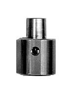


4 a) b) c) d) e) f) Figure 3 - Ultrasound probe evolution

.")


.")
5 2.2 The Signal Acquisition Equipment The first acquisition system was designed mainly for R&D and the use in the lab. The acquisition system consisted of a portable PC with a built-in pulser/receiver and an A/D converter (Figure 4a). Two extra connectors were added to the PC, one for the ultrasonic signal and another one to be able to externally trigger the acquisition system. Feedback from the industrial partner indicated that to be able to install the product at the plant, the acquisition system should be fixed in a work station on the production floor. With this idea in mind, the second version was designed as electronics box communicating with a PC through the parallel port (Figure 4b). Figure 4c shows the latest design which comprises a PC and electronics for ultrasonic scanning into a single unit. a) b) c) Figure 4 - Acquisition system evolution
; the quality of the weld was not assessed.")
6 2.2 Software and Communications The first software generation was designed to acquire and process individual weld scans for R&D purposes. The user was required to indicate when he was going to perform welding, the software only acquired and displayed the B-Scan (as explained in section 1.1); the quality of the weld was not assessed. For obvious reasons the software was not prepared to be integrated in production. To be practical enough, the software needed to perform continuous scanning, acquire the ultrasonic data every time when the external trigger was activated and display and save the quality evaluation of the weld. One of the main issues was that the software should be able to distinguish between different welds, therefore a communication between the software and the robot controller was needed. This communication was done using an external digital IO device. This device was connected to the PLC of the robot controller which indicated to our software the weld number the part number being welded. An example of a wiring schematic using this device can be found in section 3.3. All these requirements have been implemented in the second generation software. Now it was able to scan continuously and display on screen the quality of each weld with a green-yellow-red scheme indicating good, acceptable and bad quality as well as the part and the time when the weld was scanned. Figure 5 shows a screen shoot of the main window of the software. The software had a statistics module (Figure 6) where the user had access to the whole information of the welding process. The system had the ability of being controlled remotely from the local area network of the plant or anywhere in the world through internet. Figure 5 - Software screenshot One of the main drawbacks of this scheme was that in order to obtain the information of the welding process, the user needed to look at the screen of the software (locally or remotely) and also that each device was independent from each other, making the supervision of several welding robots a difficult task. To solve this issue the third software generation was

7 developed. In this generation the client-server methodology was implemented. In this scheme the device acquiring the ultrasonic signature of the weld (client) does not display the quality of the weld. Instead, the client acquires, process and stores the necessary information and updates a central database on the server. If several clients are installed, all the information is updated on the server. The statistics and monitoring software is installed on the server, the user is able to obtain global statistics or monitor each individual station (client) from the server software. 3. Installation of the System 3.1 Main Unit Figure 6 - Statistics module. The main unit is usually fixed next or inside of the robot controller. The unit is prepared to be fixed in any orientation (Figure 7) and designed to tolerate the harsh industrial environment (dust, high temperatures and electromagnetic noise). Figure 7 - Main unit installation


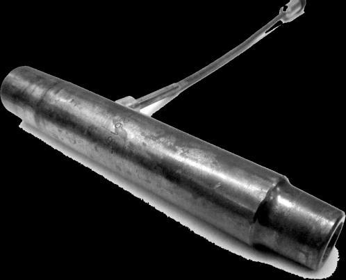
8 3.2 Ultrasonic Probe As was explained in section 2.1, the last generation ultrasonic transducer is built into the welding electrode. The installation of the transducer on the gun itself is exactly the same as for any other electrode. The inner water tube should be shortened to the length of the internal probe and the transducer/electrode should be inserted into the hex adaptor of the welding gun (Figure 8). Electrode cap installation and replacement is similar than with any other electrode. Once that the ultrasound transducer is installed, the next step is to run the coaxial cable provided with the system from the location of the main unit until the welding gun. Figure 8 - Ultrasonic probe installation 3.3 Communication with the Robot Controller The system is prepared to communicate with the most common network protocols (DeviceNet, Ethernet, etc) as well as with the most basic discrete IO communication. The system should be able to distinguish between different parts and welds, therefore the robot controller should send a signal to the system to indicate which part and weld is being processed. Once the quality evaluation has been performed the system provides feedback to the robot controller and informs the quality of the weld. Figure 9 shows an example for an 8 input and 8 output discrete IO communication. The robot controller sends the part number and weld number using 6 bits and the system provides the feedback to the robot controller using 5 bits. The communication protocol, number and configuration of bits depend totally on the application requirements.
9 weld weld weld weld trigger part part Robot Controller Digital IO Device USB RIWA PC bad good acceptable uncertain no read Figure 9 - Robot controller communication 4. Conclusions The system development is unimaginable without involvement of one or few industrial partners who help in transition of the new technology from the lab into production environment. The major steps of system evolution were presented together with the main installation stages required for the integration of the Real-Time Integrated Weld Analyzer (RIWA). The final version of the system consists of an ultrasonic probe built into the welding electrode and a robust independent main unit in charge of acquiring and processing the ultrasonic data to determine the quality of the weld. The installation and maintenance of the ultrasonic probe is similar to a regular welding electrode. Communication between the robot controller and the system can be achieved by any common network protocol as well as discrete IO. The system provides quality evaluation to 100% of the welds being produced by the robot. Since the quality of the weld is determined in real time, feedback provided by the system can be used to perform any action desired (send alerts, send notifications to maintenance personal, stop the production line, etc.). Communication between systems and a main server makes the monitoring of the whole production floor accessible in a single PC. The special software performs analysis and creates customized reports from the collected statistics.
10 Acknowledgements The authors would like to thank CONACYT for the financial support under scholarship References 1. A.A. Denisov, C.M. Shakarji, B.B.Lawford, R.Gr. Maev, J.M.Paille, Spot Weld Analysis with 2D Ultrasonic Array, Journal of Research of the National Institute of Standards and Technology, 109 (2): March-April S. I. Rokhlin, S. Meng, and L. Adler, In-process ultrasonic evaluation of spot welds, Mater. Eval., vol. 47, pp , J. E. Sutter, In-process ultrasonic weld inspection and adaptive control, Sheet Metal Welding Conf. XI, Sterling Heights, MI, May 11 14, R. P. Hurlebaus, Method of monitoring a welding operation, U.S. Patent 3,726,130, Dec. 9, T. Okuda and M. Inada, Ultrasonic testing method and apparatus for resistance welding, U.S. Patent 4,099,045, Nov. 29, R. Gr. Maev, A. Ptchelintsev. Monitoring of Pulsed Ultrasonic Waves Interaction With Metal Continuously Heated to the Melting Point, in Quantitative Non-destructive Evaluation-2000, edited by D. O. Thompson and D.E. Chimenti., AIP Conference Proceedings 557. Melville, New York, 2000, pp A. M. Chertov, R. Gr. Maev, Extraction of the Straight Line Segments from the Noisy Images as a Part of Pattern Recognition Procedure Proc. 5th International Workshop, Advances in Signal Processing for Non Destructive Evaluation of Materials Québec City (Canada),2-4 Aug
Automation Interface Requirements for J602 Basic I/O Interface of a DPC 4 Welding System
 - 1 - Automation Interface Requirements for J602 Basic I/O Interface of a DPC 4 Welding System The DPC 4 welding system offers several features that are intended to communicate with automation. These features
Perfecting the Package Bare and Overmolded Stacked Dies. Understanding Ultrasonic Technology for Advanced Package Inspection. A Sonix White Paper
 Perfecting the Package Bare and Overmolded Stacked Dies Understanding Ultrasonic Technology for Advanced Package Inspection A Sonix White Paper Perfecting the Package Bare and Overmolded Stacked Dies Understanding
THE NEW LASER FAMILY FOR FINE WELDING FROM FIBER LASERS TO PULSED YAG LASERS
 FOCUS ON FINE SOLUTIONS THE NEW LASER FAMILY FOR FINE WELDING FROM FIBER LASERS TO PULSED YAG LASERS Welding lasers from ROFIN ROFIN s laser sources for welding satisfy all criteria for the optimized laser
EDDYCHEK 5. Innovative eddy current testing for quality and process control. Touchscreen. Networking. All major applications.
 EDDYCHEK 5 Innovative eddy current testing for quality and process control All major applications 2 channel testing Touchscreen Reporting Networking Eddy current testing: essential Full-body testing with
NONDESTRUCTIVE INSPECTION OF A COMPOSITE MATERIAL SAMPLE USING A LASER ULTRASONICS SYSTEM WITH A BEAM HOMOGENIZER
 NONDESTRUCTIVE INSPECTION OF A COMPOSITE MATERIAL SAMPLE USING A LASER ULTRASONICS SYSTEM WITH A BEAM HOMOGENIZER J. M. S. Sakamoto 1, 4, A. Baba 2, B. R. Tittmann 3, J. Mulry 3, M. Kropf, 3 and G. M.
Contact data Anthony Lyons, AGELLIS Group AB, Tellusgatan 15, Lund, Sweden. Telefone:
 1 New measurement system on continuous casting tundishes at Steel of West Virginia provides true steel running level and increases yield by accurate drain control Authors M. Gilliam, P. Wolfe, J. Rulen,
PDV SYSTEM MODULAR. Product Information. Traverse Solutions & Instrumentation. Modular PDV System 2.0
 MODULAR PDV SYSTEM Product Information Traverse Solutions & Instrumentation Modular PDV System 2.0 TS&I MODULAR PDV SYSTEM 2.0 The TS&I Chassis can receive up to 8 PDV Modules. Easily remove the face plate
In-process inspection: Inspector technology and concept
 Inspector In-process inspection: Inspector technology and concept Need to inspect a part during production or the final result? The Inspector system provides a quick and efficient method to interface a
A dedicated data acquisition system for ion velocity measurements of laser produced plasmas
 A dedicated data acquisition system for ion velocity measurements of laser produced plasmas N Sreedhar, S Nigam, Y B S R Prasad, V K Senecha & C P Navathe Laser Plasma Division, Centre for Advanced Technology,
Tender Report for Supply and installation of LAN in *Biomedical Imaging and Bioinformatics Lab*
 Tender Report for Supply and installation of LAN in *Biomedical Imaging and Bioinformatics Lab* General Scope of Work: Supply and installation of Computer Laboratory setup in MIU Location of Installation:
CITOCUT Plasma inverter cutting range
 CITOCUT Plasma inverter cutting range Sword edge cutting www.oerlikon-welding.com The plasma expert advanced plasma cutting powerful all metals performance portable solutions inverter plasma gouging maintenance
Super Idea for Ultrasonic Inspection
 Super Idea for Ultrasonic Inspection Ultrasound Inspection Ultrasound phased array (PA) and Time Of Flight Diffraction (TOFD), two of the new NDT technologies, have become one important development trend
Ultrasonic Testing adapts to meet the needs of the Automotive Tube Industry
 Ultrasonic Testing adapts to meet the needs of the Automotive Tube Industry By Mark Palynchuk, Western Instruments Inc. Mill-Line Ultrasonic Testing (UT) has typically been limited to wall thicknesses
Minimize your cost for Phased Array & TOFD
 Minimize your cost for Phased Array & TOFD Latest ultrasonic flaw detector from SIUI, incorporates the latest advancements in Encoder In/Out UT/ TOFD Probe high-performance Phased Array and TOFD detection
Re: ENSC 370 Project Physiological Signal Data Logger Functional Specifications
 School of Engineering Science Simon Fraser University V5A 1S6 versatile-innovations@sfu.ca February 12, 1999 Dr. Andrew Rawicz School of Engineering Science Simon Fraser University Burnaby, BC V5A 1S6
MAXTECH, Inc. BRC-1000 Series. C-Band Redundant LNB Systems. Technology for Communications. System Block Diagrams
 MAXTECH, Inc. Technology for Communications BRC-1000 Series C-Band Redundant LNB Systems Introduction Redundant LNB systems minimize system downtime due to LNB failure by providing a spare LNB and an automatic
V9A01 Solution Specification V0.1
 V9A01 Solution Specification V0.1 CONTENTS V9A01 Solution Specification Section 1 Document Descriptions... 4 1.1 Version Descriptions... 4 1.2 Nomenclature of this Document... 4 Section 2 Solution Overview...
Interactive Virtual Laboratory for Distance Education in Nuclear Engineering. Abstract
 Interactive Virtual Laboratory for Distance Education in Nuclear Engineering Prashant Jain, James Stubbins and Rizwan Uddin Department of Nuclear, Plasma and Radiological Engineering University of Illinois
SHARP Plasma inverter cutting range
 SHARP Plasma inverter cutting range Sword edge cutting www.cemont.com The plasma expert advanced powerful all metals performance portable solutions plasma gouging maintenance high quality The plasma process
CIRCOGRAPH. Non-Destructive Eddy Current Testing of Long Products such as Wires, Bars and Tubes
 CIRCOGRAPH Non-Destructive Eddy Current Testing of Long Products such as Wires, Bars and Tubes FOERSTER DIVISION TEST SYSTEMS (TS) The Company FOERSTER is a global technology leader for nondestructive
PRESTOJET Plasma inverter cutting range
 PRESTOJET Plasma inverter cutting range Sword edge cutting www.saf-fro.com The plasma expert advanced powerful all metals performance portable solutions inverter plasma gouging maintenance high quality
MS2540 Current Loop Receiver with RS485 Communication
 MS2540 Current Loop Receiver with RS485 Communication User Manual Metal Samples Company A Division of Alabama Specialty Products, Inc. 152 Metal Samples Rd., Munford, AL 36268 Phone: (256) 358 4202 Fax:
Configuring the Stack ST8961 VS Module when used in conjunction with a Stack ST81xx series display.
 Configuring the Stack ST8961 VS Module when used in conjunction with a Stack ST81xx series display. Your Stack ST8961 VS module allows you to synchronize, overlay, and record data available on your Stack
Samsara VS2 Series Vision System
 Samsara VS2 Series Vision System CLOUD-MANAGED VS2 VISION SYSTEM DATASHEET Samsara s VS2-series machine vision system combines next-generation processing power with builtin cloud storage and reporting
G4500. Portable Power Quality Analyser. Energy Efficiency through power quality
 G4500 Portable Power Quality Analyser Energy Efficiency through power quality The BlackBox portable series power quality analyser takes power quality monitoring to a whole new level by using the revolutionary
PRACTICAL APPLICATION OF THE PHASED-ARRAY TECHNOLOGY WITH PAINT-BRUSH EVALUATION FOR SEAMLESS-TUBE TESTING
 PRACTICAL APPLICATION OF THE PHASED-ARRAY TECHNOLOGY WITH PAINT-BRUSH EVALUATION FOR SEAMLESS-TUBE TESTING R.H. Pawelletz, E. Eufrasio, Vallourec & Mannesmann do Brazil, Belo Horizonte, Brazil; B. M. Bisiaux,
Stud Welding Equipment
 Stud Welding Equipment 10/16 N550c Arc Charger Breakthrough Charger design provides powerful 550A Arc Welder from 120V wall outlet! The N550c Arc Charger is the first of a revolutionary new class of stud
John H. Gieske and Mark A Rumsey Sandia National Laboratories Albuquerque, New Mexico This work was supported by the United States
 ve Nondestructive Evaluation (NDE) of Composite-to-Metal Bond Interface of Turbine Blade Using An Acousto-Ultrasonic Technique. John H. Gieske and Mark A Rumsey Sandia National Laboratories Albuquerque,
Integration of Virtual Instrumentation into a Compressed Electricity and Electronic Curriculum
 Integration of Virtual Instrumentation into a Compressed Electricity and Electronic Curriculum Arif Sirinterlikci Ohio Northern University Background Ohio Northern University Technological Studies Department
Trusted 40 Channel 120 Vac Digital Input FTA
 ICSTT-RM290F-EN-P (PD-T8824) Trusted Product Overview The Trusted 40 Channel 120 Vac Digital Input Field Termination Assembly (FTA) T8824 is designed to act as the main interface between a field device
Engineered to meet your needs T he oldest name in stud welding,
 Engineered to meet your needs T he oldest name in stud welding, Nelson Stud Welding Inc., continues it s leadership role into the 21st century with the introduction of a full line of new drawn-arc welding
Quality Assurance Tools Post Installation Self-Compliance
 August 30, 2017 Burbank, CA Sophia Antipolis, FR Quality Assurance Tools Post Installation Self-Compliance +1 818 877-6149 The DCinemaCompliance Group, is pleased to announce the availability of the Digital
Pulse Generator for the Industry. Transit Time Sensors from wenglor
 Pulse Generator for the Industry Transit Time Sensors from wenglor Pioneering in the Field of Optical Sensor Technology WinTec: wenglor Innovation As an internationally established technology leader for
T3316 IP QAM Modulator User Manual
 T3316 IP QAM Modulator User Manual SW Version: 1.02 HW version: 0.70.0.0 Web NMS version: 1.02 Intended Audience About This Manual This user manual has been written to help people who have to use, to integrate
FEASIBILITY STUDY OF USING EFLAWS ON QUALIFICATION OF NUCLEAR SPENT FUEL DISPOSAL CANISTER INSPECTION
 FEASIBILITY STUDY OF USING EFLAWS ON QUALIFICATION OF NUCLEAR SPENT FUEL DISPOSAL CANISTER INSPECTION More info about this article: http://www.ndt.net/?id=22532 Iikka Virkkunen 1, Ulf Ronneteg 2, Göran
CITOCUT Plasma inverter cutting range
 CITOCUT Plasma inverter cutting range Sword edge cutting www.oerlikon-welding.com The plasma expert advanced powerful all metals performance portable solutions inverter plasma gouging maintenance high
Ku-Band Redundant LNB Systems. 1:1 System RF IN (WR75) TEST IN -40 db OFFLINE IN CONTROLLER. 1:2 System POL 1 IN (WR75) TEST IN -40 db POL 2 IN
 TEST IN -40 db OFFLINE IN CONTROLLER. 1:2 System POL 1 IN (WR75) TEST IN -40 db POL 2 IN") BRK-1000 Series Ku-Band Redundant LNB Systems Introduction Redundant LNB systems minimize system downtime due to LNB failure by providing a spare LNB and an automatic means of switching to the spare upon
BRK-1000 Series Ku-Band Redundant LNB Systems Introduction Redundant LNB systems minimize system downtime due to LNB failure by providing a spare LNB and an automatic means of switching to the spare upon
Enhanced Diagnostics through Ultrasound Imaging
 Enhanced Diagnostics through Ultrasound Imaging Mark Goodman, VP Engineering Presented by: Adrian Messer UE Systems, Inc. Ph: 914-592-1220 / 800-223-1325 Fax: 914-347-2181 Web: www.uesystems.com Email:
Digital Video Engineering Professional Certification Competencies
 Digital Video Engineering Professional Certification Competencies I. Engineering Management and Professionalism A. Demonstrate effective problem solving techniques B. Describe processes for ensuring realistic
PRELIMINARY INFORMATION. Professional Signal Generation and Monitoring Options for RIFEforLIFE Research Equipment
 Integrated Component Options Professional Signal Generation and Monitoring Options for RIFEforLIFE Research Equipment PRELIMINARY INFORMATION SquareGENpro is the latest and most versatile of the frequency
Installation / Set-up of Autoread Camera System to DS1000/DS1200 Inserters
 Installation / Set-up of Autoread Camera System to DS1000/DS1200 Inserters Written By: Colin Langridge Issue: Draft Date: 03 rd July 2008 1 Date: 29 th July 2008 2 Date: 20 th August 2008 3 Date: 02 nd
OEM Basics. Introduction to LED types, Installation methods and computer management systems.
 OEM Basics Introduction to LED types, Installation methods and computer management systems. v1.0 ONE WORLD LED 2016 The intent of the OEM Basics is to give the reader an introduction to LED technology.
Scope of the art Scope Rider Handheld digital oscilloscope
 Scope of the art Scope Rider Handheld digital oscilloscope Lab performance in a rugged and portable design 60 MHz to 500 MHz Isolated, CAT IV Invest 2 minutes and you ll never look back. Scope Rider Experience
NDT Applications of All-Electronic 3D Terahertz Imaging
 Introduction NDT Applications of All-Electronic 3D Terahertz Imaging Stefan BECKER *, Andreas Keil *, Heinrich Nolting * * Becker Photonik GmbH, D-32457 Porta Westfalica, Germany! Basics of All-Electronic
NDT Supply.com P.O. BOX 7350 Shawnee Mission, KS USA
 NDT Technologies, Inc. Wire Rope Inspection Using proven MFL Technology. NDT Technologies has over 30 years of experience dedicated to developing and improving Wire Rope Inspection equipment and methods.
The Syscal family of resistivity meters. Designed for the surveys you do.
 The Syscal family of resistivity meters. Designed for the surveys you do. Resistivity meters may conveniently be broken down into several categories according to their capabilities and applications. The
DX3316 IP QAM Modulator User Manual
 DX3316 IP QAM Modulator User Manual SW Version: 1.02 HW version: 0.70.0.0 Web NMS version: 1.02 DEXIN DIGITAL TECHNOLOGY 20142014 CORP. LTD. Intended Audience About This Manual This user manual has been
Condition Monitoring Custom Products
 Features: CMCP500 Series Transmitters World s Most Popular HMI Machine Mimics Historical and Real Time Trending Current and Historical Alarm Lists Standard MODBUS A to D Converter Other Protocols Optional
Operating Instructions
 CNTX Contrast sensor Operating Instructions CAUTIONS AND WARNINGS SET-UP DISTANCE ADJUSTMENT: As a general rule, the sensor should be fixed at a 15 to 20 angle from directly perpendicular to the target
New appraoch for X-ray weld inspection of pipeline segments
 New appraoch for X-ray weld inspection of pipeline segments Lennart Schulenburg VisiConsult X-ray Systems & Solutions GmbH 1 Overview Weld inspection in heavy industries ( Pipe and Tank ) Analogue Film
arxiv:hep-ex/ v1 27 Nov 2003
 arxiv:hep-ex/0311058v1 27 Nov 2003 THE ATLAS TRANSITION RADIATION TRACKER V. A. MITSOU European Laboratory for Particle Physics (CERN), EP Division, CH-1211 Geneva 23, Switzerland E-mail: Vasiliki.Mitsou@cern.ch
ThinkRF D GHz RF Downconverter
 Product Brochure and Technical Datasheet ThinkRF D2030 27-30 GHz RF Downconverter Extend your existing 3G/4G test equipment to 5G Features and Benefits Compact, low-power, portable and cost-effective Retain
Live events staging. Media centers
 Christie Spyder X80 80 megapixel, true 4K@60Hz performance across multiple displays Auditoriums Control rooms Live events staging Post-production Broadcast studios Corporate lobbies Media centers Sports
DT9834 Series High-Performance Multifunction USB Data Acquisition Modules
 DT9834 Series High-Performance Multifunction USB Data Acquisition Modules DT9834 Series High Performance, Multifunction USB DAQ Key Features: Simultaneous subsystem operation on up to 32 analog input channels,
Photonics solutions For innovative photonics
 Photonics solutions For innovative photonics 2013 Catalog PRODUCTS CATALOG 2013 A word from us... 1 AnyWave Fiberbench Speckle Scrambler... 2 Polarization control... 5 Hi resolution Polarization control...
APPLICATION OF PHASED ARRAY ULTRASONIC TEST EQUIPMENT TO THE QUALIFICATION OF RAILWAY COMPONENTS
 APPLICATION OF PHASED ARRAY ULTRASONIC TEST EQUIPMENT TO THE QUALIFICATION OF RAILWAY COMPONENTS K C Arcus J Cookson P J Mutton SUMMARY Phased array ultrasonic testing is becoming common in a wide range
Practical Application of the Phased-Array Technology with Paint-Brush Evaluation for Seamless-Tube Testing
 ECNDT 2006 - Th.1.1.4 Practical Application of the Phased-Array Technology with Paint-Brush Evaluation for Seamless-Tube Testing R.H. PAWELLETZ, E. EUFRASIO, Vallourec & Mannesmann do Brazil, Belo Horizonte,
Steam Generator Tube Inspection I
 Steam Generator Tube Inspection I Development of Smart Array Probe and Introduction of New Inspection System K. Maeda, J. Shimone, A. Nunoko, J. Akagawa, Y. Nagata, H. Izumida, Y. Harada, Nuclear Engineering,
AUTOMATIC VIDEO LOSS A/B SWITCH
 CG-X AUTOMATIC VIDEO LOSS A/B SWITCH INSTRUCTION BOOK IB647502 TABLE OF CONTENTS DESCRIPTION 2 MOUNTING INSTRUCTIONS 3 HOW TO CABLE THE CG-X 3 POWER SUPPLY INSTALLATION 3 OPERATION 3 CARE AND MAINTENANCE
Porta-Person: Telepresence for the Connected Conference Room
 Porta-Person: Telepresence for the Connected Conference Room Nicole Yankelovich 1 Network Drive Burlington, MA 01803 USA nicole.yankelovich@sun.com Jonathan Kaplan 1 Network Drive Burlington, MA 01803
VERWER TRAINING AND CONSULTANCY LTD Supporting the PROFIBUS Group UK & PROFIBUS International
 VERWER TRAINING AND CONSULTANCY LTD Supporting the PROFIBUS Group UK & PROFIBUS International Web: www.verwertraining.com, Email: enquiries@verwertraining.com Tutorial What can I do with ProfiTrace 2?
MTL Software. Overview
 MTL Software Overview MTL Windows Control software requires a 2350 controller and together - offer a highly integrated solution to the needs of mechanical tensile, compression and fatigue testing. MTL
Design and Realization of the Guitar Tuner Using MyRIO
 Journal of Automation and Control, 2017, Vol. 5, No. 2, 41-45 Available online at http://pubs.sciepub.com/automation/5/2/2 Science and Education Publishing DOI:10.12691/automation-5-2-2 Design and Realization
An Overview of Beam Diagnostic and Control Systems for AREAL Linac
 An Overview of Beam Diagnostic and Control Systems for AREAL Linac Presenter G. Amatuni Ultrafast Beams and Applications 04-07 July 2017, CANDLE, Armenia Contents: 1. Current status of existing diagnostic
EAN-Performance and Latency
 EAN-Performance and Latency PN: EAN-Performance-and-Latency 6/4/2018 SightLine Applications, Inc. Contact: Web: sightlineapplications.com Sales: sales@sightlineapplications.com Support: support@sightlineapplications.com
WELDING CONTROL UNIT: TE 450 USER MANUAL
 j WELDING CONTROL UNIT: TE 450 USER MANUAL RELEASE SOFTWARE No. 1.50 DOCUMENT NUMBER: MAN 4097 EDITION: MARCH 1998 This page is left blank intentionally. 2 / 34 TABLE OF CONTENTS SUBJECTS PAGE WELDING
Random Access Scan. Veeraraghavan Ramamurthy Dept. of Electrical and Computer Engineering Auburn University, Auburn, AL
 Random Access Scan Veeraraghavan Ramamurthy Dept. of Electrical and Computer Engineering Auburn University, Auburn, AL ramamve@auburn.edu Term Paper for ELEC 7250 (Spring 2005) Abstract: Random Access
Detailed Design Report
 Detailed Design Report Chapter 4 MAX IV Injector 4.6. Acceleration MAX IV Facility CHAPTER 4.6. ACCELERATION 1(10) 4.6. Acceleration 4.6. Acceleration...2 4.6.1. RF Units... 2 4.6.2. Accelerator Units...
SPECIFICATION NO NOTE
 NOTE The Model 207-1 is a special version of the standard M-207 Power Supply. It has been altered for a special applications requiring low current operation at high arc voltages in ambient and pressurized
LPX Platform LPX Platform
 LPX Platform LPX Platform Ultrasonic Welding Systems for Low Power Applications Advanced-Performance Features for Process Control and Reliable Power User Interface/Process Controls Digital parameter entry
PITZ Introduction to the Video System
 PITZ Introduction to the Video System Stefan Weiße DESY Zeuthen June 10, 2003 Agenda 1. Introduction to PITZ 2. Why a video system? 3. Schematic structure 4. Client/Server architecture 5. Hardware 6. Software
Smart Traffic Control System Using Image Processing
 Smart Traffic Control System Using Image Processing Prashant Jadhav 1, Pratiksha Kelkar 2, Kunal Patil 3, Snehal Thorat 4 1234Bachelor of IT, Department of IT, Theem College Of Engineering, Maharashtra,
TransitHound Cellphone Detector User Manual Version 1.3
 TransitHound Cellphone Detector User Manual Version 1.3 RF3 RF2 Table of Contents Introduction...3 PC Requirements...3 Unit Description...3 Electrical Interfaces...4 Interface Cable...5 USB to Serial Interface
INSTRUCTION MANUAL. J800 Weld Controller. 3/25/2018 Revision
 INSTRUCTION MANUAL J800 Weld Controller 3/25/2018 Revision 1.1.1.1 THIS PAGE IS INTENTIONALLY LEFT BLANK ii INSTALLATION AND OPERATION Janda Company, Inc. J800 WELDING CONTROLLER TO END USERS: This Weld
SPECIFICATION NO Model 207 Automatic GTAW Welding System
 1.0 Introduction The Model 207 is a completely self-contained Gas Tungsten Arc Welding (GTAW) System requiring only input power, inert gas and AMI Welding Head (or manual torch) for operation. Its small
Homework 6 March 23, 2013
 Homework 6 March 23, 2013 CPE-322, Engineering Design VI A collaborative effort on behalf of Robert Stephenson I pledge my Honor that I have abided by the Stevens Honor System. Robert Stephenson Section
A Turnkey Weld Inspection Solution Combining PAUT & TOFD
 11th European Conference on Non-Destructive Testing (ECNDT 2014), October 6-10, 2014, Prague, Czech Republic A Turnkey Weld Inspection Solution Combining PAUT & TOFD Jérôme POIRIER 1, Patrick TREMBLAY
Copyright 2018 Xi an NovaStar Tech Co., Ltd. All Rights Reserved. No part of this document may be copied, reproduced, extracted or transmitted in any
 MCTRL4K Independent Controller Product Version: Document Number: V1.0.3 NS110100428 Copyright 2018 Xi an NovaStar Tech Co., Ltd. All Rights Reserved. No part of this document may be copied, reproduced,
Trusted 40 Channel 120 Vac Digital Input FTA
 PD-T8824 Trusted Trusted 40 Channel 120 Vac Digital Input FTA Product Overview The Trusted 40 Channel 120 Vac Digital Input Field Termination Assembly (FTA) T8824 is designed to act as the main interface
THE EFFECT OF LOOSE CONNECTORS ON SHIELDING EFFECTIVENESS
 THE EFFECT OF LOOSE CONNECTORS ON SHIELDING EFFECTIVENESS Asheridge Communications (A Teleste PLC Company) has undertaken a study to further understand the issues of RFI (Radio Frequency Interference)
Automatic Defect Recognition in Industrial Applications
 Automatic Defect Recognition in Industrial Applications Klaus Bavendiek, Frank Herold, Uwe Heike YXLON International, Hamburg, Germany INDE 2007 YXLON. The reason why 1 Different Fields for Usage of ADR
PRELIMINARY Sunny Boy 240-US
 PRELIMINARY Sunny Boy 240-US SB 240-US-10 Optimized reliability Simple installation Unrivaled monitoring SMA-backed security Multigate technology allows for reduced component count Private band powerline
B. The specified product shall be manufactured by a firm whose quality system is in compliance with the I.S./ISO 9001/EN 29001, QUALITY SYSTEM.
 VideoJet 8000 8-Channel, MPEG-2 Encoder ARCHITECTURAL AND ENGINEERING SPECIFICATION Section 282313 Closed Circuit Video Surveillance Systems PART 2 PRODUCTS 2.01 MANUFACTURER A. Bosch Security Systems
Content. Solutions for MRI. Medical electronic Connectors
 Content 1 Solutions for MRI 2 Medical electronic Connectors Some Characteristics often found in Medical Electronic Equipment Customized for Function Customized for design Non Magnetic High mating cycles
PERFORMANCE SPECIFICATION SHEET CONNECTORS, PLUGS, ELECTRICAL, COAXIAL RADIO FREQUENCY, (SERIES BNC (CABLED), PIN CONTACT, CLASS 2)
, PIN CONTACT, CLASS 2)") INCH-POUND MIL-PRF-39012/16H 16 November 2006 SUPERSEDING MIL-PRF-39012/16G 26 September 1994 PERFORMANCE SPECIFICATION SHEET CONNECTORS, PLUGS, ELECTRICAL, COAXIAL RADIO FREQUENCY, (SERIES BNC (CABLED),
INCH-POUND MIL-PRF-39012/16H 16 November 2006 SUPERSEDING MIL-PRF-39012/16G 26 September 1994 PERFORMANCE SPECIFICATION SHEET CONNECTORS, PLUGS, ELECTRICAL, COAXIAL RADIO FREQUENCY, (SERIES BNC (CABLED),
SAL Series Wireless Clock (V1)
") SAL Series Wireless Clock (V1) HIGHLIGHTS Microprocessor based movement Each clock acts as a repeater and transmitter 915 928MHz frequency hopping technology Receiving and transmission rate every four
SAL Series Wireless Clock (V1) HIGHLIGHTS Microprocessor based movement Each clock acts as a repeater and transmitter 915 928MHz frequency hopping technology Receiving and transmission rate every four
Installation of a DAQ System in Hall C
 Installation of a DAQ System in Hall C Cuore Collaboration Meeting Como, February 21 st - 23 rd 2007 S. Di Domizio A. Giachero M. Pallavicini S. Di Domizio Summary slide CUORE-like DAQ system installed
Customer Responsibilities. Important Customer Information. Agilent InfinityLab LC Series Site Preparation Checklist
 Agilent Site Preparation InfinityLab Checklist LC Series Thank you for purchasing an Agilent instrument. To get you started and to assure a successful and timely installation, please refer to this specification
A New "Duration-Adapted TR" Waveform Capture Method Eliminates Severe Limitations
 31 st Conference of the European Working Group on Acoustic Emission (EWGAE) Th.3.B.4 More Info at Open Access Database www.ndt.net/?id=17567 A New "Duration-Adapted TR" Waveform Capture Method Eliminates
Document History Version Comment Date
 FAQ Inspector 2 (12) Document History Comment Date 1.04 Created 2008-09-11 Corrected the headline of S03 issue and the title name in the global header field 3 (12) Table Of Contents DOCUMENT HISTORY...
LASER. Laser-Position-Transducer. LLD-150 Series. Key-Features:
 LASER Laser-Position-Transducer LLD-150 Series Key-Features: Content: Technical Data.2 Technical Drawings...2 Types Of Output...3 Configuration Software...4 Order Code...5 Options & Accessories.5 - Measurement
Preventing Fieldbus Physical Layer Problems
 Preventing Fieldbus Physical Layer Problems 1 Introduction Foundation Fieldbus is highly reliable when correctly installed and maintained. The key is in knowing what must be done to start with and to maintain
Team Members: Erik Stegman Kevin Hoffman
 EEL 4924 Electrical Engineering Design (Senior Design) Preliminary Design Report 24 January 2011 Project Name: Future of Football Team Name: Future of Football Team Members: Erik Stegman Kevin Hoffman
COLOUR CHANGING USB LAMP KIT
 TEACHING RESOURCES SCHEMES OF WORK DEVELOPING A SPECIFICATION COMPONENT FACTSHEETS HOW TO SOLDER GUIDE SEE AMAZING LIGHTING EFFECTS WITH THIS COLOUR CHANGING USB LAMP KIT Version 2.1 Index of Sheets TEACHING
BLINKIN LED DRIVER USER'S MANUAL. REV UM-0 Copyright 2018 REV Robotics, LLC 1
 fg BLINKIN LED DRIVER USER'S MANUAL REV-11-1105-UM-0 Copyright 2018 REV Robotics, LLC 1 TABLE OF CONTENTS 1 OVERVIEW... 3 1.1 CONNECTIONS... 3 1.2 KIT CONTENTS... 3 1.3 ELECTRICAL RATINGS... 3 1.4 SUPPORTED
NOTICE: This document is for use only at UNSW. No copies can be made of this document without the permission of the authors.
 Brüel & Kjær Pulse Primer University of New South Wales School of Mechanical and Manufacturing Engineering September 2005 Prepared by Michael Skeen and Geoff Lucas NOTICE: This document is for use only
DX-10 tm Digital Interface User s Guide
 DX-10 tm Digital Interface User s Guide GPIO Communications Revision B Copyright Component Engineering, All Rights Reserved Table of Contents Foreword... 2 Introduction... 3 What s in the Box... 3 What
Henkel Installation Handbook LINEGUARD 2001
 Henkel Installation Handbook LINEGUARD 2001 HENKEL ITALIA S.r.l. Microprocessor instruments Henkel Installation Handbook Lineguard 2001 Page 2 Summary 1. The Microprocessor Instruments... 4 1.1. Norms
EZCOM-1. PLC - to - AMS MESSAGE DISPLAY INTERFACE INSTALLATION AND OPERATING INSTRUCTIONS. Rev March, 2001
 EZCOM-1 PLC - to - AMS MESSAGE DISPLAY INTERFACE INSTALLATION AND OPERATING INSTRUCTIONS Rev 1.3 - March, 2001 CONTENTS Page INTRODUCTION 1 SPECIFICATIONS 1 LIST OF SUPPLIED ITEMS 1 INSTALLATION & TESTING
Using DLP LightCrafter 4500 Triggers to Synchronize Cameras to Patterns
 Application Report Using DLP LightCrafter 4500 Triggers to Synchronize Cameras to ABSTRACT This document describes how to use the DLP LightCrafter 4500 with the global trigger function of industrial USB