PHABRIX. PHABRIX Qx Operation Manual. broadcast excellence. Software Release Manual Revision 4 PHQX-01, PHQX-01E. Copyright PHABRIX Ltd 2017
|
|
|
- Amos Lester
- 6 years ago
- Views:
Transcription


1 PHABRIX broadcast excellence Software Release Manual Revision 4 G QX PHQX-01, PHQX-01E Copyright PHABRIX Ltd 2017
2 About this Manual Notice The information in this document has been produced by PHABRIX Ltd with care and is believed to be accurate. PHABRIX Ltd does not assume responsibility for loss or damage resulting from errors, omissions or inaccuracies herein. This document is subject to change and revisions may be made and issued to include such changes. No part of this document may be reproduced, stored in a retrieval system or transmitted in any form or by any means, electronic, mechanical, recorded or otherwise without the prior written consent of PHABRIX Ltd. Copyright PHABRIX Ltd. All rights reserved. Software products licensed are owned by PHABRIX Ltd and are protected by international treaty provisions and national copyright laws. HDMI is the registered trademark of HDMI Licensing and is used within the document for identification purposes only. Revision This manual is a revision controlled document. Any changes to any page content will be reflected in the overall revision status of the whole manual. Release Date Software Version Comment 1 23 Jan First release of manual 2 21 Mar Addition of Waveform, Vectorscope, HDMI audio and new video standards 3 20 Jun Reference locking support with Output offset adjustment. Input timing against reference with Input Measurement Offset Aug HDR Heat-map, CIE 1931 x y Chart, HDR/WCG additions for Waveform and Vectorscope, and new PQ video standards. REST API for remote control and automation. CRC Analysis frame change detection added. PHABRIX Limited Omega House, Enterprise Way, Thatcham, Berkshire RG19 4AE United Kingdom phone + 44 (0) info@phabrix.com Page II

3 Getting Started Package Contents The shipping box should contain the following PHABRIX Qx unit: PHQX-01 or PHQX-01E (with Physical Layer Analysis) Power Supply Unit Mains lead General Safety Avoiding Personal Injury Power Supply This instrument is designed for use by qualified personnel only. No user serviceable parts are provided. Units should be returned to your local PHABRIX agent for servicing. The Operator should NOT remove the case from the unit. Do not spill any liquid onto the unit or its power adaptor. Make sure that the unit is connected to the correct power supply voltage. A power supply adaptor is supplied with the unit which may be connected to any AC power supply between 100 and 240VAC at 50-60Hz. Only the supplied power adaptor should be used with the unit. Do not use a damaged AC cable with the unit as it may cause a shock or fire hazard. Replacement AC cables are available from your local PHABRIX agent. How to upgrade software New software releases will be made available regularly as the product develops. Software downloads are approximately 100 MB and can be found in the Support area of the PHABRIX website currently located at Download the file to any FAT32 formatted USB stick. Make sure the unit is turned OFF before upgrading. Insert the USB into the front panel USB port. Press the start button TWICE in succession. The start button will glow pink when the upgrade procedure begins. If the button doesnt glow pink then repeat the procedure. The start button will flash several colours and the fans will be on full throughout the upgrade process. Please wait approximately 4 minutes as the unit upgrades. It will automatically show the menu screen when complete. Page III
4 Installation Environment Operating Temperature The unit should only be operated between 0 and 40 Celsius. If the unit is operated at a higher temperature there is a possibility of a fire hazard. If the temperature is changed rapidly from a cold environment to a hot environment, moisture can be created internally which can cause malfunction or damage the unit. Allow the unit to sit for 30 minutes without power applied to reduce any possibility of condensation. If the internal temperature rises above 65 Celsius the unit will turn OFF automatically. Input/Output Terminals Do not connect the input or output BNC connectors to external power as this can damage the internal circuitry and cause the unit to work incorrectly. The BNC connectors fitted on this unit are 75Ω type which are not compatible with 50Ω plugs. The use of 50Ω plugs will permanently damage the connectors on the unit. The use of 50Ω plugs is considered to be misuse of the equipment and will therefore invalidate the unit s warranty. When Not In Use Disconnect the unit from the power supply and AC power source when not in use. Maintenance Wipe the case gently with a soft cloth, lightly dampened with a neutral cleaning agent. Remove the power supply from the unit and turn OFF before cleaning. Do not allow any water or other liquid to enter the unit while cleaning. RoHS Compliance PHABRIX products are designed and manufactured using only RoHS compliant components and materials. Therefore based on information provided by our suppliers, PHABRIX certifies that ALL products that it manufactures are RoHS-5 compliant and that they do not exceed the designated levels of lead, cadmium, mercury, hexavalent chromium, polybrominated biphenyl (PBB) and polybrominated diphenyl ether flame retardants (PBDE) legislated under the provisions of the European Parliament and Council Directive on the Restriction of the Use of Certain Hazardous Substances in Electrical and Electronic Equipment (2011/65/EC) and associated regulations collective known as the RoHS Regulations. Disposal of Equipment This product is subject to the European WEEE (Waste Electrical and Electronic Equipment) directive and should be disposed of according to the regulations of each country. Page IV
5 Contents Getting Started III Package Contents... III General Safety... III Avoiding Personal Injury... III Power Supply... III How to upgrade software... III Installation Environment...IV Operating Temperature...IV Input/Output Terminals...IV When Not In Use...IV Maintenance...IV RoHS Compliance...IV Disposal of Equipment...IV Icon display and meaning...vii Overview 1 Start up... 1 Installation... 1 Analyser SDI connections... 1 Generator SDI connections... 2 Powering up the Qx... 2 Menu selection... 2 Instrument Launch Menu... 2 Instrument Description 5 Generator - Configuration... 6 Pathological signal insertion... 7 Output offset adjustment... 7 Generator - Status... 8 System IO (SDI)... 9 Analyser - Configuration Stats - SDI In A, B, C, D Analyser - Picture Blanking Area HDR Heat-map (False Colour Overlay) Transfer Curve and Colourimetry Overrides Analyser - CIE Chart Analyser - Waveform Analyser - Vectorscope Eye - SDI in A (PHQX-01E only) Jitter - SDI In A (PHQX-01E only) Analyser - Dataview Page V
6 Timing and System Reference System Reference Lock SDI A vs System Reference Input Measurement Offset SDI Co-Timing Analyser - Ancillary Status Analyser - Audio Meters Analyser - CRC Analysis Event Logging Network Status REST API Requests Time and NTP Specifications On-going Development Supported SDI standards Page VI

7 Icon display and meaning Eye - SDI In A Generator - Configuration Jitter - SDI In A Generator - Status System IO (SDI) Event Logging Stats - SDI In A Network Status Stats - SDI In B Stats - SDI In C Stats - SDI In D Timing and System Reference Analyser - Configuration Analyser - Ancillary Status Analyser - Audio Meters Analyser - CIE Chart Analyser - CRC Errors Analyser - Dataview Analyser - Picture Analyser - Vectorscope Analyser - Waveform Page VII

8 Overview Start up Generator 12G/6G/3G/HD BNC x4 Analyser inputs 12G/6G/3G/HD BNC x4 12G/6G/3G/HD Eye (SFP+) MSA/NON-MSA 12Gbps copper or fibre, 10G Ethernet Power 10-18v Networking 10/100/1000BASE-T 2x USB 2.0 SDI instrument output Ref loop BNC x 2 Micro USB (Factory service) HDMI instrument output (to 1080p60) Stereo Audio out, LTC in, 8x GPI I/O, 4x AES I/O Installation The rear of the unit shown above describes the connections and interfaces of the Qx. Before turning on the Qx, make sure the following connections are in place: The XLR power cable is inserted. For instrument display connect a suitable 1920 x 1080 capable monitor to either the HDMI instrument output or the SDI instrument output. The monitor output can be configured for 1080p60, 1080p59.94 or 1080p50 frame rates using Display Options submenu of the Instrument Launch Menu. For mouse and keyboard control, the two USB ports at the rear of the unit should be used. Note: The following interfaces are temporarily unavailable in this release of software: SFP A and SFP B LTC In GPI I/O AES I/O Analyser SDI connections Analyser The Physical Layer connection for eye and jitter outlined in red is the furthest right BNC with a red nut. This provides the multi rate eye and jitter connection from HD-SDI to 12G-SDI. There are four 12G-SDI capable input BNC s for the analyser SDI IN A, B, C, D. Up to four SDI inputs may be connected at any one time however the system will automatically determine the signal set to analyse be it single link, dual link or quad link based on the SMPTE ST 352 packets present. The algorithm looks to SDI IN A first and then determines the overall standard. If the SMPTE ST 352 packets are known to be incorrect then the user has the option to select Ignore payload identifier packets (ST 352) in the Analyser Configuration window. Page 1


9 Generator SDI connections The generator provides up to four SDI output signals which must form part of the same video signal set e.g. 12G payload using four 3G-SDI outputs or 12G payload using two 6G-SDI signals. SDI OUT A is always present and carries the first signal in the group. SDI OUT B is active for dual link standards and SDI OUT C and SDI OUT D are active for quad link standards. Powering up the Qx When the Power Button on the Qx is first pressed, the unit fans will cycle for seconds at high speed as the system boots then settle to their normal operating speed. Power Button USB port Menu selection The following menu screen will be displayed after power up: To activate the Instrument Launch Menu left click the PHABRIX symbol on the Instrument Bar To hide the Instrument Bar left click within its blank area Bringing the cursor to the bottom of screen re-enables the Instrument Bar Instrument Launch Menu Page 2

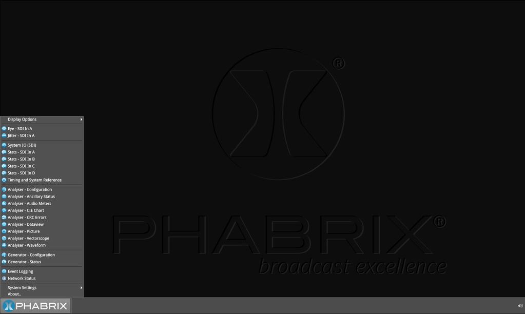
10 Page 3

11 As each instrument is selected, an icon will be placed on the Instrument Bar. The instrument and icon will be assigned a colour. Each icon will glow in the assigned colour to indicate if it is part of a group of instruments related to analyser, generator, or system. Instruments automatically group by colour. If one instrument is placed next to another then the border will outline all instruments of a common group in contact with each other to aid group recognition. Each instrument also has a sub menu. The sub menu is activated by right clicking the mouse in the window enabling a drop down configuration menu. Click and drag on the grey bar at the top of the sub menu to move it. In addition to window specific commands, the option to Close the instrument is provided in its sub menu. Double clicking within a window will cycle through a set of standard instrument sizes. In many cases the size of a window can be further adjusted to suit requirements. Click and drag on an instrument s surface to reposition the instrument. Page 4


12 Example of drop down menu on right mouse click: right click mouse for additional drop down menus Instrument Description The guide that follows is intended as an introduction to the menu selection and the tool-set. The Qx has the advantage of being a generator and an analyser so this tour of the product will be using both toolsets simultaneously. For this guide we will assume that you have connected the unit to itself as shown in the following diagram. Connect generator to analyser SDI OUT (Generator) SDI IN (Analyser) Page 5

13 Generation Generator - Configuration The Generator Configuration window is used to select the generator video standard and test pattern. Once selected the new test signal is loaded by pressing the Generate pane. Note: In this software revision the generator takes approximately 8 seconds to load after which the eye and jitter toolset will be enabled. During this period all other analyser functions are disabled. Right clicking anywhere within the generator window brings up a configuration menu. To simplify selection the generator standards list may be filtered using the following settings: Filter video standard list > Frame Rate > [No filter, 23.98, 24, 25, 29.97, 30, 47.95, 48, 50, 59.94, 60] Filter video standard list > Colour Format > [No filter, YCbCr:422, YCbCrA:4444, RGBA:4444, YCbCr:444, RGB:444, YCbCrA:4224 Filter video standard list > Bit depth > [No filter, 10, 12] Filter video standard list > Active Lines > [No filter, 720, 1080, 2160] Filter video standard list > Sub Image Format > [No filter, Single Image, square division, 2 Sampl...erleave] Filter video standard list > Level > [No filter, A, B] Filter video standard list > Combined SDI rate > [No filter, 1.5G, 3G, 6G, 12G] Filter video standard list > Source image width > [No filter, 1280, 1920, 2048, 3840, 4096] Filter video standard list > Interlace > [No filter, progressive, interlaced, segmented] Filter video standard list > Link Count > [No filter, 1, 2, 4] Filter video standard list > Transfer Curve > [No filter, SDR-TV, PQ] Filters are removed by selecting in menu: Filter video standard list > Clear filters Generator toolset border colour selection is provided for clear identification: Generator tools colour select, [colour] Page 6

14 Colour selection is via the HSV tool shown above using two cursors. The left hand colour rectangle allows selection of hue (horizontal) and saturation (vertical). The right hand vertical bar selects luminance. Pathological signal insertion Pathological Signal Insertion is a powerful feature. In addition to selecting a background test pattern a pathological pattern may be added as an overlay. Pathological insertion, [Enabled, Disabled] Three types of pattern are supported: Pathological insertion, Pattern to overlay, [EQ, PLL, CheckField] The amount of pathological pattern may be configured to enable the user to verify how sensitive the SDI link is to pathological conditions on the interface: Pathological insertion, Pairs to insert, [0 to 16384] This control limits at the selected formats line length. Note: Pathological signals are approved by SMPTE for use with HD and 3G level A standards only. For 3G level B, 6G and 12G-SDI interface formats pathological signals can still be used but are not approved by SMPTE (as of February 2017). It is believed that inserting a full line of pathological signal in these non-approved standards is too stressful a test for the SDI interface. No physical damage will occur but the interface may exhibit reduced operating performance in the form of bit errors. Output offset adjustment A signal can be generated with a fixed offset relative to the system reference. Offsets can be entered in temporal or spatial terms: Output offset adjustment > Offset Type > [Time, Lines And Pixels] Selecting Time reveals a drop down field where the timing offset can be set in microseconds: Output offset adjustment > Offset Type > Time > Output Time Offset > [0.00, +/- 0.01, etc...] Selecting Lines And Pixels reveals drop down fields where the offset can be set in these terms: Output offset adjustment > Offset Type > Lines And Pixels > Output Line Offset > [0 to +/- (Total no. of Lines for current standard -1)] Output offset adjustment > Offset Type > Lines And Pixels > Output Pixel Offset >[0 to +/- (Total no. of Pixels per Line for current standard -1)] Generator offset is removed by selecting in menu: Output offset adjustment > Clear offsets Page 7

15 Generation Generator - Status The Generator - Status menu shows the generator pattern selected and confirms the SDI OUT A, B, C or D presence and Sub Image mapping information. This window is status only, there are no user configurations. Page 8
 window has been designed as a quick view of the signal inputs and outputs attached to the Qx.")
16 System System IO (SDI) Due to the complexity of the UHDTV standards, PHABRIX has introduced innovative ways of displaying status. This however does involve the information being displayed across several instruments. The System IO (SDI) window has been designed as a quick view of the signal inputs and outputs attached to the Qx. Active SDI inputs and outputs are indicated by the coloured connectors. Greyed out connectors indicate signals not present. The colour of the connectors corresponds to the colour of the instrument borders and instrument icons to aid recognition. The presence of external reference and its standard is also displayed graphically with a coloured connector. If the system is set to lock to the external reference and a stable lock has been achieved, then the inner ring of the EXT REF BNC pictured will be highlighted in Grey. BNC image: [Grey (reference connected), Red (error with reference), Black (no reference connected] Note: The EXT REF BNC shows the status of external reference only; which is not neccessarily the system reference. System reference is selectable in the Timing and System Reference instrument. Below the graphical connector display is a table showing SDI input and output status, and external reference standard and status. The external reference field displays the following states: EXT REF: [No Signal, Unstable, 525/59.94, 625/50, etc...] If external reference is not currently being used as system reference, its field text will display in yellow. When external reference is the system reference,this table field text will be white. Page 9

17 Analysis Analyser - Configuration The Analyser - Configuration window controls the video standard being analysed. It lists the payloads on the SDI input signals and highlights the ones used by the video standard being analysed. The Payloads are identified primarily by ST-352 packets, if these are missing the signal stats will be analysed and a best guess payload identifier will be listed. Incorrect ST 352 packets are indicated in red within the Analyser - Configuration window. Ignore Payload Identifier Packets (ST 352) > Checkbox [tick = ignore] ST-352 packets can be ignored such that a best guess payload identifier is always used. Select the Ignore Payload Identifier Packets (ST-352) option from the window s menu. Analyser tools colour select > [colour] Colour selection is via a HSV tool providing two cursors. The left hand colour rectangle allows selection of hue (horizontal) and saturation (vertical). The right hand vertical bar selects luminance. Page 10

18 Analysis Stats - SDI In A, B, C, D Stats - SDI In A, B, C and D provide information to verify the format of the signals being analysed. A video signal may be comprised of up to four separate SDI signals hence four separate windows. Example 1 shows the display of data from a single 12G input on input A Example 2 shows the display of data from a quad 3G input hence 4 separate video status windows Page 11

![The instrument s right click submenu provides various setting, including the ability to confidence monitor multi-sub-image video signals: Per Sub-Image Decimation > [Disabled, Enabled] With this](/docs-images/76/73456201/images/19-1.jpg "setting enabled, sub-images are decimated individually and recombined, allowing detection of significant errors in individual sub-images (2SI only).")
19 Analysis Analyser - Picture The picture view shows the generator pattern currently being analysed by the Qx. The picture window may default to full screen - simply right click to change the picture to SMALL or MEDIUM. Right click the mouse to select MOVE to reposition the picture anywhere on the display. The instrument s right click submenu provides various setting, including the ability to confidence monitor multi-sub-image video signals: Per Sub-Image Decimation > [Disabled, Enabled] With this setting enabled, sub-images are decimated individually and recombined, allowing detection of significant errors in individual sub-images (2SI only). Note: The above setting will be available soon in a future software release. Blanking Area By right clicking with the mouse the operator can also enable Show Blanking. This will offset the picture to the right revealing the blanking area. Show Blanking > [Disabled, Enabled] Note: Show Blanking is not available for multiple sub-image video standards as the active picture is separated from the blanking regions during active picture reconstruction. Page 12

 of the overlay in use, is available: False Colour")
20 HDR Heat-map (False Colour Overlay) A false colour overlay can be applied to the picture view, to highlight areas of the image that are of particular luminance. The picture can be displayed in greyscale. If enabled at the same time as False colour highlighting, all image elements outside of the enabled false colour overlay luminance range(s) will be displayed in greyscale mode; leaving the false colour highlight elements to stand out more: Greyscale mode > [Enabled, Disabled] A scale with numeric and graphic display of the luminance range(s) of the overlay in use, is available: False Colour Overlay Scale > [Enabled, Disabled] The required luminance units for the scale can be selected: Luminance Measurement > [Decimal Level, PQ Nits] Different types of false colour overlay may be applied to clearly visualise different image details, and a custom mode is provided to allow the creation of a modified or bespoke overlay: False colour ranges > False Colour Highlighting > [Disabled, PQ HDR, SDR All Bands, SDR Shadow, SDR Skin Tones, SDR Highlights, Out of Range, Custom] The range(s) and colours of a selected false colour overlay can be modified by adjusting the 7 overlay bands. Up to 7 distinct ranges can be simultaneously enabled in a single overlay. If adjusted, the new or modified overlay will be designated as the Custom overlay type. Page 13
.")

21 Transfer Curve and Colourimetry Overrides There is currently no ratified SMPTE standard for HDR payload ID. As a consequence, much HDR content today will contain the SMPTE payload ID for SDR and Rec. 709 colourspace (as standard ). Therefore, for accuracy, when analysing most known HDR and WCG content, overrides should be enabled for the appropriate HDR transfer curve, and for WCG colour space: Enable Transfer Curve Override > [Enabled, Disabled] Transfer curve Override > [SDR-TV, PQ] Enable Colourimetry Override > [Enabled, Disabled] Colourimetry Override > [ColRec709, ColUHDTV] All Qx HDR test signals contain the HDR payload ID and therefore do not require overrides for analysis. Analysis Analyser - CIE Chart Page 14

22 The CIE 1931 x y chart provides signal colourimetry analysis - complete with WCG and DCI-P3 colour gamut overlays, and Illuminant D65 white point reference. CIE Chart setup is accesed by right clicking within the chart area: Rec. 709 Triangle > [Enabled, Disabled] Rec Triangle > [Enabled, Disabled] P3 Triangle > [Enabled, Disabled] D65 White Point > [Enabled, Disabled] Single Line Mode > [Enabled, Disabled] Brightness > [slider 1..31] Gamma > [slider ] Persistence [1..255] Analysis Analyser - Waveform Waveform setup is accesed by right clicking within the waveform area: Parade Mode > [YCbCr, Y, Cb, Cr, RGB, GBR, YRGB, YGBR, Red, Green, Blue] V Scale > [% IRE, Hex Value, Decimal Value, Millivolts, PQ Nits] H Scale > [Pixels, % Line] Filter > [Flat, Low Pass, Raw] Single Line Mode > [Enabled, Disabled] H Magnification > [x1, x2, x4] H Position > [slider] V Magnification > [x1, x2, x4] V Position > [slider] Brightness > [slider 1..31] Gamma > [slider ] Persistence [1..255] Monochrome mode [Enabled, Disabled] Page 15
![Analysis Analyser - Vectorscope Vectorscope setup is accesed by right clicking within the vectorscope area: Targets > [Off, 75%, 100%] I/Q Axes > [Off, I Only, Q Only, Both] Filter > [Flat, Low Pass,](/docs-images/76/73456201/images/23-0.jpg "Raw] Centre > [Origin, Red, Green, Blue, Magenta, Cyan, Yellow] Single Line Mode > [Enabled, Disabled] Zoom > [slider 0.5..4.0] Brightness > [slider 1..31] Gamma > [slider 1..255] Persistence [1.")
23 Analysis Analyser - Vectorscope Vectorscope setup is accesed by right clicking within the vectorscope area: Targets > [Off, 75%, 100%] I/Q Axes > [Off, I Only, Q Only, Both] Filter > [Flat, Low Pass, Raw] Centre > [Origin, Red, Green, Blue, Magenta, Cyan, Yellow] Single Line Mode > [Enabled, Disabled] Zoom > [slider ] Brightness > [slider 1..31] Gamma > [slider ] Persistence [1..255] Page 16

 technology the Qx is in a league of its own.")
24 Analysis Eye - SDI in A (PHQX-01E only) One of the unique features of the Qx is the PHYSICAL layer analysis tool-set. The PHABRIX Qx contains fundamental technology developed and patented by PHABRIX which makes it unique where physical layer compliance measurements are required up to 12 Gbps. The Qx employs an analogue front end providing in excess of 30 GHz bandwidth (5th harmonic of the 6GHz fundamental for 12G-SDI). Featuring PHABRIX RTE TM (Real Time Eye) technology the Qx is in a league of its own. More akin to expensive high end oscilloscopes, the Qx provides broadcast engineers with a reliable, instantaneous physical layer display with automatic measurements to SMPTE standards. The PHABRIX Qx enables measurement of both overshoot and undershoot along with amplitude, rise time, fall time and delta - compulsory when testing against SMPTE standards and a key differentiator when comparing Qx technology. Accurate measurements are obtained with seconds of connecting an SDI signal making for very fast system testing solution. Out of specification measurements are indicated in red. Example 1: 12G-SDI Eye pattern display with 100 khz jitter filter Example 2: 3G-SDI Eye pattern display with 100 khz jitter filter Note: SDI In A has a red nut to indicate it is the SDI BNC that has the eye and jitter circuitry behind it Page 17
 Selections include: Eyes > [1, 2, 3.")
25 The Physical Layer tool-set has several drop down menus selected by a right click of the mouse. (A table showing the SMPTE tolerances for each standard is available at the end of this manual.) Selections include: Eyes > [1, 2, ] Colour > [Green, Heat, Red, Ferrara, Green-red, Blacklight] Eye and jitter filter > [10Hz, 100Hz, 1kHz, 10kHz, 100kHz] Infinite mode >[Enabled, Disabled] The display also provides: Timing jitter thermometer colour coded according to analysed SDI standard Alignment jitter thermometer colour coded according to analysed SDI standard On screen indication of 20% and 80% levels for rise and fall time measurement On screen indication of +10% and -10% levels for overshoot and undershoot analysis Positive and negative amplitude values providing DC offset information Horizontal histogram of eye crossing point (0mV threshold) Vertical histogram providing indication of energy distribution over all samples Page 18


26 Analysis Jitter - SDI In A (PHQX-01E only) The jitter tool-set is available on the SDI In A BNC (the one with the red nut) The jitter instrument shows automated measurements to SMPTE standards. Readings for each of the filters are shown displayed as an overlay on the right hand side of the instrument. Any red text displayed indicates an out of specification reading. As with the Eye instrument, further drop down menus are available using the right click on the mouse control: Scale > [sliding scale: Y graticule adjustment from +/- 0.2 UI to +/-8UI] Trigger > [None, Single Line, Two Lines, Single Field, Two Fields, Frame] Eye and jitter filter > [10Hz, 100Hz, 1kHz, 10kHz, 100kHz] Infinite Mode > [Enabled, Disabled] Jitter Colour > Waveform colour selection Colour selection is via a HSV tool providing two cursors. The left hand colour rectangle allows selection of hue (horizontal) and saturation (vertical). The right hand vertical bar selects luminance. Trigger modes are useful for correlating jitter content to line and frame rate frequencies Page 19


27 Analysis Analyser - Dataview This instrument presents the raw data present in the signal be it HD-SDI, 3G-SDI, 6G-SDI or 12G-SDI. The data can be observed in hexadecimal, decimal or binary formats and the data is navigated by pixel and line selection. The instrument displays the entire video frame complete with active video, TRS words and blanking information. By right clicking using the mouse on this instrument, the following drop down menus are presented: Sample > [slider 0 to max_pix_count] Line > [slider 0..max_line_count] Navigate > [calls up navigation pane - see below] Base > [hex, decimal, binary] Field > [Field 1, Field 2] (standard dependant) Sub-Image > [Sub Image 1, Sub Image 2, Sub Image 3, Sub Image 4] (standard dependant] Data is presented with a colour coding for both text and background: Foreground colour indicates video sample type: Y (white), Cb (blue), Cr (red) Background colour indicates data type: TRS words (blue), Blanking (black), Active picture (green) Changing the window size changes the amount of data displayed. A navigation keypad activated by selecting Navigate on the top bar of the instrument allows the user to quickly navigate the dataview window. Page 20

28 Analysis Timing and System Reference The upper part of the instrument view is devoted to SDI A vs System Reference timing comparision; and system reference is set in the instrument sub menu. The lower part displays SDI Co-timing information for elements of a quad or dual link signal. System Reference Lock The sub menu accessed by right clicking within the Timing and System Reference window calls up system reference locking controls; defining the reference that the Qx system and any signal it generates will be locked to: System Reference > [Free Run, External Reference, SDI] Default To Freerun > [Enabled, Disabled] System reference status information is displayed in the upper right hand corner of the instrument, and any reference health state error will be displayed in red. SDI A vs System Reference This section of the instrument displays the timing difference betweeen the SDI A input signal and the system reference the Qx is locked to. Both graphic and numeric (spatial and temporal) values are presented by the instrument for this measurement. A relative timing bar tool dynamically measures the timing of SDI In A (white triangle) against the system reference (centrally fixed black vertical crosshair). The tool can be adjusted to display readings at frame scale, or zoom in all the way to a fraction of a line: Reference Timing Meter Range > [+/- 0.1 line, +/- 0.5 line, +/- 0.5 frame] Input Measurement Offset In addition to measurement of SDI In A against absolute system reference, a system reference offset can also be applied in the tool to measure against. The offset position is indicated on the relative timing bar tool with a black triangle. Offsets can be entered in temporal or spatial terms: Input Measurement Offset Type > [Time, Lines And Pixels] Selecting Time reveals a drop down field where the timing offset can be set in microseconds: Input Measurement Offset Type > Time > Input Measurement Time Offset > [0.00, +/- 0.01, etc...] Page 21
] Input Measurement Offset Type > Lines And Pixels >Input Measurement Pixel Offset > [0 to +/- (Total no.")
29 Selecting Lines And Pixels reveals drop down fields where the offset can be set in these terms: Input Measurement Offset Type > Lines And Pixels > Input Measurement Line Offset > [0 to +/- (Total no. of Lines for current standard -1)] Input Measurement Offset Type > Lines And Pixels >Input Measurement Pixel Offset > [0 to +/- (Total no. of Pixels per Line for current standard -1)] The input measurement offset can be set to the same position as the current SDI In A signal: Set Input Measurement Offset to current The input measurement offset is removed by selecting in menu: Clear Input Measurement Offset SDI Co-Timing Many of the standards associated with UHDTV are a combination of signals to form the image plane. Relative timing tools indicate that the quad or dual elements creating the single picture are correctly aligned and compared with reference. Both graphic and numeric values are presented by the instrument for this critical measurement. Any red text displayed indicates an out of specification measurement. Note: The Timing instrument in this software release is locked to Input A. Analysis Analyser - Ancillary Status The Qx has a sophisticated display to analyse ancillary data in the signal. UHDTV has a new set of rules for carrying this data. The clear graphical representation of this is required to establish compliance. Colour coded signal conditions - present, lost, and error are all available. Additional data is displayed as the instrument is resized. White - Indicates ANC packets present and correct Red - Indicates ANC packets present but in error Yellow - indicates ANC packets present and correct but there has been a previous error Status is reset by selecting in menu: Reset Page 22

30 Analysis Analyser - Audio Meters The Analyser - Audio Meters instrument displays 16 x audio meters along with peak level indication and audio pair phase indication. In addition dbfs values are indicated at the base of each meter. Dolby E, D and D+ streams are detected by the system with Dolby stream indication in blue. The HDMI instrument output carries a stereo pair of audio, the same signal is made available on the 26- way D-type at the rear of the Qx chassis. Stereo pair monitoring selection is provided by selecting the speaker icon above each set of audio meters. Mono channel selection is provided by selecting the appropriate solo bus located between the audio meters and the speaker icons. Menu options provided: Input Select > [Image/Sub-Image 1 Group 1-4, Image/Sub Image 1 Group 5-8, Sub-Image 2 Group 1-4, Sub-Image 2 Group 5-8, Sub-Image 3 Group 1-4, Sub-Image 3 Group 5-8, Sub-Image 4 Group 1-4, Sub-Image 4 Group 5-8] Ballistics > [PPM Type I, PPM Type II, Vu, VuFr] PPM Scale Type > [dbfs, dbu -18dBFS, dbu-20dbfs, BBC, DIN45406, NordicN9] Hat Hold Time > [ , infinity] Monitor Buttons > [Enabled, Disabled] Solo Buttons > [Enabled, Disabled] Up to two audio meter instrument windows can be enabled providing 32 simultaneous channels of audio metering. Each window is assignable to monitor groups 1 to 4 (defined in SMPTE ST 299-1) or groups 5 to 8 (defined in SMPTE ST 299-2) in any of up to 4 potential sub-image ANC areas as defined in SMPTE ST Each audio window is scalable from 1/32 to 1/4 of screen area. Page 23


31 Analysis Analyser - CRC Analysis The Analyser - CRC Analysis window checks for CRC errors in the signal. Dependant on the input required for the standard under test, i.e. 4 inputs or single, the Sub Image columns will show any errors in each of the inputs attached. The Last error timer event shows in seconds the last CRC error event in each input. In addition, a separate timer indicates the time since error checking began. The instrument also analyses the CRC of the overall active picture to detect changes. Reset errors and running time System Event Logging Logging is provided on the Qx, and logs can be viewed in Event Logging. The Qx allocates 500 lines for logging detail before over writing this data. It will also recall the log data last captured if the unit is started from cold. The setting for logging data will need to be re-entered from a cold start using the right click selection. Logs can also be accessed and saved via the REST API. Page 24
![By right clicking the mouse on this instrument the following drop down menus are presented: Record jitter Timing Logs > [Enabled, Disabled] Record jitter Alignment Logs > [Enabled, Disabled] Record](/docs-images/76/73456201/images/32-0.jpg "SDI Input Standard Logs > [Enabled, Disabled] Record SDI Input Rate Logs > [Enabled, Disabled] Record Reference Locking Logs > [Enabled, Disabled] Record REST API Request Logs > [Enabled, Disabled]")
32 By right clicking the mouse on this instrument the following drop down menus are presented: Record jitter Timing Logs > [Enabled, Disabled] Record jitter Alignment Logs > [Enabled, Disabled] Record SDI Input Standard Logs > [Enabled, Disabled] Record SDI Input Rate Logs > [Enabled, Disabled] Record Reference Locking Logs > [Enabled, Disabled] Record REST API Request Logs > [Enabled, Disabled] Clear logs Event logging will be significantly improved in subsequent software releases. System Network Status The Qx can be controlled remotely via REST API, which can be used for automated testing. The network will need to be DHCP enabled, as the IP address of the Qx will be automatically assigned. From the Network Status window a remote connection can be established by enabling REST API in the submenu: REST API > [Disabled, Enabled] The Network Status window contains all the information on the Qx that is needed in order to send it a REST request. IP Address (or mdns Hostname if your client s host supports it) should be used as the recipient of the request, and REST API Port is the port that requests will need to be directed towards. The REST API supports two HTTP methods; GET and PUT. GET requests can be used to retrieve Qx information and navigate the submenus. PUT requests can be used to modify and control Qx behaviour and actions. A web browser can be used to retrieve Information from the Qx with GET requests. Any HTTP/1.1 compliant application can be used to control the Qx with both GET and PUT requests. PUT and GET requests can be scripted for automated testing. Page 25
 will be in the format: http://192.168.0.39:8080/api or http://qx-020094.")
33 REST API Requests For the following REST API request examples, an example IP address ( ) and default REST API Port (8080) are used. The base resource to aim requests at is /api. The base URL for requests (GET) will be in the format: or REST API requests can be used to: Report the current analysed standard (GET): Report the currently generated standard (GET): Navigate through list of available generator standards (GET): generator/standards. Select from tree and GET again to drill down to appropriate colour format, bit depth, level, SDR or HDR format, and test pattern. Generate a standard (PUT): standards/1920x1080p60/ycbcr%3a422%3a10/3g_a/100%25%20bars. A pathological overlay, its type and number of pairs can be added by including a raw payload of, for example, { action : start, pathological :{ type : CheckField, pairs :100}} View instantaneous Eye readings (GET): View instantaneous Jitter readings (GET): Retrieve the event logs (GET): Manage the event logs (PUT): with a raw payload of { action : enable } in this example, to enable REST API event logging. System Time and NTP By right clicking the time displayed on the right hand side of the menu bar, a separate window will be displayed. Use the slider control to select the required time zone: Page 26

34 NTP can be turned off which will then provide manual control of time setting. To return to NTP use the mouse to select the Automatic feature. Time Zone > [select zone] Set Time & Date > Automatic [check box] Set Time & Date > Update Now [press to update] NTP Server: > [eg. pool.ntp.org] Page 27
35 Specifications Power Connector Voltage 4-pin XLR, Male 10-18V, 12V DC nominal DC Power adapter provided Overvolatge, undervoltage and reverse voltage protection External Locking Reference Label Input Signal Connector Input Impedance Input Return Loss REF Tri-level or Bi-Level (black burst) syncs 50/59.94/60Hz 2x BNC > 10kΩ Maximum Input voltage +/- 2V Specification >40dB to 6MHz (typical) Tri-level syncs (SMPTE 274M and SMPTE 296M) 600 mv pk-pk PAL Black Burst (ITU 624-4/SMPTE 318) 1V pk-pk, Composite NTSC (SMPTE 170M) 1V pk-pk SDI Instrument Output Label SDI OUT Connector BNC Output Impedance 75Ω Output Level 800mV p-p +/-10% Purpose 3Gbps SDI instrument output HDMI Instrument Output Label Connector HDMI Type A Video Format 1920 x 1080 RGB 4:4:4 Audio Format Purpose 4 x PCM stereo audio at 48 KHz Monitor output that allows up to 16 individual instrument panels (or windows) to be displayed. USB USB USB 2 USB Connector Quantity Purpose Type A 3 (1 x front mounted, 2 x rear mounted) Keyboard and mouse control of the HDMI monitor output of instrument and software installation. Page 28
36 Networking Ethernet Ethernet Connector IEEE /100/1000Mb/s (10/100/1000 base-t) RJ-45 Rear panel D26 Label: Connector: Purpose: I/O Expansion 26-way D-type 8x GPI I/O, 4x AES I/O, LTC input, stereo analogue audio out Pin out: Pin Number Pin Name Description 1 AES_IO0 Bidirectional AES I/O - 75Ohm unbalanced 2 AES_IO1 Bidirectional AES I/O - 75Ohm unbalanced 3 AES_IO2 Bidirectional AES I/O - 75Ohm unbalanced 4 AES_IO3 Bidirectional AES I/O - 75Ohm unbalanced 5 LTC_RX_P LTC Receive (RX) P (RS-422 compatible) 6 LTC_RX_N LTC Receive (RX) N (RS-422 compatible) 7 AUDIO_R Audio Line Out - right 8 AUDIO_L Audio Line Out - left 9 5V0_GPIO 5V current limited GPIO supply (500mA) 10, 11, 12, 13, 14, 15, 16, 17, 18 GND 19 GPIO-0 Open drain,10k pull-up to +5V 20 GPIO-1 Open drain,10k pull-up to +5V 21 GPIO-2 Open drain,10k pull-up to +5V 22 GPIO-3 Open drain,10k pull-up to +5V 23 GPIO-4 Open drain,10k pull-up to +5V 24 GPIO-5 Open drain,10k pull-up to +5V 25 GPIO-6 Open drain,10k pull-up to +5V 26 GPIO-7 Open drain,10k pull-up to +5V 0V AES I/O Connector 26-way D-type Pins 1 (AES I/O 1), 2 (AES I/O 2), 3 (AES I/O 3), 4 (AES I/O 4) Input Impedance 75 Ω terminated Maximum Input Voltage +/- 2V Input Sample Rate Input Bit Depth Output Sample Rate Output Bit Depth Specification Purpose 48kHz synchronous audio 20bit or 24bit 48kHz synchronous to system reference 24bit Conforming to AES and SMPTE-276M Not currently supported in software Page 29
37 Longitudinal Timecode (LTC) Connector Pins Format Purpose 26-way D-type 5 (RX - P), 6 (RX-N) RS-422 Compatible Not currently supported in software Analogue Audio Output Connector Pins Type Level Purpose 26-way D-type 7 (Audio Line Out - Right), 8 (Audio Line Out - Left) Stereo Pair (1V peak-to-peak analogue audio, full scale 0dBFS) Audio Monitoring output GPIO Connector 26-way D-type Pins 19 (GPIO - 0), 20 (GPIO - 1), 21 (GPIO - 2), 22 (GPIO - 3), 23 (GPIO - 4), 24 (GPIO - 5), 25 (GPIO - 6), 26 (GPIO - 7) Format Power Purpose open drain with 10kΩ pull-up to +5 Volts 5 Volt (pin 9), current-limted GPIO supply for open drain input/outputs. 0 Volt/ signal ground (pins 10 to 18) Not currently supported in software Page 30


38 On-going Development PHABRIX is committed to developing the tool-sets on the Qx to meet the very high expectations of its customers. There will be frequent upgrades which will include improvements to existing instruments and the addition of new ones. Please do not hesitate to contact PHABRIX at any time to discuss your requirements for the product or to discuss the current product time-line. SMPTE UHDTV: SDI PHYSICAL LAYER Coding Scrambled NRZI Scrambled NRZI Scrambled NRZI Scrambled NRZI Amplitude 800 mv +/- 10% 800 mv +/- 10% 800 mv +/- 10% 800 mv +/- 10% DC Offset 0.0 V +/- 0.5 V 0.0 V +/- 0.5 V 0.0 V +/- 0.5 V 0.0 V +/- 0.5 V Rise/Fall time: < 270 ps < 135 ps < 80 ps < 45 ps Rise/Fall time difference: < 100 ps < 50 ps < 35 ps < 18 ps Over/Under-shoot: <10% ofthe amplitude <10% ofthe amplitude <10% ofthe amplitude <10% ofthe amplitude Timing Jitter Alignment Jitter < 1UI (10 Hz to MHz) < 0.2 UI (100 khz to MHz) < 2 UI (10 Hz to 297 MHz) < 0.3 UI (100 khz to 297 MHz) < 4 UI (10 Hz to 594 MHz) < 0.3 UI (100 khz to 594 MHz) < 8UI (10 Hz to 1188 MHz) < 0.3 UI (100 khz to 1188 MHz) Qx 75 Ohm Coaxial cable length 200 m 200 m 100 m 70 m (Belden 1694A) Qx 75 Ohm Coaxial cable length (Canare L-5.5CUHD) Automatic measurement provided by Qx 100 m (colour bars) The complexity of both analysing and generating signals for UHDTV is exemplified above. The data bandwidth testing from HD through to UHDTV at 12Gbps, standard on the Qx, is immense and the parameters set by SMPTE require that the instruments measure these critical values for compliance. Page 31
39 Supported SDI standards This version of software supports the following standards: Please contact PHABRIX if you required support for any standards not listed here. SMPTE Standards Link (Content) Interface Resolution Sampling Structure Pixel Depth Frame/Field Rate PQ HDR Available? ST 292 (ST 296) HD 1280 x 720 4:2:2 (YCbCr) 10 60p, 59.94p, 50p, 30p, 29.97p, 25p, 24p, 23.98p Yes ST 292 (ST 274) HD 1920 x :2:2 (YCbCr) 10 60i, 59.94i, 50i Yes ST 292 (ST 274) HD 1920 x :2:2 (YCbCr) 10 30p, 29.97p, 25p, 24p, 23.98p Yes ST 292 (ST ) HD 2048 x :2:2 (YCbCr) 10 30p, 29.97p, 25p, 24p, 23.98p Yes ST (ST 274) 3G Level A,B (1) 1920 x :2:2 (YCbCr) 10 60p, 59.94p, 50p Yes ST (ST ) 3G Level A,B (1) 2048 x :2:2 (YCbCr) 10 60p, 59.94p, 50p, 48p, 47.95p Yes ST (ST 296) 3G Level A (2) 1280 x 720 ST (ST 274) 3G Level A (2) 1920 x :4:4 (YCbCr/RGB) 4:4:4:4 (YCbCrA/RGBA) 4:4:4 (YCbCr/RGB) 4:4:4:4 (YCbCrA/RGBA) 10 60p, 59.94p, 50p, 30p, 29.97p _ 10 60i, 59.94i, 50i 30p, 29.97p, 25p, 24p, 23.98p _ ST (ST ) 3G Level A (2) 2048 x :4:4 (YCbCr/RGB) 4:4:4:4 (YCbCrA/RGBA) ST (ST 274) 3G Level A (3) 1920 x :4:4 (YCbCr/RGB) p, 29.97p, 25p, 24p, 23.98p _ 60i, 59.94i, 50i 30p, 29.97p, 25p, 24p, 23.98p _ ST (ST ) 3G Level A (3) 2048 x :4:4 (YCbCr/RGB) 12 30p, 29.97p, 25p, 24p, 23.98p _ ST (ST 274) 3G Level A (4) 1920 x :2:2 (YCbCr) 12 60i, 59.94i, 50i 30p, 29.97p, 25p, 24p, 23.98p _ ST (ST ) 3G Level A (4) 2048 x :2:2 (YCbCr) 4:2:2:4 (YCbCrA) 12 30p, 29.97p, 25p, 24p, 23.98p _ ST M1, (ST ) ST M1, (ST ) 6G-2SI 3840 x :2:2 (YCbCr) 10 30p, 29.97p, 25p, 24p, 23.98p Yes 6G-2SI 4096 x :2:2 (YCbCr) 10 30p, 29.97p, 25p, 24p, 23.98p Yes ST (ST ) Quad-link 3G-A (1) 2SI,SQ 3840 x :2:2 (YCbCr) 10 60p, 59.94p, 50p Yes ST (ST ) Quad-link 3G-A (1) 2SI,SQ 4096 x :2:2 (YCbCr) 10 60p, 59.94p, 50p, 48p, 47.95p Yes ST (ST ) Quad-link 3G-B (1) 2SI,SQ 3840 x :2:2 (YCbCr) 10 60p, 59.94p, 50p Yes ST (ST ) Quad-link 3G-B (1) 2SI,SQ 4096 x :2:2 (YCbCr) 10 60p, 59.94p, 50p, 48p, 47.95p Yes ST M1, ST (ST ) ST M1, ST (ST ) ST M1, ST (ST ) ST M1, ST (ST ) Dual-link 6G-2SI (I) 3840 x :2:2 (YCbCr) 10 60p, 59.94p, 50p Yes Dual-link 6G-2SI (I) 4096 x :2:2 (YCbCr) 10 60p, 59.94p, 50p, 48p, 47.95p Yes 12G-2SI (I) 3840 x :2:2 (YCbCr) 10 60p, 59.94p, 50p Yes 12G-2SI (I) 4096 x :2:2 (YCbCr) 10 60p, 59.94p, 50p, 48p, 47.95p Yes Page 32
Qx IP I Qx 12G. Operator manual, software release Manual revision 7
 Qx IP I Qx 12G Operator manual, software release 2.0.1 Manual revision 7 About this Manual Notice The information in this document has been produced by PHABRIX Ltd with care and is believed to be accurate.
Qx IP Qx 12G IP, 4K/UHD + HDR generation, analysis & monitoring
 Qx IP Qx 12G IP, 4K/UHD + HDR generation, analysis & monitoring Qx IP Qx 12G IP, 4K/UHD + HDR generation, analysis & monitoring The Qx range brings together all the advanced, hybrid IP/SDI test & measurement
IP, 4K/UHD & HDR test & measurement challenges explained. Phillip Adams, Managing Director
 IP, 4K/UHD & HDR test & measurement challenges explained Phillip Adams, Managing Director So what are the big challenges facing the industry? HD UHD Higher bandwidths for immersive 4K/UHD HDR/WCG gaining
Ultra 4K Tool Box. Version Release Note
 Ultra 4K Tool Box Version 2.1.43.0 Release Note This document summarises the enhancements introduced in Version 2.1 of the software for the Omnitek Ultra 4K Tool Box and related products. It also details
Qx IP I Qx 12G USER MANUAL. Software Release 2.4. Manual Revision 9d
 Qx IP I Qx 12G USER MANUAL Software Release 2.4 Manual Revision 9d Page II About this Manual Notice The information in this document has been produced by PHABRIX Ltd with care and is believed to be accurate.
Qx Series IP/12G-SDI, 4K/UHD, HDR/WCG GENERATION, ANALYSIS & MONITORING
 Qx Series IP/12G-SDI, 4K/UHD, HDR/WCG GENERATION, ANALYSIS & MONITORING Qx Series IP/12G-SDI, 4K/UHD, HDR/WCG Generation, Analysis & Monitoring The Qx range brings together all the advanced Test & Measurement
Ultra TQ V3.4 Update 4KTQ Ultra TQ Update 1
 Ultra TQ Ultra TQ Update 1 About this Document Notice This documentation contains proprietary information of Omnitek. No part of this documentation may be reproduced, stored in a retrieval system or transmitted
AX20. Atlas 19.5" 3G-SDI/HDMI Field and Studio Monitor with 3D LUTs & Scopes. Quick Start Guide. What s Included CHECKED BY
 AX20 Quick Start Guide Atlas 19.5" 3G-SDI/HDMI Field and Studio Monitor with 3D LUTs & Scopes What s Included 1 x Atlas 19.5" Monitor 1 x AC Adapter 1 x Sunhood CHECKED BY AX20 FRONT 1920 x 1080 19.5 inch
Test Equipment Depot Washington Street Melrose, MA TestEquipmentDepot.com
 Test Equipment Depot - 800.517.8431-99 Washington Street Melrose, MA 02176 - TestEquipmentDepot.com Read this first Product documentation Covered products The following Tektronix products are covered by
SMPTE STANDARD Gb/s Signal/Data Serial Interface. Proposed SMPTE Standard for Television SMPTE 424M Date: < > TP Rev 0
 Proposed SMPTE Standard for Television Date: TP Rev 0 SMPTE 424M-2005 SMPTE Technology Committee N 26 on File Management and Networking Technology SMPTE STANDARD- --- 3 Gb/s Signal/Data Serial
PHABRIX SxE. PHABRIX SxD. PHABRIX Sx. Generator/Analyser/ Monitor/EYE and JITTER +AES. Generator/Analyser/ Monitor/Dual Link. Generator/Analyser/
 Leader Electronics is proud to represent the Phabrix product line in Asia. This new solution provider for Leader Electronics, Phabrix, introduced their new Phabrix SXE along with several options and upgrades
EEG A1452 SCTE-104 Inserter Frame Card
 EEG A1452 SCTE-104 Inserter Frame Card Product Manual EEG Enterprises, Inc. 586 Main Street Farmingdale, New York 11735 TEL: (516) 293-7472 FAX: (516) 293-7417 Copyright EEG Enterprises, Inc. 2017 All
VSG-401. Compact Video and Audio Signal Generator FEATURES
 Compact Video and Audio Signal Generator The new Videotek is a ½RU-wide, dual-link, 3G/HD/SD signal and sync generator. Part of the Videotek Compact Monitor Series, the unit is small in size and light
CMN-91. Multiformat Signal Analyzer FEATURES
 Multiformat Signal Analyzer You don t have to look hard to see the benefits of the new Videotek Compact Monitor Series including the multiformat signal analyzer with integral LCD. The smallest solution
DRAFT RELEASE FOR BETA EVALUATION ONLY
 IPM-16 In-Picture Audio Metering User Manual DRAFT RELEASE FOR BETA EVALUATION ONLY Ver 0.2 April 2013 1 Contents Introduction...3 In Picture Audio Meter Displays...4 Installation...7 External Audio Board
COPYRIGHT 2018 AXON DIGITAL DESIGN BV ALL RIGHTS RESERVED NO PART OF THIS DOCUMENT MAY BE REPRODUCED IN ANY FORM WITHOUT THE PERMISSION OF
 3Gb/s, HD and SD preset based dual logo inserter/generator A Synapse product COPYRIGHT 2018 AXON DIGITAL DESIGN BV ALL RIGHTS RESERVED NO PART OF THIS DOCUMENT MAY BE REPRODUCED IN ANY FORM WITHOUT THE
Qx Series IP/12G-SDI, 4K/UHD, HDR/WCG GENERATION, ANALYSIS & MONITORING
 Test Equipment Depot - 8.517.8431-99 Washington Street Melrose, MA 2176 - TestEquipmentDepot.com Qx Series IP/12G-SDI, 4K/UHD, HDR/WCG GENERATION, ANALYSIS & MONITORING Qx Series IP/12G-SDI, 4K/UHD, HDR/WCG
Part 2. LV5333 LV5381 LV5382 LV7390 LV7770 LV7330 LV5838 LT4610 LT4600 LT4446 LT4100 LT4110 Accessories
 Part 2 LV5333 LV5381 LV5382 LV7390 LV7770 LV7330 LV5838 LT4610 LT4600 LT4446 LT4100 LT4110 Accessories LT4610SER01 OPTION LTC IN/OUT GPS IN CW IN AES/EBU/OUT SILENCE OUT WCLK OUT ETHERNET GENLOCK
CP-255ID Multi-Format to DVI Scaler
 CP-255ID Multi-Format to DVI Scaler Operation Manual DISCLAIMERS The information in this manual has been carefully checked and is believed to be accurate. Cypress Technology assumes no responsibility
OmniTek
 OmniTek www.omnitek.tv Advanced Measurement Technology OTR 1001 Advanced Waveform Rasterizer, Signal Generator, Stereo 3D Monitor, Picture Quality Analyzer 3Gb/s Dual-Link HD SD 1RU chassis Introducing
LV 58SER06 3G-SDI INPUT INSTRUCTION MANUAL
 LV 58SER06 3G-SDI INPUT INSTRUCTION MANUAL Contents 1. INTRODUCTION... 1 1.1 Scope of Warranty... 1 1.2 Operating Precautions... 1 1.2.1 Maximum Allowable Input Voltage... 1 1.2.2 Shorting and Applying
V pro8 QUICK START GUIDE
 QUICK START GUIDE Welcome to your V pro8 FIRST STEPS POWERING ON CONNECTING YOUR COMPUTER Thank you for buying the Lawo V pro8, a true high-quality product developed and manufactured in Rastatt, Germany.
3G-HD/SD SDI Pattern Generator. User Manual
 3G-HD/SD SDI Pattern Generator User Manual The 1B-SDI-PTG 3G-HD/SD SDI Pattern Generator has been tested for conformance to safety regulations and requirements, and has been certified for international
Advanced Waveform Monitor and Signal Generator 3Gb/s * Dual-Link * HD * SD * Standard case
 www.omnitek.tv Advanced Measurement Technology Advanced Waveform Monitor and Signal Generator 3Gb/s * Dual-Link * HD * SD * Standard case Introducing the OmniTek OTM 1000 waveform monitor and signal generator:
Model 5240 Digital to Analog Key Converter Data Pack
 Model 5240 Digital to Analog Key Converter Data Pack E NSEMBLE D E S I G N S Revision 2.1 SW v2.0 This data pack provides detailed installation, configuration and operation information for the 5240 Digital
IQDEC01. Composite Decoder, Synchronizer, Audio Embedder with Noise Reduction - 12 bit. Does this module suit your application?
 The IQDEC01 provides a complete analog front-end with 12-bit composite decoding, synchronization and analog audio ingest in one compact module. It is ideal for providing the bridge between analog legacy
CEDAR Series. To learn more about Ogden CEDAR series signal processing platform and modular products, please visit
 CEDAR Series The CEDAR platform has been designed to address the requirements of numerous signal processing modules. Easily-installed components simplify maintenance and upgrade. To learn more about Ogden
Dual channel HD/SD integrity checking probe with clean switch over function and wings or split screen creation capabilities
 Dual channel HD/SD integrity checking probe with clean switch over function and wings or split screen creation capabilities A Synapse product COPYRIGHT 2009 AXON DIGITAL DESIGN BV ALL RIGHTS RESERVED NO
CPLUS-V2PE 4K UHD+ HDMI to Dual HDMI Scaler with Audio De-Embedding & Test Patterns
 CPLUS-V2PE 4K UHD+ HDMI to Dual HDMI Scaler with Audio De-Embedding & Test Patterns Operation Manual DISCLAIMERS The information in this manual has been carefully checked and is believed to be accurate.
SM02. High Definition Video Encoder and Pattern Generator. User Manual
 SM02 High Definition Video Encoder and Pattern Generator User Manual Revision 0.2 20 th May 2016 1 Contents Contents... 2 Tables... 2 Figures... 3 1. Introduction... 4 2. acvi Overview... 6 3. Connecting
ModelV-LCD70-AFHD. Operating Instructions
 ModelV-LCD70-AFHD Operating Instructions 1 2 This page intentionally left blank Table of Contents Top and Front Panel Features...6 Rear Panel Features...7 Compatible Input Formats...8 MAIN MENU AND NAVIGATION...9
C8491 C8000 1/17. digital audio modular processing system. 3G/HD/SD-SDI DSP 4/8/16 audio channels. features. block diagram
 features 4 / 8 / 16 channel LevelMagic2 SDI-DSP with level or loudness (ITU-BS.1770-1/ ITU-BS.1770-2, EBU R128) control 16 channel 3G/HD/SD-SDI de-embedder 16 in 16 de-embedder matrix 16 channel 3G/HD/SD-SDI
Advanced Measurement Technology. Advanced Signal Generator and Waveform Monitor for Video Engineers
 www.omnitek.tv Advanced Measurement Technology Advanced Signal Generator and Waveform Monitor for Video Engineers Introducing OmniTek LAB. The world's most advanced digital TV test signal generator and
SDTV 1 DigitalSignal/Data - Serial Digital Interface
 SMPTE 2005 All rights reserved SMPTE Standard for Television Date: 2005-12 08 SMPTE 259M Revision of 259M - 1997 SMPTE Technology Committee N26 on File Management & Networking Technology TP Rev 1 SDTV
3Gb/s, HD, SD 16ch digital audio embedder with embedded domain audio shuffler, mixer and framesync COPYRIGHT 2018 AXON DIGITAL DESIGN BV
 3Gb/s, HD, SD 16ch digital audio embedder with embedded domain audio shuffler, mixer and framesync A Synapse product COPYRIGHT 2018 AXON DIGITAL DESIGN BV ALL RIGHTS RESERVED NO PART OF THIS DOCUMENT MAY
NVISION Compact Space and cost efficient utility routers
 Space and cost efficient utility routers DESCRIPTION The NVISION Compact range is highly versatile, and ideally suited to utility routing applications. They are available for all core formats, including
HDB
 GDB990-950-900-550-500 HDB990-950-900-550-500 3Gb/s, HD, SD digital or analog audio de-embedder with TWINS dual A Synapse product COPYRIGHT 2012 AXON DIGITAL DESIGN BV ALL RIGHTS RESERVED NO PART OF THIS
SingMai Electronics SM06. Advanced Composite Video Interface: HD-SDI to acvi converter module. User Manual. Revision 0.
 SM06 Advanced Composite Video Interface: HD-SDI to acvi converter module User Manual Revision 0.4 1 st May 2017 Page 1 of 26 Revision History Date Revisions Version 17-07-2016 First Draft. 0.1 28-08-2016
MULTI MONITOR PLATFORM
 LV5800 MULTI MONITOR PLATFORM Your Desired Combination Of Units Allows For A Flexible Waveform Monitor The LV5800 is a new type of multi monitor that allows you freely configure various input and output
Dual Output SDI/HD SDI Video Pattern Generator
 Dual Output SDI/HD SDI Video Pattern Generator User Manual (VPG SDI) All information is subject to change without notice. All names & trademarks are property of their respective owners. Rev.0911 Made in
CMSDI G-SDI Matrix
 CMSDI-44 4 4 3G-SDI Matrix Operation Manual DISCLAIMERS The information in this manual has been carefully checked and is believed to be accurate. Cypress Technology assumes no responsibility for any infringements
Marshall Electronics. Pro A/V Communications VMV-402-SH. 3G/HD/SD-SDI Quad-viewer/Switcher with Audio Meter Display. User Manual.
 Marshall Electronics Pro A/V Communications VMV-402-SH 3G/HD/SD-SDI Quad-viewer/Switcher with Audio Meter Display User Manual Table of Contents 1. Introduction... 3 2. Features... 3 3. Package Contents...
FS3. Quick Start Guide. Overview. FS3 Control
 FS3 Quick Start Guide Overview The new FS3 combines AJA's industry-proven frame synchronization with high-quality 4K up-conversion technology to seamlessly integrate SD and HD signals into 4K workflows.
FLEX Series. Small-Scale Routing Switcher. KEY FEATURES AND BENEFITS Frame and signal. Flexible control. Communication and control.
 CE FLEX series features high performance and compact structure. Mix of different signal formats (CVBS, AUDIO, 3G/HD/SD-SDI, DVB-ASI, HDMI and VGA) is allowed in a single frame. Switching sizes can be customized
SPG700 Multiformat Reference Sync Generator Release Notes
 xx ZZZ SPG700 Multiformat Reference Sync Generator Release Notes This document supports firmware version 3.0. www.tek.com *P077123104* 077-1231-04 Copyright Tektronix. All rights reserved. Licensed software
Ultra 4K Tool Box User Guide
 Ultra 4K Tool Box User Guide Software Release 3.2.45.0 Manual Revision 3 Copyright Omnitek 2016-17 Contents About this Manual Notice This documentation contains proprietary information of Omnitek. No part
2 MHz Lock-In Amplifier
 2 MHz Lock-In Amplifier SR865 2 MHz dual phase lock-in amplifier SR865 2 MHz Lock-In Amplifier 1 mhz to 2 MHz frequency range Dual reference mode Low-noise current and voltage inputs Touchscreen data display
SX7. Saga 7" Super Bright HDMI/3G-SDI Field Monitor with 3D-LUTs. Quick Start Guide. What s Included CHECKED BY
 SX7 Quick Start Guide Saga 7" Super Bright HDMI/3G-SDI Field Monitor with 3D-LUTs What s Included 1 x Saga X7 Monitor 1 x V-Mount Plate (Attached) 1 x Mini-XLR to P-TAP Cable 1 x Dual Sony L Battery Adapter
CSLUX-300I Multi-Format to HDMI Scaler
 CSLUX-300I Multi-Format to HDMI Scaler Operation Manual DISCLAIMERS The information in this manual has been carefully checked and is believed to be accurate. Cypress Technology assumes no responsibility
SCHD24K 4K UHD + HDMI to HDMI Scaler
 SCHD24K 4K UHD + HDMI to HDMI Scaler Operation Manual DISCLAIMERS The information in this manual has been carefully checked and is believed to be accurate. Ampronix assumes no responsibility for any infringements
Specifications Quantum Elite Series
 Specifications Quantum Elite Series Video input composite and S-video QEC I12VID Number/signal type... 12 S-video, composite video Connectors... 2 female 26-pin HD (included adapter allows input on 24
OPERATING GUIDE. HIGHlite 660 series. High Brightness Digital Video Projector 16:9 widescreen display. Rev A June A
 OPERATING GUIDE HIGHlite 660 series High Brightness Digital Video Projector 16:9 widescreen display 111-9714A Digital Projection HIGHlite 660 series CONTENTS Operating Guide CONTENTS About this Guide...
AVMU2-BHD+/3G Audio monitoring Unit
 AVMU2-BHD+/3G Audio monitoring Unit Handbook Television Systems Limited. Vanwall Road, Maidenhead, Berkshire, SL6 4UB Telephone +44 (0)1628 676200, FAX +44 (0)1628 676299 AVMU2-BHD+/3G 1 ISSUE 3 SAFETY
Model 5250 Five Channel Digital to Analog Video Converter Data Pack
 Model 5250 Five Channel Digital to Analog Video Converter Data Pack E NSEMBLE D E S I G N S Revision 3.1 SW v2.0.1 This data pack provides detailed installation, configuration and operation information
VariTime TM Digital Sync Generator, PT 5210
 DK-Technologies VariTime TM Digital Sync Generator, PT 5210 VariTime TM, 8 fields for PAL VariTime TM, 4 fields for NTSC VariTime TM subnanosecond delay compensation Master applications with internal or
LV 7770 MULTI RASTERIZER INSTRUCTION MANUAL
 LV 7770 MULTI RASTERIZER LV 7770 OP70 16CH DIGITAL AUDIO ADAPTER LV 5770SER03A TRI SYNC / COMPOSITE LV 5770SER08 SDI INPUT LV 5770SER09(A) SDI INPUT / EYE LV 5770SER42 ANALOG AUDIO INSTRUCTION MANUAL TABLE
CP-255ID CV, SV, VGA and DVI to DVI Scaler / Converter OPERATION MANUAL
 CP-255ID CV, SV, VGA and DVI to DVI Scaler / Converter OPERATION MANUAL DISCLAIMERS The information in this manual has been carefully checked and is believed to be accurate. CYP (UK) Ltd assumes no responsibility
Model 7600 HD/SD Embedder/ Disembedder Data Pack
 Model 7600 HD/SD Embedder/ Disembedder Data Pack E NSEMBLE D E S I G N S Revision 2.1 SW v2.0.1 This data pack provides detailed installation, configuration and operation information for the 7600 HD/SD
User Manual. 7" Portable On-camera LCD Monitor DT-X71H DT-X71C. Model: DT-X71F HDSDI&HDMI, Waveform, Audio meter, Focus assist HDSDI&HDMI HDMI
 7" Portable On-camera LCD Monitor User Manual Model: DT-X71F HDSDI&HDMI, Waveform, Audio meter, Focus assist DT-X71H DT-X71C HDSDI&HDMI HDMI Please read this User Manual throughout before using. Preface
9" Portable On-camera LCD Monitor. User Manual. Model: DT-X91F HDSDI&HDMI, Waveform, Audio meter, Focus assist DT-X91H 3GSDI&HDMI DT-X91C HDMI
 9" Portable On-camera LCD Monitor User Manual Model: DT-X91F HDSDI&HDMI, Waveform, Audio meter, Focus assist DT-X91H DT-X91C 3GSDI&HDMI HDMI Please read this User Manual throughout before using. Preface
3Gb/s, HD, SD embedded domain Dolby E/D/D+ decoder and to Dolby E encoder with audio shuffler and optional audio description processor
 GEE200/230 HEE200/230 3Gb/s, HD, SD embedded domain Dolby E/D/D+ decoder and to Dolby E encoder with audio shuffler and optional audio description processor A Synapse product COPYRIGHT 2016 AXON DIGITAL
Dual HD input, frame synchronizer, down converter, embedder, CVBS encoder ALL RIGHTS RESERVED
 Dual HD input, frame synchronizer, down converter, embedder, CVBS encoder A Synapse product COPYRIGHT 2013 AXON DIGITAL DESIGN BV ALL RIGHTS RESERVED NO PART OF THIS DOCUMENT MAY BE REPRODUCED IN ANY FORM
2GS100/110-2HS100/110 / Dual channel 3Gb/s, HD down-converter with color corrector and optional cross input audio shuffler
 2GS100/110-2HS100/110 / Dual channel 3Gb/s, HD down-converter with color corrector and optional cross input audio shuffler A Synapse product COPYRIGHT 2018 AXON DIGITAL DESIGN BV ALL RIGHTS RESERVED NO
FS4 Quick Start Guide
 FS4 Quick Start Guide Overview FS4 is AJA s flagship frame synchronizer and converter, offering incredible versatility and connectivity in a sleek and compact 1RU frame for all your 4K/ UltraHD/2K/HD/SD
Specifications XTP CrossPoint 1600 and XTP CrossPoint 3200 Series
 Specifications XTP CrossPoint 1600 and XTP CrossPoint 3200 Series Video input XTP CP 4i, XTP CP 4i DMA Number/signal type... 4 sets of proprietary twisted pair AV signals Connectors... 4 female RJ-45 per
AES-402 Automatic Digital Audio Switcher/DA/Digital to Analog Converter
 Broadcast Devices, Inc. AES-402 Automatic Digital Audio Switcher/DA/Digital to Analog Converter Technical Reference Manual Broadcast Devices, Inc. Tel. (914) 737-5032 Fax. (914) 736-6916 World Wide Web:
AES-404 Digital Audio Switcher/DA/Digital to Analog Converter
 Broadcast Devices, Inc. AES-404 Digital Audio Switcher/DA/Digital to Analog Converter Technical Reference Manual Broadcast Devices, Inc. Tel. (914) 737-5032 Fax. (914) 736-6916 World Wide Web: www.broadcast-devices.com
Datasheet NVISION Compact Space and Cost Efficient Utility Routers
 Datasheet NVISION Compact Space and Cost Efficient Utility Routers Audio/video routing innovations that simplify your workflows. The NVISION Compact range is highly versatile, and ideally suited to utility
MULTI SDI MONITOR LV 5700A. HD-SDI/SD-SDI Color LCD Waveform Monitor LV 5700A REAR PANEL. PATENTED: Equivalent cable length measurement
 MULTI SDI MONITOR LV 5700A PATENTED: Equivalent cable length measurement The cabinet is sold separately. HD-SDI/SD-SDI Color LCD Waveform Monitor The LV 5700A is a multi SDI monitor with a unique tilting
GDL200 HDL200 Dual input 3Gb/s and HD RGB legalizer and framesync with preview output with Quad Speed ADD-ON handling
 GDL200 HDL200 Dual input 3Gb/s and HD RGB legalizer and framesync with preview output with Quad Speed ADD-ON handling A Synapse product COPYRIGHT 2016 AXON DIGITAL DESIGN BV ALL RIGHTS RESERVED NO PART
FS-HDR Quick Start Guide
 FS-HDR Quick Start Guide Overview FS-HDR, a 1RU, rack-mount, universal converter/frame synchronizer, is designed specifically to meet the HDR (High Dynamic Range) and WCG (Wide Color Gamut) needs of broadcast,
OPERATION MANUAL. USF-1013DEMUX Digital Audio Demultiplexer. 2 nd Edition. Software Version Higher
 OPERATION MANUAL USF-1013DEMUX Digital Audio Demultiplexer 2 nd Edition Software Version 2.00 - Higher Precautions Important Safety Warnings [Power] Stop [Circuitry Access] Do not place or drop heavy or
Truck router (3Gbps/HD/SD/ASI)
") NVISION 8288 Truck router (3Gbps/HD/SD/ASI) The ultra-compact NVISION 8288 truck video routers are the world s smallest large routers with full broadcast quality, resilience and advanced control systems.
NVISION 8288 Truck router (3Gbps/HD/SD/ASI) The ultra-compact NVISION 8288 truck video routers are the world s smallest large routers with full broadcast quality, resilience and advanced control systems.
Model 7130 HD Downconverter and Distribution Amplifier Data Pack
 Model 7130 HD Downconverter and Distribution Amplifier Data Pack E NSEMBLE D E S I G N S Revision 1.0 SW v1.0 www.ensembledesigns.com 7130-1 Contents MODULE OVERVIEW 3 Audio Handling 3 Control 3 Metadata
C8000. sync interface. External sync auto format sensing : AES, Word Clock, Video Reference
 features Standard sync module for a frame Internal sync @ 44.1 / 48 / 88.2 / 96kHz External sync auto format sensing : AES, Word Clock, Video Reference Video Reference : Black Burst (NTSC or PAL) Composite
Dual channel (enhanced) integrity checking probe with switch-over function and frame synchronizer COPYRIGHT 2011 AXON DIGITAL DESIGN BV
 integrity checking probe with switch-over function and frame synchronizer COPYRIGHT 2011 AXON DIGITAL DESIGN BV") Dual channel (enhanced) integrity checking probe with switch-over function and frame synchronizer A Synapse product COPYRIGHT 2011 AXON DIGITAL DESIGN BV ALL RIGHTS RESERVED NO PART OF THIS DOCUMENT MAY
Dual channel (enhanced) integrity checking probe with switch-over function and frame synchronizer A Synapse product COPYRIGHT 2011 AXON DIGITAL DESIGN BV ALL RIGHTS RESERVED NO PART OF THIS DOCUMENT MAY
AMU2-2MHD+ Audio monitoring Unit
 AMU2-2MHD+ Audio monitoring Unit Handbook TSL Vanwall Road, Maidenhead, Berkshire, SL6 4UB Telephone +44 (0)1628 676200, FAX +44 (0)1628 676299 AMU2-2MHD+-6 1 ISSUE 5 SAFETY Installation. Unless otherwise
FS1-X. Quick Start Guide. Overview. Frame Rate Conversion Option. Two Video Processors. Two Operating Modes
 FS1-X Quick Start Guide Overview Matching up and synchronizing disparate video and audio formats is a critical part of any broadcast, mobile or post-production environment. Within its compact 1RU chassis,
CONVI104 SWITCHER & ANALOG TO SDI CONVERTER CONVI 104-M 15/03/2006
 PAL and NTSC compatible 10-bit sampling Five-stage comb filter EDH generation and insertion Twin SDI output Frame Synch. with optional board (FS104) CONVI 104-M 15/03/2006 1 INSTALLATION AND USE OF THE
Translator VGA to HDMI
 Translator VGA to HDMI VGA to HDMI Converter/Scaler Installation and Operation Manual 10707 Stancliff Road Houston, Texas 77099 Phone: (281) 933-7673 techsupport@rose.com LIMITED WARRANTY Rose Electronics
8 Port HD/SD-SDI Video Switch with 2 Port Splitter
 8 Port HD/SD-SDI Video Switch with 2 Port Splitter User s Guide Models SW-HDSDI-8X2 2008 Avenview Inc. All rights reserved. The contents of this document are provided in connection with Avenview Inc. (
PRO-ScalerHD2V HDMI to VGA & Audio Scaler Converter. User s Guide. Made in Taiwan
 PRO-ScalerHD2V HDMI to VGA & Audio Scaler Converter User s Guide Made in Taiwan Congratulations for owning a gofanco product. Our products aim to meet all your connectivity needs wherever you go. Have
Table of Contents FCC COMPLIANCE STATEMENT... 4 WARNINGS AND PRECAUTIONS... 4 WARRANTY... 5 STANDARD WARRANTY... 5 TWO YEAR WARRANTY... 5 DISPOSAL...
 1 Table of Contents FCC COMPLIANCE STATEMENT... 4 WARNINGS AND PRECAUTIONS... 4 WARRANTY... 5 STANDARD WARRANTY... 5 TWO YEAR WARRANTY... 5 DISPOSAL... 6 1. INTRODUCTION... 7 FEATURES... 7 2. CONNECTIONS
4K HDMI to 6G SDI Converter with SDI Loop Out P/N User's Manual
 4K HDMI to 6G SDI Converter with SDI Loop Out P/N 30445 User's Manual SAFETY WARNINGS AND GUIDELINES Please read this entire manual before using this device, paying extra attention to these safety warnings
OmniTek
 OmniTek www.omnitek.tv Advanced Measurement Technology OTM 1000 Advanced Waveform Monitor & Signal Generator 3Gb/s Dual-Link HD SD Standard case Introducing the OTM 1000... The OmniTek OTM 1000 offers
SUPERSCALE Multi-Format to HDMI Scaler
 SUPERSCALE Multi-Format to HDMI Scaler Operation Manual DISCLAIMERS The information in this manual has been carefully checked and is believed to be accurate. SPATZ assumes no responsibility for any infringements
SP x6 12G/6G/3G/HD/SD-SDI Distribution Amplifier with Reclocking. User Manual. rev: Made in Taiwan
 SP-3026 1x6 12G/6G/3G/HD/SD-SDI Distribution Amplifier with Reclocking User Manual rev: 160815 Made in Taiwan Safety and Notice The SP-3026 1x6 12G/6G/3G/HD/SD-SDI Distribution Amplifier with Reclocking
FS-HDR Quick Start Guide
 FS-HDR Quick Start Guide Overview FS-HDR, a 1RU, rack-mount, universal converter/frame synchronizer, is designed specifically to meet the HDR (High Dynamic Range) and WCG (Wide Color Gamut) needs of broadcast,
Operating Instructions
 Marshall Electronics Broadcast A/V Division Model No. VSW-2200 4-Input Seamless SDI A/V Switcher Operating Instructions Table of Contents 1. Overview... 2. Features.... Package Contents... 4. Specifications...
CSLUX-300 Multi-Format to HDMI Scaler
 CSLUX-300 Multi-Format to HDMI Scaler Operation Manual DISCLAIMERS The information in this manual has been carefully checked and is believed to be accurate. Cypress Technology assumes no responsibility
S MiX 2M2S UF. S MiX 2M2S F
 USER guide MULTI-CHANNEL STEREO MIXER S MiX 2M2S UF S MiX 2M2S F FEATURES 2 stereo input channels and 2 mono input channels. 2-band frequency EQ for each input channel. Low-noise mic pre-amp on microphone
Omega 4K/UHD Three-Input Switcher. Introduction. Applications. for HDMI and USB-C with HDBaseT and HDMI Outputs
 Introduction The Atlona AT-OME-ST31 is a 3 1 switcher and HDBaseT transmitter with HDMI and USB-C inputs. It features mirrored HDMI and HDBaseT outputs and is HDCP 2.2 compliant. The USB-C input is ideal
Network Video Analyzer. Signal Analysis Software Version 6
 Network Video Analyzer Signal Analysis Software Version 6 Table of Contents About Network Video Analyzer...3 Reference...5 Main Interface Overview...5 IP Setup Window...12 Settings Window...14 Data View...20
-TECH DIGITAL. Explore The High DefinitionWorld. Website: Hot Line: [US] USER MANUAL
![-TECH DIGITAL. Explore The High DefinitionWorld. Website: Hot Line: [US] USER MANUAL](/thumbs/80/80689593.jpg "-TECH DIGITAL. Explore The High DefinitionWorld. Website: Hot Line: [US] USER MANUAL") -TECH DIGITAL Explore The High DefinitionWorld Website: www.jtechdigital.com Hot Line: 1-888-610-2818[US] USER MANUAL J-Tech Digital ProAV H.264 Encoder/Decoder Many to Many HDMI Extender RoHS 1 Operating
-TECH DIGITAL Explore The High DefinitionWorld Website: www.jtechdigital.com Hot Line: 1-888-610-2818[US] USER MANUAL J-Tech Digital ProAV H.264 Encoder/Decoder Many to Many HDMI Extender RoHS 1 Operating
SingMai Electronics SM06. Advanced Composite Video Interface: DVI/HD-SDI to acvi converter module. User Manual. Revision th December 2016
 SM06 Advanced Composite Video Interface: DVI/HD-SDI to acvi converter module User Manual Revision 0.3 30 th December 2016 Page 1 of 23 Revision History Date Revisions Version 17-07-2016 First Draft. 0.1
LV 5770A MULTI MONITOR INSTRUCTION MANUAL LV 5770SER03
 LV 5770A LV 5770SER03A LV 5770SER03 LV 5770SER08 LV 5770SER09(A) LV 5770SER41 LV 5770SER42 LV 5770SER43 MULTI MONITOR TRI SYNC / COMPOSITE COMPOSITE VIDEO SDI INPUT SDI INPUT / EYE DIGITAL AUDIO ANALOG
LCD Racks Monitor PRM-483A MULTI-CHANNEL LCD MONITOR
 LCD Racks Monitor PRM-483A MULTI-CHANNEL LCD MONITOR Contents PRM-483A Warnings... 3 Features... 4 Name & Function of Each Part... 5 OSD Menu Organization & Adjustment... 7 Other Functions... 14 System
TABLE OF CONTENTS 1. OVERVIEW INSTALLATION VIDEO CONNECTIONS GENERAL PURPOSE INPUTS & OUTPUTS SPECIFICATIONS...
 TABLE OF CONTENTS 1. OVERVIEW...1 2. INSTALLATION...3 2.1. VIDEO CONNECTIONS... 3 2.2. GENERAL PURPOSE INPUTS & OUTPUTS... 4 3. SPECIFICATIONS...6 3.1. SERIAL DIGITAL VIDEO INPUTS... 6 3.2. SERIAL DIGITAL
WVR500 Waveform/Vector Monitor
 Service Manual WVR500 Waveform/Vector Monitor 070-8897-01 Warning The servicing instructions are for use by qualified personnel only. To avoid personal injury, do not perform any servicing unless you are
LV 5381 MULTI SDI MONITOR INSTRUCTION MANUAL USO RESTRITO
 LV 5381 MULTI SDI MONITOR INSTRUCTION MANUAL TABLE OF CONTENTS GENERAL SAFETY SUMMARY... I 1. INTRODUCTION... 1 1.1 Scope of Warranty... 1 1.2 Operating Precautions... 1 1.2.1 Maximum Allowable Input Voltage...