Qx IP I Qx 12G. Operator manual, software release Manual revision 7
|
|
|
- Candice McLaughlin
- 6 years ago
- Views:
Transcription


1 Qx IP I Qx 12G Operator manual, software release Manual revision 7
2 About this Manual Notice The information in this document has been produced by PHABRIX Ltd with care and is believed to be accurate. PHABRIX Ltd does not assume responsibility for loss or damage resulting from errors, omissions or inaccuracies herein. This document is subject to change and revisions may be made and issued to include such changes. No part of this document may be reproduced, stored in a retrieval system or transmitted in any form or by any means, electronic, mechanical, recorded or otherwise without the prior written consent of PHABRIX Ltd. Copyright PHABRIX Ltd. All rights reserved. Software products licensed are owned by PHABRIX Ltd and are protected by international treaty provisions and national copyright laws. HDMI is the registered trademark of HDMI Licensing and is used within the document for identification purposes only. Revision This manual is a revision controlled document. Any changes to any page content will be reflected in the overall revision status of the whole manual. Release Date Software Version Updates including: 1 23 Jan First release of manual 2 21 Mar Addition of Waveform, Vectorscope, HDMI audio and new video standards Jun Reference locking support with Output offset adjustment. Input timing against reference with Input Measurement Offset Aug HDR Heat-map, CIE 1931 x y Chart, HDR/WCG additions for Waveform and Vectorscope, and new PQ video standards. REST API for remote control and automation. CRC Analysis frame change detection added. 5 7 Sep Driver Calibration description 6a 6 Nov New IP instrument suite. Support for 1.5 & 3G standards over IP. Support for IP Transmit reference locking. IP Decapsulated SDI timing against reference with Input Measurement Offset. SDI/IP mode firmware switching. CIE Chart pan and zoom Dec channel Audio Generation. Extended REST API support for audio generation, and CRC error reporting, Cursors linking Picture, Dataview, and Waveform. Qx factory default setting. PHABRIX Limited Omega House, Enterprise Way, Thatcham, Berkshire RG19 4AE United Kingdom phone + 44 (0) info@phabrix.com Page II
; Power Supply Unit; Mains lead General Safety Avoiding Personal Injury This instrument is designed for use by qualified personnel only.")
3 Getting Started Package Contents The shipping box should contain the following PHABRIX Qx 12G unit: PHQX01 or PHQX01E (with Physical Layer Analysis) or PHABRIX Qx IP unit: PHQX01-IP or PHQX01E-IP (with Physical Layer Analysis); Power Supply Unit; Mains lead General Safety Avoiding Personal Injury This instrument is designed for use by qualified personnel only. No user serviceable parts are provided. Units should be returned to your local PHABRIX agent for servicing. The Operator should NOT remove the case from the unit. Do not spill any liquid onto the unit or its power adaptor. Power Supply Make sure that the unit is connected to the correct power supply voltage. A power supply adaptor is supplied with the unit which may be connected to any AC power supply between 100 and 240VAC at 50-60Hz. Only the supplied power adaptor should be used with the unit. Do not use a damaged AC cable with the unit as it may cause a shock or fire hazard. Replacement AC cables are available from your local PHABRIX agent. How to upgrade software New software releases will be made available regularly as the product develops. Software downloads are approximately 100 MB and can be found in the Support area of the PHABRIX website currently located at Download the.zip file. Extract and copy the phab_qx_upgrade.bin file to the root directory of a FAT32 formatted USB stick. Make sure the unit is turned OFF before upgrading. Insert the USB into the front panel USB port. Press the start button TWICE in succession. The start button will glow pink when the upgrade procedure begins. If the button does not glow pink then repeat the procedure. The start button will flash several colours and the fans will be on full throughout the upgrade process. Please wait approximately 4 minutes as the unit upgrades. It will automatically show the menu screen when complete. Page III
4 Installation Environment Operating Temperature The unit should only be operated between 0 and 40 Celsius. If the unit is operated at a higher temperature there is a possibility of a fire hazard. If the temperature is changed rapidly from a cold environment to a hot environment, moisture can be created internally which can cause malfunction or damage the unit. Allow the unit to sit for 30 minutes without power applied to reduce any possibility of condensation. If the internal temperature rises above 65 Celsius the unit will turn OFF automatically. Input/Output Terminals Do not connect the input or output BNC connectors to external power as this can damage the internal circuitry and cause the unit to work incorrectly. The BNC connectors fitted on this unit are 75Ω type which are not compatible with 50Ω plugs. The use of 50Ω plugs will permanently damage the connectors on the unit. The use of 50Ω plugs is considered to be misuse of the equipment and will therefore invalidate the unit s warranty. When Not In Use Disconnect the unit from the power supply and AC power source when not in use. Maintenance Wipe the case gently with a soft cloth, lightly dampened with a neutral cleaning agent. Remove the power supply from the unit and turn OFF before cleaning. Do not allow any water or other liquid to enter the unit while cleaning. RoHS Compliance PHABRIX products are designed and manufactured using only RoHS compliant components and materials. Therefore based on information provided by our suppliers, PHABRIX certifies that ALL products that it manufactures are RoHS-5 compliant and that they do not exceed the designated levels of lead, cadmium, mercury, hexavalent chromium, polybrominated biphenyl (PBB) and polybrominated diphenyl ether flame retardants (PBDE) legislated under the provisions of the European Parliament and Council Directive on the Restriction of the Use of Certain Hazardous Substances in Electrical and Electronic Equipment (2011/65/EC) and associated regulations collective known as the RoHS Regulations. Disposal of Equipment This product is subject to the European WEEE (Waste Electrical and Electronic Equipment) directive and should be disposed of according to the regulations of each country. Page IV
5 Contents Getting Started III Package Contents... III General Safety... III Avoiding Personal Injury... III Power Supply... III How to upgrade software... III Installation Environment...IV Operating Temperature...IV Input/Output Terminals...IV When Not In Use...IV Maintenance...IV RoHS Compliance...IV Disposal of Equipment...IV Icon display and meaning...vii Overview 1 Start up... 1 Installation... 1 Analyser SDI connections... 1 Generator SDI connections... 1 Analyser Optical SFP connection... 2 Generator Optical SFP connection... 2 Powering up the Qx... 2 Menu selection... 2 Instrument Launch Menu... 2 About... 5 Switching Mode... 5 Generator - Video Standard... 7 Test Patterns... 8 Pathological signal insertion [SDI only]... 8 Output offset adjustment [SDI only]... 9 Audio Generator... 9 Generator - Status SFP IP Network [IP only] IP Transmit (SFP B) [IP only] Network Settings SFP (A, B) - Info [IP only] System IO SDI Mode IP Mode Analyser - Configuration Stats - SDI In A, B, C, D IP Receive - Stream Select (SFP A) [IP only] Multicast Setup IP Receive - Interpacket Timing (SFP A) [IP only] Stats - IP Receive (SFP A) [IP only] Analyser - Picture Blanking Area Picture Cursor HDR Heat-map (False Colour Overlay) [PHQXO-HDR] Transfer Curve and Colourimetry Overrides [PHQXO-HDR] Analyser - CIE Chart [PHQXO-HDR] Analyser - Waveform Analyser - Vectorscope Page V
6 Eye - SDI in A [PHQX-01E only] Jitter - SDI In A [PHQX-01E only] Analyser - Dataview Video Timing and System Reference System Reference Lock SDI A vs System Reference / Decapsulated vs System Reference Input Measurement Offset SDI Co-Timing [SDI only] Analyser - Ancillary Status Analyser - Audio Meters Analyser - CRC Analysis SFP (A, B) - Network Stats [IP Only] Event Logging SDI Mode IP Mode Qx Network REST API Requests Time and NTP Driver Calibration [PHQX-01E] SDI Output Calibration Steps Specifications On-going Development Supported SDI standards Page VI


 Analyser - Video Standard")


7 Icon display and meaning System IO Event Logging Eye - SDI In A Qx Network & Automation Jitter - SDI In A SFP A - Info Stats - SDI In A Stats - SDI In B Stats - SDI In C SFP A - Network Stats SFP B - Info SFP B - Network Stats Stats - SDI In D IP Receive - Stream Select (SFP A) Video Timing and System Reference IP Receive - Interpacket Timing (SFP A) Analyser - Video Standard Stats - IP Receive (SFP A) Analyser - Ancillary Status IP Transmit (SFP B) Analyser - Audio Meters SFP IP Network Analyser - CIE Chart Analyser - CRC Analysis Analyser - Dataview Analyser - Picture Analyser - Vectorscope Analyser - Waveform Generator - Video Standard Generator - Status Page VII

8 Overview Start up Generator 12G/6G/3G/HD BNC x4 Analyser inputs 12G/6G/3G/HD BNC x4 12G/6G/3G/HD Eye (SFP+) MSA/NON-MSA 12Gbps copper or fibre, 10G Ethernet Power 10-18v Networking 10/100/1000BASE-T 2x USB 2.0 Ref loop BNC x 2 SDI instrument output Micro USB (Factory service) HDMI instrument output (to 1080p60) Stereo Audio out, LTC in, 8x GPI I/O, 4x AES I/O Installation The rear of the unit shown above describes the connections and interfaces of the Qx. Before turning on the Qx, make sure the following connections are in place: The XLR power cable is inserted. For instrument display connect a suitable 1920 x 1080 capable monitor to either the HDMI instrument output or the SDI instrument output. The monitor output can be configured for 1080p60, 1080p59.94 or 1080p50 frame rates using Display Options submenu of the Instrument Launch Menu. For mouse and keyboard control, the two USB ports at the rear of the unit should be used. Note: The following interfaces are temporarily unavailable in this release of software: LTC In GPI I/O AES I/O Analyser SDI connections The Physical Layer connection for eye and jitter outlined in red is the furthest right BNC with a red nut. This provides the multi rate eye and jitter connection from HD-SDI to 12G-SDI. There are four 12G-SDI capable input BNCs for the analyser: SDI IN A, B, C, D. Up to four SDI inputs may be connected at any one time however the system will automatically determine the signal set to analyse be it single link, dual link or quad link based on the SMPTE ST 352 packets present. The algorithm looks to SDI IN A first and then determines the overall standard. If the SMPTE ST 352 packets are known to be incorrect then the user has the option to select Ignore payload identifier packets (ST 352) in the Analyser Configuration window. Generator SDI connections The generator provides up to four SDI output signals which must form part of the same video signal set e.g. 12G payload using four 3G-SDI outputs or 12G payload using two 6G-SDI signals. SDI OUT A is always present and carries the first signal in the group. SDI OUT B is active for dual link standards and SDI OUT C and SDI OUT D are active for quad link standards. Page 1
 in the Analyser Configuration window.")

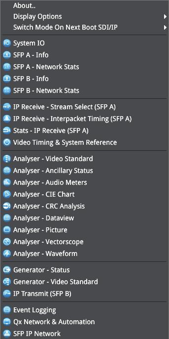
9 Analyser Optical SFP connection The receive connection for IP video is SFP+A. This provides the multi rate IP video analyser connection from HD-SDI to 3G-SDI over IP. If the SMPTE ST 352 packets are known to be incorrect then the user has the option to select Ignore payload identifier packets (ST 352) in the Analyser Configuration window. Generator Optical SFP connection The transmit connection for IP video is SFP+B. This provides the multi rate IP video packet generation from HD-SDI to 3G-SDI over IP. Note: For both SFP+A and SFP+B, use optical SFPs approved by PHABRIX. Use of incompatible SFPs will lead to an error message window appearing on the Qx screen when powered up. LC to LC optical multi-mode duplex fibre cables should be used. Cables of the following specifications are approved by PHABRIX: OM1 (62.5/125), OM2 (50/125), OM3 (50/125), and OM4 (50/125). Powering up the Qx When the Power Button on the Qx is first pressed, the unit fans will cycle for seconds at high speed as the system boots then settle to their normal operating speed. Power Button USB port Menu selection The following menu screen will be displayed after power up: To activate the Instrument Launch Menu left click the PHABRIX symbol on the Instrument Bar. To hide the Instrument Bar left click within its blank area. Bringing the cursor to the bottom of screen re-enables the Instrument Bar. Instrument Launch Menu Page 2


10 Page 3


11 As each instrument is selected, an icon will be placed on the Instrument Bar. The instrument and icon will be assigned a colour. Each icon will glow in the assigned colour to indicate if it is part of a group of instruments related to analyser, generator, or system. This colour Window Frames option can be disabled via Display Options in the Instrument Launch Menu. Instruments automatically group by colour. If one instrument is placed next to another then the border will outline all instruments of a common group in contact with each other to aid group recognition. All instrument windows can be closed simultaneously by right clicking the Instrument Bar and selecting Close All Windows. Each instrument also has a submenu. The submenu is activated by right clicking the mouse in the window, enabling a drop-down configuration menu. Click and drag on the grey bar at the top of the submenu to move it. In addition to window specific commands, the option to Close the instrument is provided in its submenu; as is the option to Dismiss the submenu. Double clicking within a window will cycle through a set of standard instrument sizes. In many cases the size of a window can be further adjusted to suit requirements. Click and drag on an instrument s surface to reposition the instrument. Example of drop-down menu on right mouse click: right click mouse for additional drop-down menus Page 4

12 About Selecting About.. in the Qx Instrument Launch Menu, reveals a window containing information including: Qx software version and build, Serial Number; and license, FPGA, and calibration details. Apply default settings Applying default settings in the Qx Instrument Launch Menu will return the unit s configuration to its factory settings. Switching Mode A Qx IP or Qx 12G with an IP licence can be run in two different boot up modes: SDI and IP. The Qx operation mode is switched via an option in the Instrument Launch Menu : Switch Mode On Next Boot SDI/IP > [Switch To IP, Switch To SDI] Selecting Switch To... the mode the Qx is not currently in, will initiate the switch request. The mode will then switch when the Reboot button that appears is selected. The switch reconfiguration request will take approx. 2 mins 15 secs to complete, during which time the Power Button light at the front of the Qx chassis will flash yellow. The Power Button light will become a fixed yellow colour (instead of white) once a switch mode on next boot up reconfiguration request is complete; indicating that a mode switch request has been successful. Selecting the Reboot button will restart the Qx unit in the mode requested. Powering down the Qx When the Power Button on the Qx is pressed, the unit will shutdown after 10 seconds. To shutdown immediately, press the power button again or click the SHUT DOWN NOW button that will appear in the centre screen shutdown window. To stop shutdown, click the Cancel button in the same window. Page 5
13 Instrument Description The guide that follows is intended as an introduction to the menu selection and the tool-set. The Qx has the advantage of being a generator and an analyser so this tour of the product will be using both toolsets simultaneously. For this guide we will assume that you have connected the unit to itself as shown in the following diagram for SDI or optical SFP use. Connect generator to analyser (SDI) Connect IP transmit to IP receive (SFP) SFP+B SFP+A (IP Transmit) (IP Receive) SDI OUT (Generator) SDI IN (Analyser) Page 6

14 Generation Generator - Video Standard The Generator - Video Standard window is used to select the generator video standard and test pattern. Once selected the new test signal is loaded by pressing the Generate pane. The Audio Generator can also be accessed via the instrument submenu. Note: In this software revision the generator takes approximately 8 seconds to load after which the eye and jitter toolset will be enabled. During this period all other analyser functions are disabled. Right clicking anywhere within the generator window brings up a configuration menu. To simplify selection the generator standards list may be filtered using the following settings: Filter video standard list > Frame Rate > [No filter, 23.98, 24, 25, 29.97, 30, 47.95, 48, 50, 59.94, 60] Filter video standard list > Colour Format > [No filter, YCbCr:422, YCbCrA:4444, RGBA:4444, YCbCr:444, RGB:444, YCbCrA:4224 Filter video standard list > Bit depth > [No filter, 10, 12] Filter video standard list > Active Lines > [No filter, 720, 1080, 2160] Filter video standard list > Sub Image Format > [No filter, Single Image, square division, 2 Sampl...erleave] Filter video standard list > Level > [No filter, A, B] Filter video standard list > Combined SDI rate > [No filter, 1.5G, 3G, 6G, 12G] Filter video standard list > Source image width > [No filter, 1280, 1920, 2048, 3840, 4096] Filter video standard list > Interlace > [No filter, progressive, interlaced, segmented] Filter video standard list > Link Count > [No filter, 1, 2, 4] Filter video standard list > Transfer Curve > [No filter, SDR-TV, PQ] Filters are removed by selecting in menu: Filter video standard list > Clear filters Generator toolset border colour selection is provided for clear identification: Generator tools colour select, [colour] Page 7
 tool shown")

.")


![[SDI only] Pathological Signal](/docs-images/75/72437677/images/15-17.jpg "Insertion is a powerful feature.")
15 Colour selection is via the HSV (Hue, Saturation, Value) tool shown above using two cursors. The left hand colour rectangle allows selection of hue (horizontal) and saturation (vertical). The right hand vertical bar selects luminance. Test Patterns The list of available test patterns for a selected video standard is displayed in the right hand column of the Generator - Video Standard window. These patterns include: 100% Bars 75% Bars Bowtie Box Circle 2 variants Colour Grid Component Ramps Field Lineup Grey 10H Step Grey 10V Step Grey 5H Step Grey 5V Step Grey Steps 2 variants Legal Ramp Luma Ramp 4 variants MultiBurst Pluge 2 variants SMPTE 219 sub super SMPTE 219/ARIB-28 Bars 4 variants of each Tartan Bars Valid Ramps UHD quad Align Pathological signal insertion [SDI only] Pathological Signal Insertion is a powerful feature. In addition to selecting a background test pattern a pathological pattern may be added as an overlay. Page 8
16 Pathological insertion > Insertion > [Enabled, Disabled] Three types of pattern are supported: Pathological insertion > Pattern to overlay > [Eq, PLL, CheckField] The amount of pathological pattern may be configured to enable the user to verify how sensitive the SDI link is to pathological conditions on the interface: Pathological insertion > Pairs to insert > [0 to 16384] This control limits at the selected formats line length. Note: Pathological signals are approved by SMPTE for use with HD and 3G level A standards only. For 3G level B, 6G and 12G-SDI interface formats pathological signals can still be used but are not approved by SMPTE (as of February 2017). It is believed that inserting a full line of pathological signal in these non-approved standards is too stressful a test for the SDI interface. No physical damage will occur but the interface may exhibit reduced operating performance in the form of bit errors. Output offset adjustment [SDI only] A signal can be generated with a fixed offset relative to the system reference. Offsets can be entered in temporal or spatial terms: Output offset adjustment > Offset Type > [Time, Lines And Pixels] Selecting Time reveals a drop-down field where the timing offset can be set in microseconds: Output offset adjustment > Offset Type > Time > Output Time Offset > [0.00, +/- 0.01, etc...] Selecting Lines And Pixels reveals drop-down fields where the offset can be set in these terms: Output offset adjustment > Offset Type > Lines And Pixels > Output Line Offset > [0 to +/- (Total no. of Lines for current standard -1)] Output offset adjustment > Offset Type > Lines And Pixels > Output Pixel Offset >[0 to +/- (Total no. of Pixels per Line for current standard -1)] Generator offset is removed by selecting in menu: Output offset adjustment > Clear offsets Audio Generator 32 channel audio generation is available via the instrument submenu. Both a Quick config mode for fast setup and a Custom config mode for bespoke channel setup are provided. Page 9
![The following audio generator setting are available: Audio Generator > Audio Generator > [Off, Fixed Tone (Quick config), Chromatic Scale (Quick config), Custom] Under the Quick config settings, once](/docs-images/75/72437677/images/17-0.jpg "the audio generation type is selected, Gain, Gain Type, and Pitch can all be configured as required: Audio Generator > Gain Type > [Fixed Levels, Ramp Levels] Pitch > [C 3, C /D 3, D 3, D /E 3, E 3,")
17 The following audio generator setting are available: Audio Generator > Audio Generator > [Off, Fixed Tone (Quick config), Chromatic Scale (Quick config), Custom] Under the Quick config settings, once the audio generation type is selected, Gain, Gain Type, and Pitch can all be configured as required: Audio Generator > Gain Type > [Fixed Levels, Ramp Levels] Pitch > [C 3, C /D 3, D 3, D /E 3, E 3, F 3, F /G 3, G 3, G /A 3, A 3, A /B 3, B 3, C 4, C /D 4, D 4, D /E 4, E 4, F 4, F /G 4, G 4, G /A 4, A 4, A /B 4, B 4, C 5, C /D 5, D 5, D /E 5, E 5, F 5, F /G 5, G 5, G /A 5, A 5, A /B 5, B 5, C 6, C /D 6, D 6, D /E 6, E 6, F 6, F /G 6, G 6, G /A 6, A 6, A /B 6, B 6, C 7] When the Fixed Levels gain type is selected, gain can be adjusted in decibels relative to full scale (dbfs): Audio Generator > Gain > [-144 to 0] Greater flexibility in configuration is provided when the Audio Generator Custom setting is chosen. Custom config allows for the selection of the specific number of audio groups required, and then the setting of frequency in hertz and gain level for each channel individually: Audio Generator > Audio Generator > Custom > Num Groups > [1 to 8] Audio Generator > Audio Generator > Custom > Channel > [0 to 31] The audio channel frequency can entered by keyboard or via the onscreen keypad: Audio Generator > Audio Generator > Custom > Channel > Frequency (Hz) > [0 to 24000] Gain can be adjusted in decibels relative to full scale (dbfs): Audio Generator > Audio Generator > Custom > Channel > Gain > [-144 to 0] To apply the config of the currently selected channel to all channels choose: Apply to all channels Generation Generator - Status The Generator - Status menu shows the generator pattern selected and confirms the SFP output (IP Mode) or SDI OUT A, B, C, D (SDI Mode) presence and Sub Image/Full Image mapping information. It also confirms Video Standard, Test Pattern, and Reference details. This window is status only; there are no user configurations. Page 10
18 System SFP IP Network [IP only] The SFP IP Network window provides an overview of the status of the Qx SFP interfaces used for IP video packet transmission and reception. IP receive (A) and transmit (B) SFP presence, carrier signal presence, interface status, SFP MAC and IP addresses, and packet information are displayed here. Right-clicking in the window reveals a submenu, from where the static IP address, and network/subnet mask of each SFP can be set, by keyboard or onscreen Keypad. Static IP address of SFP: SFP...IP addr and mask > [set IP address of SFP as required] Mask selection is via a drop-down menu. Classless Inter-Domain Routing (CIDR) notation is used; with a default value of /24 (i.e: ): SFP...IP addr and mask > [set mask in drop-down ] Default Gateway: SFP...Gateway IP Addr > [set Gateway IP address as required] IP settings are saved by selecting: Apply SFP...Static IP Parameters Page 11
![Generation IP Transmit (SFP B) [IP only] Page 12 The IP Transmit (SFP B) window is used to transmit the currently generated video standard signal as IP video packets.](/docs-images/75/72437677/images/19-0.jpg "The tool can be used to simulate IP video network packet jitter introduced under a variety of network conditions by providing the ability to adjust the transmission distribution profile.")
19 Generation IP Transmit (SFP B) [IP only] Page 12 The IP Transmit (SFP B) window is used to transmit the currently generated video standard signal as IP video packets. The tool can be used to simulate IP video network packet jitter introduced under a variety of network conditions by providing the ability to adjust the transmission distribution profile. The histogram shows the interval timing distribution of the packets being generated (each second): that is, the number of packets being generated each second, against the deviation of each packet interval from the expected interval time. Transmission status information is also displayed at the bottom of the window, and hovering over this status information reveals a tooltip detailing the Current Transmit Parameters. Right-clicking in the window reveals a submenu. Packet transmission can be switched on and off: Transmit > [On, Off] The type of distribution profile can be selected, and the range of transmission packet intervals can be adjusted. The adjustments are displayed in real-time, in the transmission histogram. Inter Packet Distribution Range > [slider +/ clks] Inter Packet Distribution > [Uniform, Gaussian] Note: Extreme extension of the distribution range increases the statistical packet delay to a point where the high interpacket range (now greater than the nominal video sample rate) will slow the video rate. At such an extreme, a transmission locked to system reference will begin to drift. The submenu also provides the option to plot the number of transmitted packets on the vertical axis, in either linear or logarithmic scale: Y-Axis Scale > [Linear, Log10] Network Settings IP, UDP, and SSRC network settings for packet transmission are set in the submenu, and can be entered by keyboard or via the onscreen keypad. Transmission can be either multicast or unicast. The multicast IP address, or the IP address of the receive device (in the case of unicast) should be set as the destination IP address; as required: Destination IP Address > [set IP address] Note: Unicast transmission to the same Qx unit is not currently available. Attempting such a transmission will produce the following error message: Transmission OFF: Destination MAC address lookup failed.
![UDP parameters: Source UDP Port > [set UDP port number as required] Destination UDP Port > [set UDP port number as required] A Synchronization source identifier (SSRC) can be set for RTP stream](/docs-images/75/72437677/images/20-0.jpg "subscription if required: SSRC > [set ID if required] System SFP (A, B) - Info [IP only] The SFP - Info windows gives at-a-glance physical status information on each Qx SFP module, including")
20 UDP parameters: Source UDP Port > [set UDP port number as required] Destination UDP Port > [set UDP port number as required] A Synchronization source identifier (SSRC) can be set for RTP stream subscription if required: SSRC > [set ID if required] System SFP (A, B) - Info [IP only] The SFP - Info windows gives at-a-glance physical status information on each Qx SFP module, including Identifier, Connector, line code (Encoding), and Vendor details and approval status for use with the Qx. More detailed status information for the SFP such as temperature and voltage are also displayed. Temperature and Power display units can be adjusted via the right-click submenu: Temperature Units > [ C, F] Power Units > [mw, dbm] Page 13
21 System System IO SDI Mode Due to the complexity of the UHDTV standards, PHABRIX has introduced innovative ways of displaying status. This however does involve the information being displayed across several instruments. The System IO window has been designed as a quick view of the signal inputs and outputs attached to the Qx. Active SDI inputs and outputs are indicated by the coloured connectors. An entirely greyed out connector indicate a signal is not present, and the previously coloured ring will be black. The colour of the connectors corresponds to the colour of the instrument borders and instrument icons to aid recognition. The presence of external reference and its standard is also displayed graphically with a coloured connector. If the system is set to lock to the external reference and a stable lock has been achieved, then the inner ring of the EXT REF BNC pictured will be highlighted in grey. BNC image: [Grey (reference connected), Red (error with reference), Black (no reference connected] Note: The EXT REF BNC shows the status of external reference only; which is not necessarily the system reference. System reference is selectable in the Timing and System Reference instrument. Below the graphical connector display is a table showing input and output status, and external reference standard and status. The external reference field displays the following states: EXT REF: [No Signal, Unstable, 525/59.94, 625/50, etc...] If external reference is not currently being used as system reference, its field text will display in yellow. When external reference is the system reference, this table field text will be white. IP Mode Active SFP Receive inputs and Transmit outputs are indicated by the coloured connectors. The colour of the connectors corresponds to the colour of the instrument borders and instrument icons to aid recognition. An entirely greyed out connector indicates that a signal is not present. If an SFP is unseated or not present, this is also displayed graphically with a black void - indicating a missing SFP. SFP presence is shown in a table that also contains external reference standard and status details; as per the SDI version of this UI. Page 14
 / 2022-6 (IP Mode) input signals and highlights the ones used by the video standard being analysed.")
22 Analysis Analyser - Configuration The Analyser - Configuration window controls the video standard being analysed. It lists the payloads on SDI (SDI Mode) / (IP Mode) input signals and highlights the ones used by the video standard being analysed. The Payloads are identified primarily by ST-352 packets, if these are missing the signal stats will be analysed and a best guess payload identifier will be listed. Incorrect ST 352 packets are indicated in red within the Analyser - Configuration window. Ignore Payload Identifier Packets (ST 352) > [Enabled, Disabled] ST-352 packets can be ignored such that a best guess payload identifier is always used. This is done by selecting Enabled in the Ignore Payload Identifier Packets (ST-352) submenu option. Analyser tools colour select > [colour] Colour selection is via a HSV tool providing two cursors. The left hand colour rectangle allows selection of hue (horizontal) and saturation (vertical). The right hand vertical bar selects luminance. Page 15

23 Analysis Stats - SDI In A, B, C, D Stats - SDI In A, B, C and D provide information to verify the format of the signals being analysed. A video signal may be comprised of up to four separate SDI signals hence four separate windows. Example 1 shows the display of data from a single 12G input on input A Example 2 shows the display of data from a quad 3G input hence 4 separate video status windows Page 16
![System IP Receive - Stream Select (SFP A) [IP only] The IP Receive - Stream Select (SFP A) window is where a stream can be selected for reception. An IP video source can be switched here easily.](/docs-images/75/72437677/images/24-0.jpg "Multicast requests can be setup and cancelled via the submenu. The instrument provides a list of all available streams - both multicast and unicast.")
24 System IP Receive - Stream Select (SFP A) [IP only] The IP Receive - Stream Select (SFP A) window is where a stream can be selected for reception. An IP video source can be switched here easily. Multicast requests can be setup and cancelled via the submenu. The instrument provides a list of all available streams - both multicast and unicast. For each stream details including: IP video protocol, IP address, UDP port and SSRC information are all displayed; and video format information for the selected stream, stored at the IP level, is summarized in the Receive Src IP pane. Once selected, a new stream is received by pressing the Receive Src IP pane. The instrument window will indicate which stream the analyser is currently locked to. The submenu accessed by right clicking within the IP Receive - Stream Select (SFP A) window calls up multicast setup and list clearing controls. The displayed list of available streams can be cleared by selecting: Clear input list Multicast Setup Streams can be accessed via an IGMPv3 multicast request. The details of the multicast to be joined must be entered first. The destination IP address of the multicast can entered into the destination IP address fields by keyboard or via the onscreen keypad: Multicast req: Dst IP addr > [ ] Streams transmitting on this multicast will be listed in the instrument window. To join a multicast: Request Multicast To exit a multicast: Leave Multicast Page 17
![System IP Receive - Interpacket Timing (SFP A) [IP only] The instrument provides analysis of IP media packet reception, and gives a real-time indication as to the health of the received signal.](/docs-images/75/72437677/images/25-0.jpg "The histogram displays the distribution of all packet arrival intervals within a given second - the mean, minimum, and maximum packet intervals for this period are also displayed.")
25 System IP Receive - Interpacket Timing (SFP A) [IP only] The instrument provides analysis of IP media packet reception, and gives a real-time indication as to the health of the received signal. The histogram displays the distribution of all packet arrival intervals within a given second - the mean, minimum, and maximum packet intervals for this period are also displayed. Outlier times significantly longer than the expected mean, indicate significant delays in packet propagation. A high occurrence of such long intervals characterises high jitter in a network. Right clicking reveals a submenu with the option to plot the number of received packets on the vertical axis, in either a linear or logarithmic scale: Y-Axis Scale > [Linear, Log10] System Stats - IP Receive (SFP A) [IP only] Stats - IP Receive (SFP A) provides information to verify the format of the signal being analysed. Page 18


26 Analysis Analyser - Picture The picture view shows the generator pattern currently being analysed by the Qx. The picture window may default to full screen - simply right click to change the picture to SMALL or MEDIUM. Right click the mouse to select MOVE to reposition the picture anywhere on the display. Blanking Area By right clicking with the mouse the operator can also enable Show Blanking. This will offset the picture to the right revealing the blanking area. Show Blanking > [Disabled, Enabled] Note: Show Blanking is not available for multiple sub-image video standards as the active picture is separated from the blanking regions during active picture reconstruction. Page 19

27 Picture Cursor With Picture Cursor enabled, a specific line and pixel position can be selected in the picture. This feature is dynamically linked to both the Wavefrom and Dataview instruments; so measurements from the selected picture position can be taken from these tools at the same time. Picture Cursor > [Enabled, Disabled] Picture Cursor > Enabled > Line > [-40 to (Total no. of Lines for current standard -1)] Picture Cursor > Enabled > Pixel > [0 to (Total no. of Pixels for current standard -1)] Note: Keep in mind when using Dataview in conjunction with the Picture and Waveform instruments, that the Dataview includes horizontal blanking, and so uses transport line numbers, not active picture line numbers. HDR Heat-map (False Colour Overlay) [PHQXO-HDR] A false colour overlay can be applied to the picture view, to highlight areas of the image that are of particular luminance. The picture can be displayed in greyscale. If enabled at the same time as False colour highlighting, all image elements outside of the enabled false colour overlay luminance range(s) will be displayed in greyscale mode; leaving the false colour highlight elements to stand out more: Greyscale mode > [Enabled, Disabled] A scale with numeric and graphic display of the luminance range(s) of the overlay in use, is available: False Colour Overlay Scale > [Enabled, Disabled] The required luminance units for the scale can be selected: Luminance Measurement > [Decimal Level, PQ Nits] Different types of false colour overlay may be applied to clearly visualise different image details, and a custom mode is provided to allow the creation of a modified or bespoke overlay: False colour ranges > False Colour Highlighting > [Disabled, PQ HDR, SDR All Bands, SDR Shadow, SDR Skin Tones, SDR Highlights, Out of Range, Custom] The range(s) and colours of a selected false colour overlay can be modified by adjusting the 7 overlay bands. Up to 7 distinct ranges can be simultaneously enabled in a single overlay. If adjusted, the new or modified overlay will be designated as the Custom overlay type. Page 20
![Transfer Curve and Colourimetry Overrides [PHQXO-HDR] There is currently no ratified SMPTE standard for HDR payload ID.](/docs-images/75/72437677/images/28-0.jpg "As a consequence, much HDR content today will contain the SMPTE payload ID for SDR and Rec. 709 colourspace (as standard ).")

28 Transfer Curve and Colourimetry Overrides [PHQXO-HDR] There is currently no ratified SMPTE standard for HDR payload ID. As a consequence, much HDR content today will contain the SMPTE payload ID for SDR and Rec. 709 colourspace (as standard ). Therefore, for accuracy, when analysing most known HDR and WCG content, overrides should be enabled for the appropriate HDR transfer curve, and for WCG colour space: Enable Transfer Curve Override > [Enabled, Disabled] Transfer curve Override > [SDR-TV, PQ] Enable Colourimetry Override > [Enabled, Disabled] Colourimetry Override > [ColRec709, ColUHDTV] All Qx HDR test signals contain the HDR payload ID and therefore do not require overrides for analysis. Analysis Analyser - CIE Chart [PHQXO-HDR] Page 21

29 The CIE 1931 x y chart provides signal chromaticity analysis - complete with WCG and DCI-P3 colour gamut overlays, and Illuminant D65 white point reference. CIE Chart setup is accessed by right clicking within the chart area: Rec. 709 Triangle > [Enabled, Disabled] Rec Triangle > [Enabled, Disabled] P3 Triangle > [Enabled, Disabled] D65 White Point > [Enabled, Disabled] Single Line Mode > [Enabled, Disabled] Zoom > [slider ] x Position > [slider, left to right] y Position > [slider, down to up] Brightness > [slider 1..31] Gamma > [slider ] Persistence [slider ] Zoom can also be performed by hovering the mouse crosshairs over the chart and scrolling the mouse wheel. Panning in the x and y axes can also be performed by hovering the mouse crosshairs over the axis in question and scrolling the mouse wheel. Analysis Analyser - Waveform The Waveforn instrument provides various analysis settings including Single Line Mode and Picture Cursor control. When Picture Cursor is enabled, the cursor is dynamically linked to the cursor in the Picture instrument, and to Dataview navigation. Clicking the cursor in a new position in the Waveform window updates the pixel and active picture line position selected in the Picture instrument, and the pixel and transport line position selected in Dataview. Waveform setup is accessed by right clicking within the waveform area: Parade Mode > [YCbCr, Y, Cb, Cr, RGB, GBR, YRGB, YGBR, Red, Green, Blue] V Scale > [% IRE, Hex Value, Decimal Value, Millivolts, PQ Nits] H Scale > [Pixels, % Line] Page 22
![Filter > [Flat, Low Pass, Raw] Single Line Mode > [Enabled, Disabled] Single Line Mode > Enabled > Line Number > [-40 to (Total no.](/docs-images/75/72437677/images/30-0.jpg "of Lines for current standard -1)] Picture Cursor > [Enabled, Disabled] Picture Cursor > Enabled > Pixel Number > [0 to (Total no.")
30 Filter > [Flat, Low Pass, Raw] Single Line Mode > [Enabled, Disabled] Single Line Mode > Enabled > Line Number > [-40 to (Total no. of Lines for current standard -1)] Picture Cursor > [Enabled, Disabled] Picture Cursor > Enabled > Pixel Number > [0 to (Total no. of Pixels for current standard -1)] H Magnification > [x1, x2, x4] H Position > [slider] V Magnification > [x1, x2, x4] V Position > [slider] Brightness > [slider 1..31] Gamma > [slider ] Persistence [slider ] Monochrome mode [Enabled, Disabled] Analysis Analyser - Vectorscope Vectorscope setup is accessed by right clicking within the vectorscope area: Targets > [Off, 75%, 100%] I/Q Axes > [Off, I Only, Q Only, Both] Filter > [Flat, Low Pass, Raw] Centre > [Origin, Red, Green, Blue, Magenta, Cyan, Yellow] Single Line Mode > [Enabled, Disabled] Zoom > [slider ] Brightness > [slider 1..31] Gamma > [slider ] Persistence [slider ] Page 23
![Analysis Eye - SDI in A [PHQX-01E only] One of the unique features of the Qx is the PHYSICAL layer analysis tool-set.](/docs-images/75/72437677/images/31-0.jpg "The PHABRIX Qx contains fundamental technology developed and patented by PHABRIX which makes it unique where physical layer compliance measurements are required up to 12 Gbps.")
 technology the Qx is in a league of its own.")
31 Analysis Eye - SDI in A [PHQX-01E only] One of the unique features of the Qx is the PHYSICAL layer analysis tool-set. The PHABRIX Qx contains fundamental technology developed and patented by PHABRIX which makes it unique where physical layer compliance measurements are required up to 12 Gbps. The Qx employs an analogue front end providing in excess of 30 GHz bandwidth (5th harmonic of the 6GHz fundamental for 12G-SDI). Featuring PHABRIX RTE TM (Real Time Eye) technology the Qx is in a league of its own. More akin to expensive high end oscilloscopes, the Qx provides broadcast engineers with a reliable, instantaneous physical layer display with automatic measurements to SMPTE standards. The PHABRIX Qx enables measurement of both overshoot and undershoot along with amplitude, rise time, fall time and delta - compulsory when testing against SMPTE standards and a key differentiator when comparing Qx technology. Accurate measurements are obtained with seconds of connecting an SDI signal making for very fast system testing solution. Out of specification measurements are indicated in red. Example 1: 12G-SDI Eye pattern display with 100 khz jitter filter Example 2: 3G-SDI Eye pattern display with 100 khz jitter filter Note: SDI In A has a red nut to indicate it is the SDI BNC that has the eye and jitter circuitry behind it Page 24
 Selections include: Eyes > [1, 2, 3.")
32 The Physical Layer tool-set has several drop-down menus selected by a right click of the mouse. (A table showing the SMPTE tolerances for each standard is available at the end of this manual.) Selections include: Eyes > [1, 2, ] Colour > [Green, Heat, Red, Ferrara, Green-red, Blacklight] Eye and jitter filter > [10Hz, 100Hz, 1kHz, 10kHz, 100kHz] Infinite mode >[Enabled, Disabled] The display also provides: Timing jitter thermometer colour coded according to analysed SDI standard Alignment jitter thermometer colour coded according to analysed SDI standard On screen indication of 20% and 80% levels for rise and fall time measurement On screen indication of +10% and -10% levels for overshoot and undershoot analysis Positive and negative amplitude values providing DC offset information Horizontal histogram of eye crossing point (0mV threshold) Vertical histogram providing indication of energy distribution over all samples Page 25
![Analysis Jitter - SDI In A [PHQX-01E only] The jitter tool-set is available on the SDI In A BNC (the one with the red nut) The jitter instrument shows automated measurements to SMPTE standards.](/docs-images/75/72437677/images/33-1.jpg "Readings for each of the filters are shown displayed as an overlay on the right hand side of the instrument. Any red text displayed indicates an out of specification reading.")
33 Analysis Jitter - SDI In A [PHQX-01E only] The jitter tool-set is available on the SDI In A BNC (the one with the red nut) The jitter instrument shows automated measurements to SMPTE standards. Readings for each of the filters are shown displayed as an overlay on the right hand side of the instrument. Any red text displayed indicates an out of specification reading. As with the Eye instrument, further drop-down menus are available using the right click on the mouse control: Scale > [sliding scale: Y graticule adjustment from +/- 0.2 UI to +/-8UI] Trigger > [None, Single Line, Two Lines, Single Field, Two Fields, Frame] Eye and jitter filter > [10Hz, 100Hz, 1kHz, 10kHz, 100kHz] Infinite Mode > [Enabled, Disabled] Jitter Colour > Waveform colour selection Colour selection is via a HSV tool providing two cursors. The left hand colour rectangle allows selection of hue (horizontal) and saturation (vertical). The right hand vertical bar selects luminance. Trigger modes are useful for correlating jitter content to line and frame rate frequencies Page 26


34 Analysis Analyser - Dataview This instrument presents the raw data present in the signal be it HD-SDI, 3G-SDI, 6G-SDI or 12G-SDI. The data can be observed in hexadecimal, decimal or binary formats and the data is navigated by pixel and line selection. The instrument displays the entire video frame complete with active video, TRS words and blanking information. By right clicking using the mouse on this instrument, the following drop-down menus are presented: Sample > [slider 0 to max_pix_count] Line > [slider 0..max_line_count] Navigate > [calls up navigation pane - see below] Base > [hex, decimal, binary] Field > [Field 1, Field 2] (standard dependant) Sub-Image > [Sub Image 1, Sub Image 2, Sub Image 3, Sub Image 4] (standard dependant] Data is presented with a colour coding for both text and background: Foreground colour indicates video sample type: Y (white), Cb (blue), Cr (red) Background colour indicates data type: TRS words (blue), Blanking (black), Active picture (green) Changing the window size changes the amount of data displayed. A navigation keypad activated by selecting Navigate on the top bar of the instrument allows the user to quickly navigate the dataview window. Page 27

35 Analysis Video Timing and System Reference The upper part of the instrument view is devoted to SDI A vs System Reference timing comparison ( Decapsulated vs Reference in IP Mode); and system reference is set in the instrument submenu. The lower part displays SDI Co-timing information for elements of a quad or dual link signal. System Reference Lock The submenu accessed by right clicking within the Video Timing and System Reference window calls up system reference locking controls; defining the reference that the Qx system and any signal it generates will be locked to: System Reference > [Free Run, External Reference, SDI (SDI Mode only)] Default To Freerun > [Enabled, Disabled] System reference status information is displayed in the upper right hand corner of the instrument, and any reference health state error will be displayed in red. SDI A vs System Reference / Decapsulated vs System Reference This section of the instrument displays the timing difference between the SDI A input signal (or Decapsulated input - IP Mode) and the system reference the Qx is locked to. Both graphic and numeric (spatial and temporal) values are presented by the instrument for this measurement. A relative timing bar tool dynamically measures the timing of the input (white triangle) against the system reference (centrally fixed black vertical crosshair). The tool can be adjusted to display readings at frame scale, or zoom in all the way to a fraction of a line: Reference Timing Meter Range > [+/- 0.1 line, +/- 0.5 line, +/- 0.5 frame] Input Measurement Offset In addition to measurement of the input against absolute system reference, a system reference offset can also be applied in the tool to measure against. The offset position is indicated on the relative timing bar tool with a black triangle. Offsets can be entered in temporal or spatial terms: Input Measurement Offset Type > [Time, Lines And Pixels] Selecting Time reveals a drop-down field where the timing offset can be set in microseconds: Input Measurement Offset Type > Time > Input Measurement Time Offset > [0.00, +/- 0.01, etc...] Page 28
] Input Measurement Offset Type > Lines And Pixels >Input Measurement Pixel Offset > [0 to +/- (Total no.")
36 Selecting Lines And Pixels reveals drop-down fields where the offset can be set in these terms: Input Measurement Offset Type > Lines And Pixels > Input Measurement Line Offset > [0 to +/- (Total no. of Lines for current standard -1)] Input Measurement Offset Type > Lines And Pixels >Input Measurement Pixel Offset > [0 to +/- (Total no. of Pixels per Line for current standard -1)] The input measurement offset can be set to the same position as the current SDI In A (or Decapsulated - IP Mode) signal: Set Input Measurement Offset to current The input measurement offset is removed by selecting in menu: Clear Input Measurement Offset SDI Co-Timing [SDI only] Many of the standards associated with UHDTV are a combination of signals to form the image plane. Relative timing tools indicate that the quad or dual elements creating the single picture are correctly aligned and compared with reference. Both graphic and numeric values are presented by the instrument for this critical measurement. Any red text displayed indicates an out of specification measurement. Note: The Timing instrument in this software release is locked to Input A. Analysis Analyser - Ancillary Status The Qx has a sophisticated display to analyse ancillary data in the signal. UHDTV has a new set of rules for carrying this data. The clear graphical representation of this is required to establish compliance. Colour coded signal conditions - present, lost, and error are all available. Additional data is displayed as the instrument is resized. White - Indicates ANC packets present and correct Red - Indicates ANC packets present but in error Yellow - indicates ANC packets present and correct but there has been a previous error Status is reset by selecting in menu: Reset Page 29

37 Analysis Analyser - Audio Meters The Analyser - Audio Meters instrument displays 16 x audio meters along with peak level indication and audio pair phase indication. In addition dbfs values are indicated at the base of each meter. Dolby E, D and D+ streams are detected by the system with Dolby stream indication in blue. The HDMI instrument output carries a stereo pair of audio, the same signal is made available on the 26- way D-type at the rear of the Qx chassis. Stereo pair monitoring selection is provided by selecting the speaker icon above each set of audio meters. Mono channel selection is provided by selecting the appropriate solo bus located between the audio meters and the speaker icons. Menu options provided: Input Select > [Image/Sub-Image 1 Group 1-4, Image/Sub Image 1 Group 5-8, Sub-Image 2 Group 1-4, Sub-Image 2 Group 5-8, Sub-Image 3 Group 1-4, Sub-Image 3 Group 5-8, Sub-Image 4 Group 1-4, Sub-Image 4 Group 5-8] Ballistics > [PPM Type I, PPM Type II, Vu, VuFr] PPM Scale Type > [dbfs, dbu -18dBFS, dbu-20dbfs, BBC, DIN45406, NordicN9] Hat Hold Time > [ , infinity] Monitor Buttons > [Enabled, Disabled] Solo Buttons > [Enabled, Disabled] Up to two audio meter instrument windows can be enabled providing 32 simultaneous channels of audio metering. Each window is assignable to monitor groups 1 to 4 (defined in SMPTE ST 299-1) or groups 5 to 8 (defined in SMPTE ST 299-2) in any of up to 4 potential sub-image ANC areas as defined in SMPTE ST Each audio window is scalable from 1/32 to 1/4 of screen area. Page 30

38 Analysis Analyser - CRC Analysis The Analyser - CRC Analysis window checks for CRC errors in the signal. Dependant on the input required for the standard under test, i.e. 4 inputs or single, the Sub Image columns will show any errors in each of the inputs attached. The Last error timer event shows in seconds the last CRC error event in each input. In addition, a separate timer indicates the time since error checking began. The instrument also analyses the CRC of the overall active picture to detect changes. Reset errors and running time System SFP (A, B) - Network Stats [IP Only] The Network Stats window displays transmission and reception traffic information, detailing the type and number of packets sent and received by an SFP. CRC errors are identified and packet sequence errors reported. Double-clicking the window expands it, to reveal additional packet information. Page 31

39 System Event Logging Logging is provided on the Qx, and logs can be viewed in Event Logging. The Qx allocates 500 lines for logging detail before overwriting this data. It will also recall the log data last captured if the unit is started from cold. The setting for logging data will need to be re-entered from a cold start using the right click selection. Logs can also be accessed and saved via the REST API. SDI Mode By right clicking the mouse on this instrument the following drop-down menus are presented: Record Jitter Timing Logs > [Enabled, Disabled] Record Jitter Alignment Logs > [Enabled, Disabled] Record SDI Input Standard Logs > [Enabled, Disabled] Record SDI Input Rate Logs > [Enabled, Disabled] Record REST API Request Logs > [Enabled, Disabled] Record Reference Locking Logs > [Enabled, Disabled] Clear logs IP Mode By right clicking the mouse on this instrument the following drop-down menus are presented: Record Reference Locking Logs > [Enabled, Disabled] Record IP Tx Logs > [Enabled, Disabled] Record IP Rx Logs > [Enabled, Disabled] Record IP Interfaces Logs > [Enabled, Disabled] Record SFP Logs > [Enabled, Disabled] Clear logs Event logging will be developed further in future software releases. Page 32
40 System Qx Network The Qx can be controlled remotely via REST API, which can be used for automated testing. The IP address of the Qx can be dynamically assigned on a DHCP enabled network, or a static IP address can be set. From the Qx Network window a remote connection can be established by enabling REST API in the submenu: REST API > [Disabled, Enabled] The Network Status window contains all the information on the Qx that is needed in order to send it a REST request. IP Address (or mdns Hostname if your client s host supports it) should be used as the recipient of the request, and REST API Port is the port that requests will need to be directed towards. The REST API supports two HTTP methods: GET and PUT. GET requests can be used to retrieve Qx information and navigate the submenus. PUT requests can be used to modify and control Qx behaviour and actions. A web browser can be used to retrieve Information from the Qx with GET requests. Any HTTP/1.1 compliant application can be used to control the Qx with both GET and PUT requests. PUT and GET requests can be scripted for automated testing. REST API Requests For the following REST API request examples, an example IP address ( ) and default REST API Port (8080) are used. The base resource to aim requests at is /api. The base URL for requests (GET) will be in the format: or REST API requests can be used to: Report the current analysed standard (GET): Report the currently generated standard (GET): status Navigate through list of available generator standards (GET): generator/standards. Select from tree and GET again to drill down to appropriate colour format, bit depth, level, SDR or HDR format, and test pattern. Generate a standard (PUT): standards/1920x1080p60/ycbcr%3a422%3a10/3g_a/100%25%20bars. A pathological overlay, its type and number of pairs can be added by including a raw payload of, for example, { action : start, pathological :{ type : CheckField, pairs :100}} Page 33

: http://192.168.0.142:8080/api/v1/jitter/status Retrieve the event logs (GET): http://192.168.0.142:8080/api/v1/eventlog/logs Report current CRC analysis status (GET): http://192.")
41 Report the currently generated audio standard (GET): generator/audio Audio generation (PUT): Including a raw payload for Quick config, of the structure, for example, { mode : Fixed Tone, quickconfig :{ gaintype : Fixed Levels, gain : -10, pitch : E 3 }}. For Custom config raw payload structure, refer to the GET request output structure. View instantaneous Eye readings (GET): View instantaneous Jitter readings (GET): Retrieve the event logs (GET): Report current CRC analysis status (GET): crcsummary Manage the event logs (PUT): with a raw payload of { action : enable } in this example, to enable REST API event logging. System Time and NTP By right clicking the time displayed on the right hand side of the menu bar, a separate window will be displayed. Use the slider control to select the required time zone: NTP can be turned off which will then provide manual control of time setting. To return to NTP use the mouse to select the Automatic feature. Time Zone > [select zone] Set Time & Date > Automatic [check box] Set Time & Date > Update Now [press to update] NTP Server: > [eg. pool.ntp.org] Page 34
42 System Driver Calibration [PHQX-01E] Note: All PHABRIX units are calibrated and verified prior to dispatch. Over time however, the SDI generator outputs of the Qx may require recalibration. On units with PHABRIX RTE (Real Time Eye) capability (PHQX-01E only), the SDI generator outputs of the Qx can each be calibrated using the SDI A Input of the Qx. Note: Recalibration relies upon the calibration status of the Eye/Jitter analyser. If in doubt consider returning the unit to PHABRIX for calibration. Warning: Before attempting Qx calibration, be sure to that you are using a 12G cable of the specification described below. If in doubt, do not attempt to perform calibration on your unit. SDI Output Calibration Steps Calibration can be performed by first, connecting a 1metre long cable between SDI A Input and the SDI Output to be calibrated. A 12G-SDI grade or compatible cable with 12G-SDI BNCs must be used. Suitable cable types include: Canare L-5.5CUHD, and Belden 1694A. Next, from the Instrument Launch Menu, selecting System Settings > Driver Calibration opens a calibration window. A drop-down menu allows the selection of the output to be calibrated. For SDI Output A, select Driver A, etc. Select Start to begin calibration. The calibration of an output should take 2-5 minutes. Once SDI Output A is calibrated, connect the output side of the cable to SDI Output B and repeat the process outlined above, until all Qx SDI Outputs have been calibrated. It may take approximately 20 minutes to calibrate all four outputs. Page 35
43 Specifications Power Connector Voltage 4-pin XLR, Male 10-18V, 12V DC nominal DC Power adapter provided Overvolatge, undervoltage and reverse voltage protection External Locking Reference Label Input Signal Connector Input Impedance Input Return Loss REF Tri-level or Bi-Level (black burst) syncs 50/59.94/60Hz 2x BNC > 10kΩ Maximum Input voltage +/- 2V Specification >40dB to 6MHz (typical) Tri-level syncs (SMPTE 274M and SMPTE 296M) 600 mv pk-pk PAL Black Burst (ITU 624-4/SMPTE 318) 1V pk-pk, Composite NTSC (SMPTE 170M) 1V pk-pk SDI Instrument Output Label SDI OUT Connector BNC Output Impedance 75Ω Output Level 800mV p-p +/-10% Purpose 3Gbps SDI instrument output HDMI Instrument Output Label Connector HDMI Type A Video Format 1920 x 1080 RGB 4:4:4 Audio Format Purpose 4 x PCM stereo audio at 48 KHz Monitor output that allows up to 16 individual instrument panels (or windows) to be displayed. USB USB USB 2 USB Connector Quantity Purpose Type A 3 (1 x front mounted, 2 x rear mounted) Keyboard and mouse control of the HDMI monitor output of instrument and software installation. Page 36
44 Networking Ethernet Ethernet Connector IEEE /100/1000Mb/s (10/100/1000 base-t) RJ-45 Rear panel D26 Label: Connector: Purpose: I/O Expansion 26-way D-type 8x GPI I/O, 4x AES I/O, LTC input, stereo analogue audio out Pin out: Pin Number Pin Name Description 1 AES_IO0 Bidirectional AES I/O - 75Ohm unbalanced 2 AES_IO1 Bidirectional AES I/O - 75Ohm unbalanced 3 AES_IO2 Bidirectional AES I/O - 75Ohm unbalanced 4 AES_IO3 Bidirectional AES I/O - 75Ohm unbalanced 5 LTC_RX_P LTC Receive (RX) P (RS-422 compatible) 6 LTC_RX_N LTC Receive (RX) N (RS-422 compatible) 7 AUDIO_R Audio Line Out - right 8 AUDIO_L Audio Line Out - left 9 5V0_GPIO 5V current limited GPIO supply (500mA) 10, 11, 12, 13, GND 0V 14, 15, 16, 17, GPIO-0 Open drain,10k pull-up to +5V 20 GPIO-1 Open drain,10k pull-up to +5V 21 GPIO-2 Open drain,10k pull-up to +5V 22 GPIO-3 Open drain,10k pull-up to +5V 23 GPIO-4 Open drain,10k pull-up to +5V 24 GPIO-5 Open drain,10k pull-up to +5V 25 GPIO-6 Open drain,10k pull-up to +5V 26 GPIO-7 Open drain,10k pull-up to +5V AES I/O Connector 26-way D-type Pins 1 (AES I/O 1), 2 (AES I/O 2), 3 (AES I/O 3), 4 (AES I/O 4) Input Impedance 75 Ω terminated Maximum Input Voltage +/- 2V Input Sample Rate Input Bit Depth Output Sample Rate Output Bit Depth Specification Purpose 48kHz synchronous audio 20bit or 24bit 48kHz synchronous to system reference 24bit Conforming to AES and SMPTE-276M Not currently supported in software Page 37
45 Longitudinal Timecode (LTC) Connector Pins Format Purpose 26-way D-type 5 (RX - P), 6 (RX-N) RS-422 Compatible Not currently supported in software Analogue Audio Output Connector Pins Type Level Purpose 26-way D-type 7 (Audio Line Out - Right), 8 (Audio Line Out - Left) Stereo Pair (1V peak-to-peak analogue audio, full scale 0dBFS) Audio Monitoring output GPIO Connector 26-way D-type Pins 19 (GPIO - 0), 20 (GPIO - 1), 21 (GPIO - 2), 22 (GPIO - 3), 23 (GPIO - 4), 24 (GPIO - 5), 25 (GPIO - 6), 26 (GPIO - 7) Format Power Purpose open drain with 10kΩ pull-up to +5 Volts 5 Volt (pin 9), current-limted GPIO supply for open drain input/outputs. 0 Volt/ signal ground (pins 10 to 18) Not currently supported in software Page 38


46 On-going Development PHABRIX is committed to developing the tool-sets on the Qx to meet the very high expectations of its customers. There will be frequent upgrades which will include improvements to existing instruments and the addition of new ones. Please do not hesitate to contact PHABRIX at any time to discuss your requirements for the product or to discuss the current product time-line. SMPTE UHDTV: SDI PHYSICAL LAYER Coding Scrambled NRZI Scrambled NRZI Scrambled NRZI Scrambled NRZI Amplitude 800 mv +/- 10% 800 mv +/- 10% 800 mv +/- 10% 800 mv +/- 10% DC Offset 0.0 V +/- 0.5 V 0.0 V +/- 0.5 V 0.0 V +/- 0.5 V 0.0 V +/- 0.5 V Rise/Fall time: < 270 ps < 135 ps < 80 ps < 45 ps Rise/Fall time difference: < 100 ps < 50 ps < 35 ps < 18 ps Over/Under-shoot: <10% ofthe amplitude <10% ofthe amplitude <10% ofthe amplitude <10% ofthe amplitude Timing Jitter Alignment Jitter < 1UI (10 Hz to MHz) < 0.2 UI (100 khz to MHz) < 2 UI (10 Hz to 297 MHz) < 0.3 UI (100 khz to 297 MHz) < 4 UI (10 Hz to 594 MHz) < 0.3 UI (100 khz to 594 MHz) < 8UI (10 Hz to 1188 MHz) < 0.3 UI (100 khz to 1188 MHz) Qx 75 Ohm Coaxial cable length 200 m 200 m 100 m 70 m (Belden 1694A) Qx 75 Ohm Coaxial cable length (Canare L-5.5CUHD) Automatic measurement provided by Qx 100 m (colour bars) The complexity of both analysing and generating signals for UHDTV is exemplified above. The data bandwidth testing from HD through to UHDTV at 12Gbps, standard on the Qx, is immense and the parameters set by SMPTE require that the instruments measure these critical values for compliance. Page 39
PHABRIX. PHABRIX Qx Operation Manual. broadcast excellence. Software Release Manual Revision 4 PHQX-01, PHQX-01E. Copyright PHABRIX Ltd 2017
 PHABRIX broadcast excellence Software Release 1.0.3 Manual Revision 4 G QX PHQX-01, PHQX-01E Copyright PHABRIX Ltd 2017 About this Manual Notice The information in this document has been produced by PHABRIX
Qx IP I Qx 12G USER MANUAL. Software Release 2.4. Manual Revision 9d
 Qx IP I Qx 12G USER MANUAL Software Release 2.4 Manual Revision 9d Page II About this Manual Notice The information in this document has been produced by PHABRIX Ltd with care and is believed to be accurate.
Qx IP Qx 12G IP, 4K/UHD + HDR generation, analysis & monitoring
 Qx IP Qx 12G IP, 4K/UHD + HDR generation, analysis & monitoring Qx IP Qx 12G IP, 4K/UHD + HDR generation, analysis & monitoring The Qx range brings together all the advanced, hybrid IP/SDI test & measurement
Qx Series IP/12G-SDI, 4K/UHD, HDR/WCG GENERATION, ANALYSIS & MONITORING
 Qx Series IP/12G-SDI, 4K/UHD, HDR/WCG GENERATION, ANALYSIS & MONITORING Qx Series IP/12G-SDI, 4K/UHD, HDR/WCG Generation, Analysis & Monitoring The Qx range brings together all the advanced Test & Measurement
Ultra 4K Tool Box. Version Release Note
 Ultra 4K Tool Box Version 2.1.43.0 Release Note This document summarises the enhancements introduced in Version 2.1 of the software for the Omnitek Ultra 4K Tool Box and related products. It also details
IP, 4K/UHD & HDR test & measurement challenges explained. Phillip Adams, Managing Director
 IP, 4K/UHD & HDR test & measurement challenges explained Phillip Adams, Managing Director So what are the big challenges facing the industry? HD UHD Higher bandwidths for immersive 4K/UHD HDR/WCG gaining
AX20. Atlas 19.5" 3G-SDI/HDMI Field and Studio Monitor with 3D LUTs & Scopes. Quick Start Guide. What s Included CHECKED BY
 AX20 Quick Start Guide Atlas 19.5" 3G-SDI/HDMI Field and Studio Monitor with 3D LUTs & Scopes What s Included 1 x Atlas 19.5" Monitor 1 x AC Adapter 1 x Sunhood CHECKED BY AX20 FRONT 1920 x 1080 19.5 inch
Ultra TQ V3.4 Update 4KTQ Ultra TQ Update 1
 Ultra TQ Ultra TQ Update 1 About this Document Notice This documentation contains proprietary information of Omnitek. No part of this documentation may be reproduced, stored in a retrieval system or transmitted
Qx Series IP/12G-SDI, 4K/UHD, HDR/WCG GENERATION, ANALYSIS & MONITORING
 Test Equipment Depot - 8.517.8431-99 Washington Street Melrose, MA 2176 - TestEquipmentDepot.com Qx Series IP/12G-SDI, 4K/UHD, HDR/WCG GENERATION, ANALYSIS & MONITORING Qx Series IP/12G-SDI, 4K/UHD, HDR/WCG
CPLUS-V2PE 4K UHD+ HDMI to Dual HDMI Scaler with Audio De-Embedding & Test Patterns
 CPLUS-V2PE 4K UHD+ HDMI to Dual HDMI Scaler with Audio De-Embedding & Test Patterns Operation Manual DISCLAIMERS The information in this manual has been carefully checked and is believed to be accurate.
FS3. Quick Start Guide. Overview. FS3 Control
 FS3 Quick Start Guide Overview The new FS3 combines AJA's industry-proven frame synchronization with high-quality 4K up-conversion technology to seamlessly integrate SD and HD signals into 4K workflows.
Test Equipment Depot Washington Street Melrose, MA TestEquipmentDepot.com
 Test Equipment Depot - 800.517.8431-99 Washington Street Melrose, MA 02176 - TestEquipmentDepot.com Read this first Product documentation Covered products The following Tektronix products are covered by
SX7. Saga 7" Super Bright HDMI/3G-SDI Field Monitor with 3D-LUTs. Quick Start Guide. What s Included CHECKED BY
 SX7 Quick Start Guide Saga 7" Super Bright HDMI/3G-SDI Field Monitor with 3D-LUTs What s Included 1 x Saga X7 Monitor 1 x V-Mount Plate (Attached) 1 x Mini-XLR to P-TAP Cable 1 x Dual Sony L Battery Adapter
V pro8 QUICK START GUIDE
 QUICK START GUIDE Welcome to your V pro8 FIRST STEPS POWERING ON CONNECTING YOUR COMPUTER Thank you for buying the Lawo V pro8, a true high-quality product developed and manufactured in Rastatt, Germany.
ModelV-LCD70-AFHD. Operating Instructions
 ModelV-LCD70-AFHD Operating Instructions 1 2 This page intentionally left blank Table of Contents Top and Front Panel Features...6 Rear Panel Features...7 Compatible Input Formats...8 MAIN MENU AND NAVIGATION...9
SM02. High Definition Video Encoder and Pattern Generator. User Manual
 SM02 High Definition Video Encoder and Pattern Generator User Manual Revision 0.2 20 th May 2016 1 Contents Contents... 2 Tables... 2 Figures... 3 1. Introduction... 4 2. acvi Overview... 6 3. Connecting
DRAFT RELEASE FOR BETA EVALUATION ONLY
 IPM-16 In-Picture Audio Metering User Manual DRAFT RELEASE FOR BETA EVALUATION ONLY Ver 0.2 April 2013 1 Contents Introduction...3 In Picture Audio Meter Displays...4 Installation...7 External Audio Board
SingMai Electronics SM06. Advanced Composite Video Interface: HD-SDI to acvi converter module. User Manual. Revision 0.
 SM06 Advanced Composite Video Interface: HD-SDI to acvi converter module User Manual Revision 0.4 1 st May 2017 Page 1 of 26 Revision History Date Revisions Version 17-07-2016 First Draft. 0.1 28-08-2016
CP-255ID Multi-Format to DVI Scaler
 CP-255ID Multi-Format to DVI Scaler Operation Manual DISCLAIMERS The information in this manual has been carefully checked and is believed to be accurate. Cypress Technology assumes no responsibility
SCHD24K 4K UHD + HDMI to HDMI Scaler
 SCHD24K 4K UHD + HDMI to HDMI Scaler Operation Manual DISCLAIMERS The information in this manual has been carefully checked and is believed to be accurate. Ampronix assumes no responsibility for any infringements
OmniTek
 OmniTek www.omnitek.tv Advanced Measurement Technology OTR 1001 Advanced Waveform Rasterizer, Signal Generator, Stereo 3D Monitor, Picture Quality Analyzer 3Gb/s Dual-Link HD SD 1RU chassis Introducing
LV 58SER06 3G-SDI INPUT INSTRUCTION MANUAL
 LV 58SER06 3G-SDI INPUT INSTRUCTION MANUAL Contents 1. INTRODUCTION... 1 1.1 Scope of Warranty... 1 1.2 Operating Precautions... 1 1.2.1 Maximum Allowable Input Voltage... 1 1.2.2 Shorting and Applying
OPERATING GUIDE. HIGHlite 660 series. High Brightness Digital Video Projector 16:9 widescreen display. Rev A June A
 OPERATING GUIDE HIGHlite 660 series High Brightness Digital Video Projector 16:9 widescreen display 111-9714A Digital Projection HIGHlite 660 series CONTENTS Operating Guide CONTENTS About this Guide...
Network Video Analyzer. Signal Analysis Software Version 6
 Network Video Analyzer Signal Analysis Software Version 6 Table of Contents About Network Video Analyzer...3 Reference...5 Main Interface Overview...5 IP Setup Window...12 Settings Window...14 Data View...20
EEG A1452 SCTE-104 Inserter Frame Card
 EEG A1452 SCTE-104 Inserter Frame Card Product Manual EEG Enterprises, Inc. 586 Main Street Farmingdale, New York 11735 TEL: (516) 293-7472 FAX: (516) 293-7417 Copyright EEG Enterprises, Inc. 2017 All
FS4 Quick Start Guide
 FS4 Quick Start Guide Overview FS4 is AJA s flagship frame synchronizer and converter, offering incredible versatility and connectivity in a sleek and compact 1RU frame for all your 4K/ UltraHD/2K/HD/SD
PHABRIX SxE. PHABRIX SxD. PHABRIX Sx. Generator/Analyser/ Monitor/EYE and JITTER +AES. Generator/Analyser/ Monitor/Dual Link. Generator/Analyser/
 Leader Electronics is proud to represent the Phabrix product line in Asia. This new solution provider for Leader Electronics, Phabrix, introduced their new Phabrix SXE along with several options and upgrades
C8491 C8000 1/17. digital audio modular processing system. 3G/HD/SD-SDI DSP 4/8/16 audio channels. features. block diagram
 features 4 / 8 / 16 channel LevelMagic2 SDI-DSP with level or loudness (ITU-BS.1770-1/ ITU-BS.1770-2, EBU R128) control 16 channel 3G/HD/SD-SDI de-embedder 16 in 16 de-embedder matrix 16 channel 3G/HD/SD-SDI
FS1-X. Quick Start Guide. Overview. Frame Rate Conversion Option. Two Video Processors. Two Operating Modes
 FS1-X Quick Start Guide Overview Matching up and synchronizing disparate video and audio formats is a critical part of any broadcast, mobile or post-production environment. Within its compact 1RU chassis,
SMPTE STANDARD Gb/s Signal/Data Serial Interface. Proposed SMPTE Standard for Television SMPTE 424M Date: < > TP Rev 0
 Proposed SMPTE Standard for Television Date: TP Rev 0 SMPTE 424M-2005 SMPTE Technology Committee N 26 on File Management and Networking Technology SMPTE STANDARD- --- 3 Gb/s Signal/Data Serial
Marshall Electronics. Operating Instructions. Warranty. Model No. QVW Quad-Viewer Monitor with 4K Format Support
 Warranty Marshall Electronics warranties to the first consumer that this QVW-2710 LCD monitor will, under normal use, be free from defects in workmanship and materials, when received in its original container,
4kScope Signal Analysis Software Version 6
 4kScope Signal Analysis Software Version 6 Table of Contents About 4kScope...4 Reference...5 Main Interface Overview...5 Settings Window...7 Data View...13 Picture...14 Vectorscope...16 Vectorscope Setup...16
Model 5240 Digital to Analog Key Converter Data Pack
 Model 5240 Digital to Analog Key Converter Data Pack E NSEMBLE D E S I G N S Revision 2.1 SW v2.0 This data pack provides detailed installation, configuration and operation information for the 5240 Digital
DH5e-V2. Delta 5 On-Camera 4K HDMI Monitor with 3D LUTs. Quick Start Guide. What s Included
 DH5e-V2 Quick Start Guide Delta 5 On-Camera 4K Monitor with 3D LUTs What s Included 1 x DH5e-V2 Monitor 1 x L Series Battery Plate 1 x AC Adapter 1 x Screen Cleaning Wipe 1 x Screen Protection Film 1 x
OPERATION MANUAL. USF-1013DEMUX Digital Audio Demultiplexer. 2 nd Edition. Software Version Higher
 OPERATION MANUAL USF-1013DEMUX Digital Audio Demultiplexer 2 nd Edition Software Version 2.00 - Higher Precautions Important Safety Warnings [Power] Stop [Circuitry Access] Do not place or drop heavy or
Operating Instructions
 Marshall Electronics Broadcast A/V Division Model No. VSW-2200 4-Input Seamless SDI A/V Switcher Operating Instructions Table of Contents 1. Overview... 2. Features.... Package Contents... 4. Specifications...
FS-HDR Quick Start Guide
 FS-HDR Quick Start Guide Overview FS-HDR, a 1RU, rack-mount, universal converter/frame synchronizer, is designed specifically to meet the HDR (High Dynamic Range) and WCG (Wide Color Gamut) needs of broadcast,
DP Tuner 80 Remote Control Software User Manual. Version:08 Issue Date:May 10, 2018
 DP Tuner 80 Remote Control Software User Manual Version:08 Issue Date:May 10, 2018 Copyright Information Copyrights Lumens Digital Optics Inc. All rights reserved. Lumens is a registered trademark of Lumens
User Instruction Manual IQSDA30/IQSDA32. Intelligent Reclocking High Performance HD-SDI/SD-SDI Distribution Amplifiers. snellgroup.
 User Instruction Manual IQSDA30/IQSDA32 Intelligent Reclocking High Performance HD-SDI/SD-SDI Distribution Amplifiers snellgroup.com IQSDA30/IQSDA32 www.snellgroup.com Information and Notices Information
3G-HD/SD SDI Pattern Generator. User Manual
 3G-HD/SD SDI Pattern Generator User Manual The 1B-SDI-PTG 3G-HD/SD SDI Pattern Generator has been tested for conformance to safety regulations and requirements, and has been certified for international
GRATICAL EVF. Bright. Sharp. Brilliant. The Gratical HD/LT Micro-OLED Electronic Viewfinder User Manual.
 Bright. Sharp. Brilliant The Gratical HD/LT Micro-OLED Electronic Viewfinder User Manual www.zacuto.com Table of Contents Gratical Features...3-4 Included Components...3 Battery Usage...5 Power Sources...5
INFORMATION TO USER CAUTION RISK OF ELECTRIC SHOCK, DO NOT OPEN
 INFORMATION TO USER CAUTION RISK OF ELECTRIC SHOCK, DO NOT OPEN! CAUTION: TO REDUCE THE RISK OF ELECTRIC SHOCK, DO NOT REMOVE COVER (OR BACK). NO USER SERVICEABLE PARTS INSIDE. REFER SERVICING TO QUALIFIED
HD-CM HORIZON DIGITAL CABLE METER
 HD-CM OFF! Max RF i/p = +17dBm 75Ω Max AC/DC i/p = 120Vrms MENU INPUT ON HORIZON DIGITAL CABLE METER Horizon Global Electronics Ltd. Unit 3, West Side Flex Meadow Harlow, Essex CM19 5SR Phone: +44(0) 1279
8 Port HD/SD-SDI Video Switch with 2 Port Splitter
 8 Port HD/SD-SDI Video Switch with 2 Port Splitter User s Guide Models SW-HDSDI-8X2 2008 Avenview Inc. All rights reserved. The contents of this document are provided in connection with Avenview Inc. (
sdiscope Signal Analysis Software Version 6
 sdiscope Signal Analysis Software Version 6 Table of Contents About sdiscope...3 Reference...5 Main Interface Overview...5 Settings Window...11 Data View...16 Picture...17 Vectorscope...19 Vectorscope
CSLUX-300I Multi-Format to HDMI Scaler
 CSLUX-300I Multi-Format to HDMI Scaler Operation Manual DISCLAIMERS The information in this manual has been carefully checked and is believed to be accurate. Cypress Technology assumes no responsibility
FS-HDR Quick Start Guide
 FS-HDR Quick Start Guide Overview FS-HDR, a 1RU, rack-mount, universal converter/frame synchronizer, is designed specifically to meet the HDR (High Dynamic Range) and WCG (Wide Color Gamut) needs of broadcast,
CSC K UHD+ HDMI and PC/HD to HDMI Scaler
 CSC-6011 4K UHD+ HDMI and PC/HD to HDMI Scaler Operation Manual DISCLAIMERS The information in this manual has been carefully checked and is believed to be accurate. Cypress Technology assumes no responsibility
Table of Contents FCC COMPLIANCE STATEMENT... 4 WARNINGS AND PRECAUTIONS... 4 WARRANTY... 5 STANDARD WARRANTY... 5 TWO YEAR WARRANTY... 5 DISPOSAL...
 1 Table of Contents FCC COMPLIANCE STATEMENT... 4 WARNINGS AND PRECAUTIONS... 4 WARRANTY... 5 STANDARD WARRANTY... 5 TWO YEAR WARRANTY... 5 DISPOSAL... 6 1. INTRODUCTION... 7 FEATURES... 7 2. CONNECTIONS
Operating Instructions
 Operating Instructions HAEFELY TEST AG KIT Measurement Software Version 1.0 KIT / En Date Version Responsable Changes / Reasons February 2015 1.0 Initial version WARNING Introduction i Before operating
CP-255ID CV, SV, VGA and DVI to DVI Scaler / Converter OPERATION MANUAL
 CP-255ID CV, SV, VGA and DVI to DVI Scaler / Converter OPERATION MANUAL DISCLAIMERS The information in this manual has been carefully checked and is believed to be accurate. CYP (UK) Ltd assumes no responsibility
C8000. switch over & ducking
 features Automatic or manual Switch Over or Fail Over in case of input level loss. Ducking of a main stereo or surround sound signal by a line level microphone or by a pre recorded announcement / ad input.
SingMai Electronics SM06. Advanced Composite Video Interface: DVI/HD-SDI to acvi converter module. User Manual. Revision th December 2016
 SM06 Advanced Composite Video Interface: DVI/HD-SDI to acvi converter module User Manual Revision 0.3 30 th December 2016 Page 1 of 23 Revision History Date Revisions Version 17-07-2016 First Draft. 0.1
SPG8000A Master Sync / Clock Reference Generator Release Notes
 xx ZZZ SPG8000A Master Sync / Clock Reference Generator Release Notes This document supports firmware version 2.5. www.tek.com *P077122204* 077-1222-04 Copyright Tektronix. All rights reserved. Licensed
CMSDI G-SDI Matrix
 CMSDI-44 4 4 3G-SDI Matrix Operation Manual DISCLAIMERS The information in this manual has been carefully checked and is believed to be accurate. Cypress Technology assumes no responsibility for any infringements
MULTI MONITOR PLATFORM
 LV5800 MULTI MONITOR PLATFORM Your Desired Combination Of Units Allows For A Flexible Waveform Monitor The LV5800 is a new type of multi monitor that allows you freely configure various input and output
Advanced Waveform Monitor and Signal Generator 3Gb/s * Dual-Link * HD * SD * Standard case
 www.omnitek.tv Advanced Measurement Technology Advanced Waveform Monitor and Signal Generator 3Gb/s * Dual-Link * HD * SD * Standard case Introducing the OmniTek OTM 1000 waveform monitor and signal generator:
IP LIVE PRODUCTION UNIT NXL-IP55
 IP LIVE PRODUCTION UNIT NXL-IP55 OPERATION MANUAL 1st Edition (Revised 2) [English] Table of Contents Overview...3 Features... 3 Transmittable Signals... 3 Supported Networks... 3 System Configuration
Ultra 4K Tool Box User Guide
 Ultra 4K Tool Box User Guide Software Release 3.2.45.0 Manual Revision 3 Copyright Omnitek 2016-17 Contents About this Manual Notice This documentation contains proprietary information of Omnitek. No part
SNG-2150C User s Guide
 SNG-2150C User s Guide Avcom of Virginia SNG-2150C User s Guide 7730 Whitepine Road Revision 001 Richmond, VA 23237 USA GENERAL SAFETY If one or more components of your earth station are connected to 120
CP-259HN HDMI to HDMI Scaler
 CP-259HN HDMI to HDMI Scaler Operation Manual DISCLAIMERS The information in this manual has been carefully checked and is believed to be accurate. Cypress Technology assumes no responsibility for any
HD-SDI Express User Training. J.Egri 4/09 1
 HD-SDI Express User Training J.Egri 4/09 1 Features SDI interface Supports 720p, 1080i and 1080p formats. Supports SMPTE 292M serial interface operating at 1.485 Gbps. Supports SMPTE 274M and 296M framing.
CPLUS-V4T 4K UHD HDMI Splitter
 CPLUS-V4T 4K UHD + 1 4 HDMI Splitter Operation Manual DISCLAIMERS The information in this manual has been carefully checked and is believed to be accurate. Cypress Technology assumes no responsibility
SPG700 Multiformat Reference Sync Generator Release Notes
 xx ZZZ SPG700 Multiformat Reference Sync Generator Release Notes This document supports firmware version 3.0. www.tek.com *P077123104* 077-1231-04 Copyright Tektronix. All rights reserved. Licensed software
Dragonfly Quad. User Manual V1.4. Order code: EQLED101
 Dragonfly Quad User Manual V1.4 Order code: EQLED101 Safety advice WARNING FOR YOUR OWN SAFETY, PLEASE READ THIS USER MANUAL CAREFULLY BEFORE YOUR INITIAL START-UP! Before your initial start-up, please
Statement SmartLCT User s Manual Welcome to use the product from Xi an NovaStar Tech Co., Ltd. (hereinafter referred to as NovaStar ). It is our great
. It is our great") LED Display Configuration Software SmartLCT User s Manual Software Version: V3.0 Rev3.0.0 NS110100239 Statement SmartLCT User s Manual Welcome to use the product from Xi an NovaStar Tech Co., Ltd. (hereinafter
LED Display Configuration Software SmartLCT User s Manual Software Version: V3.0 Rev3.0.0 NS110100239 Statement SmartLCT User s Manual Welcome to use the product from Xi an NovaStar Tech Co., Ltd. (hereinafter
IQDEC01. Composite Decoder, Synchronizer, Audio Embedder with Noise Reduction - 12 bit. Does this module suit your application?
 The IQDEC01 provides a complete analog front-end with 12-bit composite decoding, synchronization and analog audio ingest in one compact module. It is ideal for providing the bridge between analog legacy
OPERATING GUIDE. M-Vision Cine 3D series. High Brightness Digital Video Projector 16:9 widescreen display. Rev A August A
 OPERATING GUIDE M-Vision Cine 3D series High Brightness Digital Video Projector 16:9 widescreen display 112-022A Digital Projection M-Vision Cine 3D series CONTENTS Operating Guide CONTENTS About this
CLUX-SDI2VS. SDI to PC/HD Scaler with Audio. Operation Manual CLUX-SDI2VS
 CLUX-SDI2VS SDI to PC/HD Scaler with Audio Operation Manual CLUX-SDI2VS Disclaimers The information in this manual has been carefully checked and is believed to be accurate. Cypress Technology assumes
Package Contents. LED Protocols Supported. Safety Information. Physical Dimensions
 Pixel Triton Table of Contents Package Contents... 1 Safety Information... 1 LED Protocols Supported... 1 Physical Dimensions... 1 Software Features... 2 LED Status... 2 Power... 2 Activity LED... 2 Link
WVR500 Waveform/Vector Monitor
 Service Manual WVR500 Waveform/Vector Monitor 070-8897-01 Warning The servicing instructions are for use by qualified personnel only. To avoid personal injury, do not perform any servicing unless you are
Model 7600 HD/SD Embedder/ Disembedder Data Pack
 Model 7600 HD/SD Embedder/ Disembedder Data Pack E NSEMBLE D E S I G N S Revision 2.1 SW v2.0.1 This data pack provides detailed installation, configuration and operation information for the 7600 HD/SD
Dual Output SDI/HD SDI Video Pattern Generator
 Dual Output SDI/HD SDI Video Pattern Generator User Manual (VPG SDI) All information is subject to change without notice. All names & trademarks are property of their respective owners. Rev.0911 Made in
yellobrik Reference Manual P MV G/HD/SD Quad Split Multiviewer Revision 1.1 March 2016 Broadcast Television Equipment
 yellobrik Reference Manual P MV 1841 3G/HD/SD Quad Split Multiviewer Revision 1.1 March 2016 LYNXTechnik AG Broadcast Television Equipment This Manual Supports Device Revisions: P MV 1841 Firmware Revision
imso-104 Manual Revised August 5, 2011
 imso-104 Manual Revised August 5, 2011 Section 1 Getting Started SAFETY 1.10 Quickstart Guide 1.20 SAFETY 1.30 Compatibility 1.31 Hardware 1.32 Software Section 2 How it works 2.10 Menus 2.20 Analog Channel
S MiX 2M2S UF. S MiX 2M2S F
 USER guide MULTI-CHANNEL STEREO MIXER S MiX 2M2S UF S MiX 2M2S F FEATURES 2 stereo input channels and 2 mono input channels. 2-band frequency EQ for each input channel. Low-noise mic pre-amp on microphone
Part 2. LV5333 LV5381 LV5382 LV7390 LV7770 LV7330 LV5838 LT4610 LT4600 LT4446 LT4100 LT4110 Accessories
 Part 2 LV5333 LV5381 LV5382 LV7390 LV7770 LV7330 LV5838 LT4610 LT4600 LT4446 LT4100 LT4110 Accessories LT4610SER01 OPTION LTC IN/OUT GPS IN CW IN AES/EBU/OUT SILENCE OUT WCLK OUT ETHERNET GENLOCK
Bright. Sharp. Brilliant.
 Bright. Sharp. Brilliant. The Gratical HD Micro-OLED Electronic Viewfinder Full Digital Manual Table of Contents Gratical Features...3 Included Components...4 Battery Usage...4 Power Sources...4 HDSDI
DIGILINK DLT710 FUNCTION MODULE
 MANUAL DIGILINK DLT710 FUNCTION MODULE Multi-Format Digital Video Generator and Tester Installation and Operations Manual WWW.ARTEL.COM DLT710 Generator/Test Module Multi-Format Digital Video Generator
SUPERSCALE Multi-Format to HDMI Scaler
 SUPERSCALE Multi-Format to HDMI Scaler Operation Manual DISCLAIMERS The information in this manual has been carefully checked and is believed to be accurate. SPATZ assumes no responsibility for any infringements
EDL8 Race Dash Manual Engine Management Systems
 Engine Management Systems EDL8 Race Dash Manual Engine Management Systems Page 1 EDL8 Race Dash Page 2 EMS Computers Pty Ltd Unit 9 / 171 Power St Glendenning NSW, 2761 Australia Phone.: +612 9675 1414
CSLUX-300 Multi-Format to HDMI Scaler
 CSLUX-300 Multi-Format to HDMI Scaler Operation Manual DISCLAIMERS The information in this manual has been carefully checked and is believed to be accurate. Cypress Technology assumes no responsibility
Copyright 2018 Xi an NovaStar Tech Co., Ltd. All Rights Reserved. No part of this document may be copied, reproduced, extracted or transmitted in any
 MCTRL4K Independent Controller Product Version: Document Number: V1.0.3 NS110100428 Copyright 2018 Xi an NovaStar Tech Co., Ltd. All Rights Reserved. No part of this document may be copied, reproduced,
VF-STB IP Appliance User Guide
 VF-STB IP Appliance User Guide Copyright 2007 Video Furnace, Inc. All Rights Reserved. Copyright 2002-2007 Video Furnace, Inc. All Rights Reserved This document refers to the current published version
Model 7405 High Definition Test Signal Generator Data Pack
 Model 7405 High Definition Test Signal Generator Data Pack E NSEMBLE D E S I G N S Revision 1.1 SW v1.1.0 This data pack provides detailed installation, configuration and operation information for the
DH5e QUICKSTART GUIDE. 5" 4K Support HDMI On-Camera Field Monitor w/ Touch Screen
 DH5e QUICKSTART GUIDE 5" 4K Support On-Camera Field Monitor w/ Touch Screen What s Included 1 x DH5e Monitor 1 x AC Adapter 1 x Camera Shoe Mount 1 x Screen Cleaning Wipe 1 x Screen Protection Film 1 x
TECHNICAL MANUAL. Cheetah VIDEO MATRIX ROUTERS 3G VIDEO INPUT CARD WITH AUDIO DE-EMBEDDING AND 3G VIDEO OUTPUT CARD WITH AUDIO EMBEDDING
 TECHNICAL MANUAL Cheetah VIDEO MATRIX ROUTERS 3G VIDEO INPUT CARD WITH AUDIO DE-EMBEDDING AND 3G VIDEO OUTPUT CARD WITH AUDIO EMBEDDING Publication: 81-9059-0658-0, Rev. A August, 2009 Thank You!! for
HD/SD-SDI Pattern Generator
 HD/SD-SDI Pattern Generator User Guide Models PG-HDSDI 2009 Avenview Inc. All rights reserved. The contents of this document are provided in connection with Avenview Inc. ( Avenview ) products. Avenview
C8000. sync interface. External sync auto format sensing : AES, Word Clock, Video Reference
 features Standard sync module for a frame Internal sync @ 44.1 / 48 / 88.2 / 96kHz External sync auto format sensing : AES, Word Clock, Video Reference Video Reference : Black Burst (NTSC or PAL) Composite
DSA-1. The Prism Sound DSA-1 is a hand-held AES/EBU Signal Analyzer and Generator.
 DSA-1 The Prism Sound DSA-1 is a hand-held AES/EBU Signal Analyzer and Generator. The DSA-1 is an invaluable trouble-shooting tool for digital audio equipment and installations. It is unique as a handportable,
DH7-DK QUICKSTART GUIDE. DH7 4K Support HDMI On-Camera Field Monitor Deluxe Kit
 DH7-DK QUICKSTART GUIDE DH7 4K Support HDMI On-Camera Field Monitor Deluxe Kit What s Included 1 x DH7 Monitor 1 x AC Adapter 1 x Camera Shoe Mount 1 x Screen Cleaning Wipe 1 x Screen Protection Film 1
Model 7500 HD Video Processing Frame Synchronizer Data Pack
 Model 7500 HD Video Processing Frame Synchronizer Data Pack E NSEMBLE D E S I G N S Revision 2.1 SW v2.2.0 This data pack provides detailed installation, configuration and operation information for the
Litile34 OPERATION MANUAL
 Litile34 OPERATION MANUAL Seamless Tiled Panel Wall Solution for Large Area Digital Signage Display (1st Edition 3/25/2009) All information is subject to change without notice. Approved by Checked by Prepared
HD ENCODULATOR TM, SD ENCODULATOR TM LUMANTEK
 Revision Number: 1.0.0 Distribution Date: June 2017 Copyrights Notice Copyright : 2006-2017 LUMANTEK Co., Ltd. All Rights Reserved. This document contains information that is proprietary to LUMANTEK. CO.,
CP-291N PC/HD to PC/HD Scaler
 CP-291N PC/HD to PC/HD Scaler Operation Manual DISCLAIMERS The information in this manual has been carefully checked and is believed to be accurate. Cypress Technology assumes no responsibility for any
INSTRUCTION MANUAL VF MultiDyne. Harnessing The Power of Light
 INSTRUCTION MANUAL VF-9000 SERIAL DIGITAL FIBER OPTIC TRANSPORT and DISTRIBUTION SYSTEM FOR SMPTE 259, 292, 424, DVB-ASI, with gigabit ethernet with SNMP & Web page monitoring and other protocols MultiDyne
S7H-DK S7H 7" High Bright Monitor Deluxe Kit
 S7H-DK S7H 7" High Bright Monitor Deluxe Kit QUICKSTART GUIDE What s Included 1 x S7H Monitor 1 x Camera Shoe Mount 1 x Neoprene Sleeve 1 x Mini-XLR to P-TAP Cable 2 x DV Battery Plate 1 x DV Battery 1
LV 5333 LV 5333 OP70 LV 5333 OP71 MULTI SDI MONITOR BATTERY ADAPTER V MOUNT BATTERY ADAPTER QR GOLD MOUNT INSTRUCTION MANUAL USO RESTRITO
 LV 5333 LV 5333 OP70 LV 5333 OP71 MULTI SDI MONITOR BATTERY ADAPTER V MOUNT BATTERY ADAPTER QR GOLD MOUNT INSTRUCTION MANUAL TABLE OF CONTENTS GENERAL SAFETY SUMMARY... I 1. INTRODUCTION... 1 1.1 Scope
Marshall Electronics. Model V-R173-DLW 17.3 Rack Mount Monitor with Waveform Monitor. Operating Instructions
 Marshall Electronics Model V-R173-DLW 17.3 Rack Mount Monitor with Waveform Monitor Operating Instructions Page intentionally left blank 2 Operating Instructions 7/15/2015 Table of Contents Installation
-TECH DIGITAL. Explore The High DefinitionWorld. Website: Hot Line: [US] USER MANUAL
![-TECH DIGITAL. Explore The High DefinitionWorld. Website: Hot Line: [US] USER MANUAL](/thumbs/80/80689593.jpg "-TECH DIGITAL. Explore The High DefinitionWorld. Website: Hot Line: [US] USER MANUAL") -TECH DIGITAL Explore The High DefinitionWorld Website: www.jtechdigital.com Hot Line: 1-888-610-2818[US] USER MANUAL J-Tech Digital ProAV H.264 Encoder/Decoder Many to Many HDMI Extender RoHS 1 Operating
-TECH DIGITAL Explore The High DefinitionWorld Website: www.jtechdigital.com Hot Line: 1-888-610-2818[US] USER MANUAL J-Tech Digital ProAV H.264 Encoder/Decoder Many to Many HDMI Extender RoHS 1 Operating