Rx FOR ECG MONITORING ARTIFACT By Michael Smith, M.S., B.S.E.E.
|
|
|
- Ethan Park
- 5 years ago
- Views:
Transcription
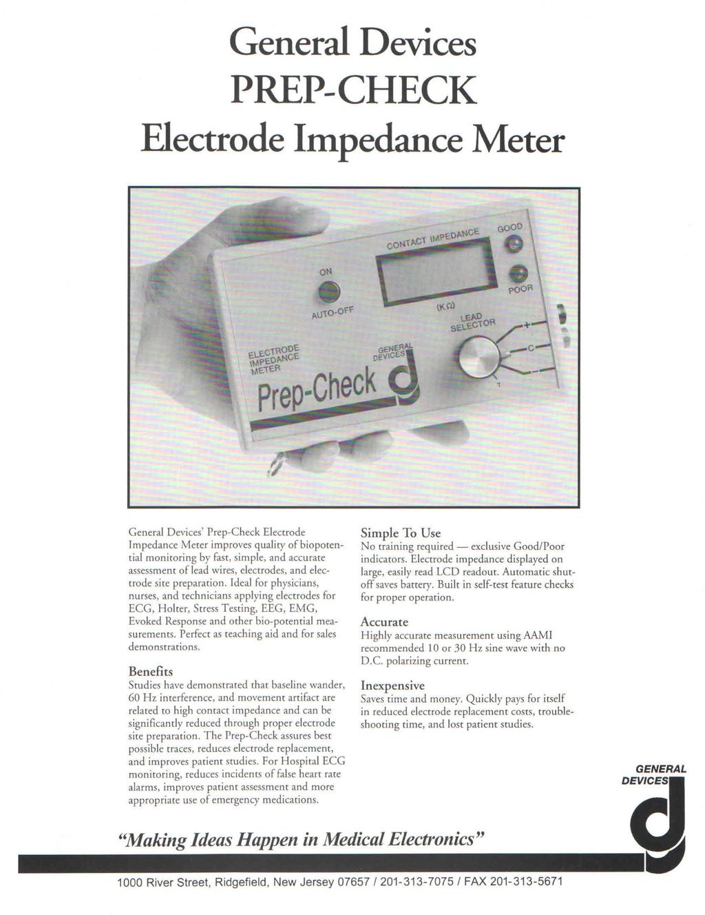
1 Rx FOR ECG MONITORING ARTIFACT By Michael Smith, M.S., B.S.E.E. Introduction The object of electrocardiographic (ECG) monitoring is the observation and assessment of the heart's electrical activity. Cardiac monitoring has become extremely commonplace in recent years in critical care and ambulatory settings. Electronic advancements have produced instrumentation with the potential of providing accurate information and reliable heart rate alarms. Computerized monitors enhance patient assessment by allowing uninterrupted electronic observation of heart rate and ectopic activity with comprehensive automatic reporting mechanisms. Despite these improvements in instrumentation, monitoring systems continue to be plagued by problems related to poor signals. Wandering baselines, small complexes, fuzzy tracings, and frequent electrode replacement make patient assessment difficult and induce false heart rate alarms. Improvement in electrode preparation techniques and a better understanding of the sources of artifact can enhance equipment performance, resulting in improved patient assessment, more effective utilization of nursing time, and reduced operating costs. This article discusses the physiologic and non-physiologic sources of ECG monitoring artifact and presents a method of electrode site preparation to reduce artifact. Sources of ECG Monitoring Artifact The electrical activity of the heart is sensed by monitoring electrodes placed on the skin surface. The electrical signal is very small (normally to volt). These signals are within the frequency range of 0.05 to 100 Hertz (Hz.) or cycles per second. Unfortunately, other artifactual signals of similar frequency and often larger amplitude reach the skin surface and mix with the ECG signals. 9,12 Artifactual signals arise from several internal and external sources. Internal or physiologic sources of artifact are: (1) signals from other muscles (electromyographic signals) and (2) signals produced in the epidermis. External or non-physiologic sources of artifact are: (1) 60 Hz. Pickup, (2) offset signals produced by the electrode itself, (3) signals produced by the interaction of body fluids and the electrode gel, and (4) lead wire and patient cable problems. Physiologic Sources of ECG Artifact Electromyographic (EMG) Signals - All muscle activity produces electrical signals. Signals from muscles other than the heart are called EMG signals and appear on the monitor as narrow, rapid spikes associated with muscle movement. These signals are sufficiently dissimilar to the ECG signals that they can be electronically reduced or "filtered" from the trace. This filtering is readily observed by reduction in the size of EMG signals as the monitor is switched from the diagnostic mode to the monitor mode (in monitors so equipped). Epidermal Signals - The skin is a source of electrical signals which produce motion artifact. Studies have revealed that a voltage of several millivolts can be generated by stretching the epidermis, the outer layer of the skin. 4,5,8,10,11,12 This stretching is the primary source of movement-related (motion) artifact.12 This type of artifact is visible as large baseline shifts occurring when the patient changes positions in bed, eats or ambulates. Epidermal artifact is more troublesome than other types of artifact because: (1) it is difficult to filter electronically and (2) its amplitude is often larger than the ECG signal. 12 Non-Physiologic Sources of ECG Artifact 60 Hz. Pickup - This type of artifact, also called 60 Hz. Interference, produces a wide, fuzzy baseline. It is related to poor electrode contact associated with poor skin preparation techniques, dried electrode gel, or defective patient cables or lead wires. The source of 60 Hz. pickup is the 60 Hz. current which supplies power to the electrical wall outlets. The 60 Hz. energy "radiates" from the electrical wiring in the patient's room and is received in the lead wires and by the patient. The source of radiation cannot be eliminated, but modern monitors can reduce 60 Hz. pickup by filtering and by an electronic technique called common mode rejection. This technique requires good skin contact by all electrodes. One or more electrodes with poor contact will result in the wide fuzzy baseline. Offset Potentials - An offset potential is a voltage that is stored by the electrode. This stored voltage will add to the ECG signal and interfere with it. (The offset potential causes the disappearance of the ECG after defibrillation.) The amount of offset potential and the length of time required for it to dissipate are determined by the materials used for the electrode and the gel. Certain combinations of metals and gels generate large voltages (up to 200 millivolts) with the ability to hold this voltage for long periods of time. Electrode materials such as silver-silver chloride do not allow significant buildup of offset potential, whereas stainless steel electrodes have poor offset characteristics. Most electrodes used for ECG monitoring today are made of silver-silver chloride. With the
2 common use of the silver-silver chloride electrode, offset potentials are no longer considered to be a significant problem. Electrode Gel - until recently, movement of the electrode gel under the electrode was thought to be the primary cause of motion artifact; however, studies have revealed that this effect is minimal. 8,12 The electrode gel does, however, significantly affect the transmission of signals from the skin to the electrode. The lack of sufficient electrode gel, frequently due to evaporation caused by improper storage, results in 60 Hz. pickup and extremely unstable traces. This type of artifact is easily identified by very high electrode impedances (discussed below). Lead Wire and Cable Problems - Breaks in the wires and connections between the electrode and the monitor will always be a source of monitoring problems. Poor contact at any snap connection, loose pins at the cable end of the lead wire, and breaks in the conductors of the lead wire or patient cable can cause intermittent loss of the ECG tracing, 60 Hz. pickup, or trace instability. Electrode Impedance In order for ECG signals to pass from the body to the electrode, an electrically conductive path between the skin and electrode must be established. The conductive ability of this path is referred to as electrode impedance or contact impedance. Electrode impedance is measured in ohms. High impedance decreases the conduction of the ECG signal. Low impedances improve this conduction. The major factors affecting electrode impedance are: (1) the quantity and quality of gel between the electrode and the patient and (2) the degree to which the outer layer of the epidermis (the stratum corneum) has been bridged by the conductive gel. Proper site preparation (as described below) will produce contact impedances of 10,000 ohms or less in 90% of patients. 9 Less than 5,000 ohms is a good target value. Improper site preparation will usually produce contact impedances as high as 100,000 to 200,000 ohms. Interventions to Reduce ECG Artifact To obtain good monitoring tracings, the ECG signal must be as large as possible and the artifact signals as small as possible. Proper preparation of the site is required to accomplish these goals. A brief review of the anatomy of the skin can aid in understanding the rationale for the steps of skin preparation. The skin is composed of the epidermis, the outer layer, and the dermis, which lies beneath the epidermis. The epidermis contains three layers: (1) the stratum germinativum, which is the bottom layer and the layer where epidermal cells originate; (2) the stratum granulosum, the middle layer and the layer where epidermal cells mature, function, and begin to degenerate; and (3) the stratum corneum or "horny layer", the outer layer. The stratum corneum contains flat, dry, deal cells which do not conduct electricity well. These cells can significantly affect the transmission of the ECG signal from the skin to the electrode (i.e., electrode impedance). The stratum granulosum is the layer from which motion artifact is generated. Both the stratum corneum and the stratum granulosum must be prepared properly to achieve good tracings. (See steps one and two below). Remembering these structural components of the skin, one can appreciate the necessity for adequate site preparation. An ideal skin prep consists of four steps: 1. removal of part of the stratum corneum to allow the electrical signals to travel to the electrode. 2. scratching the stratum granulosum to reduce motion potentials generated in this layer. 3. defatting the skin to permit the adhesive base on the electrode to grip the skin. 4. assuring the presence of conductive gel. Step One: Removal of Part of the Stratum Corneum - A variety of methods can be used to remove part of the outer epidermal layer. Vigorous rubbing with a gauze pad, abrading with a rough surface, or gentle abrasion with a sharp material are accepted techniques. The most effective, practical method is gentle abrasion using fine (waterproof) sandpaper, such as 320 to 400 grit wet or dry paper. Such sandpaper is a component of at least one brand of electrode (3M Red Dot). Packaged electrode gels containing sharp, gritty material (such as OmniPrep) also serve this purpose extremely well and should be considered where electrodes without the sandpaper prep are used. The advantage of the sandpaper and the gritty gel method over the other methods is that it removes the unwanted, nonconductive deal cells, with minimal skin damage or irritation. Five to ten gentle strokes can effectively decrease impedance while barely reddening the skin. The contact or electrode impedance can be reduced from 100, ,000 ohms to 1,000-5,000 ohms with this simple technique. Additional benefits are reductions in 60 Hz. pick up and some reduction in motion artifact.
3 Step Two: Scratching the Stratum Granulosum - Fine scratches in the stratum granulosum can be made by the sandpaper and the gritty gels as described above, however, rubbing with gauze pads or rough surfaces has little or no effect on this layer other than to cause irritation. Fine scratches produced by the sandpaper or grit allows the conductive gel to penetrate the stratum granulosum and "short circuit" the epidermal potentials responsible for motion artifact. Five to ten gentle strokes of 220 or 400 grit wet or dry sandpaper or gentle rubbing with a gritty gel can significantly reduce contact impedance and motion artifact. Step Three: Defatting the Skin - Rubbing the skin with an alcohol gauze pad is an acceptable method to remove skin oils. Although acetone is used often instead of alcohol, alcohol is preferred because it provides an adequate degree of fat removal while minimizing skin irritation. Acetone is more irritating to the skin and tends to produce higher contact impedances than alcohol. 8 In addition, acetone presents a fire hazard because it is so highly flammable. Step Four: Assuring the Presence of Conductive Gel - A dry electrode which does not have adequate conducting gel will not work. Although bad batches of electrodes occasionally are received from a manufacturer, most instances of electrode gel dry-out are related to incorrect storage. Electrodes are packaged in metal foil wrappers which are highly impervious to moisture. These wrappers, which help to prevent evaporation of the gel, should not be removed until the electrode is to be used. Electrodes should not be placed in open bins or drawers, and care should be taken to avoid warm storage areas. The electrodes should always be examined for adequate gel prior to application. Electrode stocks should be rotated so that electrodes are used prior to the expiration date, which is usually stamped on the shipping box and the individual package. Packages which contain dried out electrodes, yet are within the expiration date should be returned immediately to the vendor for credit and to alert them to the possibility of a manufacturing problem. Conclusion Artifact in ECG monitoring can be annoying, costly, and dangerous. An understanding of the sources of artifact and care in the application of monitoring electrodes can significantly reduce or even eliminate the problem. Review the sources of artifact and the four-step method for applying electrodes with your staff and continuing education department. You might be pleasantly surprised to see just how good your ECG tracings can become. References: 1. Schmitt, O., and Almasai, J. Electrode Impedance and Voltage Offset as They Effect Efficacy and Accuracy of VCG and ECG Measurements. Proceedings of the XIth International Vectorcardiography Symposium. New York: North Holland Publishing Company. 2. Tortura, G.J., and Anagnostakos, N.P. Principles of Anatomy and Physiology, 3rd ed. New York: Harper and Row Publishing Co., Shackel, B. Skin Drilling: A method of Diminishing Galvanic Skin Potentials. American Journal of Physiology, 72: , Wilcott, R.C. Arousal Sweating and Electrodermal Phenomena. Psychological Bulletin, 67(1): 58-72, Edelberg, R. Local Electrical Response of the Skin to Deformation. Journal of Applied Physiology, 34(3): , Almasai, J., and Schmitt, O. Systematic and Random Variations of Electrode System Impedance. Annals of the New York Academy of Sciences, 170(2): , Johnson, H. Technical and Design Considerations of Disposable Electrodes. Biomedical Electrode Technology and Practice. New York: Academic Press, 67-80, Tam, H.W. and Webster, J.G. Minimizing Electrode Motion Artifact by Skin Abrasion. Institute of Electronic and Electrical Engineers (IEEE) Transactions on Biomedical Engineering (BME), 24(2): , Patterson, R.E. The Characteristics of Some Commercial ECG Electrodes. Journal of Electrocardiology, 11(1): 23-26, Burbank, D.P., and Webster, J.G. Reducing Skin Potential Motion Artifact by Skin Abrasion.. Medical and Biological Engineering and Computing, 16: 31-38, Thakor, N.V., and Webster, J.G. The Origin of Skin Potential and Its Variations. 31st Annual Conference on Engineering in Medicine and Biology (ACEMB), Georgia. Bethesda: Alliance for Engineering and Biology, Odman, S., and Oberg, P. Movement Induced Potentials in Surface Electrodes. Medical Engineering and Computing, 20: , 1982.

4
5
User Guide EMG. This user guide has been created to educate and inform the reader about doing EMG measurements
 User Guide EMG This user guide has been created to educate and inform the reader about doing EMG measurements For more information about NeXus, our BioTrace+ software, please visit our website or contact
How to Set Up Continuous EEG (CEEG)
") How to Set Up Continuous EEG (CEEG) OBTAIN SUPPLIES 1. EEG module (yellow) 2. EEG cable with wires 3. NuPrep cream and a face cloth 4. Paediatric electrodes (use new package) STORING Location All supplies
How to Set Up Continuous EEG (CEEG) OBTAIN SUPPLIES 1. EEG module (yellow) 2. EEG cable with wires 3. NuPrep cream and a face cloth 4. Paediatric electrodes (use new package) STORING Location All supplies
Improving ECG quality*
 Clinical Services earning series Improving ECG quality* The quality of your ECG diagnosis depends on the accuracy of the ECG signal. This in turn relies on making a good electrical contact, and placing
EGM Einthoven Goldberger Module Type 701
 Operating Instructions for the PLUGSYS Module EGM Einthoven Goldberger Module Type 701 ECG amplifier for bipolar extremity leads after Einthoven and unipolar extremity leads after Goldberger (Version:
OPERATION / SERVICE MANUAL
 OPERATION / SERVICE MANUAL Part Number: 3 100 1045 Revision G Table of Contents A WORD OF THANKS... II PRECAUTIONS... III I. GENERAL INFORMATION... 1 Description... 1 A. Key Components... 2 Patient Event
User Guide. qeeg NeXus-32. This user guide has been created to educate and inform the reader about doing qeeg measurements with the NeXus-32
 User Guide qeeg NeXus-32 This user guide has been created to educate and inform the reader about doing qeeg measurements with the NeXus-32 For more information about NeXus, our BioTrace+ software, please
VivoSense. User Manual Galvanic Skin Response (GSR) Analysis Module. VivoSense, Inc. Newport Beach, CA, USA Tel. (858) , Fax.
 Analysis Module. VivoSense, Inc. Newport Beach, CA, USA Tel. (858) , Fax.") VivoSense User Manual Galvanic Skin Response (GSR) Analysis VivoSense Version 3.1 VivoSense, Inc. Newport Beach, CA, USA Tel. (858) 876-8486, Fax. (248) 692-0980 Email: info@vivosense.com; Web: www.vivosense.com
VivoSense User Manual Galvanic Skin Response (GSR) Analysis VivoSense Version 3.1 VivoSense, Inc. Newport Beach, CA, USA Tel. (858) 876-8486, Fax. (248) 692-0980 Email: info@vivosense.com; Web: www.vivosense.com
TASTEPROBE Type DTP-1. Pre-amplifier for recording from contact chemosensilla INSTRUCTIONS
 TASTEPROBE Type DTP-1 Pre-amplifier for recording from contact chemosensilla INSTRUCTIONS SYNTECH 2002 Hilversum, The Netherlands Reproduction of text and/or drawings is permitted for personal use. The
Lesson 14 BIOFEEDBACK Relaxation and Arousal
 Physiology Lessons for use with the Biopac Student Lab Lesson 14 BIOFEEDBACK Relaxation and Arousal Manual Revision 3.7.3 090308 EDA/GSR Richard Pflanzer, Ph.D. Associate Professor Indiana University School
RoHS. Atma-Sphere Music Preamplifier. model P-2 OWNER'S MANUAL. Please study this document carefully before using equipment
 1742 Selby Av. St. Paul, MN 55104 651 690 2246 atma sphere.com Atma-Sphere Music Preamplifier model P-2 OWNER'S MANUAL Please study this document carefully before using equipment RoHS CONGRATULATIONS!
PanelView 1400e CRT Maintenance
 Release Note PanelView 1400e CRT Maintenance Maximizing the life of your PanelView 1400e, CRT Terminals To maximize the life of a CRT, the following is strongly recommended: Adjust the external brightness
Mapletree Audio Design
 Ultra 4C Preamplifier Mapletree Audio Design Ultra 4C Stereo Phono/Line Preamplifier PS 2D Power Supply User s Manual Rev. Mar. 22, 2019 Mapletree Audio Design R. R. 1, Seeley's Bay, Ontario, Canada, K0H
Self Excited Automatic Voltage Regulator For Generator Compatible with Marathon SE350* Operation Manual
 Self Excited Automatic Voltage Regulator For Generator Compatible with Marathon SE350* Operation Manual s * Use for reference purpose only and not a genuine Marathon product. 1. INTRODUCTION Sensing Input
EA350. Generator Automatic Voltage Regulator Operation Manual
 Generator Automatic Voltage Regulator Operation Manual Self Excited Automatic Voltage Regulator For General Generators Compatible with Marathon SE350* * Use for reference purpose only and not a genuine
Heart Rate Variability Preparing Data for Analysis Using AcqKnowledge
 APPLICATION NOTE 42 Aero Camino, Goleta, CA 93117 Tel (805) 685-0066 Fax (805) 685-0067 info@biopac.com www.biopac.com 01.06.2016 Application Note 233 Heart Rate Variability Preparing Data for Analysis
DA VGA Line Receiver User s Guide
 Welcome! We greatly appreciate your purchase of the DA103-217 VGA Line Receiver. We are sure you will find it reliable and simple to use. Superior performance for the right price, backed by solid technical
EXA PH200/400 and EXA PH202/402 Troubleshooting and Error Code Guide
 EXA PH200/400 and EXA PH202/402 Troubleshooting and Error Code Guide Introduction The EXA Series of Instruments (EXA PH200, PH400, PH202, PH402) provide much more than just a measurement. They are also
A Guide to Selecting the Right EMG System
 Motion Lab Systems, Inc. 15045 Old Hammond Hwy, Baton Rouge, LA 70816 June 20, 2017 A Guide to Selecting the Right EMG System Everyone wants to get the best value for money and there are a lot of EMG systems
Introduction: Overview. EECE 2510 Circuits and Signals: Biomedical Applications. ECG Circuit 2 Analog Filtering and A/D Conversion
 EECE 2510 Circuits and Signals: Biomedical Applications ECG Circuit 2 Analog Filtering and A/D Conversion Introduction: Now that you have your basic instrumentation amplifier circuit running, in Lab ECG1,
ECG Demonstration Board
 ECG Demonstration Board Fall 2012 Sponsored By: Texas Instruments Design Team : Matt Affeldt, Alex Volinski, Derek Brower, Phil Jaworski, Jung-Chun Lu Michigan State University Introduction: ECG boards
INSTALLATION MANUAL FT-FOTR-1VDE-ST-S
 INSTALLATION MANUAL FT-FOTR-1VDE-ST-S 1-Channel Digital Duplex Baseband Video Transmitter and Receiver With Reverse Data Transmission & Ethernet Transmission v1.0 4/5/11 1 PACKAGE CONTENTS This package
CM-1UTP CAMERA MASTER UTP ADAPTOR
 CM-1UTP CAMERA MASTER UTP ADAPTOR INSTRUCTION BOOK CM-1UTP.ISB TABLE OF CONTENTS FORWARD 2 VIDEO STANDARDS 2 COAXIAL CABLE vs UTP WIRE CABLE 3 MEASUREMENT 3 MOUNTING THE CM1-UTP ADAPTOR 3 UTP WIRE CABLE
Guide to the Inspection of Printed Products
 Guide to the Inspection of Printed Products Manager, Printing Procurement Division Constitution Square 360 Albert St., 12th Floor Ottawa, Ontario, K1A 0S5, CANADA Guide to the Inspection of Printed Products
HeartLogix HLI Heart Monitor. Patient Instructions. To activate your monitor or for questions call
 HeartLogix HLI Heart Monitor Patient Instructions To activate your monitor or for questions call 1-855-751-3131 Contents of Kit HeartLogix Monitor Case e holter Monitor Case Holster Battery Charger Patient
DISTRIBUTION AMPLIFIER
 MANUAL PART NUMBER: 400-0045-005 DA1907SX 1-IN, 2-OUT VGA/SVGA/XGA/UXGA DISTRIBUTION AMPLIFIER USER S GUIDE TABLE OF CONTENTS Page PRECAUTIONS / SAFETY WARNINGS... 2 GENERAL...2 GUIDELINES FOR RACK-MOUNTING...2
Operation Manual for. SCU1 Signal Conditioning Unit
 Operation Manual for SCU1 Signal Conditioning Unit Table of Contents 1. About this Manual 4 1.1. Symbols Glossary 4 2. Safe Use 4 3. Compatible Magnetometers 5 4. Introduction to the SCU1 5 4.1. Summary
The Bio Tuner Model BT8 Manual
 The Bio Tuner Model BT8 Manual CONTENTS WELCOME TO SOTA... 2 BEFORE USING... 2 LEARN MORE... 2 COMPLETE UNIT INCLUDES... 2 DO NOT USE... 3 CAUTIONS... 3 SUMMARY OF LIGHTS... 4 HOW TO USE THE BIO TUNER...
Preparation of the participant. EOG, ECG, HPI coils : what, why and how
 Preparation of the participant EOG, ECG, HPI coils : what, why and how 1 Introduction In this module you will learn why EEG, ECG and HPI coils are important and how to attach them to the participant. The
In-Line or 75 Ohm In-Line
 or 5 Ohm 1dB Adjustable Gain 800/1900 Smart Technology Contents: Quick Install Overview.... 2 Installation Diagram.... Understanding the Lights... 9 Warnings and Recommendations....11 Appearance of device
The Bio Tuner. Model BT7 Manual
 The Bio Tuner Model BT7 Manual CONTENTS WELCOME TO SOTA... 2 BEFORE USING... 2 LEARN MORE... 2 COMPLETE UNIT INCLUDES... 2 DO NOT USE... 3 CAUTIONS... 3 SUMMARY OF LIGHTS... 4 HOW TO USE THE BIO TUNER...
May result in personal injury or property loss. Indicate the behaviors that must be prohibited
 User Manual VXM143U Please read this manual carefully for proper usage before lnstallatlon and use. It is recommended to keep this manual for future check. The pictures in this manual are only for reference.
INSTRUMENTATION ESSENTIALS: DIFFERENTIAL AMPLIFICATION
 INSTRUMENTATION ESSENTIALS: DIFFERENTIAL AMPLIFICATION Daniel Dumitru, M.D., Ph.D. University of Texas Health Science Center San Antonio, Texas 1 ELECTRODE DESIGNATIONS E-1: Active Electrode (G-1) Located
USB-TG124A Tracking Generator User Manual
 USB-TG124A Tracking Generator User Manual Signal Hound USB-TG124A User Manual 2017, Signal Hound, Inc. 35707 NE 86th Ave La Center, WA 98629 USA Phone 360.263.5006 Fax 360.263.5007 This information is
Electrocardiogram (ECG) Version Date: 2017-FEB-15 Document Effective Date: 2017-MAY-15
 Version Date: 2017-FEB-15 Document Effective Date: 2017-MAY-15") Title: Electrocardiogram (ECG) Version Date: 2017-FEB-15 Document Effective Date: 2017-MAY-15 Number: Data Collection Site (DCS) Version: 2.4 Number of Pages: SOP_DCS_0009 5 1.0 Purpose: The purpose of
Title: Electrocardiogram (ECG) Version Date: 2017-FEB-15 Document Effective Date: 2017-MAY-15 Number: Data Collection Site (DCS) Version: 2.4 Number of Pages: SOP_DCS_0009 5 1.0 Purpose: The purpose of
INSTALLATION MANUAL. ST-CVTMD420-WPIR-W Covert Motion Detection Color Camera. v1.3 8/11/11 1
 INSTALLATION MANUAL ST-CVTMD420-WPIR-W Covert Motion Detection Color Camera v1.3 8/11/11 1 PACKAGE CONTENTS This package contains: One ST-CVTMD420-WPIR-W covert motion detection camera One installation
BeneHeart R3. Electrocardiograph
 Peripherals and Communications USB Drive PC barcode reader USB printer wired wireless The Glasgow algorithm is the first to be based on specific variables, including age, gender, race, medication, and
Model 1421 Distribution Amplifier
 Model 1421 Distribution Amplifier Installation and Operating Instructions The 1421 Distribution Amplifier provides four independent, wide bandwidth outputs from one video input. The unit is color compatible
AWT150C/AWT150CS/ AWT151C CCD Camera
 AWT150C/AWT150CS/ AWT151C CCD Camera ISSUED OCTOBER 2018 WARNING Failure to follow all instructions and safety precautions in this manual, in the vehicle and body manufacturers' manuals and on the safety
NDT Supply.com 7952 Nieman Road Lenexa, KS USA
 ETher ETherCheck Combined Eddy Current & Bond Testing Flaw Detector The ETherCheck is a combined Eddy Current and Bond Testing Flaw Detector which comes with a rich range of features offered by a best
Muscle Sensor KI 2 Instructions
 Muscle Sensor KI 2 Instructions Overview This KI pre-work will involve two sections. Section A covers data collection and section B has the specific problems to solve. For the problems section, only answer
Scotch Heavy Duty Vinyl Electrical Tape 22
 Scotch Heavy Duty Vinyl Electrical Tape 22 Data Sheet July 2015 Description Agency Approvals & Self Certifications Scotch Heavy Duty Vinyl Electrical Tape 22 is a premium grade, 10-mil thick, vinyl insulating
Rotor Blade Protection Kit 8999K11
 3 Rotor Blade Protection Kit 8999K11 June 2010 Product Description The components in this kit may be used to protect the leading edge of rotor blades on heavy lift helicopters. This application uses 8-inch
SedLine Sedation Monitor
 SedLine Sedation Monitor Quick Reference Guide Not intended to replace the Operator s Manual. See the SedLine Sedation Monitor Operator s Manual for complete instructions, including warnings, indications
Interaction of Infrared Controls And Fluorescent Lamp/Ballast Systems In Educational Facilities
 LSD 6-1999 A NEMA Lighting Systems Division Document Interaction of Infrared Controls And Fluorescent Lamp/Ballast Systems In Educational Facilities Prepared by Lamp Section Ballast Section National Electrical
Copyright 2008 Society of Manufacturing Engineers. FUNDAMENTALS OF TOOL DESIGN Progressive Die Design
 FUNDAMENTALS OF TOOL DESIGN Progressive Die Design SCENE 1. PD06A, tape FTD29, 09:14:22:00-09:14:48:00 pan, progressive die operation PROGRESSIVE DIES PERFORM A SERIES OF FUNDAMENTAL CUTTING AND FORMING
MEE 1000A. For more than 50 years, healthcare. Neuromaster MEE-1000A Intra-Operative Monitoring System
 IOM Data Acquisition System epilepsy monitoring electroencephalography ambulatory recording polysomnography icu/or monitoring electromyography ncv evoked potentials IOM MEE 000A Neuromaster MEE-000A Intra-Operative
OPERATION NOTES FOR PSIDEX AUDIO PGP-1A PRE-AMPLIFIER DESCRIPTION INSTALLATION
 OPERATION NOTES FOR PSIDEX AUDIO PGP-1A PRE-AMPLIFIER DESCRIPTION The Psidex Audio Laboratory PGP- 1A is a vacuum tube based microphone preamp and program line amplifier designed to provide solid, robust
Light Emitting Diodes (LEDs)
") Light Emitting Diodes (LEDs) Example: Circuit symbol: Function LEDs emit light when an electric current passes through them. Connecting and soldering LEDs must be connected the correct way round, the diagram
Light Emitting Diodes (LEDs) Example: Circuit symbol: Function LEDs emit light when an electric current passes through them. Connecting and soldering LEDs must be connected the correct way round, the diagram
ALO 030 MKII. 30 Watt DMX LED scanner. User manual
 ALO 030 MKII 30 Watt DMX LED scanner User manual Safety instructions WARNING! Always keep this device away from moisture and rain! Hazardous electrical shocks may occur! WARNING! Only connect this device
MAAP DIEEV1. Ka-Band 4 W Power Amplifier GHz Rev. V1. Features. Functional Diagram. Description. Pin Configuration 2
 Features Frequency Range: 32 to Small Signal Gain: 18 db Saturated Power: 37 dbm Power Added Efficiency: 23% % On-Wafer RF and DC Testing % Visual Inspection to MIL-STD-883 Method Bias V D = 6 V, I D =
DMX 512 Language Date: Venerdì, febbraio 12:15:08 CET Topic: Educational Lighting Site
 DMX 512 Language Date: Venerdì, febbraio 15 @ 12:15:08 CET Topic: Educational Lighting Site DMX512 Cable Connectors Principles of functioning Distaces Terminations Splitter & Buffer DMX 1990 Until a few
Elcometer Circular Ball Type. Drying Time Recorder. Operating Instructions
 English Elcometer 5500 Circular Ball Type Drying Time Recorder Operating Instructions English The Elcometer 5500 Circular Ball Type Drying Time Recorder has been tested in accordance with EU Regulations
EMI/EMC diagnostic and debugging
 EMI/EMC diagnostic and debugging 1 Introduction to EMI The impact of Electromagnetism Even on a simple PCB circuit, Magnetic & Electric Field are generated as long as current passes through the conducting
Design of Medical Information Storage System ECG Signal
 Design of Medical Information Storage System ECG Signal A. Rubiano F, N. Olarte and D. Lara Abstract This paper presents the design, implementation and results related to the storage system of medical
ASK THE EXPERTS: Procedure for Verifying Magnetic Pickup Signal Integrity Using a Windrock Portable Analyzer
 December 2016 ASK THE EXPERTS: Procedure for Verifying Magnetic Pickup Signal Integrity Using a Windrock Portable Analyzer QUESTION: Does Windrock have some standard procedures for verifying magnetic pickup
ROUGH DRAFT. Guide. Installation. Signal Booster. Wilson. AG Pro 75 Smart Technology In-Building Wireless 800/1900 Signal Booster.
 Signal Booster Installation Guide Contents: AG Pro 75 Smart Technology In-Building Wireless 800/1900 Signal Booster Before Getting Started.... 1 Antenna Options & Accessories.................... 1 Easy
COMMODORE 1802 COLOR MONITOR USER'S GUIDE
 COMMODORE 1802 COLOR MONITOR USER'S GUIDE Warning: This product includes critical mechanical and electrical parts which are essential for X radiation safety. For continued safety replace critical components
INSTALLATION MANUAL FT-FOTR-8VD-ST-S. 8-Channel Digital Duplex Baseband Video Transmitter and Receiver With Reverse Data Transmission for PTZ Cameras
 INSTALLATION MANUAL FT-FOTR-8VD-ST-S 8-Channel Digital Duplex Baseband Transmitter and Receiver With Reverse Transmission for PTZ Cameras v1.0 4/5/11 1 PACKAGE CONTENTS This package contains: One each
INSTALLATION MANUAL. ST-CVTSD520-WSD-W Smoke Detector Covert Camera. v1.2 8/11/11 1
 INSTALLATION MANUAL ST-CVTSD520-WSD-W Smoke Detector Covert Camera v1.2 8/11/11 1 PACKAGE CONTENTS This package contains: One ST-CVTSD520-WSD-W smoke detector covert camera One installation manual Mounting
Mini Electronic Pulse Massager
 Mini Electronic Pulse Massager UC-029 Operating Manual Contents Introduction...2 Safety warnings....3 Part identification 4 Operating instructions...5 Program schematics....6-8 Recommended use points......8
Dynatel Advanced Cable Locator 2250
 3 Dynatel Advanced Cable Locator 2250 Quickly and Accurately Identify Underground Assets Pinpoint exact cable path and depth quickly and easily with this lightweight, easy-to-handle unit The 3M Dynatel
Wired Troubleshooting Manual
 Wired Troubleshooting Manual Congratulations on your choice of this product. Its superior sound reproduction will provide enjoyment and entertainment. We appreciate your patronage and take pride in the
USER MANUAL. DE-1 Police-light. CAUTION! Keep this device away from rain and moisture! Unplug mains lead before opening the housing!
 USER MANUAL DE-1 Police-light CAUTION! Keep this device away from rain and moisture! Unplug mains lead before opening the housing! For your own safety, please read this user manual carefully before you
MAW218D7. User s manual. Pol.Ind.Norte-Perpinyà, TERRASSA (Barcelona-SPAIN)
") MAW218D7 User s manual Pol.Ind.Norte-Perpinyà,25 08226 TERRASSA (Barcelona-SPAIN) info@master-audio.com www.master-audio.com Nov 2008 CAUTION RISK OF ELECTRIC SHOCK DON T OPEN WARNING: To reduce the risk
MAW218D7 User s manual Pol.Ind.Norte-Perpinyà,25 08226 TERRASSA (Barcelona-SPAIN) info@master-audio.com www.master-audio.com Nov 2008 CAUTION RISK OF ELECTRIC SHOCK DON T OPEN WARNING: To reduce the risk
INSTRUCTION MANUAL. Made in the U.S.A. by USA Dance Floor. Copyright 2017 USA Dance Floor, LLC
 1 INSTRUCTION MANUAL Made in the U.S.A. by USA Dance Floor Copyright 2017 USA Dance Floor, LLC 2 BEFORE YOU BEGIN Plan ahead! First read all of this manual and get familiar with all of the parts. Failing
Colour Explosion Proof Video Camera USER MANUAL VID-C
 Colour Explosion Proof Video Camera USER MANUAL VID-C Part Number: MAN-0036-00 Rev 4 Copyright 2002 Net Safety Monitoring Inc. Printed in Canada This manual is provided for informational purposes only.
DELSYS. Bagnoli TM EMG System User s Guide
 DELSYS Bagnoli TM EMG System User s Guide Bagnoli TM EMG System User s Guide PM-B05 Copyright by Delsys Incorporated Specifications and procedures outlined in this document are subject to change without
WESAUDIO 4/25/16 TIMBRE USER MANUAL. Timbre. User manual EN. Copyright 2016 by WesAudio
 www.wesaudio.com Timbre User manual EN Copyright 2016 by WesAudio 1 Thank You for the purchase of Timbre Timbre All tube Vari-mu mono compressor. With kind regards Radoslaw Wesolowski 2 Table of Contents
Installation Manual Original Instructions - IW4001
 Installation Manual Original Instructions - IW4001 Installation Manual 1 General Operator and Supervisor Information Signal Word Definition Signal Word Panel Table of Contents Operator and Supervisor Information
3M Cold Shrink QS-III Silicone Rubber Splice Kit 5488A-TOW/WOT
 3M Cold Shrink QS-III Silicone Rubber Splice Kit 5488A-TOW/WOT For Tape Over Wire (TOW) and Wire-Over-Tape (WOT) Shielded Cable For 250 2000 kcmil cable with 650-mil primary insulation thickness Instructions
MEE 1000A. Neuromaster MEE-1000A. Intra-Operative Monitoring System
 IOM Data Acquisition System Neuromaster MEE-000A MEE 000A epilepsy monitoring electroencephalography ambulatory recording ICU/or monitoring polysomnography out of center sleep testing electromyography
BIRD 2. Owners manual MADE IN SWEDEN
 BIRD 2 Owners manual 1 MADE IN SWEDEN Table of contents Introduction Marten Philosophy Unpacking Quick Setup Connecting the loudspeakers 2 3 3 4 4 5 Choosing cables Connections Burn-in Room Acoustics Positioning
medlab One Channel ECG OEM Module EG 01000
 medlab One Channel ECG OEM Module EG 01000 Technical Manual Copyright Medlab 2012 Version 2.4 11.06.2012 1 Version 2.4 11.06.2012 Revision: 2.0 Completely revised the document 03.10.2007 2.1 Corrected
Gamma Cardio Soft. Gamma Cardio CG ECG Multifunctional System. User Manual
 Gamma Cardio Soft Gamma Cardio CG ECG Multifunctional System User Manual Revision 1.22 14/02/2013 Gamma Cardio Soft Srl via Felice Cascione 10, 00128 Rome, www.gammacardiosoft.it Gamma Cardio CG User Manual
Home Monitoring. Wired Color Camera. User Manual. For indoor/outdoor use. Do not use in wet locations.
 45231 Home Monitoring Wired Color Camera User Manual For indoor/outdoor use. Do not use in wet locations. www.jascoproducts.com 1-800-654-8483 2 Thank you for purchasing the GE 45231 Wired Color Camera.
User Guide. Centrex Recording Interface
 User Guide Centrex Recording Interface Table of Contents Introduction... 2 The Meridian Business Set... 3 Key Numbering Plan (18 button add-on)... 4 Key Numbering Plan (36 button add-on)... 5 Key Numbering
Concert Series ORDERCODE D3470 ORDERCODE D3471 ORDERCODE D3472 D3470 D3471 D3472
 Concert Series ORDERCODE D3470 ORDERCODE D3471 ORDERCODE D3472 D3470 D3471 D3472 Congratulations! You have bought a great, innovative product from DAP Audio. The DAP Audio Concert Series brings excitement
DA1909 COMPUTER VIDEO LINE DRIVER WITH EQUALIZATION USER S GUIDE
 MANUAL PART NUMBER: 400-0108-002 PRODUCT REVISION: 1 COMPUTER VIDEO LINE DRIVER WITH EQUALIZATION USER S GUIDE INTRODUCTION Altinex appreciates your purchase of the Line Driver. We are sure you will find
PACSystems* RX3i. Isolated Thermocouple Input Module, 6 Channels, IC695ALG306-EB Isolated Thermocouple Input Module, 12 Channels, IC695ALG312-EB
 September 2013 PACSystems* RX3i Isolated Thermocouple Input Module, 6 Channels, IC695ALG306-EB Isolated Thermocouple Input Module, 12 Channels, IC695ALG312-EB Isolated +24 VDC Power Isolated Thermocouple
Reciprocating Machine Protection
 Reciprocating Machine Protection Why You Should Be Monitoring the Needle Instead of the Haystack By: John Kovach, President, Riotech Instruments Ltd LLP Frank Fifer, Director of Operations, Peerless Dynamics,
Lesson 10 Manual Revision BIOPAC Systems, Inc.
 Physiology Lessons for use with the Lesson 10 ELECTROOCULOGRAM (EOG) I Eye Movement Saccades and Fixation during Reading Manual Revision 3.7.3 061808 Vertical J.C. Uyehara, Ph.D. Biologist BIOPAC Systems,
Thank you for purchasing a qualiton APR204 preamplifier!
 Introduction Thank you for purchasing a qualiton APR204 preamplifier It is designed to deliver a high standard of musical performance. The innovation in engineering and manufacturing this product guarantees
10.4" LCD Monitor with Aluminum Front Bezel YPM1040PHB
 SPECIFICATION FOR APPROVAL M0DEL: 10.4" LCD Monitor with Aluminum Front Bezel YPM1040PHB BASE MODEL Customer's Confirmation Approved by: Reviewed by: Prepared by: Supplier's Confirmation Approved by: Reviewed
Chapter 1. Introduction to Digital Signal Processing
 Chapter 1 Introduction to Digital Signal Processing 1. Introduction Signal processing is a discipline concerned with the acquisition, representation, manipulation, and transformation of signals required
American Power Design, Inc.
 FEATURES 4 Customer Selects Output Voltage 4 Outputs to 8000 Vdc 4 Proportional Output Voltage 4 Six-Sided Shielded Case 4 60 khz Switching Frequency 4 5000 Vdc Output Isolation 4 Continuous Short Circuit
Practical considerations of accelerometer noise. Endevco technical paper 324
 Practical considerations of accelerometer noise Endevco technical paper 324 Practical considerations of accelerometer noise Noise can be defined as any undesirable signal within the measurement chain.
LCD VALUE SERIES (32 inches)
") LCD VALUE SERIES (32 inches) http://www.orionimages.com All contents of this document may change without prior notice, and actual product appearance may differ from that depicted herein 1. SAFETY INSTRUCTION
LCD VALUE SERIES (32 inches) http://www.orionimages.com All contents of this document may change without prior notice, and actual product appearance may differ from that depicted herein 1. SAFETY INSTRUCTION
Utility Amplifier GA6A Model
 Utility Amplifier GA6A Model Installation and Use Manual 2004 Bogen Communications, Inc. All rights reserved. Specifications subject to change without notice. 54-5757-03D 1503 NOTICE: Every effort was
Please take a few minutes to read this manual so that you will better understand the featues and capabilities of your MF80. MF80 Owner s Manual 1
 Congratulations on your purchase of the Conrad-Johnson MF80 amplifier. You have acquired one of the finer pieces of musical reproduction equipment available today. The MF80 is the result of over a decade
DA IN 1-OUT LINE DRIVER WITH EQUALIZATION + AUDIO USER S GUIDE
 MANUAL PART NUMBER: 400-0430-001 1-IN 1-OUT LINE DRIVER WITH UALIZATION + AUDIO USER S GUIDE TABLE OF CONTENTS Page PRECAUTIONS / SAFETY WARNINGS... 2 GENERAL...2 GUIDELINES FOR RACK-MOUNTING...2 INSTALLATION...2
DVM-3000 Series 12 Bit DIGITAL VIDEO, AUDIO and 8 CHANNEL BI-DIRECTIONAL DATA FIBER OPTIC MULTIPLEXER for SURVEILLANCE and TRANSPORTATION
 DVM-3000 Series 12 Bit DIGITAL VIDEO, AUDIO and 8 CHANNEL BI-DIRECTIONAL FIBER OPTIC MULTIPLEXER for SURVEILLANCE and TRANSPORTATION Exceeds RS-250C Short-haul and Broadcast Video specifications. 12 Bit
DEM B SBH-PW-N (A-TOUCH)
") DISPLAY Elektronik GmbH LCD MODULE DEM 128128B SBH-PW-N (A-TOUCH) Version :2 28/Dec/2007 GENERAL SPECIFICATION MODULE NO. : DEM 128128B SBH-PW-N (A-TOUCH) CUSTOMER P/N VERSION NO. CHANGE DESCRIPTION DATE
DISPLAY Elektronik GmbH LCD MODULE DEM 128128B SBH-PW-N (A-TOUCH) Version :2 28/Dec/2007 GENERAL SPECIFICATION MODULE NO. : DEM 128128B SBH-PW-N (A-TOUCH) CUSTOMER P/N VERSION NO. CHANGE DESCRIPTION DATE
DVI DL Super Booster Plus EXT-DVI-141DLBP. User Manual
 DVI DL Super Booster Plus EXT-DVI-141DLBP User Manual Congratulations on your purchase of the DVI DL Super Booster Plus. Your complete satisfaction is very important to us. Gefen Gefen delivers innovative,
Re: ENSC 370 Project Physiological Signal Data Logger Functional Specifications
 School of Engineering Science Simon Fraser University V5A 1S6 versatile-innovations@sfu.ca February 12, 1999 Dr. Andrew Rawicz School of Engineering Science Simon Fraser University Burnaby, BC V5A 1S6
White Paper. Uniform Luminance Technology. What s inside? What is non-uniformity and noise in LCDs? Why is it a problem? How is it solved?
 White Paper Uniform Luminance Technology What s inside? What is non-uniformity and noise in LCDs? Why is it a problem? How is it solved? Tom Kimpe Manager Technology & Innovation Group Barco Medical Imaging
Low Noise Solid State Phono Preamplifier User's Guide and Operating Information
 Bel Canto Design PHONO 1 Low Noise Solid State Phono Preamplifier User's Guide and Operating Information Bel Canto Design 212 Third Avenue North Suite 345 Minneapolis, MN 55401 Phone: (612) 317.4550 Fax:
Color Video Monitor. Instruction Manual. Read this manual thoroughly before use, and retain it for maintenance.
 Color Video Monitor Instruction Manual Read this manual thoroughly before use, and retain it for maintenance. The product s exterior design and specifications may subject to change without prior notice
NIHR Southampton Biomedical Research Centre
 The NIHR Southampton (BRC) has a tight quality assurance system for the writing, reviewing and updating of Standard Operating Procedures. As such, version-controlled and QA authorised Standard Operating
Identification of Motion Artifact in Ambulatory ECG Signal Using Wavelet Techniques
 American Journal of Biomedical Engineering 23, 3(6): 94-98 DOI:.5923/j.ajbe.2336.8 Identification of Motion Artifact in Ambulatory ECG Signal Using Wavelet Techniques Deepak Vala,*, Tanmay Pawar, V. K.
MDA-2-HV. 1x2 Moblie Distribution Amplifier. Instruction Manual
 MDA-2-HV 1x2 Moblie Distribution Amplifier Instruction Manual Thank you for purchasing one of our products. Please read this manual before using this product. When using this product, always follow the