INSTRUMENTATION ESSENTIALS: DIFFERENTIAL AMPLIFICATION
|
|
|
- Tamsin Holland
- 5 years ago
- Views:
Transcription

1 INSTRUMENTATION ESSENTIALS: DIFFERENTIAL AMPLIFICATION Daniel Dumitru, M.D., Ph.D. University of Texas Health Science Center San Antonio, Texas 1
2 ELECTRODE DESIGNATIONS E-1: Active Electrode (G-1) Located Over Active Tissue To Be Recorded E-2: Reference Electrode (G-2) Located At Some Distance From E-1 Ground: Sets The Relative Zero Value For Instrument AMPLIFIERS 2
3 AMPLIFIER DEFINITIONS Gain: Amplifier Output/Amplifier Input Input: 10 uv; Output: 10,000 uv = Gain 1000 Sensitivity: Ratio Of Amplifier Input To CRT Deflection 1 cm Deflection For 10 uv Input: 10uV/Div 3
4 DIFFERENTIAL AMPLIFICATION DIFFERENTIAL AMPLIFICATION Two Amplifiers With Essentially But Not Quite Identical Characteristics Positive Or Non-inverting Amplifier Amplifies But Does Not Alter Response Polarity Negative Or Inverting Amplifier Amplifies And Inverts Response Polarity The Two Inputs Are Electrically Summted Net Result Is Magnification Of Dissimilar Signals And Cancellation Of Similar Signals 4

5 DIFFERENTIAL AMPLIFICATION AMPLIFIERS The Biologic Signal Of Interest Is Split Between The Electrode And The Amplifier. What Is Not Lost At The Electrode Passes On To The Amplifier For Us To Observe Etotal = Eelec + Eamp The Current From The Signal Is The Same For Both The Electrode And Amplifier But The Voltage Drop Is Different For Each Depending On Their Respective Impedances (Ohms Law) 5


6 MATH X 2 SERIES CIRCUIT 6
7 AMPLIFIERS OHMS LAW: E = IR or E=IZ E= Voltage Of The Biologic/Environmental Signals I= Current Associated With The Signal Z= Impedance of Electrode/Amplifier Signal Voltage Forms Series Circuit With I & Z Etotal = Eelec + Eamp Eelec=I X Zelec Eamp=I X Zamp SERIES CIRCUIT 7
8 AMPLIFIERS Etotal = Eelec + Eamp Can Use Ohm s Law To Help Understand What The Instrument Is Doing And How That Can Help Us Solve Interference Issues AMPLIFIERS Etotal = Eelec + Eamp Etotal = I X Zelec + I X Zamp Etotal = I (Zelec + Zamp) We Are Interested In The Amplifier Eamp = I X Zamp; or I =Eamp/Zamp Etotal = Eamp/Zamp X (Zelec + Zamp) Eamp = (Etotal) (Zamp)/Zelec + Zamp 8
9 RELATIONSHIPS BETWEEN ELECTRODES/AMPLIFIERS E amp1 = E t ( Z amp1 ) Z elec1 + Z amp1 E amp2 = E t (Z amp2 ) Z elec2 + Z amp2 E amp1 E amp2 = E total RELATIONSHIPS BETWEEN ELECTRODES/AMPLIFIERS E amp1 = E t ( Z amp1 ) ; What If Z elec1 is tiny Z elec1 + Z amp1 E amp1 = E t (Z amp1 )/Z amp1 E amp1 = E t 9
/2 Z amp1 = Et/2 Cuts Our Signal In Half; False Positive Axonal Loss?")

10 RELATIONSHIPS BETWEEN ELECTRODES/AMPLIFIERS E amp1 = E t ( Z amp1 ) ; What If Z elect1 Is Big (= amp) Z elec1 + Z amp1 Z elec1 + Z amp1 = 2 Z amp1 E amp1 = E t (Z amp1 )/2 Z amp1 = Et/2 Cuts Our Signal In Half; False Positive Axonal Loss? RELATIONSHIPS BETWEEN ELECTRODES/AMPLIFIERS E amp1 = E t ( Z amp1/ Z elec1 + Z amp1 ) ; What If Z elect1 Is Big (= amp) Our Desired Signal Is Cut In Half But, What About The Common Signal If The Two Electrodes See Half Each Others Common Signal IT IS MULTIPLIED NOT SUBTRACTED OUT THROUGH DIFFERENTIAL AMPLIFICATION Result: Big 60Hz & Signal Is Lost In The Noise 10
 - E t (Z amp2 ) Z")

11 RELATIONSHIPS BETWEEN ELECTRODES/AMPLIFIERS RELATIONSHIPS BETWEEN ELECTRODES/AMPLIFIERS E amp1 -E amp2 = E t ( Z amp1 ) - E t (Z amp2 ) Z elec1 + Z amp1 Z elec2 + Z amp2 Consider Common vs Difference Signal 11
 - E t (Z amp2 ) Z elec1 + Z amp1 Z elec2 + Z amp2 E t is =at E 1 and E 2 So E amp1 E amp2 = 0; No 60Hz")
12 DIFFERENCE SIGNAL CLEAN ELECTRODES E amp1 -E amp2 = E t ( Z amp1 ) - 0(Z amp2 ) Z elec1 + Z amp1 Z elec2 + Z amp2 E amp1 E t COMMON SIGNAL CLEAN ELECTRODES E amp1 -E amp2 = E t ( Z amp1 ) - E t (Z amp2 ) Z elec1 + Z amp1 Z elec2 + Z amp2 E t is =at E 1 and E 2 So E amp1 E amp2 = 0; No 60Hz 12
 - 0(Z amp2 ) Z elec1 + Z")
 0 = E t /2 COMMON SIGNAL DIRTY")
 Z elec1 + Z amp1 Z elec2 + Z amp2 Z")

13 DIFFERENCE SIGNAL DIRTY ELECTRODES E amp1 -E amp2 = E t ( Z amp1 ) - 0(Z amp2 ) Z elec1 + Z amp1 Z elec2 + Z amp2 Z elec1 = Z amp1 E amp1 E amp2 = E t (1/2) 0 = E t /2 COMMON SIGNAL DIRTY ELECTRODES E amp1 -E amp2 = E t ( Z amp1 ) - E t (Z amp2 ) Z elec1 + Z amp1 Z elec2 + Z amp2 Z elec1 & Z elec2 Don t See 60Hz The Same Therefore, That Difference Is No Longer Eliminated But AMPLIFIED 13
14 THE NET RESULT The Signal Of Interest Is Cut In Half And The Common Signal Is No Longer Eliminated But Amplified Therefore: The Signal Is Lost Into 60 Hz SO, WHY NOT PUT REFERENCE ON THE BIG TOE? Maybe OK For Signal Of Interest BUT Not For The Common Signal WHY DO WE SEE INTERFERENCE Whenever There Is A Difference Between The Active And Reference Electrodes Recording The Common Signal Dirty Electrodes Broken Electrode Wire Generator Closer To One Electrode Than The Other 14

15 RELATIONSHIPS BETWEEN ELECTRODES/AMPLIFIERS Consider Common vs Difference Signal 60 HZ INTERFERENCE E amp1 -E amp2 = E t ( Z amp1 ) - E t (Z amp2 ) Z elec1 + Z amp1 Z elec2 + Z amp2 E amp1 -E amp2 {for common signal} O This Means E amp1 & E amp2 Are Not Identical Your Job To Get Rid Of 60Hz Is To Make E amp1 & E amp2 As Equal As Possible If You Do, Then 60 Hz Is Eliminated As A Common Mode Signal 15
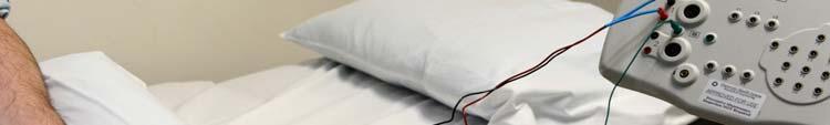
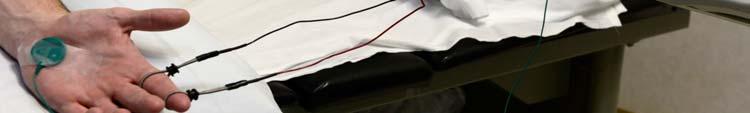
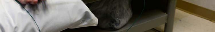
16 60 HZ INTERFERENCE E amp1 -E amp2 = 0 {For The Common Signal} Start With Electrode Lead Inspection All Three Electrodes Connected: Active/Reference/Ground All Electrodes Connected To The Proper Ports Continuity: No Breaks, Frayed/Loose Wires or Connectors (Gently Tug On Connector Both Ends) All Metal Electrode Interfaces Clean: No Rust, Old Caked-On Paste, Pitted Surfaces If 60 Hz Persists Go Ahead And Change Electrodes 60 HZ INTERFERENCE E amp1 -E amp2 = 0 {For The Common Signal} If 60 Hz Persists Go Ahead And Change Electrodes If 60 Hz Still Persists: Move Pre-Amp As Close As Possible To The Pt Intertwine The Electrode Leads & Bunch Them Up Next To The Patient With The Pre-Amp On Top Look For A Nearby Generator Source 16


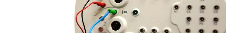

17 60 HZ INTERFERENCE E amp1 -E amp2 = 0 {For The Common Signal} If 60 Hz Persists Go Ahead And Change Electrodes If 60 Hz Still Persists: Move Pre-Amp As Close As Possible To The Pt Intertwine The Electrode Leads & Bunch Them Up Next To The Patient With The Pre-Amp On Top 60 HZ INTERFERENCE E amp1 -E amp2 = 0 {For The Common Signal} If 60 Hz Persists Go Ahead And Change Electrodes If 60 Hz Still Persists: Move Pre-Amp As Close As Possible To The Pt Intertwine The Electrode Leads & Bunch Them Up Next To The Patient With The Pre-Amp On Top 17


18 60 HZ INTERFERENCE E amp1 -E amp2 = 0 {For The Common Signal} If 60 Hz Persists Go Ahead And Change Electrodes If 60 Hz Still Persists: Move Pre-Amp As Close As Possible To The Pt Intertwine The Electrode Leads & Bunch Them Up Next To The Patient With The Pre-Amp On Top 60 HZ INTERFERENCE E amp1 -E amp2 = 0 {For The Common Signal} If 60 Hz Persists Go Ahead And Change Electrodes If 60 Hz Still Persists: Move Pre-Amp As Close As Possible To The Pt Intertwine The Electrode Leads & Bunch Them Up Next To The Patient With The Pre-Amp On Top 18


 19")
19 60 HZ INTERFERENCE E amp1 -E amp2 = 0 {For The Common Signal} If 60 Hz Persists Go Ahead And Change Electrodes If 60 Hz Still Persists: Move Pre-Amp As Close As Possible To The Pt Intertwine The Electrode Leads & Bunch Them Up Next To The Patient With The Pre-Amp On Top 60 HZ INTERFERENCE E amp1 -E amp2 = 0 {For The Common Signal} If 60 Hz Persists Start Turning Off Or UNPLUGGING Equipment Lights, Electric Appliances, Exam Table Heating Pads If In ICU: Bed, Calf Pump, Any Non-Essential Equip If 60 Hz Persists Touch The Patient With A Bit Of Paste On Finger NCV: Average Response With RR Not Divisible Into 60 (e.g. 3.3, 2.9, etc) 19
 EMG: Use Two Monopolar Needles Instead Of Surface Reference (May Need Needle Ground Too) With Reference Close to Insertion Site But Not Too Close To Active Deeper In Tissue If Using")
20 60 HZ INTERFERENCE E amp1 -E amp2 = 0 {For The Common Signal} If 60 Hz Persists Touch The Patient With A Bit Of Paste On Finger NCV: Average Response With RR Not Divisible Into 60 (e.g. 3.3, 2.9, etc) EMG: Use Two Monopolar Needles Instead Of Surface Reference (May Need Needle Ground Too) With Reference Close to Insertion Site But Not Too Close To Active Deeper In Tissue If Using Concentric: Switch To Two Monopolars 60 HZ INTERFERENCE E amp1 -E amp2 = 0 {For The Common Signal} If 60 Hz Persists If Using Concentric: Switch To Two Monopolars 20


21 60 HZ INTERFERENCE E amp1 -E amp2 = 0 {For The Common Signal} If 60 Hz Persists If Using Concentric: Switch To Two Monopolars 60 HZ INTERFERENCE E amp1 -E amp2 = 0 {For The Common Signal} Whenever 60 Hz Is Sufficient To Interfere With The Signal & The Ground Is Intact and Plugged In, Then The Active/Reference Electrodes Are Not Recording The Common Environmental Signals To The Same Degree Our Job Is To Do What It Takes To Make Them Record The Common Signals The Same 21
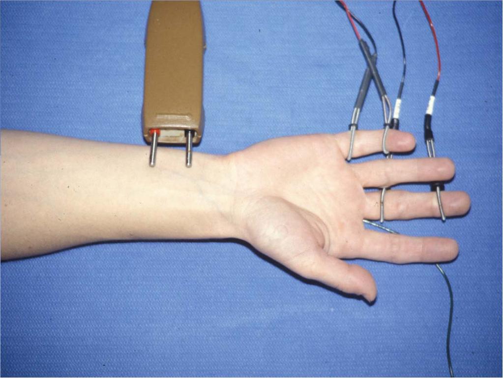
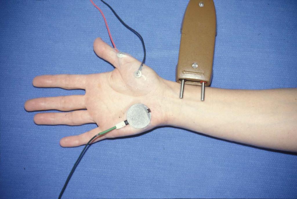
22 INTERELECTRODE SEPARATION AS IT PERTAINS TO DIFFERENTIAL AMPLIFICATION Why Not Put The Reference On The Big Toe And Forget About It? What Is The Deal With How Close Is Too Close And How Far Is Too Far INTERELECTRODE SEPARATION It Is Important To Consider The Separation Distance Between The Electrodes 22

23 SNAP INTERELECTRODE SEPARATION E-1/E-2: 4 cm Separation Maximize SNAP Amplitude Resolve SNAP Rise Time (~0.8 ms) NCV=D/T 50 M/s=D/0.8ms D=4 cm D<4cm SNAP Amp Not Maximized SNAP INTERELECTRODE SEPARATION E-/E-2: 4 cm Separation Maximize SNAP Amplitude Resolve SNAP Rise Time (~0.8 ms) 23

24 24


25 SNAP INTERELECTRODE SEPARATION When Using Bar Electrode For SNAPs Will Have A Smaller Amplitude Because Of Interelectrode Separation Think About Using Separate Disc Electrodes If Having Trouble Getting Response LFC Superfical Peroneal Sensory Sural Saphenous 25
26 PITFALL: AMPLITUDE 50-80% Amp Reduction; Normal Latency Axonal Loss/No Demyelination Pure Sensory Neuropathy/Ganglionopathy PITFALL: LATENCY 13% Latency Reduction; (Normal Latency) Miss Borderline Long Latency (False Neg) Could Miss A Borderline Neuropathy/CTS 26
27 INTERELECTRODE SEPARATION CMAP CMAP INTERELECTRODE SEPATION E-1: Muscle Motor Point E-2: Away From Muscle Tissue E-1/E-2 On Same Muscle Tissue Results In Reduced CMAP (Erroneously Conclude Axonal Loss, NMJ, or Myopathy) 27

28 28

29 PITFALL: AMPLITUDE ~50% Amplitude Reduction/Normal Latency Pure Axonal Loss Neurogenic/NMJ/Myopathy 29


30 FILTERS 30
31 FILTER A Device That Included Frequencies Of Interest But Excludes Unwanted Frequencies (Noise) FILTERS High Frequency: Low Pass Filter Low Frequency: High Pass Filter 31


32 FILTERS All Biologic Signals Can Be Conceptualized To Be Comprised Of Multiple Subcomponent Waveforms Of Varying Amplitude, Frequencies (High And Low), And Phases 32


33 LOW FREQUENCY FILTER Suppress Low Frequencies ( Hz) Affects Slowly Changing Portion Of Waveform 33
34 WHAT HAPPENS WHEN WE ELEVATE THE LOW FREQUENCY FILTERFROM 10 HZ TO 500 HZ? WAVEFORM COMPOSITION High Frequency Components: Fast Stuff Low Frequency Components: Slow Stuff When Elevate Low FF Affect Slow Stuff: YES Affect Fast Stuff: No So, What Happens To The Waveform s: Onset Lat, Peak Lat, Amp, Total Durat, Phases 34


35 ELEVATING LOW FREQUENCY FILTER Reduce Amplitude Peak Latency Shortens Negative Spike Duration Shortens Total Potential Duration Shortens Onset Latency Remains Unchanged Number Of Phases Increases 35


36 PITFALL: AMPLITUDE ~60% Amplitude Reduction/Normal Latency Sensory Axonal Neuropathy/Ganglionopathy LOW FREQUENCY FILTER EFFECTS CMAP 36
37 PITFALL: AMPLITUDE & PHASES ~80% Amplitude Reduction/Polyphasic Amp: Pure Axonal Neuropathy/Myopathy Phases: Asynchronous Demyelination GBS/Diabetes LOW FREQUENCY FILTER EFFECTS MUAP 37

38 PITFALL: AMPLITUDE & DURATION ~40% Amp Decline/50% Duration Shortening Could Create False + Myopathy HIGH FREQUENCY FILTER Suppresses High Frequencies ,000 Hz Affects The Fast Changing Portion Of The Waveform 38
39 WHAT HAPPENS WHEN YOU LOWER THE HIGH FREQUENCY FILTER? HIGH FREQUENCY FILTER Suppresses High Frequencies Affects Rapidly Changing Portions Of Waveform FAST STUFF VS SLOW STUFF Affects Fast Stuff Therefore What Would You Predict: Amp, Onset Latency, Negative Spike Duration, Total Waveform Duration 39


40 LOWERING HIGH FREQUENCY FILTER Reduces Waveform Amplitude Prolongs Peak Latency Prolongs Onset Latency Prolongs Negative Spike Duration Prolongs Total Waveform Duration Does Not Alter Number Of Phases 40
41 PITFALL: PEAK LATENCY ~15% Increase Peak Latency False Positive: Distal Focal/Generalized Neuropathy (CTS/Diabetes/etc.) STIMULATOR 41
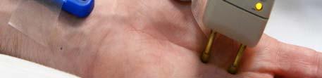
42 NERVE ACTIVATION CATHODE (-) ANODE (+) CATHODE NEGATIVE POLE (-) ATTRACTS CATIONS (+) DEPOLARIZES THE NERVE SUPRAMAXIMAL DEPOLARIZATION 20% > LARGEST CMAP SURFACE OR NEEDLE ELECTRODE 42

43 POSITIVE POLE ANODE ATTRACTS ANIONS (-) CAN DEPOLARIZE THE NERVE ANODAL BLOCK DOES NOT OCCUR LARGE SURFACE DISPERSIVE ELECTRODE WHEN USED WITH A NEEDLE CATHODE STIMULATOR 43


44 CURRENT FLOW HOW CATHODE STIMULATES 44
45 HOW THE ANODE STIMULATES ANODAL BLOCK Theoretically: Anode Hyperpolarizes Nerve And Blocks Action Potentials ANODE BLOCK DOES NOT OCCUR Rather: We Routinely Can Get Anodal Stimulation 45


46 HOW THE ANODE STIMULATES ANODAL STIMULATION PITFALL Anodal Stimulation: Shorten Latency 46
47 ANODAL STIMULATION PITFALL Anodal Stimulation: Shorten Latency ANODAL STIMULATION PITFALL Anodal Stimulation: Shorten Latency 47


48 ANODAL STIMULATION PITFALL Anodal Stimulation: Shorten Latency/Biphasic ANODAL STIMULATION PITFALL Anodal Stimulation: Shorten Latency/Biphasic 48


49 ANODAL STIMULATION PITFALL Anodal Stimulation: Shorten Latency/Biphasic ANODAL STIMULATION PITFALL Anodal Stimulation: Shorten Latency/Biphasic 49
50 ANODAL STIMULATION PITFALL: BLINK REFLEX Anodal Stimulation: Create Unanticipated Responses Mimicking False Pathways ANODAL STIMULATION PITFALL: BLINK REFLEX 50


51 ANODAL STIMULATION PITFALL: BLINK REFLEX ANODAL STIMULATION PITFALL: BLINK REFLEX 51

52 ANODAL STIMULATION PITFALL: BLINK REFLEX ANODAL STIMULATION PITFALL: BLINK REFLEX 52

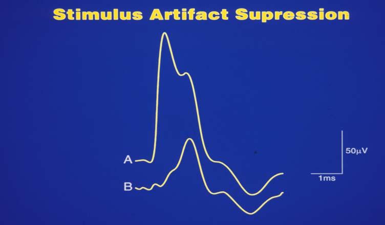
53 ANODAL STIMULATION PITFALL: BLINK REFLEX STIMULUS ARTIFACT 53


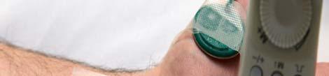
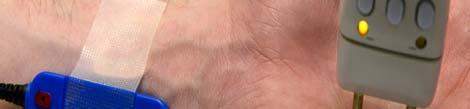
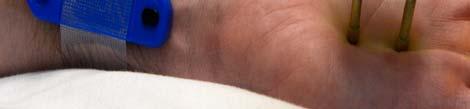
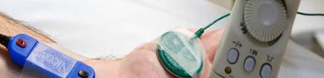
54 STIMULUS ARTIFACT Remove Excess Perspiration Remove Body Cream/Makeup Use Small Amount Electrolyte Paste Place Ground Next To E-1 Use Just Supramaximal Stimulus Reduce Skin Impedance Touch Patient Rotate Anode About Cathode Do Not Elevate LFF 54


55 STIMULUS ARTIFACT TOUCHING PATIENT 55

56 STIMULUS ARTIFACT MODULATION 56
DATA! NOW WHAT? Preparing your ERP data for analysis
 DATA! NOW WHAT? Preparing your ERP data for analysis Dennis L. Molfese, Ph.D. Caitlin M. Hudac, B.A. Developmental Brain Lab University of Nebraska-Lincoln 1 Agenda Pre-processing Preparing for analysis
PRODUCT SHEET TRANSDUCER MODULE GSR100C
 TRANSDUCER MODULE GSR100C The GSR100C electrodermal activity amplifier module is a single-channel, high-gain, differential amplifier designed to measure skin conductance via the constant voltage technique.
TASTEPROBE Type DTP-1. Pre-amplifier for recording from contact chemosensilla INSTRUCTIONS
 TASTEPROBE Type DTP-1 Pre-amplifier for recording from contact chemosensilla INSTRUCTIONS SYNTECH 2002 Hilversum, The Netherlands Reproduction of text and/or drawings is permitted for personal use. The
Pre-Processing of ERP Data. Peter J. Molfese, Ph.D. Yale University
 Pre-Processing of ERP Data Peter J. Molfese, Ph.D. Yale University Before Statistical Analyses, Pre-Process the ERP data Planning Analyses Waveform Tools Types of Tools Filter Segmentation Visual Review
PROGRAMMING GUIDE. Accurate Targeting. Precise Control.
 PROGRAMMING GUIDE Accurate Targeting. Precise Control. TABLE OF CONTENTS OVERVIEW Overview... 3 Linking a Remote Control to a Stimulator... 4 De-linking a Remote Control from a Stimulator... 4 Setting
PRODUCT SHEET
 ERS100C EVOKED RESPONSE AMPLIFIER MODULE The evoked response amplifier module (ERS100C) is a single channel, high gain, extremely low noise, differential input, biopotential amplifier designed to accurately
iworx Sample Lab Experiment AN-13: Crayfish Motor Nerve
 Experiment AN-13: Crayfish Motor Nerve Background The purpose of this experiment is to record the extracellular action potentials of crayfish motor axons. These spontaneously generated action potentials
VivoSense. User Manual Galvanic Skin Response (GSR) Analysis Module. VivoSense, Inc. Newport Beach, CA, USA Tel. (858) , Fax.
 Analysis Module. VivoSense, Inc. Newport Beach, CA, USA Tel. (858) , Fax.") VivoSense User Manual Galvanic Skin Response (GSR) Analysis VivoSense Version 3.1 VivoSense, Inc. Newport Beach, CA, USA Tel. (858) 876-8486, Fax. (248) 692-0980 Email: info@vivosense.com; Web: www.vivosense.com
VivoSense User Manual Galvanic Skin Response (GSR) Analysis VivoSense Version 3.1 VivoSense, Inc. Newport Beach, CA, USA Tel. (858) 876-8486, Fax. (248) 692-0980 Email: info@vivosense.com; Web: www.vivosense.com
Lesson 10 Manual Revision BIOPAC Systems, Inc.
 Physiology Lessons for use with the Lesson 10 ELECTROOCULOGRAM (EOG) I Eye Movement Saccades and Fixation during Reading Manual Revision 3.7.3 061808 Vertical J.C. Uyehara, Ph.D. Biologist BIOPAC Systems,
MEE 1000A. For more than 50 years, healthcare. Neuromaster MEE-1000A Intra-Operative Monitoring System
 IOM Data Acquisition System epilepsy monitoring electroencephalography ambulatory recording polysomnography icu/or monitoring electromyography ncv evoked potentials IOM MEE 000A Neuromaster MEE-000A Intra-Operative
J R Sky, Inc. Cross-Modulation Distortion Analyzer
 J R Sky, Inc. Cross-Modulation Distortion Analyzer J R Sky, Inc. 505 Evening Star Lane Bozeman, Montana 59715 USA Tel: +1.406-582-8154 email: nuoptix@jrsky.com web: www.jrsky.com revised: November 29,
The Venerable Triode. The earliest Triode was Lee De Forest's 1906 Audion.
 The Venerable Triode The very first gain device, the vacuum tube Triode, is still made after more than a hundred years, and while it has been largely replaced by other tubes and the many transistor types,
University of Utah Electrical & Computer Engineering Department ECE1050/1060 Oscilloscope
 University of Utah Electrical & Computer Engineering Department ECE1050/1060 Oscilloscope Name:, A. Stolp, 2/2/00 rev, 9/15/03 NOTE: This is a fill-in-the-blanks lab. No notebook is required. You are encouraged
DP1 DYNAMIC PROCESSOR MODULE OPERATING INSTRUCTIONS
 DP1 DYNAMIC PROCESSOR MODULE OPERATING INSTRUCTIONS and trouble-shooting guide LECTROSONICS, INC. Rio Rancho, NM INTRODUCTION The DP1 Dynamic Processor Module provides complete dynamic control of signals
ASK THE EXPERTS: Procedure for Verifying Magnetic Pickup Signal Integrity Using a Windrock Portable Analyzer
 December 2016 ASK THE EXPERTS: Procedure for Verifying Magnetic Pickup Signal Integrity Using a Windrock Portable Analyzer QUESTION: Does Windrock have some standard procedures for verifying magnetic pickup
EGM Einthoven Goldberger Module Type 701
 Operating Instructions for the PLUGSYS Module EGM Einthoven Goldberger Module Type 701 ECG amplifier for bipolar extremity leads after Einthoven and unipolar extremity leads after Goldberger (Version:
Electrical and Electronic Laboratory Faculty of Engineering Chulalongkorn University. Cathode-Ray Oscilloscope (CRO)
") 2141274 Electrical and Electronic Laboratory Faculty of Engineering Chulalongkorn University Cathode-Ray Oscilloscope (CRO) Objectives You will be able to use an oscilloscope to measure voltage, frequency
2141274 Electrical and Electronic Laboratory Faculty of Engineering Chulalongkorn University Cathode-Ray Oscilloscope (CRO) Objectives You will be able to use an oscilloscope to measure voltage, frequency
CHAPTER 3 OSCILLOSCOPES AND SIGNAL GENERATOR
 CHAPTER 3 OSCILLOSCOPES AND SIGNAL GENERATOR OSCILLOSCOPE 3.1 Introduction The cathode ray oscilloscope (CRO) provides a visual presentation of any waveform applied to the input terminal. The oscilloscope
BTV Tuesday 21 November 2006
 Test Review Test from last Thursday. Biggest sellers of converters are HD to composite. All of these monitors in the studio are composite.. Identify the only portion of the vertical blanking interval waveform
Bill of Materials: Super Simple Water Level Control PART NO
 Super Simple Water Level Control PART NO. 2169109 Design a simple water controller in which electrodes are required to sense high and low water levels in a tank. Whenever the water level falls below the
MEE 1000A. Neuromaster MEE-1000A. Intra-Operative Monitoring System
 IOM Data Acquisition System Neuromaster MEE-000A MEE 000A epilepsy monitoring electroencephalography ambulatory recording ICU/or monitoring polysomnography out of center sleep testing electromyography
SPECIAL SPECIFICATION 6911 Fiber Optic Video Data Transmission Equipment
 2004 Specifications CSJ 3256-02-079 & 3256-03-082 SPECIAL SPECIFICATION 6911 Fiber Optic Video Data Transmission Equipment 1. Description. Furnish and install Fiber Optic Video Data Transmission Equipment
Lecture 17 Microwave Tubes: Part I
 Basic Building Blocks of Microwave Engineering Prof. Amitabha Bhattacharya Department of Electronics and Communication Engineering Indian Institute of Technology, Kharagpur Lecture 17 Microwave Tubes:
USB-TG124A Tracking Generator User Manual
 USB-TG124A Tracking Generator User Manual Signal Hound USB-TG124A User Manual 2017, Signal Hound, Inc. 35707 NE 86th Ave La Center, WA 98629 USA Phone 360.263.5006 Fax 360.263.5007 This information is
EG4015. Digital Generator Governor Controller User Manual
 EG4015 Digital Generator Governor Controller User Manual Digital Governor for use in Gas and Diesel Generators with smoke and idle controls. Senses generator frequency, no magnetic pickup unit (MPU) is
Introduction: Overview. EECE 2510 Circuits and Signals: Biomedical Applications. ECG Circuit 2 Analog Filtering and A/D Conversion
 EECE 2510 Circuits and Signals: Biomedical Applications ECG Circuit 2 Analog Filtering and A/D Conversion Introduction: Now that you have your basic instrumentation amplifier circuit running, in Lab ECG1,
EPROM pattern generator with "Genlock"
 EPROM pattern generator with "Genlock" This generator uses an EPROM to store several pictures that can then be selected by means of a thumb-wheel switch. Alternatively, if the pictures stored are in a
4.9 BEAM BLANKING AND PULSING OPTIONS
 4.9 BEAM BLANKING AND PULSING OPTIONS Beam Blanker BNC DESCRIPTION OF BLANKER CONTROLS Beam Blanker assembly Electron Gun Controls Blanker BNC: An input BNC on one of the 1⅓ CF flanges on the Flange Multiplexer
SPECIAL SPECIFICATION 1291 Fiber Optic Video Data Transmission Equipment
 1993 Specifications CSJ 0500-01-117 SPECIAL SPECIFICATION 1291 Fiber Optic Video Data Transmission Equipment 1. Description. This Item shall govern for the furnishing and installation of Fiber Optic Video
CM-1UTP CAMERA MASTER UTP ADAPTOR
 CM-1UTP CAMERA MASTER UTP ADAPTOR INSTRUCTION BOOK CM-1UTP.ISB TABLE OF CONTENTS FORWARD 2 VIDEO STANDARDS 2 COAXIAL CABLE vs UTP WIRE CABLE 3 MEASUREMENT 3 MOUNTING THE CM1-UTP ADAPTOR 3 UTP WIRE CABLE
The Distortion Magnifier
 The Distortion Magnifier Bob Cordell January 13, 2008 Updated March 20, 2009 The Distortion magnifier described here provides ways of measuring very low levels of THD and IM distortions. These techniques
UNIT-3 Part A. 2. What is radio sonde? [ N/D-16]
![UNIT-3 Part A. 2. What is radio sonde? [ N/D-16]](/thumbs/88/116973079.jpg "UNIT-3 Part A. 2. What is radio sonde? [ N/D-16]") UNIT-3 Part A 1. What is CFAR loss? [ N/D-16] Constant false alarm rate (CFAR) is a property of threshold or gain control devices that maintain an approximately constant rate of false target detections
UNIT-3 Part A 1. What is CFAR loss? [ N/D-16] Constant false alarm rate (CFAR) is a property of threshold or gain control devices that maintain an approximately constant rate of false target detections
User Guide Slow Cortical Potentials (SCP)
") User Guide Slow Cortical Potentials (SCP) This user guide has been created to educate and inform the reader about the SCP neurofeedback training protocol for the NeXus 10 and NeXus-32 systems with the
User Guide Slow Cortical Potentials (SCP) This user guide has been created to educate and inform the reader about the SCP neurofeedback training protocol for the NeXus 10 and NeXus-32 systems with the
SPECIFICATIONS FOR TENDER # A SUPPLY OF ONE COMBINATION EMG/NCS/EP AND EEG SYSTEM FOR WESTERN HEALTH
 SPECIFICATIONS FOR TENDER #0171-0819A SUPPLY OF ONE COMBINATION EMG/NCS/EP AND EEG SYSTEM FOR WESTERN HEALTH CLOSING DATE: 3 March 2008 CLOSING TIME: 11:00 AM (Newfoundland Time) Invitation to Tender for
SPECIAL SPECIFICATION 6735 Video Optical Transceiver
 2004 Specifications CSJ 0924-06-244 SPECIAL SPECIFICATION 6735 Video Optical Transceiver 1. Description. This Item governs the furnishing and installation of Video optical transceiver (VOTR) in field location(s)
Using an oscilloscope - The Hameg 203-6
 Using an oscilloscope - The Hameg 203-6 What does an oscilloscope do? Setting up How does an oscilloscope work? Other oscilloscope controls Connecting a function generator Microphones audio signals and
1995 Metric CSJ SPECIAL SPECIFICATION ITEM 6031 SINGLE MODE FIBER OPTIC VIDEO TRANSMISSION EQUIPMENT
 1995 Metric CSJ 0508-01-258 SPECIAL SPECIFICATION ITEM 6031 SINGLE MODE FIBER OPTIC VIDEO TRANSMISSION EQUIPMENT 1.0 Description This Item shall govern for the furnishing and installation of color Single
Advanced Test Equipment Rentals ATEC (2832)
") Established 1981 Advanced Test Equipment Rentals www.atecorp.com 800-404-ATEC (2832) This product is no longer carried in our catalog. AFG 2020 Characteristics Features Ordering Information Characteristics
Established 1981 Advanced Test Equipment Rentals www.atecorp.com 800-404-ATEC (2832) This product is no longer carried in our catalog. AFG 2020 Characteristics Features Ordering Information Characteristics
Build A Video Switcher
 Build A Video Switcher VIDEOSISTEMAS serviciotecnico@videosistemas.com www.videosistemas.com Reprinted with permission from Electronics Now Magazine September 1997 issue Copyright Gernsback Publications,
EP/EMG Measuring System MEB-9200J/K
 EP/EMG Measuring System MEB-9200J/K Quick Examination User friendly operation menu You can arrange the settings of the Quick menu window according to your own operation procedure. You can directly open
Svetlana 3CX10,000A7/8160
 Svetlana 3CX1,A7/816 High-Mu Power Triode T he Svetlana 3CX1,A7/816 is a high-performance ceramic/metal power triode designed for use in zero-bias, class B RF or audio amplifiers. A modern mesh filament
1993 Specifications CSJ , etc. SPECIAL SPECIFICATION ITEM CCTV Central Equipment
 1993 Specifications CSJ 0922-33-042, etc. SPECIAL SPECIFICATION ITEM 8549 CCTV Central Equipment 1. Description. This Item shall govern for the furnishing and installation of closed circuit television
Spectrum Analyser Basics
 Hands-On Learning Spectrum Analyser Basics Peter D. Hiscocks Syscomp Electronic Design Limited Email: phiscock@ee.ryerson.ca June 28, 2014 Introduction Figure 1: GUI Startup Screen In a previous exercise,
New Generation of MEA-Systems: MEA2100-System
 New Generation of MEA-Systems: MEA2100-System Integrated stimulation Gain and bandwidth adjustable via software Up to 240 recording channels Variable contact unit for microelectrode arrays with 32, 60
Experiment 9A: Magnetism/The Oscilloscope
 Experiment 9A: Magnetism/The Oscilloscope (This lab s "write up" is integrated into the answer sheet. You don't need to attach a separate one.) Part I: Magnetism and Coils A. Obtain a neodymium magnet
PRACTICAL APPLICATIONS OF ELECTRONICS IN ANAESTHESIA. G. A. HAY Department of Medical Physics, University of Leeds
 Brit. J. Anaesth. (1955), 27, 622 PRACTICAL APPLICATIONS OF ELECTRONICS IN ANAESTHESIA 1 BY G. A. HAY Department of Medical Physics, University of Leeds PART I: BASIC PRINCIPLES IN the last twenty years
V 180 Series Photoelectric Switches
 D A T A S H E E T V 180 Series Photoelectric Switches VS 180 / VE 180 1 m x VL 180 m 1 m*) *) with polarizing filter v VT 180 110 mm 00 mm n Photoelectric switches of cylindrical design in threaded metal
SPECIAL SPECIFICATION 1987 Single Mode Fiber Optic Video Transmission Equipment
 1993 Specifications CSJ 0027-12-086, etc. SPECIAL SPECIFICATION 1987 Single Mode Fiber Optic Video Transmission Equipment 1. Description. This Item shall govern for the furnishing and installation of color
- 1 - Programmable Gain Amplifier PGA Manual
 - 1 - Programmable Gain Amplifier PGA Manual Imprint Information in this document is subject to change without notice. No part of this document may be reproduced or transmitted without the express written
Understanding Layered Noise Reduction
 Technology White Paper Understanding Layered Noise Reduction An advanced adaptive feature used in the Digital-ONE NR, Digital-ONE NR+ and intune amplifiers from IntriCon. Updated September 13, 2005 Layered
Specifications. End-Point Linearity - ±5% F.S., when used with HACO SCR-speed control
 Specifications Model 552 Catalog No. Model Power 55-0665 552 115 VAC, 50-60 Hz 55-0673 552A 230 VAC, 50-60 Hz Input - Single-ended, DC coupled 0 to +10V. Signal source can be Floating (not referenced to
The Cathode Ray Tube
 Lesson 2 The Cathode Ray Tube The Cathode Ray Oscilloscope Cathode Ray Oscilloscope Controls Uses of C.R.O. Electric Flux Electric Flux Through a Sphere Gauss s Law The Cathode Ray Tube Example 7 on an
HBI Database. Version 2 (User Manual)
") HBI Database Version 2 (User Manual) St-Petersburg, Russia 2007 2 1. INTRODUCTION...3 2. RECORDING CONDITIONS...6 2.1. EYE OPENED AND EYE CLOSED CONDITION....6 2.2. VISUAL CONTINUOUS PERFORMANCE TASK...6
HBI Database Version 2 (User Manual) St-Petersburg, Russia 2007 2 1. INTRODUCTION...3 2. RECORDING CONDITIONS...6 2.1. EYE OPENED AND EYE CLOSED CONDITION....6 2.2. VISUAL CONTINUOUS PERFORMANCE TASK...6
CATHODE-RAY OSCILLOSCOPE (CRO)
") CATHODE-RAY OSCILLOSCOPE (CRO) I N T R O D U C T I O N : The cathode-ray oscilloscope (CRO) is a multipurpose display instrument used for the observation, measurement, and analysis of waveforms by plotting
CATHODE-RAY OSCILLOSCOPE (CRO) I N T R O D U C T I O N : The cathode-ray oscilloscope (CRO) is a multipurpose display instrument used for the observation, measurement, and analysis of waveforms by plotting
C-net WIND. User s Guide
 C-net WIND User s Guide EMC Directive 89/336/EEC This product has been designed to be compliant with the above EMC Directive. Maximum performance and compliance with the EMC Directive can only be ensured
ECG Demonstration Board
 ECG Demonstration Board Fall 2012 Sponsored By: Texas Instruments Design Team : Matt Affeldt, Alex Volinski, Derek Brower, Phil Jaworski, Jung-Chun Lu Michigan State University Introduction: ECG boards
RICHLAND COLLEGE School of Engineering Business & Technology Rev. 0 W. Slonecker Rev. 1 (8/26/2012) J. Bradbury
 J. Bradbury") RICHLAND COLLEGE School of Engineering Business & Technology Rev. 0 W. Slonecker Rev. 1 (8/26/2012) J. Bradbury INTC 1307 Instrumentation Test Equipment Teaching Unit 8 Oscilloscopes Unit 8: Oscilloscopes
RICHLAND COLLEGE School of Engineering Business & Technology Rev. 0 W. Slonecker Rev. 1 (8/26/2012) J. Bradbury INTC 1307 Instrumentation Test Equipment Teaching Unit 8 Oscilloscopes Unit 8: Oscilloscopes
ECE 5765 Modern Communication Fall 2005, UMD Experiment 10: PRBS Messages, Eye Patterns & Noise Simulation using PRBS
 ECE 5765 Modern Communication Fall 2005, UMD Experiment 10: PRBS Messages, Eye Patterns & Noise Simulation using PRBS modules basic: SEQUENCE GENERATOR, TUNEABLE LPF, ADDER, BUFFER AMPLIFIER extra basic:
Windows AEP & IHP Protocol
 Windows AEP & IHP Protocol Martyn Hyde Kris Madsen Jill Witte Mount Sinai Hospital, Toronto mhyde@mtsinai.on.ca 1 Agenda Updated Assessment Protocol Major system errors AD Dx issues Click artifact 60 Hz
ISCEV SINGLE CHANNEL ERG PROTOCOL DESIGN
 ISCEV SINGLE CHANNEL ERG PROTOCOL DESIGN This spreadsheet has been created to help design a protocol before actually entering the parameters into the Espion software. It details all the protocol parameters
PAST EXAM PAPER & MEMO N3 ABOUT THE QUESTION PAPERS:
 EKURHULENI TECH COLLEGE. No. 3 Mogale Square, Krugersdorp. Website: www. ekurhulenitech.co.za Email: info@ekurhulenitech.co.za TEL: 011 040 7343 CELL: 073 770 3028/060 715 4529 PAST EXAM PAPER & MEMO N3
16 Stage Bi-Directional LED Sequencer
 16 Stage Bi-Directional LED Sequencer The bi-directional sequencer uses a 4 bit binary up/down counter (CD4516) and two "1 of 8 line decoders" (74HC138 or 74HCT138) to generate the popular "Night Rider"
ECE 402L APPLICATIONS OF ANALOG INTEGRATED CIRCUITS SPRING No labs meet this week. Course introduction & lab safety
 ECE 402L APPLICATIONS OF ANALOG INTEGRATED CIRCUITS SPRING 2018 Week of Jan. 8 Jan. 15 Jan. 22 Jan. 29 Feb. 5 Feb. 12 Feb. 19 Feb. 26 Mar. 5 & 12 Mar. 19 Mar. 26 Apr. 2 Apr. 9 Apr. 16 Apr. 23 Topic No
The Bio Tuner Model BT8 Manual
 The Bio Tuner Model BT8 Manual CONTENTS WELCOME TO SOTA... 2 BEFORE USING... 2 LEARN MORE... 2 COMPLETE UNIT INCLUDES... 2 DO NOT USE... 3 CAUTIONS... 3 SUMMARY OF LIGHTS... 4 HOW TO USE THE BIO TUNER...
Pole Zero Correction using OBSPY and PSN Data
 Pole Zero Correction using OBSPY and PSN Data Obspy provides the possibility of instrument response correction. WinSDR and WinQuake already have capability to embed the required information into the event
TOUR SERIES LOUDSPEAKER SYSTEMS
 TOUR SERIES LOUDSPEAKER SYSTEMS From Fender Pro Audio Owner's Manual for 2912(c), 2915(c) P/N 050757 Fender Musical Instruments 7975 North Hayden Road, Scottsdale, Arizona 85258 U.S.A. Fender knows the
RoHS. Atma-Sphere Music Preamplifier. model P-2 OWNER'S MANUAL. Please study this document carefully before using equipment
 1742 Selby Av. St. Paul, MN 55104 651 690 2246 atma sphere.com Atma-Sphere Music Preamplifier model P-2 OWNER'S MANUAL Please study this document carefully before using equipment RoHS CONGRATULATIONS!
User Guide EMG. This user guide has been created to educate and inform the reader about doing EMG measurements
 User Guide EMG This user guide has been created to educate and inform the reader about doing EMG measurements For more information about NeXus, our BioTrace+ software, please visit our website or contact
Development of Simple-Matrix LCD Module for Motion Picture
 Development of Simple-Matrix LCD Module for Motion Picture Kunihiko Yamamoto* Shinya Takahashi* Kouki Taniguchi* * A1203 Project Team Abstract A simple-matrix LCD module (12.1-in. SVGA) has been developed
INSTRUCTION MANUAL COMMANDER BDH MIG
 INSTRUCTION MANUAL COMMANDER BDH MIG Valid from 0327 50173001A Version 1.0 CONTENTS INTRODUCTION... 0-1 1. PRIMARY OPERATIONAL FUNCTIONS... 1-1 Reading and setting... 1-1 Programmes... 1-2 Trigger function...
Why Engineers Ignore Cable Loss
 Why Engineers Ignore Cable Loss By Brig Asay, Agilent Technologies Companies spend large amounts of money on test and measurement equipment. One of the largest purchases for high speed designers is a real
Plessey PS EPIC 6:2 Multiplex box Instruction Manual.
 Plessey PS25006 - EPIC 6:2 Multiplex box Instruction Manual. Standard Components PS25006 One PS25006 EPIC 6 input, 2 output multiplex box unit. User Guide Contents 1.0 Introduction Page 2 2.0 The PS25006
N3ZI Digital Dial Manual For kit with Backlit LCD Rev 4.00 Jan 2013 PCB
 N3ZI Digital Dial Manual For kit with Backlit LCD Rev 4.00 Jan 2013 PCB Kit Components Item Qty Designator Part Color/Marking PCB 1 LCD Display 1 LCD 1602 Volt Regulator 1 U1 78L05, Black TO-92 Prescaler
OTM-3550-SW FREQUENCY AGILE F.C.C. COMPATIBLE TELEVISION MODULATOR INSTRUCTION MANUAL
 FREQUENCY AGILE F.C.C. COMPATIBLE TELEVISION MODULATOR INSTRUCTION MANUAL Phone: (209) 586-1022 (800) 545-1022 Fax: (209) 586-1026 E-Mail: salessupport@olsontech.com 025-000233 REV E www.olsontech.com
BER MEASUREMENT IN THE NOISY CHANNEL
 BER MEASUREMENT IN THE NOISY CHANNEL PREPARATION... 2 overview... 2 the basic system... 3 a more detailed description... 4 theoretical predictions... 5 EXPERIMENT... 6 the ERROR COUNTING UTILITIES module...
Burlington County College INSTRUCTION GUIDE. for the. Hewlett Packard. FUNCTION GENERATOR Model #33120A. and. Tektronix
 v1.2 Burlington County College INSTRUCTION GUIDE for the Hewlett Packard FUNCTION GENERATOR Model #33120A and Tektronix OSCILLOSCOPE Model #MSO2004B Summer 2014 Pg. 2 Scope-Gen Handout_pgs1-8_v1.2_SU14.doc
University of Utah Electrical Engineering Department EE1050/1060 Oscilloscope. Name:, Lab TA:
 University of Utah Electrical Engineering Department EE1050/1060 Oscilloscope Name:, Lab TA: A. Stolp, 2/2/00 rev, 9/14/00 NOTE: This is a fill-in-the-blanks lab. No notebook is required. You are encouraged
Supplemental Material for Gamma-band Synchronization in the Macaque Hippocampus and Memory Formation
 Supplemental Material for Gamma-band Synchronization in the Macaque Hippocampus and Memory Formation Michael J. Jutras, Pascal Fries, Elizabeth A. Buffalo * *To whom correspondence should be addressed.
User Guide. qeeg NeXus-32. This user guide has been created to educate and inform the reader about doing qeeg measurements with the NeXus-32
 User Guide qeeg NeXus-32 This user guide has been created to educate and inform the reader about doing qeeg measurements with the NeXus-32 For more information about NeXus, our BioTrace+ software, please
Exercise 1: Muscles in Face used for Smiling and Frowning Aim: To study the EMG activity in muscles of the face that work to smile or frown.
 Experiment HP-9: Facial Electromyograms (EMG) and Emotion Exercise 1: Muscles in Face used for Smiling and Frowning Aim: To study the EMG activity in muscles of the face that work to smile or frown. Procedure
MODIFYING A SMALL 12V OPEN FRAME INDUSTRIAL VIDEO MONITOR TO BECOME A 525/625 & 405 LINE MULTI - STANDARD MAINS POWERED UNIT. H. Holden. (Dec.
 MODIFYING A SMALL 12V OPEN FRAME INDUSTRIAL VIDEO MONITOR TO BECOME A 525/625 & 405 LINE MULTI - STANDARD MAINS POWERED UNIT. H. Holden. (Dec. 2017) INTRODUCTION: Small open frame video monitors were made
MATRIX. 24Bit /192kHz ASRC Stereo Audio Processor MATRIX. 2-Channel 24-bit 192-kHz ASRC Desktop Digital Audio Processor CUBE.
 24Bit /192kHz ASRC Stereo Audio Processor 2-Channel 24-bit 192-kHz ASRC Desktop Digital Audio Processor User Guide CUBE Thank you for purchasing digital audio processor! This manual booklet provides you
Portable in vivo Recording System
 Portable in vivo Recording System 16 or 32 channel version Pre- and filter amplifier included USB 2.0 data transfer Adapters for commercially available probes Real-time signal detection and feedback Flexible
SPECIAL REPORT OF THE SUBCOMMITTEE ON POLARITY STANDARDS 1
 This document has been converted from the original publication: Thigpen, Ben B., Dalby, A. E. and Landrum, Ralph, 1975, Report on Subcommittee on Polarity Standards *: Geophysics, 40, no. 04, 694-699.
Metal Electrode Meter
 Metal Electrode Meter INSTRUCTION MANUAL FOR Metal Electrode Meter MODEL 2900 Serial # Date PO Box 850 Carlsborg, WA 98324 U.S.A. 360-683-8300 800-426-1306 FAX: 360-683-3525 http://www.a-msystems.com Version
OPERATING INSTRUCTIONS FOR SYLVANIA. Type I08 Cathode-Ray Oscilloscope. Sylvania Electric Products Inc. Industrial Apparatus. Emporium, Pennsylvania
 OPERATING INSTRUCTIONS FOR SYLVANIA Type I08 Cathode-Ray Oscilloscope Sylvania Electric Products Inc. Industrial Apparatus Plant Emporium, Pennsylvania OPERATING INSTRUCTIONS FOR Sylvania Type 08 Cathode-Ray
Application Note AN-LD09 Rev. B Troubleshooting Low Noise Systems. April, 2015 Page 1 NOISE MEASUREMENT SYSTEM BASELINES INTRODUCTION
 Troubleshooting Low Noise Systems April, 2015 Page 1 INTRODUCTION The exceedingly low level of electronic noise produced by the QCL family of drivers makes narrower linewidths and stable center wavelengths
Noise Detector ND-1 Operating Manual
 Noise Detector ND-1 Operating Manual SPECTRADYNAMICS, INC 1849 Cherry St. Unit 2 Louisville, CO 80027 Phone: (303) 665-1852 Fax: (303) 604-6088 Table of Contents ND-1 Description...... 3 Safety and Preparation
Feedback: Part A - Basics
 Feedback: Part A - Basics Slides taken from: A.R. Hambley, Electronics, Prentice Hall, 2/e, 2000 1 Overview The Concept of Feedback Effects of feedback on Gain Effects of feedback on non linear distortion
PESIT Bangalore South Campus
 SOLUTIONS TO INTERNAL ASSESSMENT TEST 3 Date : 8/11/2016 Max Marks: 40 Subject & Code : Analog and Digital Electronics (15CS32) Section: III A and B Name of faculty: Deepti.C Time : 11:30 am-1:00 pm Note:
Owner s Manual PRE1. v1.2. Triode Class A Line Preamplifier
 Owner s Manual PRE1 Triode Class A Line Preamplifier www.lab12.gr v1.2 Table of Contents It is yours Features Installation & Placement Front Panel Rear Panel Remote Control Main connections For the safety
SIMET AVIKO D INSTRUCTION MANUAL SORTING Solutions, Ltd.
 SIMET AVIKO D INSTRUCTION MANUAL 1870 SORTING Solutions, Ltd. 1. TABLE OF CONTENTS 1. TABLE OF CONTENTS...1 2. INTRODUCTION...2 2.1. Application...2 2.2. Operating Conditions...2 2.3. Electro - Optical
Diamond Cut Productions / Application Notes AN-2
 Diamond Cut Productions / Application Notes AN-2 Using DC5 or Live5 Forensics to Measure Sound Card Performance without External Test Equipment Diamond Cuts DC5 and Live5 Forensics offers a broad suite
TEKTRONIX 2465B OSCILLOSCOPE: MAIN BOARD INTER-TRACK LEAKAGE.
 TEKTRONIX 2465B OSCILLOSCOPE: MAIN BOARD INTER-TRACK LEAKAGE. Dr. H. Holden. June 2014. This article describes a complex fault which developed in one of my three Tektronix 2465B oscilloscopes. I decided
SAFETY INFORMATION. 7. Do not force switched or external connections in any way. They should all connect easily, without needing to be forced.
 SAFETY INFORMATION 1. To ensure the best results from this product, please read this manual and all other documentation before operating your equipment. Retain all documentation for future reference. 2.
CHAPTER 3 SEPARATION OF CONDUCTED EMI
 54 CHAPTER 3 SEPARATION OF CONDUCTED EMI The basic principle of noise separator is described in this chapter. The construction of the hardware and its actual performance are reported. This chapter proposes
XO-231 USER S MANUAL. Crossover ENGLISH
 XO-231 Crossover ENGLISH USER S MANUAL IMPORTANT SAFETY INSTRUCTIONS For your own safety you should read this section in full first! Risk of electrical shock! Connect the device only to a properly wired
TELEPHONE HYBRID-2 USER MANUAL. hybrid-2 manual page 1. Version 1.04 (smd)
") TELEPHONE HYBRID-2 USER MANUAL Version 1.04 (smd) hybrid-2 manual page 1 Dear Customer, Thank you for choosing the Telephone Hybrid-2. This time you are not faced with a huge manual because it is simply
TELEPHONE HYBRID-2 USER MANUAL Version 1.04 (smd) hybrid-2 manual page 1 Dear Customer, Thank you for choosing the Telephone Hybrid-2. This time you are not faced with a huge manual because it is simply
THE OPERATION OF A CATHODE RAY TUBE
 THE OPERATION OF A CATHODE RAY TUBE OBJECT: To acquaint the student with the operation of a cathode ray tube, and to study the effect of varying potential differences on accelerated electrons. THEORY:
Laboratory Safety. Physiological Effects of Electricity. by Rodger Ziemer, UCCS ECE Department
 Laboratory Safety by Rodger Ziemer, UCCS ECE Department Physiological Effects of Electricity Shocks Involving 60 Hz, Sinusoidal Voltages 1. Effects of 60 Hz sinusoidal voltages are related to the rms value