Spectral Multiband Resonator from 4ms Company Eurorack Module User Manual v1.1 (firmware v5: December 2016)
|
|
|
- Ralph Fleming
- 5 years ago
- Views:
Transcription
1 Spectral Multiband Resonator from 4ms Company Eurorack Module User Manual v1.1 (firmware v5: December 2016) The Spectral Multiband Resonator from 4ms Company is a versatile resonant filter with six bandpass resonators/filters having variable frequency (quantized to scales and/or 1V/oct tracked), and variable Q/resonance. Stereo inputs/outputs and a host of unique features allows for many uses: Create beautiful moving chord structures, quantized to selectable scales Process audio like a classic filter bank/eq Pluck/ping/strike to ring like a marimba, gong, or membrane Beat-sync to an audio track, triggering modular sounds in sync with original audio Vocode, outputting spectral data to a second SMR Re-mix tracks Harmonize to audio Quantize audio to built-in or custom programmed scales New in version 5: Control up to 6 external VCOs with 1V/oct CV, for sequences, chords, and melodies Transposition and fine tuning allows the SMR to be quickly tuned to external equipment Forbidden Notes feature lets you select notes that will be skipped when rotating or spreading Two-pass resonant filter for lusher tones and tighter filtering of the input signal New major and minor scale banks...and much more! Check 4msCompany.com for updates to the manual
2 Basic features: Six resonator/filter channels Variable "Q" (Resonance) ranges from classic band-pass to highly resonant ringing New in v5: Second resonator can be faded in for additional Q (see page 13) Ring of 20 full-color lights displays the channel frequency Channel frequencies move about the scale using Rotation and Spread Rotation "spins" the frequencies around the scale Spread controls the gap between neighboring bands Morph creates a variable speed cross-fade when the channels are rotated or spread Lock buttons prevent each channel from changing in frequency (resonance can also be locked) Freq Nudge knobs create de-tuning effects, or are useful for picking out a precise frequency Frequency CV input (1V/octave) for even and odd bands (flip switch selects single or multiple channel control) Adjustable tracking compensation and offset Stereo inputs and outputs stagger the bands into evens/odds for an immersive stereo field Spectral content outputs for each channel (Env Out jacks) allow for vocoding (spectral transfer) Switch selects Fast or Slow tracking speeds, or trigger outputs Trigger output mode fires a trigger when envelope crosses a threshold: useful for extracting a beat from music New in v5: Trigger threshold level can be saved independently of channel audio level (see page 18) New in v5: 1V/Oct outputs for each channel for using the SMR as a sequencer or chord machine with external VCOs Glissando (glide) can be enabled (see page 18) Sliders and CV jacks control each filter's level Slew switch applies slew-limiting to the CV level jacks, which prevents clicking from clocks or triggers Each bank has 11 scales of 20 frequencies/notes each Scale banks for Major and Minor scales and chords (new in v5), Western intervals and triads, Penatonic scales, Shrutis (India), Chromatic, Diatonic, Micro-tonal 17-note/octave, Mesopotamian, Gamelan (Pelog and Slendro), Bohlen-Pierce 13-note tritave, Wendy Carlos's Alpha and Gamma scales. Equal temperament and Just Intonation tunings (see back page) Rotation/Spread moves about an entire bank, or can be limited to a single scale New in v5: Each channel can be fine-tuned by cents and/or transposed by a whole number of semitones (p ) New in v5: Specific notes on the light ring can be forbidden, blocking out certain frequencies (see page 16) White noise is normalized to the inputs, so the SMR can be used without an external signal Settings and LED color scheme can be saved and recalled in multiple banks Controls and jacks: 2 Filter channel level sliders Six sliders set the level of each filter White light on each slider indicates filter level (flashes for clipping) Six CV inputs for level of each filter. (0 to +5V). Slider attenuates CV on jack Twenty full-color LEDs indicate which filters are assigned to which channel Colors on light ring match colors of Env Out lights Brightness of each light shows level of each filter Resonance (Q) Res (Q) CV jack (0 to +5V) Knob (offsets CV jack) Stereo input and output (divided into even/odd bands) Odd input jack and Even output jack serve as Mono in/out Clipping LED between IN jacks flickers when input is clipping (about 19.2Vpp or +/-9.6V) Rotation shifts frequency pattern up or down Rotate Clockwise trigger input (2V threshold) Rotate Counter-clockwise trigger input (2V threshold) Rotate CV jack maps any waveshape to a rotation pattern (0 to +5V) Spread sets the interval (spacing) between channels Spread CV input jack (0 to +10V) Knob (offsets CV value) Morph sets speed of cross fading rotating, spreading, or scale selection Morph CV input jack (0 to +10V) Knob (offsets CV jack) Scale CV input jack selects scale from current bank (0 to +5V) Six Env Out jacks: CV outputs that follow envelope of frequency content per band (0 to +8V output) Fast Slow switch selects envelope tracking speed, or Trigger output mode Pre/Post switch selects whether Env Out jacks track the filter before or after the slider attenuates New in v5: Holding down ROTATE while flipping to Fast enables 1V/octave outputs on Env Out jacks (see p. 18) Six Lock buttons lock the frequency of each channel Button is lit when locked Rotation, Spread, Freq Nudge, Scale, and Bank will not change when locked Turning Q knob while holding a lock button also locks the Q value (button flashes to indicate Q-lock) Lock jack: locks/unlocks even or odd channels when triggered (2V threshold) Freq jacks: 1V/oct frequency input jacks for even and odd channels (10 octave range, 0 to +10V) switch selects if Freq jack, Freq Nudge knob, and Lock jack control all odd channels (1/3/5) or just channel switch selects if Freq jack, Freq Nudge knob, and Lock jack control all even channels (2/4/6) or just channel 6


3 Slew switch enables slew-limiting of incoming CV on the level CV jacks (click and pop prevention) Amount of slew limiting is proportional to Morph setting at the time the switch is flipped on. Scale Rotation switch enables channels to rotate into the next/previous scale each time they rotate fully around Note: The active voltage range for each jack is given. All jacks are tolerant of signals from -12V to +12V, but signals outside the active range are clipped to the active range. For example, on a jack with an active range of 0 to +5V, a voltage of -4V is seen by the SMR as 0V, and +8V is seen as +5V. Advanced features: Program your own scale: The frequency of each of the 20 notes can be assigned by setting the octave, the semi-tone, and micro-tone Up to 11 scales can be saved permanently in the user bank Adjust color scheme of the lights: Pick a pre-programmed color scheme or create your own using the sliders to set red/green/blue values. Custom color schemes can be saved permanently Save your settings in one of six Settings Slots. Note position, scale/bank selection, Q value, lock settings and color scheme can be saved and recalled on the fly. On startup, the SMR loads settings from the last saved bank. Optional alternative filter type (BpRe filter) More exponential decay and different timbral qualities when plucked. Freq jacks no longer track 1V/oct in this mode New in v5: Adjust the 1V/oct tracking for 1V/oct outputs, in order to compensate for external VCOs that may track slightly more or less than 1.00V/octave (see page 20) New in v5: Two-Pass resonant filter essentially acts like two SMRs in series. Original one-pass mode can be selected in system mode. Two-Pass is the default. (see page 21) New in v5: Channels may be transposed in half-step degrees, from -6 semitones to +6 semitones. Each channel can have its own transposition, or all channels in an even/odd group can be transposed together (see page 12) New in v5: Channels may be fine-tuned with exponential tuning in order to tune and track with external 1V/octave equipment (see page 11) New in v5: Up to 14 notes can be Forbidden, meaning the SMR will not rotate or spread any channel onto that note position. (see page 16) Slider LEDs can be selected to display clipping and level, or just level Adjust tracking compensation and offset for the Freq jacks Firmware can be updated by playing encoded audio files from a computer into the SMR Specifications 26 HP Eurorack format module 16-to-16pin eurorack power cable (included) 0.95 (24mm) maximum depth Power consumption: +12V rail: 86mA max (jumper set to 5V) 110mA max (jumper set to 12V) -12V rail: 28mA max +5V rail: 25mA (jumper set to 5V) 0mA (not used when jumper set to 12V) Jumper Most modern modular power supplies provide power on the +5V rail. It's recommended to use the +5V rail when available. If your system does not provide +5V, or if your +5V rail is noisy, the SMR can be set to generate an internal 5V from the +12V rail by moving the jumper to +12V as shown above. VSEL jumper: +5V VSEL jumper: +12V 3
4 Getting started: your first patch TO MIXER The easiest SMR patch is making droning chords. Only one cable is needed! Set up the SMR as shown: Turn all the Lock buttons off (press any button that's lit to turn it off) Flip Scale Rotation switch off (down) Freq Nudge to 0% (both knobs, in the upper left and upper right) Res (Q) knob to between 50% and 100% Spread to 0% Morph to about 50% Patch the black OUT jack into your mixer (unpatch all other jacks). Turn RES (Q) to 100% There are six sliders. Each one controls the volume of a filter/resonator channel. Push down all six sliders, then slide each one up, one at a time. You should hear a pitch fade up in volume. Each slider controls a different frequency. As you adjust the slider, watch the light ring. Each slider is associated with a color. The color gets brighter on the light ring as the slider moves up and down. Each of the 20 spots on the light ring is associated with a pitch (a frequency, or a musical note). Turn the ROTATE knob one click to the right. Hear how the pitches shift up and the lights rotate one step clockwise. Click the ROTATE knob down, hear how the pitches shift down and the lights rotate counter-clockwise. Keep spinning the knob so that the lights move past 12:00 (due north, marked by a tick mark on the light ring). Notice how the pitches go to the top and then start at the bottom. By rotating and pushing different sliders up and down, you can make different chords. Play with Morph as you continue to turn the ROTATE knob. Morph sets the speed at which rotation happens. With Morph at 100%, when you turn the ROTATE knob the SMR will slowly fade from one position to the next. With Morph at 0%, the SMR will instantly jump from one position to the next. Play with Spread, which controls the number of empty spots in between each channel. With Spread at 0%, the channels occupy adjacent spots on the light ring. As you turn Spread up slowly, the channels will jump to having one spot between them, then two spots, then three, etc... As the spacing increases, the channels will get pushed around and eventually the highest channel will wrap around the lowest. Play with the RES (Q) knob. The SMR has a digital noise source normalized to the audio IN jacks. With Q set to 0%, you should hear a filtered version of this noise. Adjust the sliders, ROTATE, and Spread to bring in different bands of noise. Notice how as you turn up Q, the output slowly changes from filtered noise towards pure sine waves. This is the effect of a tight bandwidth (Q) or resonance: only very select frequencies from the noise source are allowed to pass to the output. If you have a favorite noise module (or any complex sound source), try running it into the input jack(s). Finally, try running a 1V/oct melody line from a sequencer into one or both Freq jacks. Flip the and switches to select which channels are tracked, and which stay steady. 4
 or RCD or SCM from 4ms works well.")
5 Patching percussion: Marimbas, gongs, and wood blocks TO MIXER Trigger source #1 Trigger source #2 This is a great patch for creating resonant percussive sounds. You need a trigger or gate source. A clock module such as the Quad Clock Distributor (QCD) or RCD or SCM from 4ms works well. In a live setting, you could use manual trigger/gate sources such as the FSR-4 from Synthwerks, or the Pressure Points from Makenoise. Another option is a trigger recorder such as the Tri-ger from Qu-Bit Electronix. Patch the black evens OUT jack into your mixer (un-patch all other jacks). For stereo output, also patch the white odds OUT jack into your mixer and pan it to the left. Pan the black evens signal to the right. Patch your trigger sources into the IN jacks. Two sources with different rhythmic content is ideal, however if you only have one trigger source, just patch into the odds jack. To start, have the triggers firing about once or twice per second. The odds IN jack goes to channels 1, 3, and 5. The evens IN jack goes to channels 2, 4, and 6. So each trigger source can strike a chord of three notes. Listen to how the channels resonate when struck with a trigger or gate, they should sound like a gong or marimba. Adjust the Q (Res) knob to change how ringy the sound is: low Q is like a wood block, high Q is like a large bell. A RES (Q) setting of 50% is a good place to start. You can play with the attack/decay of the sound in the 80%-100% range of the RES (Q) knob, getting an almost backwards effect at some settings. The amplitude of the triggers also effects the sound, try attenuating or boosting the triggers before they reach the SMR. Notice that the SMR will be struck on both the rising and falling edge of a gate, so two sounds will be heard for every gate. Triggers will cause only one sound since the rising and falling edges are very close together. Adjust ROTATE and Spread to change the pitches of the notes, and play with the sliders to adjust the level of each note. Input another trigger source into Rotate Trig or Rotate Trig. If you don't have another trigger source, you could input an LFO or envelope (0 to +5V) into Rotate CV In and the rotation will track the waveshape of the incoming CV. Play with slowing down the rotation from the external triggers by turning up Morph. Try setting the rotation trigger source super fast and then turning Morph up and down to adjust the speed of the motion. Morph is a powerful way to limit musical movement (and it can be CV controlled). The ROTATE knob is also a button: push and release it, and you will enter SCALE mode. Notice how the LEDs change: the bottom six LEDs are one color and there should be one LED that's slowly blinking colors in the top half of the ring. This is SCALE mode. Turn the ROTATE knob and the blinking LED will move: each position in the top half of the ring represents a different scale (there are eleven). Listen to how each scale is different. You may want to click the ROTATE knob again to go back to Rotate mode so you can rotate the channels around to hear how the scale sounds. If you like, patch CV into the Scale CV jack to control the scale selection with another module. Run CV into the Level CV jacks. Gates from a QCD work great, and you can flip the CV Slew switch to the left to smooth out the click that happens when a gate snaps up or down. Setting Morph higher when you flip the Slew switch will cause more slewing to happen, which means very fast CV in the Level CV jacks will be rolled off. Try running a fast decaying envelope into one or both Freq jacks. Time it to the trigger sources to get membrane drum sounds. Or try a 1V/oct melody line from a sequencer to track the pitches. Flip the and switches to select which channels are modulated/tracked, and which stay steady. 5
6 Filtering audio: basic re-mixing TO MIXER Audio track Re-mixing audio tracks often involves highlighting certain instrumentation and getting rid of others. This can be done by boosting and cutting frequency bands with the SMR. Note that if you're using a line level signal, you need to first boost it to modular level. Input a modular level audio signal into the IN jacks (use the odds jack for mono, or both jacks for stereo). Take the output from the OUT jacks to your mixer (use the evens jack for mono, or both jacks for stereo). Turn RES (Q) all the way down. Unlock any Lock button that's lit by tapping the button. Hold down the ROTATE knob while you turn it. The bottom six LEDs should change color, each color represents a different bank. Keep holding down and turning until the you've selected the deep blue bank. Any bank will work, but the deep blue bank is nice for re-mixing because the scales are set to common graphic EQ frequencies. Slide channel 1's slider up and the rest of the sliders down. Turn the ROTATE knob to rotate channel 1 while you listen to the audio. (If you're in scale mode, click the ROTATE button once to switch to rotate mode see Rotation section on page 10 for details). Keep rotating until you find a frequency band you want to boost. Adjust the RES (Q) knob to narrow the band and add resonance if you wish. You may also want to adjust the left Freq Nudge pot to fine-tune the frequency. When you find the frequency setting you want, tap the channel's Lock button. This will lock the rotation as well as the Freq Nudge setting. If you also want to lock the Resonance setting, wiggle the RES (Q) knob while holding down the Lock button. The Lock button will be lit if the channel is locked, and also flicker if it's Q-locked. If you don't lock the Q, then the channel's resonance will be controlled by the RES (Q) knob and jack along with all the other channels with unlocked Q. Repeat this process (steps 5-7) for channels 2-6. Note that for channels 2, 4, and 6 the Freq Nudge knob on the right is used, while for channels 1, 3, and 5, the Freq Nudge knob on the left is used. Make sure the switch is set to 135, and the switch is set to 246 (otherwise the respective Freq Nudge knobs will only control channels 1 and 6). After setting all the channels to a useful frequency, adjust the mix of the six sliders. Play with adjusting the Q of each channel (you can hold the Lock button and re-adjust the Q knob to change a Q-locked channel). You can range from essentially a reeq'ed track to harmonizing, resonant bowl sounds. Since each channel has a different Q value, both sounds can co-exist. To take the next step, consider running LFOs, envelopes, or clock gates into the Level CV jacks. Consider rotating some channels while keeping others still. One technique is to manually unlock channels, apply rotation, and then re-lock them. To maintain the Q-lock setting while unlocking rotation, hold the Lock button for 2 seconds to unlock. When one or more channel is unlocked, turn the ROTATE knob or use a trigger into the Rotate Trig jacks. The trigger could even be synchronized with the signals you're running into the Level CV jacks. Or run an LFO or envelope into the Rotate CV jack. Play with Morph to make the rotation slower or faster. Another idea is to run a slow LFO into the Freq jacks, to create a filter sweep effect. Keep this patch going, and continue on to the next patch idea... 6
7 Beat syncing: advanced re-mix techniques Audio track TO MIXER This patch idea is a powerful way to sync your modular system with an external audio source-- whether it's a pre-recorded track or a feed from other instruments being played live. The basic idea is to convert different frequency bands into trigger outputs, with the rhythm of the triggers matching the rhythm of the original audio's instrumentation. Start with step to of the Re-mix patch on the previous page. Set the switch to 135, and the switch to 246. Set Fast Slow to the center position (triggers), and set Post Pre to Post. Flip the Scale Rotation switch down (off). Let's say you have a dance track with a kick, snare, hi-hat, and some melody lines happening. You can use the SMR to convert each kick drum hit into a trigger output, which you can use to trigger your own kick drum (or clock your master clock, or trigger anything on the modular). Start by patching the channel 1 ENV OUT jack into something that makes sound when triggered. Turn down all the sliders and bring up the slider for channel 1 to around 50%. Listen to the SMR's output as well as the externally triggered module. You might want to monitor the input audio, too (use a mult or splitter before the SMR). There are four parameters to play with to get beat-synced trigger outputs: Rotation, Freq Nudge, Q, and Level (steps 9-12): Turn ROTATE so that channel 1's resonant frequency is roughly the frequency of the drum you want to sync to. For a typical kick drum, channel 1 should be on a low note (perhaps position 2, 3, or 4 of the Graphic EQ scale bank). Use Freq nudge to dial in an exact frequency. This is usually not necessary if the audio track is harmonically simple. Turn Q up, which narrows the band. Around 25-50% is a good place to start for syncing to drum sounds. Adjust the Level slider to set the threshold at which the trigger fires. If you set it too high, the Env Out light will stay on, and it it's too low it'll stay off. If the slider seems to have no effect, double-check Post Pre is set to Post. When you get a good lock, press and hold the lock button while you wiggle the Q knob, the release. Press the Lock button again. Now the channel should be locked and Q-locked. Its Lock button will be on with a quick periodic flicker off. Repeat steps 9 12 for the next channel, perhaps do the snare or a hi-hat next. Make sure the channel is locked and Q-locked before you move to a new channel, or else you'll lose your settings. New in v5: Save your Level slider settings (step 12) by flipping the Post Pre switch to Pre. When you flip to Pre in trigger mode, the current threshold for each channel will be stored and won't change if you move the slider. This allows you to use the sliders to adjust the audio without changing your trigger threshold levels that you set in Step 12. When you like what you hear, save your settings. Hold the ROTATE button down for 5 seconds until the Lock buttons flash and an animation appears on the slider LEDs. Release the ROTATE button. If you want, you can spin the ROTATE knob to choose a new color scheme for these settings. Each Lock button represents a Settings Slot (1-6). If you wanted to load a slot you could tap any of the Lock buttons. But in this case we want to save our settings, so press and hold any Lock button for 2 seconds. The SMR will beep for a fraction of a second while it saves all the settings into that slot. The next time you power on the SMR, these settings will be loaded automatically. 7

8 Vocoding and other spectral transfers Speech (modulator) To mixer (monitor) VCO (carrier) To mixer (main out) Using two SMR's, you can create spectral transfer effects. One type of spectral transfer is known as Vocoding, which is classically used with human speech and a sawtooth oscillator. Patch a human speech audio signal into the first SMR's odds IN. Use a vocal sample, or a microphone with an audio input module. You are not limited to just using human speech, but it's a great way to start playing with this technique. Patch the carrier signal into the second SMR's odds IN. Use a sawtooth VCO, or perhaps an FM'ed VCO. You also could use another sample or a complex sound from another patch. Patch the second SMR's evens OUT to your mixer so you can listen. You also may wish to patch the first SMR's evens OUT to the mixer for monitoring the modulating signal. Flip Post Pre to Post on the first SMR Patch all six Env Outs jacks on the first SMR to the six Level CV jacks on the second SMR. If this is your first time, keep them in the same order (1->1, 2->2...) Play with the rotation, spread, scale and bank of both SMRs. You might want to start in the blue bank (graphic EQ) and with the channels positioned as shown in the diagrams above. Play with the RES (Q) of both SMRs To fine-tune the patch, follow the technique outlined in the Re-mix patches, setting the note, scale, bank, and resonance of each channel on both SMRs. 8
9 Six voice sequencer, chord machine and hexaphonic VCO controller (Requires v5 firmware) 6-channel mixer (or other FX, etc) Connect SMR audio output to mixer when tuning VCOs to SMR The SMR's Env Out jacks have a special feature where they can output 1V/octave CV to control external VCOs. Since the SMR has many different chords and scales amongst which you can rotate, spread, lock, etc, the SMR can be a powerful sequencer, arpeggiator, or chord generator. 1) Find up to 6 VCOs in your system and patch an audio output like sine or triangle from each one to a mixer. You should be able to listen to all six at the same time, and control each VCO's level. Later you may wish to run some VCOs through VCAs or effects or other processing (or even use one VCO to FM the next) but if you want to keep things simple, just run the VCOs directly to a mixer. Also run the SMR to the mixer so you can monitor it. It's OK to use fewer than 6 VCOs, even a single VCO will produce fun results. 2) Enter 1V/oct mode on the SMR by holding down the ROTATE button while flipping the Fast Slow switch to Fast, as described on page 18 (1V/oct outputs). 3) Patch each of the six Env Out jacks on the SMR to the 1V/oct input on each of the six VCOs. 4) Turn down all the SMR sliders except one channel, and turn down all the VCOs in the mixer except the one associated with that SMR channel. Use the VCO's frequency knob to tune it to the SMR's pitch. Repeat this step for all six channels/vcos. (Of course, this is purely optional since you are welcome to tune or de-tune to suit your tastes and the requirements of the patch) 5) When you are satisfied with the tuning, go ahead and play! Spin the ROTATE knob and listen to the VCOs track with the scale. If you have Morph turned up and Post/Pre flipped to Pre, then you'll hear a glissando effect. Flip to Post to disable to effect, or just turn down Morph. The Morph time and the glide time are equal if glissando is enabled. 6) Mixing in both the SMR and the VCOs at the same time can be interesting, especially if the SMR is morphing and the VCOs are gliding (glissando). 7) Try FM'ing the SMR using the Freq jacks. The FM gets passed to the VCOs. You can even use one SMR to sequence a second SMR which is controlling VCOs. 8) Try transposing some channels on the SMR (see Transposition section later in this manual). Hold down an odd channel lock button and turn the left side Freq Nudge knob (or hold down an even channel and turn the right side knob). 9) For an arpeggiation patch, run triggers into the Rotate and Rotate - jacks. And/or run CV into the Spread CV jack. 9
10 Spectral Multiband Resonator Usage Channels: Six resonant filters The core of the SMR is six resonant band-pass filters. The six channels take their inputs from the audio IN jacks, and their outputs are mixed together using the sliders and Level CV jacks. The mix is then fed to the audio OUT jacks. The audio IN jacks are normalized to a digital noise source, so no input is necessary. Channel color Each channel is given a color. By default, channel 1 is blue, channel 2 is cyan, channel 3 is green, channel 4 is pearl, channel 5 is orange, and channel 6 is rose. The colors can be changed by editing the Color Scheme (see Advanced Features). The color is shown on the light ring and also on the Env Out lights. The easiest way to see the color of a channel is to glance at its Env Out light's color. Another way is to slide its slider up and down and see which light on the light ring is going dim and bright (you must be in Rotate mode). Digital noise source A digital noise source is normalized to the odds IN jack. With nothing plugged into the odds IN jack, the SMR will filer/resonate this digital noise source. The noise source repeats its pattern, and the frequency content fluctuates. Stereo/mono operation For mono operation, patch into the IN and OUT jacks circled in black (odds IN, evens OUT). The evens IN jack is normalized to the signal on the odds IN jack. When just the odds IN jack is patched, it feeds all six channels. When both jacks are patched, the odds jack feeds channels 1, 3, and 5, while the evens jack feeds channels 2, 4, and 6. The odds OUT jack is normalized to the signal on the evens OUT jack. When just the evens OUT jack is patched, all six channels are heard. When both jacks are patched, channels 1, 3, and 5 feed the evens OUT jack, and channels 2, 4, and 6 feed the odds OUT jack. Frequency Each channel is a band-pass filter with a center frequency. The frequency is controlled by several things: Note on the scale, shown by the light ring and controlled by Rotation and Spread Scale and bank selection Freq Nudge knob Transposition (using Freq Nudge knob + Lock button) Freq jack (1V/octave) Each of these elements is discussed in detail below: Notes, scales, and the light ring The light ring displays what frequency (or note in the current scale) each channel is assigned to. Notice there are 20 spots on the light ring. Each spot represents a particular frequency, or note. The entire ring of 20 notes is called a scale. A mark at the top center (12:00) indicates the first note, which is typically the lowest pitch. The frequencies typically increase as you rotate clockwise. (We say typically because you can create a custom scale that places any frequencies in any order) The diagram on the left is an example scale that ranges from a low A note to an E note about ten and a half octaves higher. Channel 1 is set to 55Hz, channel is set to 82.5Hz, channel 3 is set to 110Hz, etc. This happens to be the default scale when the SMR is first run. The SMR has many other scales representing a variety of musical types, both modern and historical, common and esoteric, and custom. See the next page for how to change the current scale and bank. One feature of the SMR is that the six filters always are assigned to unique channels. That is, two channels cannot occupy the same spot on the light ring. This is an intentional feature because richer sounds result from mixing together filters of different frequencies. However, if you want two channels to be at the same frequency (for instance with a stereo input where you want the same filtering to happen to both left and right) you can rotate them to adjacent spots on the light ring and use the Freq Nudge knob (or Transposition, see later section in the manual) to tune them together. Alternatively, you can program a custom scale with duplicate frequencies. 10
, and the Evens Freq Nudge knob is the one on the right (next to channel 6).")
11 Freq Nudge knobs There are two Freq Nudge knobs, one for the odd channels, and one for the even channels. The Odds Freq Nudge knob is the one on the left (next to channel 1), and the Evens Freq Nudge knob is the one on the right (next to channel 6). A switch labelled or selects whether the Freq Nudge knob controls all the odd or even channels or just channel 1 or 6. So if the switch on the left is flipped to 135 then the Freq Nudge knob (as well as the Freq jack and Lock jack below the Nudge knob) will control channels 1, 3, and 5. On the other hand if the switch was flipped to 1, then Freq Nudge (and the two jacks below it) will control just channel 1. The same is true for the switch on the evens side. Note: The word Lock is written above the switch, and it's a common beginner mistake to call this switch the Lock switch. However the word Lock refers to the jack above the switch, not the switch. The switch selects whether the Lock jack, Freq jack, and Freq Nudge knob control channels 1,3, and 5 or just channel 1. Likewise, the same is true on the right side for the switch. Freq Nudge's default position is at 0%, this means the frequency is not nudged and the notes in the current scale will be unaffected. Thus if you wish to keep the channels in tune with the scale as it was programmed, keep the Freq Nudge knobs all the way down. As you turn Freq Nudge up, the frequency will bend upwards. At 100%, the frequency will be shifted up by a little more than a half-step (about 120 cents, just over a semitone). In firmware v4 and earlier, the Freq Nudge knobs blended linearly between adjacent notes in the scale. In firmware v5, the knobs work exponentially, setting a precise number of cents (1/1200th of an octave). This is useful for tuning to external instruments since you can tune using one note only and all other notes will track. Locking a channel also locks the Freq Nudge setting. So you can nudge a channel up to an exact frequency and then lock it, continuing to use Freq Nudge to nudge other channels without effecting the locked channel. Light display of Freq Nudge New in v5: When you turn either Freq Nudge knob, the channels that are effected will change color on their Env Outs lights to indicate how much Nudge is assigned to that channel. After a second, the lights will go back to their original function to indicate the signal on the Env Out jacks. Let's take an example: if have the switch flipped to 246 and you turn the Evens Freq Nudge knob, then the Env Out lights next to channels 2, 4, and 6 will change from white (no Nudge) to blue (a little over a semitone of Nudge upwards). At the same time, the odd channel lights will turn off to show that you are using the Evens Nudge knob. Locking a channel with the buttons also disables Nudging: in the previous example if channel 4 happened to be Locked with its lock button, then only channels 2 and 6 will show white/blue, and channel 4 will be dim. If you flip the or switches, the channels that were effected will blink twice to attract your attention before changing to dim or bright to indicate they are enabled or disabled by the switch. For example if you flip from 135 to 1, then channels 3 and 5 will blink twice and go dim to indicate that the Freq Nudge knob (and the jacks below it) are no longer effecting channels 3 and 5. If you flip back to 135, channels 3 and 5 will blink twice and go bright to indicate they can be controlled now. A similar thing happens if you press a channel's Lock button: it will blink twice and then go dim or bright to indicate it's able to be controlled by the Freq Nudge pot Switch Env Out light display When turning Odds Freq Nudge knob... Channel 1 is being Nudged (light is changing color) Channels 2, 3, 4, 5, 6 are not effected (lights dm or off) Channels 1, 3, 5 are being Nudged (lights changing color) Channels 2, 4, 6 are not effected (lights off) Env Out light display Switch When turning Evens Freq Nudge knob... Channel 6 is being Nudged (light is changing color). Channels 1, 2, 3, 4, 5 are not effected (lights dim or off) Channels 2, 4, 6 are being Nudged (lights changing color) Channels 1, 3, 5 are not effected (lights off) Experiment a bit with listening to which channels change pitch as you turn the Freq Nudge knobs. Watch the lights change from white to blue to indicate how much each channel has been Nudged. Then flip the and/or switches, watch the Env Out lights, and listen again to see which channels are effected. The light display is only there to help you know which channels are being changed when you adjust a control, and it does not change the signal on the Env Out jacks. Since multiple channels share a single Freq Nudge knob and the knob can also be used for Transposition, the setting is only updated when the knob cross the actual Freq Nudge setting. Therefore if you want to quickly clear the Freq Nudge setting, flip the switches to 246 and 135, and turn both Freq Nudge knobs fully up and then full down. This will set all unlocked channels back to zero Nudge. To verify, check that the Env Out lights turned white. 11
12 Transposition: changing keys New in v5: Besides being able to fine-tune each channel using the Freq Nudge knob (see above), you also can transpose each channel by an integer number of semitones, a maximum of 6 half-steps up or down. Each channel can be transposed on the fly, while playing live, independently of other channels. This allows for real-time chord modulations, key changes, etc. To transpose a channel, hold down its Lock button and turn its Freq Nudge knob (left Freq Nudge for odd channels, right Freq Nudge for even channels). The Env Out lights will immediately change color to red and/or blue to show you how many steps the channel is transposed. Red lights indicate downward transposition, and blue lights indicate upwards transposition. So if you see 4 red lights, the channel is transposed down 4 semitones (2 whole steps). When the channel is not transposed (0), the display shows three red lights and three blue lights. See the following chart: Env. Out light display: } Transpose Upwards = No Transposition } Transpose Downwards # Semitones Transposed Key of C becomes F# +5 F +4 E +3 D# +2 D +1 C# (none) C -1 B -2 A# -3 A -4 G# -5 G -6 F# The Transposition of a channel does not start changing until you turn the Freq Nudge knob past the point at which the channel's transposition was last set. If no transposition has been set yet, then you must turn the Freq Nudge knob to center (0) before any transposition will happen. This is useful if you want to check a channel's transposition, just hold down its lock button and slightly wiggle its Freq Nudge knob. The Env Out lights will show the current transposition without changing it. Transposition is very useful with the Major and Minor scales in the Western Bank, which are tuned to C-major and C-minor. With transposition you can set them to any key. For instance, if you want to play minor chords in the key of E, you would go to the C-Minor scale bank (Blue group, Bank 2, Scale 1) and then transpose all six channels up 4 semitones (4 blue lights). If you are tuning to another instrument or to something like A=432Hz, you could use the Freq Nudge knobs to make fine-tuning adjustments. You can transpose up to three odd channels or three even channels at the same time by holding down all their Lock buttons while adjusting the odd or even Freq Nudge knob. You can transpose Locked channels, as well. To clear transposition, you can either transpose the channel back to 0, or you can clear all transpositions by holding down all six Lock buttons for two seconds. Any channel that's transposed will start flashing on its Lock button. When you release the button, the transposition will be cleared back to 0. You can use this to play transpositions live, by timing when you release each button. Also, if you transpose a channel a locked channel and then clear all transpositions, its transposition will not be cleared until you unlock it. This is another way to facilitate live performance. Freq jack: 1V/Oct inputs There are two Freq jacks for controlling the frequency of the channels. Each one is tuned to 1V/octave. Note: in Firmware version 1 (shipped prior to October 3, 2015), the response is 1.5V/octave. Later versions are 1V/octave. Like Freq Nudge, the and switches select whether the jack controls all odd (or even) channels or just one channel (1 or 6). The jacks have a 10 octave range, so a voltage range of 0V to +10V is accepted. Since negative voltage on this jack does 12
.")

13 nothing, the Freq jack only makes the pitch go up, it will not lower the pitch. Thus, the note, scale, transposition, and freq nudge setting for each channel defines the lowest pitch. In most cases, you should be able to passively mult a 1V/octave signal into both Freq jacks (it depends on the module supplying the 1V/octave signal). You can adjust the tracking in System Mode (see section towards end of manual). In order to increase stability, the Freq input rolls off high-frequencies. Some classic FM sounds can be achieved by inputting low audio rate signals into the Freq jack, but as the frequency increases the effect decreases. Resonance (Q) Each channel has a resonance setting (Q). When the Q/resonance parameter is set high, the six channels act more like resonators rather than what we normally think of as filters, in that they produce a somewhat pure tone or pitch in the presence of even a tiny bit of that frequency on the audio input. The digital noise signal that's normalized to the input contains all frequencies, so no matter what note is assigned to a channel, it will output sound. New in v5: As you turn up the RES (Q) knob or apply CV, the channels move from low resonance to high resonance at about 12:00. After this point, as you continue turning up RES (Q), a second resonator is cross-faded in, which is essentially like running two SMR modules in series. This second resonator greatly increases the total resonance and helps filter out virtually all background sounds, only allowing the pure tones of the resonant frequencies to pass. This is called a Two-pass resonator and only exists in version 5 and later. In firmware v4 and earlier, the RES knob's range from 0 to 100% is the same as firmware v5's range from 0 to 50% (there is no second resonator in v4 and earlier). When used with triggers into the audio inputs, Two-Pass resonance with a high Q (80%-100%) slows down the attack and decay. You can use this to get different reverse/backwards effects and play with the envelope timings by adjusting Q. Note: If you want to emulate a particular sound found in the one-pass resonator of v4 firmware, you can do so by halving the RES(Q) knob setting. So if in v4 the knob was at 80%, turn it to about 40% with v5's Two-Pass resonator. If you prefer to use the classic SMR sound only, you can switch to the One-Pass filter mode in System Settings (see page 21). FFT (Spectral Plot) of SMR output with white noise input RES knob at 100% (firmware v5): RES knob at 50% (v5) or 100% (v4): RES knob at 10% Two-pass resonator One-pass resonator Interestingly, a trigger or gate also contains all frequencies, so sending a pulse into the audio input causes all channels to make a sound. Varying the Q value changes the clicky-ness and ringy-ness of the sound, as well how rapidly the resonant sound decays (see scope shots below). If the pitches of the six channels are tuned to different notes in a scale, chords can be played (See Scales and Banks, below). If the pitches are controlled using the 1V/octave inputs, then the SMR acts like a sixvoice VCO. Trigger fed into SMR audio input (purple trace). Resonant sound at output (blue trace). RES (Q) at 40% RES (Q) at 30% RES (Q) at 50% Gate fed into SMR Both rising and falling edges of gate triggers sound When a channel is tuned to a particular frequency, the SMR will be quiet until that frequency appears on the input, at which point it will make a resonant sound exactly at the tuned frequency. Try running a sine-wave output of a VCO into the SMR and sweeping the VCO pitch up and down. As the VCO pitch comes close to the frequency of any of the channels, that channel will ring and continue ring for a bit after the VCO has left that frequency. When the resonance is low, the six channels act more like band-pass filters. Each slider controls the volume of that band. If the bands are spaced evenly across the range of human hearing then the SMR will function like a graphic EQ. If the bands are rotated or swept up and down in frequency, then the SMR will function somewhat like a traditional band-pass VCF. 13
.")
14 Rotation Rotation is a major feature of the SMR. The light ring is important to watch when learning about rotation. Rotation can happen in one of two directions: clockwise or counter-clockwise. When rotated, all six channels move in the same direction, and the six lights on the light ring will fade to the next adjacent spot. If a channel is locked, it won't rotate (see Locks, below). If a channel is rotated such that it would land on top of a locked channel or another channel moving in the opposite direction or a forbidden note, then it will move through the locked/forbidden or moving channel and stop on the other side. Rotation is closely linked to Morph, which sets how quickly (or slowly) rotation can happen (see Morph section below). No matter how much rotation you tell the SMR to do, it will only go as fast as the Morph setting allows. Rotation is also queued, so if you quickly turn the ROTATE knob ten notches to the right and have a very slow Morph setting, the SMR will start rotating all the channels one step at a time until it's rotated a total of ten times. Each of the ten rotations will happen at the Morph speed. Reversing direction clears the queue, so if you want the SMR to stop rotating, you can turn the ROTATE knob one click in the other direction. The SMR will forget the remaining rotations in the queue and just rotate once in the new direction. ROTATE (SCALE) knob Push knob ROTATE mode: Turn knob to rotate channels Tap the button to switch between ROTATE mode SCALE mode: and SCALE mode Turn knob to change scale Changing the Bank: Push ROTATE knob down and while still pressing down, turn the knob. The bottom six lights will change color. The new bank selection takes effect when the button is released. New in v5: To help you keep track of which bank you are in, the bank colors are organized into color groups (blue, pink, orange, green, and white). Each group has a theme: for example, the blue group is Equal Temperament scales and the Green group is Modern/Micro-tonal scales. When you start to change the bank, the six Env Out lights indicate the color of the currently selected bank. One of the six lights will flash to show which number in the group you've selected. For instance if the second Env Out light is flashing then you are selecting the second bank in the blue group. Within the group, the colors vary slightly (for example, sky blue to deep blue). See the table at the end of this manual for a list of all scales and banks. Rotate and Rotate trigger jacks A trigger on either jack will rotate the channels one step clockwise or counter-clockwise, respectively. This is equivalent to turning the ROTATE knob one click to the right or left when in Rotate mode (the Rotate trigger jacks have the same functionality whether you're in SCALE mode or ROTATE mode). Rotate CV jack The rotation of the jacks will follow the CV applied to this jack. If you input a 0V to 5V triangle wave, the channels will rotate all the way around through all 20 possible rotation positions, then reverse direction and rotate back to the starting place, and then repeat. A sawtooth wave will cause them to rotate only in one direction. A step wave will cause the channels to fade between different positions, without rotating through the in-between positions. Keep in mind that the Morph speed still applies, so if the CV waveshape changes faster than the Morph setting, the SMR will do its best to keep up with the CV, but will never move faster than Morph allows. This is a great way to turn a repeating rhythmic pattern (e.g. a triangle wave) into a new, less repetitious (but still related) pattern: simply turn Morph up so that it's slower than the rate of change of the Rotate CV signal. There are 20 possible rotation positions, and the jack is active in the range of 0V to 5V, so each rotation step has a window of 0.25V. Applying 0.25V will cause the channels to rotate one step clockwise. Dropping back to 0V will cause them to rotate back one step counter-clockwise. Applying 1.0V will result in the channels morphing four positions clockwise. Dropping from 1.0V to 0.75V will cause them to rotate back one step. This kind of rotation is different than the ROTATE knob or the trigger jacks. With triggers on the Rotate jack or when spinning the ROTATE knob, the channels rotate one step at a time until they reach their destination. On the other hand, with Rotate CV, rotating more than one step at a time will cause the SMR to Morph directly to the destination. This type of rotation 14

15 is nice for sequencing the SMR with a step-sequencer. Each voltage level corresponds to a different rotation position. Note: in when using Forbidden notes and Rotate CV at the same time, the channels may go out of order as they are pushed around the Forbidden notes. Sequencing Rotate CV, Spread CV and Scale CV at the same time makes the SMR a complex hexaphonic chord machine. Using the 1V/oct outputs allows you to use your own oscillator sounds in addition to the SMR's resonators! (See Six voice sequencer... example patch) Scales and Banks A scale is a set of 20 notes or frequencies, represented by the 20 spots on the light ring. There are 11 scales in each bank. Each channel can be in any scale. All the channels can be in the same scale, or each can be in a different scale, or some can be in the same scale and others in different scales. To visualize the scales and banks, tap the ROTATE (SCALE) knob to change to Scale mode. The top half of the light ring represent the 11 scales and the bottom 6 LEDs represent the banks. See diagram on the left. Scales The LED at the left-most point is the 1st Scale and the LED at the right-most point is the 11th Scale (see diagram at left). Each channel's scale is shown by displaying that channel's color on the spot representing its scale. If multiple channels are in the same scale, the LED will flash between all the colors of the channels assigned to that scale. Scale mode shows the current When in Scale mode, turning the ROTATE (SCALE) knob will change the scale of all the banks and scales unlocked channels. Turning it one click to the right moves all unlocked channels up one scale, and when they hit the 11th Scale, they stay there. Turning it one click to the left moves all unlocked channels down one scale, and when they hit the 1st Scale, they stay there. If you lock a channel, it won't move, so you can set each channel to a different scale by locking one channel, turning the SCALE knob, locking another channel, turning SCALE again, locking a third channel, etc. Then if you unlock all the channels, they will stay in their formation as you turn the SCALE knob up or down. To force all the channels back to being in the same scale, unlock all the channels and then spin the SCALE knob up or down until all the channels are at the 1st Scale or the 11th Scale. Banks A bank is a collection of eleven scales. Banks have a theme, typically they represent a system of tuning with eleven variations or eleven parts of the frequency spectrum. For instance, the Single Western Intervals bank (Bank 3 in the Blue Group) is a collection of eleven scales with each scale built on a different interval found in western music (major 3rds, fifths, minor 6ths, etc). They are tuned using just intonation and each scale has a range of 10 octaves. On the other hand, Bank 4 in the Green Group is a collection of micro-tonal scales tuned to 17 equally tempered notes per octave. Since each scale has 20 notes, each one ranges just over one octave, with the first scale starting around 20Hz and the last scale ending over 20kHz. See the end of the manual for a table of all pre-programmed banks. In Scale mode, the bottom six lights on the light ring show the banks the channels are assigned to. The six lights correspond to the six channels, in order from left to right. (See the diagram above). By default, the first bank in the Blue Group is selected, so all six LEDs on the bottom will be blue. If you hold down the ROTATE (SCALE) knob and turn it while still holding it down, all unlocked channels will change their bank. The bank does not become active until you release the knob. This is useful for live performance, allowing you to select the bank you want without having each bank in between become audible. New in v5: As you turn the ROTATE knob while holding it down, you will notice the six Env Outs lights change color. The dominant color of the lights tell you what bank Group you are in. There are five groups: blue, pink, orange, green, and white. Each group has a theme, for instance, the Blue Group is all Equal Temperament scales. See the back page of the manual for all scales/banks/groups. One of the lights will be flashing to indicate which Bank you've selected within the Group. So if all the lights are Orange-ish and the fourth light is flashing, then you are in Orange Group, Bank 4 (and looking at the back page of the manual, that's Gamelan Pelog). To get a feel for the organization, just try it: hold down the ROTATE button while turning it, and watch the Env Out lights. Notice that each Group has a dominant color, but the colors within the group have slight variations. This helps distinguish the banks within a group. In same way you can put each channel into a different scale by locking channels as you change the scale, you also can put each channel in a different bank. Try locking just one a channel and then changing the bank. Five of the bottom six LEDs will change color but one will stay the same. If you unlock that channel, it will keep the same bank, but when you change the bank again, it will join the same bank as the rest of the unlocked channels. Scale CV The scale can be changed via CV using the Scale CV jack. Voltages in the range of 0 to +5V are accepted. Since there are 11 scales in each bank, a voltage increase of 0.45V causes all unlocked channels to move to the next scale. Likewise, a voltage decrease of 0.45V causes them to move to the previous scale. The scale can also be set manually using the ROTATE (SCALE) knob (see above section). If enough voltage is applied to the Scale CV jack such that the scale would move past the 11th scale, it will simply stay at the 11th scale and ignore all additional voltage. The Scale CV jack works just like manual control of scale by keeping the moving each unlocked channel up or down the same amount and keeping their relative positions. Scale Rotation switch When the Scale Rotation switch is up, the channels will move into the next or previous scale when rotated past the zero point (due north) on the light ring. This can happen whether a channel is rotated manually or with triggers, or crosses the zero point due to Spread. Some banks, such as 17-note/octave, have the eleven scales arranged in a specific order, so rotating with Scale Rotation on will sweep the frequencies the full spectral range. 15
16 Spread Spread=0 Spread=1 Spread=2 Spread=3 Spread=4 (continues to Spread=16) The Spread parameter controls the spacing between channels. Like Rotation, Spread is subject to the Morph speed and has no effect on locked channels. Spread picks a center point and pushes the channels outward from that point until the desired spacing is achieved. Some channels move CW, some move CCW. Channel 3 is taken as the center point, so it is the anchor around which the other channels are spread. When turned all the way down, the channels will line up side-by-side. Make sure all the channels are unlocked and then turn Spread to 0. Turning Spread up a hair will make the channels space themselves out with one empty spot in between each channel. Turning Spread up a bit more causes two empty spots between each channel. A little more causes three empty spots, etc. At a certain amount of Spread, the first channel spreads around the light ring past the last channel and the channels start to overlap on themselves. Thus the empty spots between two adjacent channels might be filled by other channels. The maximum Spread value is 16, so lots of overlapping can occur. If the Scale Rotation switch is flipped on, then as a channel is spread past the top point of the light ring, it will move into the next or previous scale in the bank, depending on if it's moving clockwise or counter-clockwise. Spread is also used to reset the position of the channels on the light ring. During normal usage of locking, unlocking, rotating and spreading, the channels can be mixed up in any imaginable order. The easiest way to get them back to a known starting place is to unlock them all and turn the Spread knob. The Spread CV jack can be used as Reset position jack: giving a trigger into this jack will reset the unlocked channels' positions to the Spread pattern set by the Spread knob. Morph Morph is another central feature of the SMR. Anytime the channels are rotated or spread, the SMR performs a cross-fade from the current spot to the new spot. Morph controls the duration of the cross-fade. At minimum, the cross-fade is almost instant, a few microseconds. At maximum, the cross-fade is one second long. Thus rotating all the way around the light ring would take 20 seconds. Morph is real-time, so adjusting it in the middle of a cross-fade immediately changes the speed of the cross-fade. Thus, if you have a slow Morph time and queued a dozen or so rotations, if you don't want to wait a dozen or so seconds for them to happen, you can just turn Morph down and they'll happen much quicker. Another trick with Morph is to send a rapid stream of triggers into the Rotate trig jack while adjusting Morph knob or CV. As more CV is applied, the rotation will slow down, and with less CV it will speed up. Morph also controls the cross-fade time when changing scales. This applies to changing scales with the Scale CV jack, or by manually turning the ROTATE knob in scale mode. Morph controls the amount of slew when the CV Slew switch is thrown (See CV Slew section). Morph also sets the glide or glissando time when using 1V/oct outputs. The switch must be set to Pre to enable glissando (see page 17). Locking Locking is a powerful way to keep one or more channels from changing, while allowing other channels to by dynamic. To lock a channel, tap the Lock button above that channel's slider. When the channel is locked, the button will be lit. Tap the button again and the channel will unlock. When locked, a channel will not change its center frequency. The channel will be impervious to rotating, spreading, changing the scale or bank, or the Freq Nudge knob or Freq jack. The slider and the Level CV jack will still control the channel's output level, and if the channel is not Q-locked then the RES (Q) knob and jack will still change how the channel is filtering and resonating. See below regarding Q-lock. Lock jack You also can lock a channel using a gate or trigger signal. There are two Lock jacks located near the and switches. Like the Freq jack and Freq Nudge knob, the channels that are effected by the Lock jack can be selected using these switches. The rising edge of a gate or trigger signal will cause the selected channels to invert their lock state. Thus, locked channels will unlock and unlocked channels will lock Q-lock Q-locking is an advanced feature that locks the channel's Q or resonance setting. To Q-lock a channel, hold the Lock button down while you turn the RES (Q) knob. When the RES (Q) knob is where you want the channel to be locked, release the Lock button. The Lock button will now flicker to indicate it's Q-locked. If the channel is also frequency locked (normal locking) then the Lock button will be mostly bright and will
17 flicker off periodically. If the channel is not frequency locked then it will be mostly off and flicker on periodically. To turn off Q-lock for a channel, tap the Lock button to frequency lock it, and then tap again to unlock frequency and Q. If the channel is frequency locked and Q-locked, and you just want to clear the frequency lock, hold the Lock button down for two seconds. To change the Q setting of a Q-locked channel, hold the Lock button down and turn the RES (Q) knob to a new position and then release the Lock button. Forbidden Notes In firmware version 5 and later, you can tell the SMR to completely avoid certain notes on the scale by forbidding the note. This is an advanced feature that lets you control which notes will and will not be used when rotating and spreading. No matter what you do, none of the six channels will go to a Forbidden note. One common use of this feature might be to avoid playing high frequencies: just Forbid all the high notes and the SMR will only rotate around the low and mid notes. This also is useful for arpeggiations and sequences (either using the SMR's resonators or controlling external VCOs), you can tell the SMR which notes in the sequence/arpeggiation to play or not play. To Forbid a note, rotate/spread one of the channels to the note you want to be avoided. Then hold down that channel's Lock button while you press the ROTATE knob button. You can release both buttons at this point. The note that the channel was on will be Forbidden, and the light on the light ring will turn gray. To confirm this Forbid action, rotate or spread to another note. On the other hand, if you made a mistake, you can immediately undo the Forbid action by repeating the Lock/ROTATE button press. Once you've rotated or spread after forbidding a note, you cannot undo or clear just that one particular Forbidden note. You can only clear all the Forbidden notes at once. To clear all Forbidden notes, hold down all six Lock buttons and tap the ROTATE knob button. Keep in mind that the Forbidden notes refer to positions on the ring of 20 lights. Changing the scale or bank will not change the Forbidden notes. One interesting phenomenon arises due to the algorithms that force the channels to maintain different frequencies: forbidding multiple notes and rotating and spreading around them repeatedly can mix up the order of the channels. Tip: you can set multiple Forbidden notes at once by holding down multiple lock buttons as you tap the ROTATE button. However, you can only hold down a maximum of 5 Lock buttons at a time, since holding down 6 buttons and tapping ROTATE tells the SMR to clear all Forbidden notes. When you save the current state in a Settings Slot (see later in this manual), the current set of Forbidden Notes will be saved and will appear the next time you power on the SMR. Otherwise, if you do no explicitly save your settings, the Forbidden notes will be cleared when you power down. Env Out jacks: Envelope following, Triggers, and 1V/OCT outputs Env Out jack signal, at the three positions of the Fast Slow switch Fast envelope Trigger Slow envelope Each channel has an Env Out jack which outputs a CV that tracks the frequency content. This is useful for beat-syncing, vocoding, spectral transfer, or controlling other modules with triggers or CV based on the frequency (spectral) content of an audio signal. Next to each Env Out jack is an LED that shows the signal present on the jack. A brighter light indicates more signal. The color of the Env Out jack also matches the channel's color on the light ring. Env Out jacks: Fast and Slow Envelope modes The three-way Fast Slow switch to the right of the Env Out jacks selects whether the jacks output CV envelopes (fast or slow tracking) or triggers (center position). In Envelope mode, the jacks output a CV whose level is proportional to the amount of that channel's frequency present on the audio input. For example, if the channel is set to 440Hz, any time the input signal contains 440Hz, the Env Out jack will output some CV: more voltage when the 440Hz is louder and less voltage when it's less present. When the switch is set to Fast (left), the signal is tracked rapidly and small nuances are output. With it set to Slow (right), the output is averaged such that small variations are smoothed out. Pre Post (envelope modes) The Pre Post switch selects whether the signal to be analyzed is taken from the raw audio input, or if it's attenuated by the channel's slider. When the switch is set to Pre, the Env Out jacks will respond to the frequency content of the input signal and not be effected by the sliders or Level CV jacks. You can think of this as meaning the Env Out jacks output the signal Pre or before the sliders. This is useful in cases where you want to use the Env Out jacks to control or modulate other things in your patch, while also using the sliders to control the mix on the SMR's audio outputs. When the switch is set to Post, the Env Out jacks will act as if the frequency content of the channel was attenuated by the slider and Level CV jack (the jacks output the signals Post or after the sliders). Therefore in Post mode, the Env Out jack will output zero when the slider is all the way down (and no Level CV is applied). 17
18 Env Out jacks: Trigger mode When the switch is in the center position, the Env Out jacks are in Trigger mode. Trigger mode also tracks the frequency content of the audio input signal, but it outputs triggers instead of CV. Whenever the amount of frequency present exceeds a certain threshold, the jack will send a trigger. The jack will remain high as long as the frequency content stays above the threshold. This is very useful for beat-syncing or triggering external modules that track percussive content of an audio signal (see example patch). It's also useful for patching the SMR to itself (Env Out Rotate Trigger jacks and Lock jacks) Pre Post (trigger mode) The threshold is set by the channel's slider (and the Level CV jack). The Pre/Post switch must be set to Post to adjust the threshold. You typically need to adjust the threshold manually to get a good trigger pattern. New in v5: Once you've set the thresholds, flip the switch to Pre and the threshold levels will be saved. At this point you can freely adjust the audio mix using the sliders without changing the thresholds. This is crucial for advanced beat-syncing (see example patch), since you can get all the triggers dial-in and then mix the audio live. Note: if you flip back to Pre, the saved threshold levels will be erased. Threshold levels are never saved after power-down. Env Out Jacks: 1V/Octave outputs In firmware version 5 and later, holding down the ROTATE button while flipping the Fast Slow switch to Fast will make the Env Out jacks output 1V/Octave CV for each channel. This is a powerful feature that allows you to control up to 6 external VCOs or voice modules, creating sequences, arpeggiations, chords, etc. You can even tune the VCOs to the SMR to create controllable twelvevoice harmonies. You also can use the SMR's Transposition and Freq Nudge features (see page 11) to transpose and fine-tune or de-tune the external VCOs. The 1V/oct outputs track across 8 octaves (C1 C9). The Env Out lights will be brighter to indicate higher pitches, and dimmer for lower pitches. To turn off 1V/octave output mode, flip the Fast Slow switch to any other setting. Pre Post (1V/oct mode) You also can add glissando (glide) to the 1V/oct CV outputs by flipping the Pre/Post switch to Pre. The glissando/glide time is set by the Morph knob/jack. As the SMR morphs from one note to another, the 1V/oct output will pitch bend from the first note to the second. To turn glissando off, flip the switch to Post. At this setting, the 1V/oct output will stay at the first note and then sharply jump to the second note until the morph is complete. See the scope shots below: 1V/oct output on Env Out jack Switch flipped to Post = no glissando 1V/oct output on Env Out jack Switch flipped to Pre = glissando Any changes to the resonant frequency of the channel (Transposition, Freq Nudge, Freq jacks, Scale/Bank, Rotation and Spreading) will be reflected by the 1V/oct output. Except when bending between two notes with glissando, each channel's 1V/oct output always reflects the resonant frequency of that channel. Thus your VCOs and the SMR can be tracked together no matter how you patch the SMR. CV Slew CV Slew is a switch that smooths out rapid changes on the Level CV jacks, allowing you to use gates and clocks into the Level CV jacks without hearing pops and clicks. This is useful for patching a QCD, RCD, or SCM directly into the SMR. To use CV Slew, flip it to the left. Any sharp transition on the Level CV jacks will be smoothed out. The amount of smoothing is controlled by the position of the Morph knob at the moment that CV Slew switch is flipped on. So if Morph is all the way up when the CV Slew switch is thrown, more smoothing will be applied than if the Morph knob was all the way down when the switch is thrown. 18
19 Advanced Features Updating firmware with the Audio Bootloader The SMR contains a bootloader that is used to update the firmware by playing an audio file into odds IN jack. Firmware audio files can be downloaded at 1. To enter bootloader mode, power off the SMR and connect a computer or smart phone audio output to the odds IN jack. Either a stereo or mono cable is fine. Plug the evens OUT jack to an amp/speakers so you can listen. Remove your phone case, it may be preventing the cable from fully plugging in. 2. Set the computer/phone's volume is at 100% and the audio player software is also at 100% volume. Turn off all audio and vibrate notifications (use Airplane mode). 3. Hold the ROTATE button down while powering the SMR on. Keep holding it down, and release the button when you see just a single light on, slowly changing color. The SMR is ready to receive firmware. 4. Begin playing the file. Immediately you should see the slider LEDs do a sequential animation, and the light ring slowly filling up with lights, and then clearing, then filling up again. Do not interrupt the process! You can monitor the audio by listening to the evens Lock jack or the audio OUT jacks. 5. If at any time two of the Lock lights turn on (channels 2 and 3, or channels 2 and 4) and the other lights stop animating, then an error has occurred. Verify the cable is not loose, all sounds/vibrate/notifications are off, and that you have downloaded the audio file completely (avoid streaming or playing from the browser). Check the volume is at 100%. Remove the protection case from your smart phone. Stop the audio file, reset it back to the start, and tap the ROTATE button to reset. The single flashing light should come on and the Lock lights should turn off. Play the file from the beginning again. The open-source licensed source files (in C, for compiling with gcc-arm) can be found at The audio files are not at this location, they are available from Firmware Version To view the firmware version, tap the ROTATE button 10 times rapidly to enter Custom Scales mode. Starting with Firmware version 2, the Blue/Green/Red elements of the Env. Outs LEDs read as a binary code of the firmware version number, with Channel 1 Red being the least significant bit, and Channel 6 Blue being the most significant bit. Firmware version 1: All Env Out LEDs normal colors Firmware version 2: Channel 1 Green Firmware version 3: Channel 1 Yellow Firmware version 4: Channel 1 Blue (early 2016) Firmware version 5: Channel 1 Pink (Dec. 2016) Custom Scales (and V/oct tracking) Tap the ROTATE button 10 times rapidly. All the Lock lights will illuminate, the first four sliders will be flashing, and the last two sliders will be dim. You are now in Custom Scale Edit mode. There is one Custom Bank, containing 11 Custom Scales, each of which contains 20 custom notes. You can choose which Custom Scale you are editing by tapping the ROTATE button to select the scale, just like you do in normal operation. Tap it again to return to selecting the note. The Fast Slow switch has an important feature starting firmware version 4. Flipping it back and forth lets you hear channel 1 or channel 6 (or both at the same time in the center). This is useful for hearing two notes in a scale at the same time (make sure to hit the lock button before flipping unless you want the new note to be copied over). The lights on the ring will show which note is active (tap ROTATE to exit scale selection mode if necessary). Each note in the scale can be assigned a frequency. To choose the note for which you want to change the pitch, turn the ROTATE knob and the light will move around the light ring, indicating which of the 20 notes you are currently editing. If the Fast Slow switch is set to the center, then you will be editing the frequency of two notes at the same time. Otherwise you will be editing the note which is illuminated on the light ring. To edit the pitch of a note you've selected, press the Channel 1 Lock button. This will unlock the note and allow the pitch to be changed. The lock buttons for channels 1-4 will turn off. You may want to turn up Res (Q) so you can hear the pitch, or you can keep Res (Q) turned down and run audio into the SMR to select a frequency based on what it filters out. Slide the sliders to edit the pitch: Slider 1: Octave select (10 octaves) Slider 2: Semi-tone select (12 notes within the octave) Slider 3: Micro-tone select (52 micro-tones within the semi-tone) Slider 4: Nano-tone select (Fine tuning micro-tone control) Sliders 5 and 6: Not used for Custom Scales (see next section on 1V/oct tracking) When you've set the pitch you want, press Channel 1 lock button to lock it, or turn the ROTATE knob to select a new note and it will be automatically locked. You can rotate around all the notes and/or change scales to verify the scale sounds how you like it. When you want to save your changes, press and hold the ROTATE button for five seconds. You will hear a beep indicating the Custom Bank was saved. To access the Custom Bank, select the grey (pearl, or dim white) bank in the same way you normally select banks. The Custom Bank functions in the same way as pre-programmed banks. 19
20 Adjust Freq jack tracking (1V/oct inputs) The 1V/octave tracking of the Freq jacks can be fine tuned. The exponential tracking can be adjusted by about +/-10% (was +/-5% in v4 and earlier), and the offset of the Freq jacks can be adjusted linearly by +/- 75mV. Whether you have tracking errors due to small variations in the SMR, non-optimal power supply performance, other modules that lack the ability to adjust tracking, or you are just playing with intentional detuning, the ability to fine-tune the SMR's response to voltage on the Freq jack means it can be tuned to your exact specifications under a wide range of conditions. To change the tracking and offset, enter Custom Scales mode as described above. Use the ROTATE knob and button to select a note and scale that you want to use as a test frequency. Next, flip the Fast Slow switch to select which Freq jack you want to edit: Fast Slow = Fast (left): Adjusting tracking for Odds Freq jack Fast Slow = Trig (center): Adjusting tracking for Odds and Evens Freq jacks Fast Slow = Slow (right): Adjusting tracking for Evens Freq jack Next, tap the Channel 5 Lock button so that it turns off, and adjust sliders 5 and 6 as follows: Slider 5: Tracking response (from about 0.91V/oct to 1.10V/oct) Slider 6: Pitch offset (+/-75mV) The tracking parameter can accommodate small variations in tracking, so you can match the SMR to a standard VCO by testing at various voltages into the Freq jack and the VCO's 1V/oct jack. The offset parameter is useful to accommodate for linear offsets in pitch. For example, if the SMR is outputting 440.5Hz when tuned to an A4, you could adjust the offset so it is in tune with other equipment that plays at 440Hz. The general procedure for adjusting tracking is to input 1.00V into the SMR's Freq jack and also into a VCO. Keep Freq nudge knobs at 0% (this is important!). Clear all transpositions. Enter Custom Scale mode. Pick a note that's fairly low in pitch (perhaps A2/110Hz). Tune the VCO to this low note, and rotate the SMR so that it's also playing that note. Now adjust the SMR's pitch offset using slider 6, so that it's in tune with the low note on the VCO. Next, apply 2.00V or perhaps 3.00V or 4.00V to both the VCO and the SMR. Adjust the SMR's tracking response using slider 5 so that it's in tune with the VCO. Repeat if necessary at different voltages. When finished, hold ROTATE for five seconds. The tracking information will be saved into memory. Note that even though the tracking adjustments are made in Custom Scale mode, they apply globally to all scales and banks, not just the Custom Bank. Adjust 1V/oct output tracking (Env Out jacks in 1V/oct mode) The 1V/octave tracking of the Env Out jacks when in 1V/oct mode can be fine tuned. This allows you to compensate for external VCOs that do not have tracking adjustments of their own. The exponential tracking can be adjusted by about +/-10%. To change the 1V/oct output tracking: 1) Enter 1V/oct mode by holding down ROTATE while flipping the Fast Slow switch to Fast (see page 18). 2) Enter Custom Scales mode by tapping the ROTATE button 10 times rapidly. 3) Use the ROTATE knob and button to select a note and scale that you want to use as a test. You may find it useful to program a few octaves into adjacent notes in a custom scale, since octaves are a nice way to tune. This is fast and easy to do since slider #1 is an octave control. See Custom Scales section on previous page. 4) Patch the channel 1 Env Out jack into an external VCO's 1V/oct jack. 5) Tune the VCO using its frequency or pitch knob to the frequency you hear on the SMR's output. 6) Rotate the SMR up and down the scale and see if the VCO and SMR stay in tune. 7) If the VCO and SMR go too far out of tune for your taste (and you can't fix it by simply tuning the VCO's frequency knob), then adjust the SMR's 1V/oct output tracking as follows: 7a) Tap the Channel 6 Lock button so that it turns off 7b) Set sliders 5 and 6 to center position 7c) Rotate between two notes on the SMR that are at least one octave apart, while listening to the difference in pitch of the SMR and the VCO 7d) Adjust slider 5 (coarse amount) and slider 6 (fine amount), as well as periodically re-tuning the VCO's frequency knob, until you can rotate back and forth between notes while keeping both devices in tune 7e) If you want to switch to editing a Custom Scale instead, tap the channel 6 Lock button to stop editing the tracking, and then tap the Channel 1 Lock button to start editing the Custom Scales (as described in Custom Scales section above) Setting slider 5 and 6 higher means the VCO will be more sharp when going from a low to high octave; setting the sliders lower means the VCO will be more flat when going from a low to high octave. At all times, make sure the SMR's Fast/Slow switch stays at Fast, and the Freq Nudge knobs are all the way down, and nothing else is plugged into the SMR besides the Env Out (1V/oct) output and the audio output cables. When finished, hold ROTATE for five seconds. The tracking information will be saved into memory. If you want to restore the factory default setting, put both sliders 5 and 6 in the center and then save it. Note that even though the tracking adjustments are made in Custom Scale mode, they apply globally to all scales and banks, not just the Custom Bank. 20
21 System Mode To enter System Mode, hold the ROTATE (SPREAD) button down for five seconds without turning it. The Lock buttons will start flashing, an animation will appear on the slider lights, and all the Env Out lights will stay steadily lit. To exit System Mode without changing anything, tap the ROTATE (SPREAD) button quickly. There are several things you can do in System Mode: Color Schemes Each channel is given a color, which is shown on the light ring to indicate which note and scale the channel is assigned to. It's also shown on the channel's Env Out LED. These six colors are arbitrary and there are 14 preset color schemes that can be selected. For instance you might want all your LEDs to be red, or to be white. Or you might prefer pastel colors or a gradient between blue and orange. You also can create a custom color scheme with any six colors you want. To change the color scheme, enter System Mode. Then turn the ROTATE knob to cycle through the color schemes. Some of the color schemes may be gray, which means they are an empty slot that can be programmed with a custom color scheme. When you find a color scheme you like, you can try it out by tapping the ROTATE button once. Or, if you want to see this color scheme by default every time you power the SMR on, then you can save it in the current settings slot by holding down the steadily lit Lock button for five seconds. See Saving and Recalling Settings below for details. Custom Color Schemes You can also edit a color scheme or create your own. Enter System Mode as described above. Turn the ROTATE knob to select the color scheme you want to edit, or select one of the grey color schemes to create your own. Now press and hold the ROTATE button again for another five seconds. You've now entered Custom Color Scheme Mode. The first three sliders will be flashing, and the last three will off. The six Lock buttons will be steadily lit. The sliders represent Red, Green, and Blue respectively. The Lock buttons select which channel you're currently editing. Start by tapping the first Lock button so that Channel 1 is unlocked. Play with the first three sliders as you watch the Env Out light and/or the light ring. The first slider controls the amount of red, the second slider controls the amount of green, and the third slider controls the amount of blue. Billions of colors can be chosen with these three sliders. When you find a color you like, lock the channel and unlock the next channel you want to edit. You also can edit multiple channels at once by unlocking them all while adjusting the sliders. This is a quick way to set all the channels to the same color if you want a mono-chromatic color scheme. From there you could make fine adjustments to one channel at a time so that there's some variation between channels. When you're done editing, press and hold the ROTATE button for five seconds and the color scheme will be saved, even after the SMR is turned off. If you're saving and recalling settings in the settings slots (see next section), it might be helpful to know that saving a color scheme in this way saves it to the currently active settings slot. To try out your changes, tap the ROTATE button once quickly and nothing will be saved permanently, but you will be able to try out the new color scheme. If you don't like it, power the SMR off and back on to clear it or re-load the current Settings Slot. If you do like it, save it to a Settings Slot. Slider LED mode The Slider LEDs normally display clipping on the channels by flickering when the channel's contribution to the output mix approaches the clipping level. To enable or disable this, slide channel 1's slider up and down 5 times rapidly when in System Mode. You can tell which setting you're in by watching the animation on the slider LEDs when in System Mode: One slider LED is on at a time (Night-Rider): sliders show clipping and level Five slider LEDs are on at a time (inverse Night-Rider): sliders show level only Filter Type/mode There are three filter modes available in the SMR: One-Pass, Two-Pass, and BpRe. Firmware v4 and earlier had only One-Pass (default) and BpRe. In Firmware v5, Two-Pass is added and made the default. One-Pass mode is the classic SMR sound, it's a simple resonator based on an algorithm from Max Matthews and Julius O. Smith III. Two-Pass is essentially the same as running two SMR One-Pass resonators in series. In Two-Pass mode, turning the RES (Q) knob down to a position between 0% and 50% makes the SMR behave as if it were in One-Pass mode: that is to say, One-Pass's range from 0% to 100% has been squeezed into Two-Pass's range from 0% to 50%. Turning the RES (Q) knob up past 50% fades in the second resonator. After about 90% almost all of the background sound is filtered out, leaving just the resonant frequencies. At high Q settings, Two-Pass responds to triggers on the audio input almost with a very slow attack, giving you an almost backwards struck effect. BpRe is an experimental filter mode. The timbre is subtly different, and the decay when struck with a trigger is more exponential. However, the BPRe filter type cannot be tracked 1V/octave. Thus the Freq jacks and Freq Nudge knobs do a linear frequency shift (will not track to external gear if tuned with the jack or knob). To change filter types, enter System Mode and turn the Odds Freq Nudge knob all the way down. Then rapidly turn it all the way up and the all the way down. This will toggle between Two-Pass and One-Pass mode. When in One-Pass mode, you can rapidly turn the Evens Freq Nudge knob in the same way to toggle between One-Pass and BpRe mode. When the mode is changed you will hear the audio output change, so listen carefully. There is no visual indication of what mode you're in, but you can easily tell with two quick tests: 1) Unplug the IN jacks and turn Q slowly from 0% to 100%, if you hear the white noise in the background disappear around % then you are in Two-Pass Mode; if it never goes away completely, you are in One-Pass mode. 2) Input a 0-5V triangle wave into one of the Freq jacks: if you hear the pitch of one or more channels go up 5 octaves then you are in Two-Pass or One-Pass; if you hear the pitch bend by less than an octave then you are in BpRe. 21
22 Saving and Recalling Settings Settings Slots All of the internal settings of the SMR can be saved and recalled, even after powering the SMR off. There are six Settings Slots for you to save and recall settings. When powering the SMR on, the slot that was most recently saved into will be recalled. The settings that are saved and recalled in each setting slot are the following: Channel note Channel scale Channel bank Channel Res/Q setting (if q-locked) Channel lock status Channel Q-lock status Channel Freq Nudge setting Color Scheme selection Filter type (Two-pass, One-pass, BpRe) 1V/oct Freq jack input tracking compensation 1V/oct Env Out jack output tracking Forbidden notes Additionally, the following global settings are saved whenever a setting slot is saved: Default Settings Slot (which Slot the SMR starts up in) Custom scales Color schemes Slider LED mode The six Settings Slots are represented by the six Lock buttons. When you enter System Mode, the Lock buttons will flash in a way to tell you their status: Dimly flashing: Settings Slot is empty Brightly flashing: Settings Slot is full Lit solidly (not flashing): Settings Slot is currently selected Recall Settings To recall settings from a Slot, enter System Mode and then tap one of the brightly flashing Lock buttons. The settings from that Slot will be loaded and you will instantly exit System Mode. Saving SettingsTo save the current settings into a Slot, enter System Mode and then hold down one of the Lock buttons for three seconds. The SMR will beep for a fraction of a second. The next time you power the SMR on, it will boot into the last saved Slot. Recalling a slot and then saving it is the way to set a default startup slot without changing any settings. Factory Reset To reset all SMR settings, enter System Mode and hold down all six Lock buttons and the ROTATE button for 3 seconds. Summary of Advanced control settings Transpose channel: -6 to +6 semitones Channel Lock + Evens/Odds Freq Nudge (red/blue lights show amount of transposition) Hold all six Locks for 2 seconds to clear Transposition Forbid note Channel Lock + tap ROTATE knob (note on the light ring goes dim) Press all six Locks + ROTATE to clear Forbidden notes Q-Lock Channel Lock + turn RES (Q) (Lock button blinks) 1V/Octave output mode Hold down ROTATE while flipping switch to Fast (Env Outs jacks output 1V/oct CV) Pre/Post selects Glissando On/Off Change scale banks Hold down ROTATE while turning (lights show color of current bank, see back page) 22
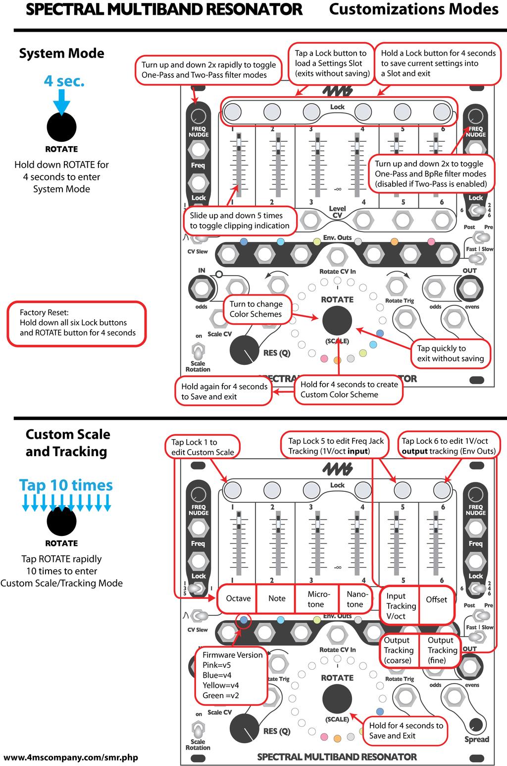
23 23
Spectral Multiband Resonator from 4ms Company Eurorack Module User Manual v1.0 (July 2015)
") Spectral Multiband Resonator from 4ms Company Eurorack Module User Manual v1.0 (July 2015) The Spectral Multiband Resonator from 4ms Company is a versatile resonant filter with six bandpass resonators/filters
Spectral Multiband Resonator from 4ms Company Eurorack Module User Manual v1.0 (July 2015) The Spectral Multiband Resonator from 4ms Company is a versatile resonant filter with six bandpass resonators/filters
Quad Clock Distributor (QCD) from 4ms Company
 from 4ms Company") Quad Clock Distributor (QCD) from 4ms Company Eurorack Module User Manual v1.0 (2013-12-09) The Quad Clock Distributor (QCD) from 4ms Company is a four channel Voltage Controlled Clock Divider/Multiplier
Quad Clock Distributor (QCD) from 4ms Company Eurorack Module User Manual v1.0 (2013-12-09) The Quad Clock Distributor (QCD) from 4ms Company is a four channel Voltage Controlled Clock Divider/Multiplier
4ms Quad Pingable LFO
 4ms Quad Pingable LFO Eurorack Module User Manual v2013-04-04 (pre-release) The Quad Pingable LFO (QPLFO) from 4ms Company is a compact, playable quad modulation source of four independent and identical
Tiptop audio z-dsp.
 Tiptop audio z-dsp www.tiptopaudio.com Introduction Welcome to the world of digital signal processing! The Z-DSP is a modular synthesizer component that can process and generate audio using a dedicated
Synthesis Technology E102 Quad Temporal Shifter User Guide Version 1.0. Dec
 Synthesis Technology E102 Quad Temporal Shifter User Guide Version 1.0 Dec. 2014 www.synthtech.com/euro/e102 OVERVIEW The Synthesis Technology E102 is a digital implementation of the classic Analog Shift
Edit Menu. To Change a Parameter Place the cursor below the parameter field. Rotate the Data Entry Control to change the parameter value.
 The Edit Menu contains four layers of preset parameters that you can modify and then save as preset information in one of the user preset locations. There are four instrument layers in the Edit menu. See
Tetrapad Manual. Tetrapad. Multi-Dimensional Performance Touch Controller. Firmware: 1.0 Manual Revision:
 Tetrapad Multi-Dimensional Performance Touch Controller Firmware: 1.0 Manual Revision: 2017.11.15 Table of Contents Table of Contents Overview Installation Before Your Start Installing Your Module Panel
Noise Tools 1U Manual. Noise Tools 1U. Clock, Random Pulse, Analog Noise, Sample & Hold, and Slew. Manual Revision:
 Noise Tools 1U Clock, Random Pulse, Analog Noise, Sample & Hold, and Slew Manual Revision: 2018.05.16 Table of Contents Table of Contents Overview Installation Before Your Start Installing Your Module
Noise Tools 1U Manual. Noise Tools 1U. Clock, Random Pulse, Analog Noise, Sample & Hold, and Slew. Manual Revision:
 Noise Tools 1U Clock, Random Pulse, Analog Noise, Sample & Hold, and Slew Manual Revision: 2018.09.13 Table of Contents Table of Contents Compliance Installation Before Your Start Installing Your Module
5U Oakley Modular Series
 Oakley Sound Systems 5U Oakley Modular Series VC-LFO Low Frequency Oscillator PCB Issue 2 User Manual V2.0.04 Tony Allgood B.Eng PGCE Oakley Sound Systems CARLISLE United Kingdom The suggested panel layout
Dual Looping Delay from 4ms Company Eurorack Module User Manual 1.1c (2017-January-11) Firmware version 5
 Firmware version 5") Dual Looping Delay from 4ms Company Eurorack Module User Manual 1.1c (2017-January-11) Firmware version 5 The Dual Looping Delay (DLD), designed by 4ms Company and Gary Hall, is an advanced audio processor
Dual Looping Delay from 4ms Company Eurorack Module User Manual 1.1c (2017-January-11) Firmware version 5 The Dual Looping Delay (DLD), designed by 4ms Company and Gary Hall, is an advanced audio processor
QUAD LFO MANUAL V SE 14TH AVENUE PORTLAND OR USA
 www.malekkoheavyindustry.com 814 SE 14TH AVENUE PORTLAND OR 97214 USA TABLE OF CONTENTS SPECIFICATIONS 1 INSTALLATION 2 DESCRIPTION 3 CONTROLS 4-6 USING QUAD LFO WITH VARIGATE 8+ AND VARIGATE 4+ 7 WARRANTY
ALGORHYTHM. User Manual. Version 1.0
 !! ALGORHYTHM User Manual Version 1.0 ALGORHYTHM Algorhythm is an eight-step pulse sequencer for the Eurorack modular synth format. The interface provides realtime programming of patterns and sequencer
Vocal Processor. Operating instructions. English
 Vocal Processor Operating instructions English Contents VOCAL PROCESSOR About the Vocal Processor 1 The new features offered by the Vocal Processor 1 Loading the Operating System 2 Connections 3 Activate
R H Y T H M G E N E R A T O R. User Guide. Version 1.3.0
 R H Y T H M G E N E R A T O R User Guide Version 1.3.0 Contents Introduction... 3 Getting Started... 4 Loading a Combinator Patch... 4 The Front Panel... 5 The Display... 5 Pattern... 6 Sync... 7 Gates...
Intelligent Quantizer and Interval Generator
 µscale Intelligent Quantizer and Interval Generator Manual Revision: 2018.02.16 Table of Contents Table of Contents Overview Features Installation Before Your Start Installing Your Module Front Panel Controls
Modcan Touch Sequencer Manual
 Modcan Touch Sequencer Manual Normal 12V operation Only if +5V rail is available Screen Contrast Adjustment Remove big resistor if using with PSU with 5V rail Jumper TOP VEIW +5V (optional) +12V } GND
XYNTHESIZR User Guide 1.5
 XYNTHESIZR User Guide 1.5 Overview Main Screen Sequencer Grid Bottom Panel Control Panel Synth Panel OSC1 & OSC2 Amp Envelope LFO1 & LFO2 Filter Filter Envelope Reverb Pan Delay SEQ Panel Sequencer Key
Oberkorn User Manual. Analogue Sequencer. Analogue Solutions
 Oberkorn User Manual Analogue Sequencer Analogue Solutions CONTENTS What is an analogue sequencer?... 4 That s all very well (and technical) but what would I use it for?... 4 ABOUT THIS MANUAL AND ABOUT
VARIGATE 4+ MANUAL V.1
 www.malekkoheavyindustry.com 814 SE 14TH AVENUE PORTLAND OR 97214 USA TABLE OF CONTENTS SPECIFICATIONS 1 INSTALLATION 2 DESCRIPTION 3 OVERVIEW 4-5 PROGRAMMING GATES PER STEP 6 PROGRAMMING CV/NOTES PER
Table of Contents: ECHOPHON
 v2.6 Table of Contents: 2 ECHOPHON FCC -----------------------------------------------------3 Limited Warranty ----------------------------------------4 Installation --------------------------------------------------5
QUAD ENVELOPE MANUAL V.1
 www.malekkoheavyindustry.com 814 SE 14TH AVENUE PORTLAND OR 97214 USA TABLE OF CONTENTS SPECIFICATIONS 1 INSTALLATION 2 DESCRIPTION 3 CONTROLS 4-6 MEASUREMENTS 7 USING QUAD ENVELOPE WITH VARIGATE 8+ AND
Musical Acoustics Lecture 15 Pitch & Frequency (Psycho-Acoustics)
") 1 Musical Acoustics Lecture 15 Pitch & Frequency (Psycho-Acoustics) Pitch Pitch is a subjective characteristic of sound Some listeners even assign pitch differently depending upon whether the sound was
1 Musical Acoustics Lecture 15 Pitch & Frequency (Psycho-Acoustics) Pitch Pitch is a subjective characteristic of sound Some listeners even assign pitch differently depending upon whether the sound was
Written by Jered Flickinger Copyright 2019 Future Retro
 Written by Jered Flickinger Copyright 2019 Future Retro www.future-retro.com 2 TABLE OF CONTENTS Page 4 - Overview Page 5 Controls Page 6 Inputs and Outputs Page 7 MIDI Page 8 Jumper Settings Page 9 Standalone
Dave Jones Design Phone: (607) Lake St., Owego, NY USA
 Lake St., Owego, NY USA") Manual v1.00a June 1, 2016 for firmware vers. 2.00 Dave Jones Design Phone: (607) 687-5740 34 Lake St., Owego, NY 13827 USA www.jonesvideo.com O Tool Plus - User Manual Main mode NOTE: New modules are
Manual v1.00a June 1, 2016 for firmware vers. 2.00 Dave Jones Design Phone: (607) 687-5740 34 Lake St., Owego, NY 13827 USA www.jonesvideo.com O Tool Plus - User Manual Main mode NOTE: New modules are
multitrack sequencer USER GUIDE Social Entropy Electronic Music Instruments
 multitrack sequencer Social Entropy Electronic Music Instruments IMPORTANT SAFETY AND MAINTENANCE INSTRUCTIONS TABLE OF CONTENTS BACKGROUND... 1 CONCEPTS... 2 DIAGRAM CONVENTIONS... 3 THE BASICS WHAT
ADSR AMP. ENVELOPE. Moog Music s Guide To Analog Synthesized Percussion. The First Step COMMON VOLUME ENVELOPES
 Moog Music s Guide To Analog Synthesized Percussion Creating tones for reproducing the family of instruments in which sound arises from the striking of materials with sticks, hammers, or the hands. The
Plog rev 1.0 MANUAL Overview
 Overview The Intellijel Plog is a voltage controllable digital logic device designed for musical applications. It is primarily intended to create controllable patterns from gate/ pulse sources like clocks
Shifty Manual. Shifty. Voice Allocator Hocketing Controller Analog Shift Register Sequential/Manual Switch. Manual Revision:
 Shifty Voice Allocator Hocketing Controller Analog Shift Register Sequential/Manual Switch Manual Revision: 2018.10.14 Table of Contents Table of Contents Compliance Installation Installing Your Module
STX Stairs lighting controller.
 Stairs lighting controller STX-1795 The STX-1795 controller serves for a dynamic control of the lighting of stairs. The lighting is switched on for consecutive steps, upwards or downwards, depending on
Original Marketing Material circa 1976
 Original Marketing Material circa 1976 3 Introduction The H910 Harmonizer was pro audio s first digital audio effects unit. The ability to manipulate time, pitch and feedback with just a few knobs and
Four Head dtape Echo & Looper
 Four Head dtape Echo & Looper QUICK START GUIDE Magneto is a tape-voiced multi-head delay designed for maximum musicality and flexibility. Please download the complete user manual for a full description
Time Fabric. Pitch Programs for Z-DSP
 Time Fabric Pitch Programs for ZDSP Time Fabric Pitch Programs for ZDSP It fucks with the fabric of time! Tony Visconti describing Pitch Shifting to Brian Eno and David Bowie in 1976 That not so subtle
Pressure Points. v. 2.5
 Pressure Points v. 2.5 2 Pressure Points FCC-------------------------------------------------------------------3 Limited Warranty ----------------------------------------------------4 Installation ----------------------------------------------------5
Liquid Mix Plug-in. User Guide FA
 Liquid Mix Plug-in User Guide FA0000-01 1 1. COMPRESSOR SECTION... 3 INPUT LEVEL...3 COMPRESSOR EMULATION SELECT...3 COMPRESSOR ON...3 THRESHOLD...3 RATIO...4 COMPRESSOR GRAPH...4 GAIN REDUCTION METER...5
User Guide. Version 2.0.0
 II User Guide Version 2.0.0 Contents Introduction... 3 What s New in Step Note Recorder II?... 3 Getting Started... 4 The Front Panel... 5 The Sequence... 5 The Piano Roll... 6 The Data Lane... 7 Velocity...
NAVIGATOR OWNER S MANUAL
 OWNER S MANUAL UNCHARTED WATERS, NEW HORIZONS Making shapes spin and move is notoriously difficult for pattern synthesis based only on oscillators synchronized to horizontal and vertical frequency ranges.
MantaMate User Manual. Snyderphonics
 MantaMate User Manual Snyderphonics Version 0.7, July 30, 2017 Contents Preface 1 Setting up the MantaMate 1 1.1 Connecting Power......................... 1 1.2 Output Voltage Range Jumper..................
// K4815 // Pattern Generator. User Manual. Hardware Version D-F Firmware Version 1.2x February 5, 2013 Kilpatrick Audio
 // K4815 // Pattern Generator Kilpatrick Audio // K4815 // Pattern Generator 2p Introduction Welcome to the wonderful world of the K4815 Pattern Generator. The K4815 is a unique and flexible way of generating
Understanding and Using Your moogerfooger MF-105 MuRF
 Understanding and Using Your moogerfooger MF-105 MuRF TABLE OF CONTENTS Getting Started...3 Frequencies and Filters...5 The MuRF s Filters...7 Envelope Generators...10 Sequencers and Pattern Generation...11
SNAZZY FX TELEPHONE GAME MANUAL REV1 2015
 SNAZZY FX TELEPHONE GAME MANUAL REV1 2015 WELCOME TO THE 2015 TELEPHONE GAME MANUAL!! There is a lot of information here, in many different forms, taken from a variety of different times. While some may
y POWER USER MUSIC PRODUCTION and PERFORMANCE With the MOTIF ES Mastering the Sample SLICE function
 y POWER USER MUSIC PRODUCTION and PERFORMANCE With the MOTIF ES Mastering the Sample SLICE function Phil Clendeninn Senior Product Specialist Technology Products Yamaha Corporation of America Working with
CVP-609 / CVP-605. Reference Manual
 CVP-609 / CVP-605 Reference Manual This manual explains about the functions called up by touching each icon shown in the Menu display. Please read the Owner s Manual first for basic operations, before
MP212 Principles of Audio Technology II
 MP212 Principles of Audio Technology II Black Box Analysis Workstations Version 2.0, 11/20/06 revised JMC Copyright 2006 Berklee College of Music. All rights reserved. Acrobat Reader 6.0 or higher required
fxbox User Manual P. 1 Fxbox User Manual
 fxbox User Manual P. 1 Fxbox User Manual OVERVIEW 3 THE MICROSD CARD 4 WORKING WITH EFFECTS 4 MOMENTARILY APPLY AN EFFECT 4 TRIGGER AN EFFECT VIA CONTROL VOLTAGE SIGNAL 4 TRIGGER AN EFFECT VIA MIDI INPUT
Please contact with any questions, needs & comments... otherwise go MAKE NOISE.
 soundhack ECHOPHON Limited WARRANTY: Make Noise warrants this product to be free of defects in materials or construction for a period of two years from the date of manufacture. Malfunction resulting from
Description. Never run out of envelopes again.
 Contour Description Never run out of envelopes again. Contour is a quad envelope generator. Each channel has looping, CV over attack and decay, as well as unique chaining capabilities. This makes for the
Element 78 MPE-200. by Summit Audio. Guide To Operations. for software version 1.23
 Element 78 MPE-200 by Summit Audio Guide To Operations for software version 1.23 TABLE OF CONTENTS IMPORTANT SAFETY AND GROUNDING INSTRUCTIONS COVER 1. UNPACKING AND CONNECTING...3 AUDIO CONNECTIONS...4
CLA MixHub. User Guide
 CLA MixHub User Guide Contents Introduction... 3 Components... 4 Views... 4 Channel View... 5 Bucket View... 6 Quick Start... 7 Interface... 9 Channel View Layout..... 9 Bucket View Layout... 10 Using
Polytek Reference Manual
 Polytek Reference Manual Table of Contents Installation 2 Navigation 3 Overview 3 How to Generate Sounds and Sequences 4 1) Create a Rhythm 4 2) Write a Melody 5 3) Craft your Sound 5 4) Apply FX 11 5)
randomrhythm Bedienungsanleitung User Guide
 randomrhythm Bedienungsanleitung User Guide EN Foreword Whether random really exists or is just an illusion, shall be discussed by philosophers and mathematicians. At VERMONA, we found a possibility to
// K4815 // Pattern Generator. User Manual. Hardware Version D/E Firmware Version 1.1x February 16, 2011 Kilpatrick Audio
 // K4815 // Pattern Generator Kilpatrick Audio // K4815 // Pattern Generator 2p Introduction Welcome to the wonderful world of the K4815 Pattern Generator. The K4815 is a unique and flexible way of generating
Understanding and Using Your Moogerfooger MF-105B Bass MuRF
 Understanding and Using Your Moogerfooger MF-105B Bass MuRF TABLE OF CONTENTS Getting Started...3 Frequencies and Filters...5 The Bass MuRF s Filters...7 Envelope Generators...10 Sequencers and Pattern
Eventide Inc. One Alsan Way Little Ferry, NJ
 Copyright 2017, Eventide Inc. P/N 141298, Rev 3 Eventide is a registered trademark of Eventide Inc. AAX and Pro Tools are trademarks of Avid Technology. Names and logos are used with permission. Audio
Sequencer 1 User s Guide
 Sequencer 1 User s Guide Audio Damage, Inc. For Firmware Version 1.5.0 22 December 2016 The information in this document is subject to change without notice and does not represent a commitment on the part
Credits:! Product Idea: Tilman Hahn Product Design: Tilman Hahn & Dietrich Pank Product built by: Dietrich Pank Gui Design: Benjamin Diez
 whoosh 1.1 owners manual Document Version: 2.0 Product Version: 1.1 System Requirements: Mac or PC running the full version of Native Instruments Reaktor 5.9 and up. For Protools users: We no longer support
Shifty Manual v1.00. Shifty. Voice Allocator / Hocketing Controller / Analog Shift Register
 Shifty Manual v1.00 Shifty Voice Allocator / Hocketing Controller / Analog Shift Register Table of Contents Table of Contents Overview Features Installation Before Your Start Installing Your Module Front
III Phrase Sampler. User Manual
 III Phrase Sampler User Manual Version 3.3 Software Active MIDI Sync Jun 2014 800-530-4699 817-421-2762, outside of USA mnelson@boomerangmusic.com Boomerang III Phrase Sampler Version 3.3, Active MIDI
COPYING A PATTERN...35
 f TABLE OF CONTENTS INTRODUCTION...5 WELCOME TO THE SR18 DRUM MACHINE!...5 GROUND RULES...5 CONNECTION DIAGRAM...8 TOP PANEL PHYSICAL LAYOUT...9 GENERAL CONTROLS...9 NAVIGATION BUTTONS...10 MODE BUTTONS...10
Sandman Pro 1.1 Manual. by unfilteredaudio
 Sandman Pro 1.1 Manual by unfilteredaudio Introduction Sandman Pro is the delay of your dreams: a multi-mode delay workstation with unmatched loopfreezing capabilities. Sandman Pro builds on the legacy
Rebis Audio Ltd. RA226 Digital Sampler User Guide
 Rebis Audio Ltd. RA226 Digital Sampler User Guide CONTENTS Page Caution 2 Powering Up 2 Controls 3, 4 Detailed Description Input Level Set 5 Recording 5 Sampling 5 Multiple Samples 6 Editing 6 Playback
LS1lightstrip User s Manual. Introduction Care and feeding Specifications. soundmachines user manual 1 LS1lightstrip
 User s Manual Introduction Care and feeding Specifications soundmachines user manual 1 Introduction The is a capacitive slider that will generate CV and GATE signals along with the movement of your finger
NoteMix Player Note Mixer/Shifter/Splitter/Filter with Snapshot Morphing Rack Extension for Propellerhead Reason
 NoteMix Player Note Mixer/Shifter/Splitter/Filter with Snapshot Morphing Rack Extension for Propellerhead Reason USER MANUAL version 1.0.0 NoteMix User Manual www.retouchcontrol.com Page 1 of 26 Table
Reason Overview3. Reason Overview
 Reason Overview3 In this chapter we ll take a quick look around the Reason interface and get an overview of what working in Reason will be like. If Reason is your first music studio, chances are the interface
MAutoPitch. Presets button. Left arrow button. Right arrow button. Randomize button. Save button. Panic button. Settings button
 MAutoPitch Presets button Presets button shows a window with all available presets. A preset can be loaded from the preset window by double-clicking on it, using the arrow buttons or by using a combination
Fraction by Sinevibes audio slicing workstation
 Fraction by Sinevibes audio slicing workstation INTRODUCTION Fraction is an effect plugin for deep real-time manipulation and re-engineering of sound. It features 8 slicers which record and repeat the
Understanding and Using Your moogerfooger MF-105M MIDI MuRF
 Understanding and Using Your moogerfooger MF-105M MIDI MuRF TABLE OF CONTENTS Getting Started...3 Frequencies and Filters...5 The MIDI MuRF s Filters...7 Envelope Generators...10 Sequencers and Pattern
spiff manual version 1.0 oeksound spiff adaptive transient processor User Manual
 oeksound spiff adaptive transient processor User Manual 1 of 9 Thank you for using spiff! spiff is an adaptive transient tool that cuts or boosts only the frequencies that make up the transient material,
XILS 3. User Manual
 XILS 3 User Manual www.xils-lab.com - 1 - Table of contents 1 Introduction... 3 2 Features... 5 3 Installation... 6 3.1 Windows (XP, VISTA)... 6 3.2 Mac (OSX 10.3.9 and later)... 6 4 Quick Start... 7 4.1
First things first. Visit us:
 Flight Plan v. 1.2 First things first RTFM be so kind and read the manual. It will provide you with the information you need to fully indulge in the module you just purchased for which we like to thank
Eventide Inc. One Alsan Way Little Ferry, NJ
 Copyright 2017, Eventide Inc. P/N: 141218, Rev 7 Eventide is a registered trademark of Eventide Inc. AAX and Pro Tools are trademarks of Avid Technology. Names and logos are used with permission. Audio
KAMIENIEC. analog resonant phase rotator. Model of operator s manual rev. 1977/1.0
 KAMIENIEC analog resonant phase rotator operator s manual rev. 1977/1.0 Model of 1977 module explained 20 SALUT Thank you for purchasing this Xaoc Devices product. Kamieniec is an analog signal processing
For example, an indication of Range: 60, 67, 72, 75 (Hz) means that 60 Hz is the default value.
 means that 60 Hz is the default value.") Owner s Manual This manual explains how to use an MV-8000 in which System Program Version 3.0 is installed. About the Symbols and icons in this manual Text in square brackets [ ] refers to buttons on the
Owner s Manual This manual explains how to use an MV-8000 in which System Program Version 3.0 is installed. About the Symbols and icons in this manual Text in square brackets [ ] refers to buttons on the
DAT335 Music Perception and Cognition Cogswell Polytechnical College Spring Week 6 Class Notes
 DAT335 Music Perception and Cognition Cogswell Polytechnical College Spring 2009 Week 6 Class Notes Pitch Perception Introduction Pitch may be described as that attribute of auditory sensation in terms
BINARY Zone. BLACET RESEARCH MODEL BZ2300 Binary Zone Module. User Manual
 BINARY Zone BLACET RESEARCH MODEL BZ2300 Binary Zone Module User Manual Blacet Research 15210 Orchard Rd Guerneville CA 95446 blacet@blacet.com http://www.blacet.com 707-869-9164 Contents Copyright. Reproduction
For sforzando. User Manual
 For sforzando User Manual Death Piano User Manual Description Death Piano for sforzando is a alternative take on Piano Sample Libraries that celebrates the obscure. Full of reverse samples, lo-fi gritty
USER S GUIDE DSR-1 DE-ESSER. Plug-in for Mackie Digital Mixers
 USER S GUIDE DSR-1 DE-ESSER Plug-in for Mackie Digital Mixers Iconography This icon identifies a description of how to perform an action with the mouse. This icon identifies a description of how to perform
BER MEASUREMENT IN THE NOISY CHANNEL
 BER MEASUREMENT IN THE NOISY CHANNEL PREPARATION... 2 overview... 2 the basic system... 3 a more detailed description... 4 theoretical predictions... 5 EXPERIMENT... 6 the ERROR COUNTING UTILITIES module...
S I N E V I B E S FRACTION AUDIO SLICING WORKSTATION
 S I N E V I B E S FRACTION AUDIO SLICING WORKSTATION INTRODUCTION Fraction is a plugin for deep on-the-fly remixing and mangling of sound. It features 8x independent slicers which record and repeat short
Presents. Crystal Glasses V3. for NI KONTAKT 4+ Go to Index: 2
 Presents Crystal Glasses V3 for NI KONTAKT 4+ 1 Index Index 2 About the Crystal Glasses V3 3 Crystal Articulations/Instruments General Stuff 4 7 About the Presets 8 The Instrument Panel 9 The Main Page
oberkorn3 analogue sequencer user manual analogue sequencer user manual ANALOGUE SOLUTIONS oberkorn mkiii e&oe (c)
") oberkorn3 analogue sequencer user manual analogue sequencer user manual ANALOGUE SOLUTIONS oberkorn mkiii e&oe (c) 10-2006 1 Contents Intro - OBERKORN - Professional Analogue Sequencer...4 About Analogue
oberkorn3 analogue sequencer user manual analogue sequencer user manual ANALOGUE SOLUTIONS oberkorn mkiii e&oe (c) 10-2006 1 Contents Intro - OBERKORN - Professional Analogue Sequencer...4 About Analogue
TF5 / TF3 / TF1 DIGITAL MIXING CONSOLE. TF Editor User Guide
 TF5 / TF3 / TF1 DIGITAL MIXING CONSOLE EN Special notices Copyrights of the software and this document are the exclusive property of Yamaha Corporation. Copying or modifying the software or reproduction
Introduction! User Interface! Bitspeek Versus Vocoders! Using Bitspeek in your Host! Change History! Requirements!...
 version 1.5 Table of Contents Introduction!... 3 User Interface!... 4 Bitspeek Versus Vocoders!... 6 Using Bitspeek in your Host!... 6 Change History!... 9 Requirements!... 9 Credits and Contacts!... 10
A-134 VC Panning Module
 doepfer System A - 100 Voltage Controlled Panning A-134 1. Introduction A-134 VC Panning Module CV 1 Pan Module A-134 (PAN) is designed to provide voltagecontrolled panning for audio signals. It can equally
Polyend Poly Polyphonic MIDI to CV Converter User Manual
 Polyend Poly Polyphonic MIDI to CV Converter User Manual Made in Poland polyend.com Polyend Poly Polyphonic MIDI to CV Converter in the Eurorack format Poly is probably the easiest entry point for exploring
User Guide Version 1.1.0
 obotic ean C R E A T I V E User Guide Version 1.1.0 Contents Introduction... 3 Getting Started... 4 Loading a Combinator Patch... 5 The Front Panel... 6 On/Off... 6 The Display... 6 Reset... 7 Keys...
An Introduction to the Spectral Dynamics Rotating Machinery Analysis (RMA) package For PUMA and COUGAR
 package For PUMA and COUGAR") An Introduction to the Spectral Dynamics Rotating Machinery Analysis (RMA) package For PUMA and COUGAR Introduction: The RMA package is a PC-based system which operates with PUMA and COUGAR hardware to
An Introduction to the Spectral Dynamics Rotating Machinery Analysis (RMA) package For PUMA and COUGAR Introduction: The RMA package is a PC-based system which operates with PUMA and COUGAR hardware to
PHYSICS OF MUSIC. 1.) Charles Taylor, Exploring Music (Music Library ML3805 T )
 Charles Taylor, Exploring Music (Music Library ML3805 T )") REFERENCES: 1.) Charles Taylor, Exploring Music (Music Library ML3805 T225 1992) 2.) Juan Roederer, Physics and Psychophysics of Music (Music Library ML3805 R74 1995) 3.) Physics of Sound, writeup in this
REFERENCES: 1.) Charles Taylor, Exploring Music (Music Library ML3805 T225 1992) 2.) Juan Roederer, Physics and Psychophysics of Music (Music Library ML3805 R74 1995) 3.) Physics of Sound, writeup in this
SYMPHOBIA COLOURS: ANIMATOR
 REFERENCE MANUAL SYMPHOBIA COLOURS: ANIMATOR PROJECTSAM cinematic sampling REFERENCE MANUAL SYMPHOBIA COLOURS: ANIMATOR INTRODUCTION 3 INSTALLATION 4 PLAYING THE LIBRARY 5 USING THE INTERFACE 7 CONTACT
Reference Manual. Using this Reference Manual...2. Edit Mode...2. Changing detailed operator settings...3
 Reference Manual EN Using this Reference Manual...2 Edit Mode...2 Changing detailed operator settings...3 Operator Settings screen (page 1)...3 Operator Settings screen (page 2)...4 KSC (Keyboard Scaling)
Bionic Supa Delay Disciples Edition
 Bionic Supa Delay Disciples Edition VST multi effects plug-in for Windows Version 1.0 by The Interruptor + The Disciples http://www.interruptor.ch Table of Contents 1 Introduction...3 1.1 Features...3
Sub Kick This particular miking trick is one that can be used to bring great low-end presence to the kick drum.
 Kick Drum As the heartbeat of the contemporary drum kit, the kick drum sound we ve grown accustomed to hearing is both boomy and round on the bottom and has a nice, bright click in the high mid range.
AxumVideo 0 intro. Now that you have connected the different AXUM system parts, you are ready to configure the system according to your own needs.
 AxumVideo 0 intro Now that you have connected the different AXUM system parts, you are ready to configure the system according to your own needs. On the left we see the RACK unit and on the right we see
Chapter 40: MIDI Tool
 MIDI Tool 40-1 40: MIDI Tool MIDI Tool What it does This tool lets you edit the actual MIDI data that Finale stores with your music key velocities (how hard each note was struck), Start and Stop Times
Limited WARRANTY: Make Noise implies and accepts no responsibility for harm to person or apparatus caused through operation of this product.
 Rosie Limited WARRANTY: Make Noise warrants this product to be free of defects in materials or construction for a period of one year from the date of purchase (proof of purchase/invoice required). Malfunction
ROSIE Limited Warranty Installation
 v2.3 2 ROSIE Limited Warranty -----------------------------------------------------3 Installation ----------------------------------------------------------------4 Panel Controls ---------------------------------------------------------------5
Cristina Bachmann, Heiko Bischoff, Marion Bröer, Sabine Pfeifer The information in this document is subject to change without notice and does not
 Cristina Bachmann, Heiko Bischoff, Marion Bröer, Sabine Pfeifer The information in this document is subject to change without notice and does not represent a commitment on the part of Steinberg Media Technologies
Music Representations
 Lecture Music Processing Music Representations Meinard Müller International Audio Laboratories Erlangen meinard.mueller@audiolabs-erlangen.de Book: Fundamentals of Music Processing Meinard Müller Fundamentals
MANUAL v.3 CONTACT MORE THAN LOGIC. UNITING ART + ENGINEERING.
 MANUAL v.3 MORE THAN LOGIC. UNITING ART + ENGINEERING. CONTACT email: info@meris.us phone: 747.233.1440 website: www.meris.us TABLE OF CONTENTS SECTION 1 PG. 1 FRONT PANEL CONTROLS SECTION 2 PG. 2-4 GLOBAL
The MPC X & MPC Live Bible 1
 The MPC X & MPC Live Bible 1 Table of Contents 000 How to Use this Book... 9 Which MPCs are compatible with this book?... 9 Hardware UI Vs Computer UI... 9 Recreating the Tutorial Examples... 9 Initial