Tetrapad Manual. Tetrapad. Multi-Dimensional Performance Touch Controller. Firmware: 1.0 Manual Revision:
|
|
|
- Charlotte Daniels
- 6 years ago
- Views:
Transcription

1 Tetrapad Multi-Dimensional Performance Touch Controller Firmware: 1.0 Manual Revision:
2 Table of Contents Table of Contents Overview Installation Before Your Start Installing Your Module Panel Reference Modes Overview Selecting Modes Auto-Saving Mode Reset Mode 1: Faders Mode Using Faders Mode Slew Between Fader Settings Freeze All Faders Mode 2: Voltages Mode Using Voltages Mode Edit a Button s Stored Voltages Randomize a Single Stored Voltage Randomize all 8 Stored Voltages for a Button Reset a Stored Voltage to 0V Slew Between Stored Voltages Mode 3: Keyboard Mode Using Keyboard Mode EDIT VIEW: Assigning Keys According to Scale PERFORMANCE VIEW: Playing the Keyboard Slew Between Notes Mode 4: Custom Keyboard Mode Page 1
3 Using Custom Keyboard Mode Manual Note Assignment Slew Between Notes Playing the Keyboard Mode 5: Drum Mode Using Drum Mode Mode 6: LFO Mode Using LFO Mode Using LFO EDIT View Using LFO PERFORMANCE Mode Mode 7: Switches Mode Using Switches Mode Mode 8: Chord Mode Using Chord Mode Chord Selection Slew Between Chords Performing in Chord Mode Mode 9: Custom Chord Mode Using Custom Chord Mode Chord Entry Slew Between Chords Performing in Custom Chord Mode Mode 12: Global Configuration Using Global Configuration Mode Firmware Version Display Firmware Change Log Technical Specifications Page 2
4 Overview Tetrapad is a versatile, multi-dimensional, touch-sensitive control surface for Eurorack. Each of its four pads use force sensing resistors to respond to both the vertical position of your finger and its pressure. Four push encoders and a shift function give you even more tactile control over your modular system. Tetrapad operates in numerous modes each of which configures the module to perform a specific control task. Through these modes, Tetrapad can emulate a bank of faders; a voltage storage device; a finger drumming surface; a chord generator; an 8-key keyboard; four independent LFOs; or an 8-switch panel. The chosen mode determines what type of signal (CV, note, trigger, gate, etc.) is sent from each of Tetrapad s eight independent outputs, while its multitude of multi-colored LEDs keep you informed of exactly what s happening within each mode. Tetrapad automatically remembers how you ve configured each of its modes, and retains these settings when powered off. By default, Tetrapad automatically saves these settings every minute, or whenever you change modes. This makes Tetrapad ideal for live performance, since you know it will always power up with your configurations intact. Page 3
5 Installation Intellijel Eurorack modules are designed to be used with a Eurorack-compatible case and power supply. Before Your Start Before installing a new module in your case you must ensure your case s power supply has sufficient available capacity to power the module: Sum up the specified +12V current draw for all modules, including the new one. Do the same for the -12 V and +5V current draw. The current draw will be specified in the manufacturer's technical specifications for each module. Compare each of the sums to specifications for your case s power supply. Only proceed with installation if none of the values exceeds the power supply s specifications. Otherwise you must remove modules to free up capacity or upgrade your power supply. You will also need to ensure you have enough free space (hp) as well as free power headers in your case to fit the new module. You can use a tool like ModularGrid to assist in your planning. Failure to adequately power your modules may result in damage to your modules or power supply. If you are unsure, please contact us before proceeding. Installing Your Module When installing or removing a module from your case always turn off the power to the case and disconnect the power cable. Failure to do so may result in serious injury or equipment damage. Ensure the 10-pin connector on the power cable is connected correctly to the module before proceeding. The red stripe on the cable must line up with the -12V pins on the module s power connector. The pins are indicated with the label -12V, a white stripe next to the connector, the words red stripe, or some combination of those indicators. Page 4


6 Most modules will come with the cable already connected but it is good to double check the orientation. Be aware that some modules may have headers that serve other purposes so ensure the cable is connected to the right one. The other end of the cable, with a 16-pin connector, connects to the power bus board of your Eurorack case. Ensure the red stripe on the cable lines up with the -12V pins on the bus board. On Intellijel power supplies the pins are labelled with the label -12V and a thick white stripe: Page 5

7 If you are using another manufacturer s power supply, check their documentation for instructions. Once connected, the cabling between the module and power supply should resemble the picture below: Before reconnecting power and turning on your modular system, double check that the ribbon cable is fully seated on both ends and that all the pins are correctly aligned. If the pins are misaligned in any direction or the ribbon is backwards you can cause damage to your module, power supply, or other modules. After you have confirmed all the connections, you can reconnect the power cable and turn on your modular system. You should immediately check that all your modules have powered on and are functioning correctly. If you notice any anomalies, turn your system off right away and check your cabling again for mistakes. Page 6

8 Panel Reference 1. Pads 1-4 Four identical touch strips, each of which is sensitive to both vertical position and finger pressure. Depending on Tetrapad s current mode, these pads can transmit trigger signals, gate signals, quantized note values or CV in real time. 2. Level LEDs Embedded beneath the surface of each pad is a 12 LED ladder. This ladder displays different parameter values in different modes. When operating as basic faders, the LEDs represent the level of each fader; when operating as note triggers, they represent the note value; when selecting modes, they represent the mode number. Page 7
9 3. Push Encoders 1-4 Each of the four pads has its own associated push encoder, which functions differently depending on Tetrapad s current mode. For example, in Custom Chord Mode, the encoders assign a note value to each output. In LFO Mode, the encoders select the pad s waveform shape. Similarly, pressing the encoder has different functions depending on the mode. For example, in Faders Mode, pressing an encoder latches the corresponding fader s value. Not every pad uses the encoders, so please read the specific mode discussions to learn what functions are performed for each mode. 4. Pad Status LEDs 1-4 Some modes use these LEDs to indicate a pad s status. For example, they may indicate whether or not a pad s fader level is latched; or to which octave a note belongs. 5. Level Labels This vertical column of text provides meaningful labels to each of the 12 vertically stacked Level LEDs. On the left are numbers 1-12, which indicate mode numbers. On the right are note names, which indicate pitch when appropriate to the selected mode. 6. Mode Select Button Toggles Mode selection on and off. When Mode Select is on, the eight Output Status LEDs light up, and the Level LEDs within each of the four pads also light to indicate which mode is currently selected. To select different modes, rotate any of the four encoders all four Level LEDs move up/down to indicate the mode number. Press the Mode Select button again (or press any encoder) to exit mode selection. 7. Shift Button & LED Some modes offer additional feature sets, which are accessed by pressing the Shift Button. For example, LFO Mode s shift feature switches between Performance and Edit views. See the individual mode discussions to learn whether or not the Shift button is used, and what function it serves. The LED immediately above the Shift button glows green whenever a mode contains a shift feature, and it glows red when the shift feature is engaged. If the Shift LED is off, then the mode has no shift feature. Page 8
10 8. Outputs 1-8 Outputs CV, pitch, gate or trigger signals depending on the active mode. See the Modes section to learn the function of each jack in each mode 9. Output Status LEDs These LEDs serve two functions, depending on whether you re selecting modes, or actually using a particular mode. When selecting modes, the color of these LEDs glow solid and indicate the type of signal appearing at the output jack for the selected mode: Pitch CV Blue Gate/Trigger Magenta Vertical Position Green Pressure Red Other CV (i.e. LFO) Cyan When using a mode, both the color and the brightness of the LEDs provide output status information. For example, a green (position) LED gets brighter when your finger is higher up the pad; a red (pressure) LED gets brighter the harder you press a pad; Other modes make additional use of these status LEDs, and will be discussed in the Modes section of this manual. Page 9
11 Modes Overview We designed Tetrapad to provide you with tactile control of your modular synth, plus the ability to maximize the flexibility with which you wield that control. For this reason, Tetrapad is a mode-based control surface. Each mode reassigns the four touch pads, four rotary push encoders, eight outputs, numerous status LEDs and shift button. Tetrapad currently supports nine different modes (plus a separate global configuration mode) each designed to operate as a tactile control surface best-suited for its intended task. These modes are: Mode 1: Faders Mode - This mode gives you 4 pressure sensitive faders, which means each fader can generate two control voltages: one based on the vertical position of your finger; and one on pressure. Mode 2: Voltages Mode - Voltages Mode divides each pad into two regions an upper and a lower giving you access to 8 voltage banks, each of which can store 8 voltages (one for each output). Mode 3: Keyboard Mode - Keyboard Mode turns Tetrapad into an 8-key keyboard, with each key capable of sending a different note to Outs 1-4. This mode divides each of the four pads in two, creating an upper key and a lower key. Touching any pad also outputs both a trigger and a gate signal, and pads respond to both position and pressure. You define notes for each key by selecting a keyboard mapping from the built-in Scale Library and you set a root note with a twist of an encoder. Diatonically shifted versions of the root scale appear at each of the four outputs and you can rotate these assignments using another encoder. Mode 4: Custom Keyboard Mode - Custom Keyboard Mode is similar to Keyboard Mode (described above), only instead of automatically assigning keys to a particular scale, you manually assign a note to each of the eight keys (and for each of the four outputs, if you wish). Custom Keyboard Mode is for people who want direct control over the pitch of every key and output, and don t wish to be constrained by the scales included in Mode 3 s Scale Library. Mode 5: Drum Mode - Drum Mode provides you with four positionally sensitive drum pads. Each pad generates a gate signal when touched, plus a second CV based on the vertical position of your finger. Since each pad generates a gate no matter where you tap it, this mode is ideal for finger drumming, but with the possibility of additional expression via the positional output CV. Mode 6: LFO Mode - LFO mode turns Tetrapad into four independent LFO s, each with its own rate and waveshape, and with each pad offering a pressure output for additional modulation options. Page 10
12 Mode 7: Switches Mode - In this mode, Tetrapad becomes an 8-switch control panel, which you can configure as either toggle switches or momentary switches. Mode 8: Chord Mode - Chord Mode stores a unique 4-note chord for each of the four pads. Touching a pad transmits the four notes to the first four outputs, enabling you to play one-finger chords (if you use multiple oscillators). Touching any pad also outputs both a trigger and a gate signal, and pads respond to both position and pressure. Define a chord for each pad by selecting it from the built-in Chord Library, and alter the root note, inversion and chord rotations using the encoders. Mode 9: Custom Chord Mode - Custom Chord Mode is similar to Chord Mode (described above), only instead of using the encoders to select chords, roots, inversions and rotations, you manually assign pad-by-pad and output-by-output each note in each chord. Custom Chord Mode is for people with chord requirements that extend beyond those included in Mode 8 s Chord Library. In addition, there is a special global configuration mode, which is assigned to Mode 12: Mode 12: Global Configuration - This is a special mode, which you use to configure Tetrapad s pressure response to match your own preferences. Unlike the first eight modes, Global Configuration mode is not meant for performance nor for controlling other modules. Selecting Modes To select different modes on Tetrapad: 1. Press the white Mode Select button to enter Mode Selection. 2. Rotate any of the four encoders to select the desired mode. The Level LEDs embedded beneath each pad will move up or down the pads. The position number (as indicated by the Level Labels in the middle of the Tetrapad) corresponds to the mode. So if the row of Level LEDs next to Level Label 4 is lit, then you re selecting Mode 4; if the row of Level LEDs next to Level Label 7 is lit, then you re selecting Mode 7; etc. Note that the eight Output Status LEDs will change colors as you cycle through the modes. These colors indicate what type of signal appears at each output for each mode. These will be discussed in the mode-specific sections of this manual. 3. Press the white Mode Select button again to exit mode selection. Your Tetrapad will now operate in this mode. Note that you can also click any of the four encoders to exit mode selection. Page 11
13 TIP: If you forget what type of signal appears at each of the eight output jacks, simply press the white Mode Select button the LEDs under each jack light to indicate the type of signal present at that jack (as discussed earlier, under Output Status LEDs ). Press the Mode Select button again to exit mode selection. Auto-Saving Tetrapad retains all mode settings while powered on thus insuring that you can switch freely between modes in a performance, knowing that when you return to a mode, it will always be exactly as you left it. In addition, Tetrapad remembers many of its settings when powered off. Specifically, it remembers all the critical configuration parameters for each mode (for example: slew rates; note assignments in keyboard mode; voltages in voltage mode; chord assignments in chord mode; etc) but it does not retain settings that might be specific to a performance, such as: fader values; LFO speeds; most-recently touch key or pad; etc). By default, Tetrapad automatically saves its settings every minute, or whenever you change modes. This makes Tetrapad ideal for live performance, since it will always power up with your carefully configured modes still intact and ready to perform. Mode Reset In spite of the obvious advantages gained by Tetrapad s Auto-Save feature, you may sometimes prefer to program a mode from scratch rather than modifying a previously saved configuration. For this reason, Tetrapad provides a Mode Reset feature: 1. Press the white Mode Select button to enter Mode Selection, and rotate any of the four encoders to select the mode you wish to reset. 2. Press the red Shift button and, while holding it down, exit Mode Selection (by clicking either the white Mode Select button or any of the four push encoders). Tetrapad resets that mode to the factory default settings. NOTE: You can also reset all Modes simultaneously (along with the Global Configuration Settings) by using this same technique with Mode 12 selected. Page 12
 to exit mode selection.")
14 Mode 1: Faders Mode Press the white Mode Select button and rotate any of the four encoders to select Mode 1, which occurs when the row of Level LEDs light next to Level Label 1. Press the white Mode Select button again (or press any encoder) to exit mode selection. Faders Mode gives you 4 pressure sensitive faders, which means each fader can generate two control voltages: one based on the vertical position of your finger; and one on pressure. Page 13
15 Using Faders Mode 1. Slide a finger up and down each pad, just as if you were moving an actual fader. Alternately, you can simply tap a pad anywhere along its vertical scale, and the fader will jump to that level directly (using a slew rate you define, as discussed shortly). Tetrapad sends each fader s vertical position CV to its odd numbered output. That is, Pad 1 sends fader values to Out 1; Pad 2 sends fader values to Out 3; etc. Each Output Status LED lights green to represent the presence of a CV signal, while the brightness of each LED indicates its absolute value, from 0 to +5V. 2. Press down on a pad to send an additional pressure-sensitive CV to the corresponding even numbered output. That is, Pad 1 sends its pressure value to Out 2; Pad 2 sends it to Out 4; etc. Each Output Status LED lights red to represent the presence of a pressure CV signal, while the brightness of each LED indicates its absolute value, from 0 to +5V. 3. Press a fader s corresponding encoder to latch that fader. Latched faders are indicated by a blue Pad Status LED and can be assigned on a fader-by-fader basis. When a fader is latched, it remains at the last level touched much like a real fader on an analog mixing console. When a fader is unlatched (the Status LED is off), it snaps back to its minimum value when you release it much like the spring-loaded modulation wheel used by some synths. Page 14
16 Slew Between Fader Settings If you prefer to tap faders (rather than drag them) or if you use latch mode, you ll appreciate the ability to set the rate at which fader values move from one touched level to the next. Each of Tetrapad s four faders can have its own slew rate. 1. Hold down the red SHIFT button and rotate the encoder above each fader to set its slew rate. Clockwise turns increase the time it takes to move from one fader value to another (up to a maximum of about 4 sec to move between min/max levels). Counterclockwise turns decrease the amount of time it takes to move from one fader value to another (down to instantaneous ). Slew times are indicated by a red Pad Status LED above each fader with an LED glowing increasingly brighter as the slew gets longer. Since latched faders cause the Pad Status LED to turn blue, slew rates applied to a latched fader cause increasing amounts of red to mix with the blue LED, ultimately resulting in a purple LED at maximum slew rate. Freeze All Faders You can freeze the position and pressure level of each fader at its current level. 1. Press the red Shift button to freeze the output of each fader (including its pressure value). The Shift LED will glow blue, and any faders currently slewing to a new value will be frozen mid-slew. Any currently unlatched faders will also freeze at the current position of your finger, regardless of whether they re latched or not. 2. Press the red Shift button again to unfreeze the faders. Page 15
 to exit mode selection.")
17 Mode 2: Voltages Mode Press the white Mode Select button and rotate any of the four encoders to select Mode 2, which occurs when the row of Level LEDs light next to Level Label 2. Press the white Mode Select button again (or press any encoder) to exit mode selection. Voltages Mode divides each pad into two regions an upper and a lower giving you access to 8 stored voltages per OUTPUT! That s right, each of Tetrapad s eight outputs has its own bank of 8 virtual buttons, each of which can store a voltage value specifically for that output, meaning you have 64 voltage storage locations in total. Page 16

18 Imagine pushing a single button that sends one voltage to a filter s frequency, another voltage to resonance, a third to a Quadra Expander s attack CV and a fourth to its decay CV. You could use the fifth output to change waveshapes on a Shapeshifter, and the sixth to set the amount of wave folding. Output 7 could change the grain size in Rainmaker, while Out 8 could adjust its wet/dry mix. In other words, used this way, Voltages Mode is almost like having patch memory within Eurorack. Using Voltages Mode Each pad is divided into two regions: an upper and a lower, meaning you have eight voltage storage locations, each accessed by its own virtual button. 1. Touch one of the eight virtual buttons to transmit up to eight different voltage values from each of Tetrapad s eight outputs. Notice that a group of four Level LEDs light on the pad, indicating which virtual button you just touched. Page 17
19 Edit a Button s Stored Voltages 1. Touch one of Tetrapad s eight virtual buttons to select it for editing (each of the four pads is divided into two regions: an upper half and a lower half, giving eight virtual buttons). 2. To assign voltages to Outputs 1-4, make sure the Shift LED is green, then rotate encoders 1-4, which assigns voltages to Outputs 1-4 respectively. NOTE: If the Shift LED is currently red, push the Shift button to toggle it to the green state) Turning an encoder clockwise assigns increasingly higher positive voltages (up to +5 V), which are indicated by the intensity of the Output Status LED, which glows green to indicate that the voltage is positive. Turning an encoder counter-clockwise sets increasingly larger negative voltages (up to -5 V), which are indicated by the intensity of the Output Status LED, which glows red to indicate the voltage is negative. 3. To assign voltages to Outputs 5-8, make sure the Shift LED is red, then rotate encoders 1-4, which assigns voltages to Outputs 5-8 respectively. NOTE: If the Shift LED is currently green, push the Shift button to toggle it to the red state. Randomize a Single Stored Voltage Those of you who prefer the serendipity approach to sound design will appreciate Tetrapad s random voltage assignment feature. To randomize a single output voltage: 1. Touch and hold the desired button (do not release your finger from the pad). Then, with your finger still on the virtual button, rotate the encoder assigned to the output you wish to randomize. For example, if you hold your finger on the top left virtual button while turning Encoder #2, then with each click of the encoder, you will assign a new random voltage to Output 2 (or Output 6 if the Shift LED is red). Page 18
20 Randomize all 8 Stored Voltages for a Button Those of you who prefer the serendipity approach to sound design and who like it applied judiciously will appreciate this feature, which lets you select a virtual button and randomize all 8 Outputs simultaneously. 1. Touch and hold the desired button (do not release your finger from the pad). Then, with your finger still on the virtual button, press Tetrapad s little red SHIFT button. A random voltage will be assigned to each of that button s 8 outputs. Each time you press the SHIFT button, you ll generate a new set of 8 output voltages. Reset a Stored Voltage to 0V 1. Touch and hold the desired button (do not release your finger from the pad). Then with your finger still on the virtual button, press the encoder assigned to the output you wish to reset to 0V. For example, if you hold your finger on the top left virtual button while pressing Encoder #3, then Output 3 will reset to 0V (or Output 7 if the Shift LED is red). Slew Between Stored Voltages Normally, each time you tap a different button, Tetrapad instantly sends the corresponding voltages to the 8 outputs. But Tetrapad also give you the ability to slew this voltage change meaning it s possible to morph between different collections of stored voltages, resulting in smooth (rather than instantaneou) changes. 1. Press the red Shift button and continue holding it while turning Encoder 1. Clockwise turns increase the time it takes to move from one voltage value to another (up to a maximum of about 4 sec to move between min/max levels). Counterclockwise turns decrease the amount of time it takes to move from one fader value to another (down to instantaneous ). Slew times are indicated by a red Pad Status LED above each fader with an LED glowing increasingly brighter as the slew gets longer. Note that slew time is a global setting within Voltages Mode, meaning the rate of change affects all buttons and all outputs simultaneously. Page 19
 to exit mode selection.")
21 Mode 3: Keyboard Mode Press the white Mode Select button and rotate any of the four encoders to select Mode 3, which occurs when the row of Level LEDs light next to Level Label 3. Press the white Mode Select button again (or press any encoder) to exit mode selection. Keyboard Mode turns Tetrapad into an 8-key keyboard, with each key capable of sending a different note to Outs 1-4. This mode divides each of the four pads in two, creating an upper key and a lower key. Touching any pad outputs both a trigger and a gate signal, and pads respond to both position and pressure, giving you expressive CV control over anything you want (such as a VCA level or filter frequency). Page 20
22 You define notes for each key by selecting a keyboard mapping from the built-in Scale Library and you set a root note with a twist of an encoder. Diatonically shifted versions of the root scale appear at each of the four outputs and you can rotate these assignments using another encoder. Using Keyboard Mode In Keyboard Mode, the pads serve two purposes: In PERFORMANCE View: Touch one of the eight keys (each pad is divided into an upper key and a lower key) to send a programmable pitch out each of the four outputs, enabling you to play melodies (or chords) from the Tetrapad. Gate and trigger signals are also output, as well as pressure and position. In EDIT View: When the Shift Status LED is red (EDIT view), the middle two pads display the number of the selected scale and the root of that scale. EDIT VIEW: Assigning Keys According to Scale Use EDIT View to assign the eight keys to play notes from the built-in Scale Library, and to set that scale s root note. 1. If the Shift Status LED is green, push the SHIFT Button to change its color to red. A red Status LED indicates that Tetrapad is in EDIT View.. 2. Touch any of the eight keys. Each of Tetrapad s four pads is divided into a top half and a bottom half, resulting in eight keys. When you touch a key, four LEDs light beneath your finger, indicating which key you ve pressed. 3. Release the key. The key s four indicator LEDs will dim (though remain slightly illuminated to indicate the most recently touched key). The brightly lit LED beneath Pad 2 indicates the current scale, and the brightly lit LED beneath Pad 3 represents the root of that scale. Page 21
23 4. Turn Encoder 2 to select the desired scale. Selecting a scale automatically assigns a different note within that scale to a different key. There are 12 built-in scales corresponding to the 12 LEDs on Pad 2. Tetrapad s scale library has the following scales: Memory Scale Intervals 1 Major 0, 2, 4, 5, 7, 9, 11 2 Minor 0, 2, 3, 5, 7, 8, 10 3 Dorian 0, 2, 3, 5, 7, 9, 10 4 Lydian 0, 2, 4, 5, 7, 9, 11 5 Phrygian 0, 1, 3, 5, 7, 8, 10 6 Locrian 0, 1, 3, 5, 6, 8, 10 7 Melodic Minor 0, 2, 3, 5, 7, 9, 11 8 Harmonic Minor 0, 2, 3, 5, 7, 8, 11 9 Super Locrian 0, 1, 3, 4, 6, 8, Bhairav 0, 1, 4, 5, 7, 8, Hungarian 0, 2, 3, 6, 7, 8, Enigmatic 0, 1, 4, 6, 8, 10, 11 Furthermore, selecting a scale assigns it to each of the three additional pitch outputs, but rotates their notes diatonically. This means the notes appearing at Out 2 are diatonically shifted +2; the notes appearing at Out 3 are diatonically shifted by +4; and the notes appearing at Out 4 are diatonically shifted by Turn Encoder 3 to set the root note of the scale. The root note is indicated by the LED position beneath Pad 3. Page 22

24 Keyboard Mode places the root note on the lower half of Pad 1, then maps ascending pitches L-to-R across the bottom of each pad, then L-to-R across the top of each pad, as shown in the following example: PERFORMANCE VIEW: Playing the Keyboard 1. If the Shift Status LED is red, push the SHIFT Button to change its color to green. A green Status LED indicates that Tetrapad is in PERFORMANCE View. 2. Tap any of the eight keys to send the notes (as assigned in EDIT View, discussed earlier) to Output 1. In addition, Tetrapad sends diatonically shifted versions of the scale to each of the three remaining outputs. Specifically, Out 2 is diatonically shifted +2; Out 3 is diatonically shifted by +4; and the notes appearing at Out 4 are diatonically shifted by +6. CV representing the vertical position of your tap on the key is sent to Out 5. CV representing the pressure you apply to any key is sent to Out 6. A trigger signal is sent to Out 7, and a Gate is sent to Out 8. Page 23
25 3. Rotate Encoder 1 to change the octave the keyboard s octave. Rotate clockwise to increase the octave. Octave settings above the default cause the Pad Status LED to glow green. With each subsequent octave increase, the LED will brighten. Rotate counterclockwise to decrease the octave. Octave settings below the default cause the Pad Status LED to glow red. With each subsequent octave decrease, the LED will brighten. Tetrapad gives you a 10 octave range. 4. Rotate Encoder 3 to rotate the output assignments. With each clockwise rotation, the output assignments shift to the right by 1. So if you rotate Encoder 3 one turn clockwise, the unshifted scale will appear at Out 2 (rather than Out 1); the +2 scale moves to Out 3; the +4 scale moves to Out 4; and the +6 scale moves to Out 1. NOTE: The brightest of the four blue Output Status LEDs indicates which output is currently assigned to the unshifted scale. 5. If you re using Keyboard mode to play multiple oscillators (connected to Outputs 1-4), then you can rotate Encoder 4 to invert the chord that appears at those Outputs. Clockwise rotation inverts the chord upward; counterclockwise rotation inverts the chord downward. For example, one CW turn transposes Out 1 up one octave; a second CW turn transposes Out 2 up one octave, and so on. Similarly, one CCW turn transposes Out 4 down one octave; etc. Page 24

26 The following flow diagram illustrates these instructions graphically: Slew Between Notes Tetrapad also gives you the ability to slew between notes. To do so, press the red SHIFT button and continue holding it while turning Encoder 1. Clockwise turns increase the time it takes to move from one note to another (up to a maximum of about 30 sec for a 10 octave glide). Counterclockwise turns decrease the amount of time (down to instantaneous ). Slew times are indicated by a red Pad Status LED above each fader with an LED glowing increasingly brighter as the slew gets longer. Slew time is a global setting within Keyboard Mode, meaning the rate of change affects all notes equally. Page 25
 to exit mode selection.")
27 Mode 4: Custom Keyboard Mode Press the white Mode Select button and rotate any of the four encoders to select Mode 4, which occurs when the row of Level LEDs light next to Level Label 4. Press the white Mode Select button again (or press any encoder) to exit mode selection. Custom Keyboard Mode turns Tetrapad into an 8-key keyboard, with each key capable of sending a different note to Outs 1-4. This mode divides each of the four pads in two, creating an upper key and a lower key. Touching any pad outputs both a trigger and a gate signal, and pads respond to both position and pressure, giving you expressive CV control over anything you want (such as a VCA level or filter frequency). Page 26
28 Unlike Mode 3, Custom Keyboard Mode lets you define each and every note for each and every pad on all four outputs. This allows for scales and note assignments beyond those included in Mode 3 s Scale Library. Using Custom Keyboard Mode In Custom Keyboard Mode, the pads serve two purposes: As a performance controller: touching one of the eight keys (each pad is divided into an upper key and a lower key) sends a programmable pitch out each of the four outputs, enabling you to play melodies from the Tetrapad. Gate and trigger signals are also output, as well as pressure and position. As an edit display: When you touch a key, you select it for editing (as indicated by the four dim LEDs beneath the key s surface). The four pads then display the pitch value assigned to outputs 1-4, which you edit with the corresponding encoders as discussed below. Manual Note Assignment 1. Touch one of the eight keys to play it, and to enable it for note assignment. Each of Tetrapad s four pads is divided into a top half and a bottom half, resulting in eight keys. When you touch a key, four LEDs will light beneath your finger, indicating which key you ve pressed. 2. Release the key. The key s four indicator LEDs will dim (though remain slightly illuminated to indicate the most recently touched and editable key). Notice that beneath the surface of each pad is a single brightly lit LED, whose vertical position indicates the note value that will be sent to the corresponding Output. That is, the bright LED shown beneath Pad 1 represents the note that appears at Out 1; the bright LED shown beneath Pad 2 represents the note that appears at Out 2; etc. 3. Rotate encoder 1 to change the pitch sent to Out 1. If desired, rotate encoders 2-4 to change pitch assignments for outputs 2-4. When you set a pitch that s an octave higher than default, the Pad Status LED will glow green. With each subsequent octave increase, the LED will brighten. When the pitch is an octave lower than default, the Pad Status LED will glow red. With each Page 27

29 subsequent octave decrease, the LED will brighten. Pitch can be set over a 10 octave range. 4. Touch each of the remaining seven keys and repeat step 3 to define note values for all eight keys, and for all four outputs. TIP: Reset any note to its default C (0 V) value by pressing the corresponding encoder. The following flow diagram illustrates these instructions graphically: Page 28
30 Slew Between Notes Tetrapad also gives you the ability to slew between notes. To do so, press the red Shift button and continue holding it while turning Encoder 1. Clockwise turns increase the time it takes to move from one note to another (up to a maximum of about 30 sec for a 10 octave glide). Counterclockwise turns decrease the amount of time (down to instantaneous ). Slew times are indicated by a red Pad Status LED above each fader with an LED glowing increasingly brighter as the slew gets longer. Slew time is a global setting within Keyboard Mode, meaning the rate of change affects all notes equally. Playing the Keyboard 1. Tap any of the eight keys to send the custom assigned notes to Outputs 1-4. That s it. There is no step 2. But you re free to manually reassign any note at any time using the encoders and the technique discussed earlier, in Manual Note Assignment. Page 29
 to exit mode selection. Drum Mode gives you 4 positionally sensitive drum pads.")
31 Mode 5: Drum Mode Press the white Mode Select button and rotate any of the four encoders to select Mode 5, which occurs when the row of Level LEDs light next to Level Label 5. Press the white Mode Select button again (or press any encoder) to exit mode selection. Drum Mode gives you 4 positionally sensitive drum pads. Each pad generates a gate signal when touched, plus a second CV based on the vertical position of your finger. Since each pad generates a gate no matter where you tap it, this mode is ideal for finger drumming. The even numbered outputs provide an additional source of position based modulation, which you can connect to a drum module s velocity or accent input, or anything else that benefits from CV control. Page 30
32 Using Drum Mode To use Tetrapad in Drum Mode: 1. Tap a pad to send a gate signal to the corresponding pad s odd numbered output. That is, Pad 1 sends a gate to Out 1; Pad 2 to Out 3; Pad 3 to Out 5; etc. Each odd numbered Output Status LED glows magenta, indicating it s a gate output. The brightness of this LED does not change since pressure is irrelevant in this mode. 4. Slide a finger up and down each pad to generate an additional position-sensitive CV at the corresponding pad s even numbered output. That is, Pad 1 s position value is sent to Out 2; Pad 2 s to out 4; etc. Each Output Status LED glows green to represent the presence of a position-based CV signal, while the brightness of each LED indicates its absolute value. TIP: Although the positional CV generates continuous voltages as you slide your finger up and down the pad, you might find it particularly useful to patch this output into a drum module s accent or velocity input. In this way, you control a drum s velocity value by how high you tap a pad, adding additional nuance and control to your drum performance. Page 31
 to exit mode selection.")
33 Mode 6: LFO Mode Press the white Mode Select button and rotate any of the four encoders to select Mode 6, which occurs when the row of Level LEDs light next to Level Label 6. Press the white Mode Select button again (or press any encoder) to exit mode selection. LFO mode turns Tetrapad into four independent LFOs, each with its own rate and waveshape, and with each pad offering a pressure output for additional modulation options. Page 32
34 Using LFO Mode In LFO Mode, Tetrapad continuously sends four programmable LFOs from its Odd numbered outputs. Specifically, LFO 1 appears at Out 1; LFO 2 appears at Out 3; LFO 3 appears at Out 5; and LFO 4 appears at Out 6. You can see this visually, since the Output Status LEDs for these four output are blinking (green/red; green/off; or red/off depending on LFO polarity). Pressure is sent to the Even numbered outputs. LFO Mode operates in one of two views: PERFORMANCE View (Status LED is Green) and EDIT View (Status LED is Red). We ll start by discussing EDIT View. Using LFO EDIT View 1. If the Shift Status LED is green, push the SHIFT Button to change its color to red. A red Status LED indicates the LFO is in EDIT View. 2. Adjust the rate of any LFO by touching its corresponding pad. The higher up you touch a pad, the faster the LFO rate, which is indicated by the rate at which the corresponding Output Status LED flashes. 3. Select the LFO shape by rotating its corresponding encoder. This cycles the LFO shape between Triangle, Sawtooth, Ramp (inverse saw), Square and Random. 4. Set the LFO s polarity by pressing its corresponding encoder. This cycles through three LFO polarities: bipolar; unipolar (positive only); unipolar (negative only). You can tell which polarity each LFO is currently using by monitoring the Output Status LEDs: A bipolar LFO will switch between green & red. A positive unipolar wave will switch between green & off. A negative unipolar wave will switch between red & off. 5. Press harder on a pad to send an additional pressure-sensitive CV to the corresponding Even numbered output. Note that, in LFO EDIT View, it can be difficult to transmit pressure values without accidentally changing the LFO rate. For this reason, there s also an LFO PERFORMANCE Mode Page 33
35 Using LFO PERFORMANCE Mode 1. If the Shift Status LED is red, push the SHIFT Button to change its color to green. A green Status LED indicates the LFO is in PERFORMANCE View: In LFO PERFORMANCE View, each LFO uses the waveshape and polarity defined in LFO EDIT View. So if you want to modify either of those values for an LFO, you need to temporarily switch back into LFO EDIT View. 2. As in LFO EDIT View, adjust the rate of any LFO by touching its corresponding pad. The higher up you touch the pad, the faster the LFO rate which is indicated by the rate at which the corresponding Output Status LED flashes. 3. In LFO PERFORMANCE View, you can latch an LFO rate so it doesn t change value when you touch a pad. To do this, first use the pad to set the desired LFO rate, then press the corresponding encoder button. The corresponding Pad Status LED turns blue, indicating the LFO rate is latched. Now when you touch a pad, the value does not change. This is particularly useful when you want to use the pads to transmit pressure CV without accidentally affecting the LFO rate. 4. To unlatch an LFO, simply press the encoder again, turning off its blue Pad Status LED. Page 34
 to exit mode selection.")
36 Mode 7: Switches Mode Press the white Mode Select button and rotate any of the four encoders to select Mode 7, which occurs when the Level LEDs light next to Level Label 7. Press the white Mode Select button again (or press any encoder) to exit mode selection. In this mode, Tetrapad becomes a panel containing eight switches, which you can configure, per pad, as either toggle switches or momentary switches. Page 35
37 Using Switches Mode 1. Touch the switch to send +5V to the corresponding Out jack. Each pad is divided into two switches one assigned to the top half of a pad, and the other assigned to the bottom. The top row of switches controls the odd numbered outputs. The bottom row of switches controls the even numbered outputs. For example, the top half of Pad 1 controls Out 1; the bottom half of Pad 3 control Out 6; etc. Four LEDs light beneath the surface of the pad indicating which switch is currently active. 2. Press an encoder to change whether the two switches on the corresponding pad act as momentary switches or toggle switches. Toggle switches stay on until you press them again to turn them off. Momentary switches stay on only as long as your finger is on the switch. Removing your finger automatically turns the switch back off. In both cases, the Output Status LEDs indicates whether the switch is currently on (+5V = lit) or off (0V = off). Page 36
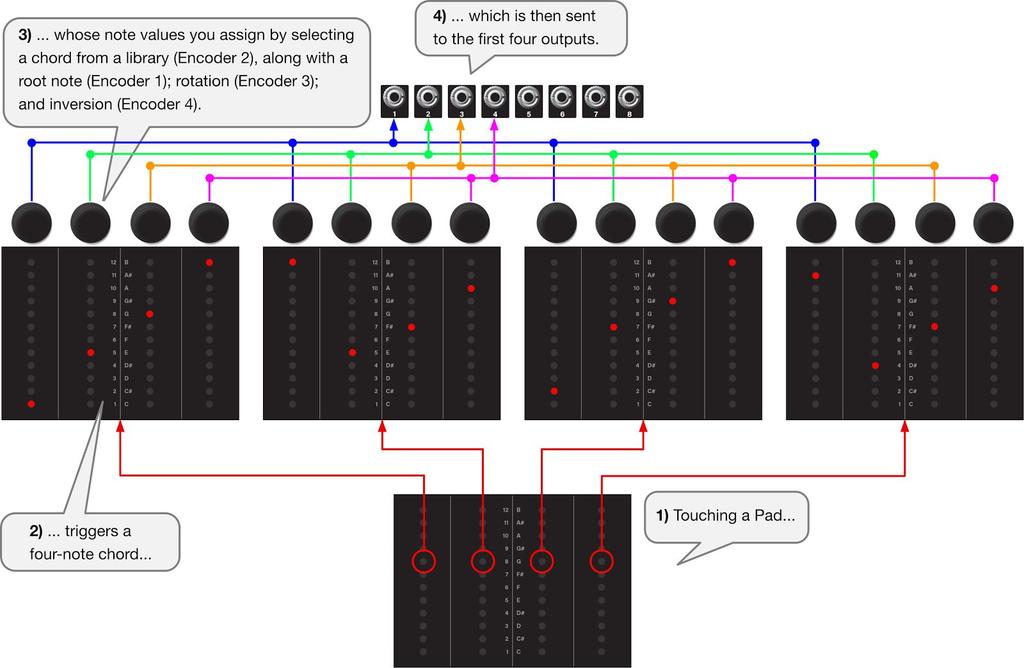
38 Mode 8: Chord Mode Press the white Mode Select button and rotate any of the four encoders to select Mode 8, which occurs when the row of Level LEDs light next to Level Label 8. Press the white Mode Select button again (or press any encoder) to exit mode selection. Chord Mode stores a unique 4-note chord for each of the four pads, which you select from a built-in Chord Library. Touching a pad transmits the four notes to the first four outputs, enabling you to play one-finger chords (if you use multiple oscillators). Pads also output both a trigger and a gate signal, and they respond to both position and pressure, giving you expressive CV control over anything you want (such as a VCA level or filter frequency). Root note changes, inversions and rotations are just an encoder turn away. Page 37
39 Using Chord Mode In Chord mode, the pads serve two purposes: As a performance controller: Touching Pad 1 sends four memorized notes (a chord) to Outputs 1-4; touching Pad 2 sends a different set of notes out the same Outputs; etc. As a note/chord display: When you touch Pad 1, the notes it sends to Outs 1-4 are displayed on Pads 1-4. When you touch Pad 2, the notes it sends to Outs 1-4 are then displayed on the four pads. The notes within each chord are selected from a built-in Chord Library and assigned root, rotation and inversion features as described below: Chord Selection Define a chord for each pad by selecting it from the built-in Chord Library, and alter the root note, inversion and chord rotations using the encoders: 1. Touch a pad to select which of the four chords you want to define. All the ladder LEDs beneath the pad s surface light dimly to indicate that it s the active and editable pad. 2. Rotate Encoder 1 to set the root note of the chord, as it appears on Out 1. If you push Encoder 1 while rotating it, you will change the root s octave. 3. Rotate encoder 2 to scroll through different chords in Tetrapad s library. Selecting different chords changes the note assignments for Outs 2, 3 and 4. Tetrapad s internal library contains 12 chords, which encoder 2 rotates through continuously, and which are shown in the table on the following page. 4. Rotate encoder 3 to rotate the output assignment of each note. With each clockwise rotation, the output assignments shift to the right by 1. So if you rotate Encoder 3 one turn CW, the root note moves to Out 2 and all the other output assignments shift to the right by 1, with note 4 now appearing at Out 1. NOTE: The brightest of the four blue Output Status LEDs indicates which output is currently assigned to the root note. So, as you rotate encoder 3, the bright blue Output Status LED will rotate among the outputs as the chord rotates. 5. Rotate encoder 4 to invert the chord. Clockwise rotation of Encoder 4 inverts the chord upward; Counterclockwise rotation inverts the chord downward. Page 38
40 For example, one CW turn transposes the root note up 1 octave; a second CW turn transposes the second note up 1 octave, and so on. Similarly, one CCW turn transposes the fourth note down 1 octave; etc. 6. Touch each of the remaining three pads and repeat steps 3-6 to define 4-note chords for each of the four pads. Chord Name Unison Major w/octave Minor w/octave Major 7th Minor 7th Dominant 7th Diminished 7th Half-Diminished 7th Minor Major 7th Augmented Major 7th Augmented 7th Diminished Major 7th Dominant 7th flat 5th Intervals 0, 0, 0, 0 0, 4, 7, 12 0, 3, 7, 12 0, 4, 7, 11 0, 3, 7, 10 0, 4, 7, 10 0, 3, 6, 9 0, 3, 6, 10 0, 3, 7, 11 0, 4, 8, 11 0, 4, 8, 10 0, 3, 6, 11 0, 4, 6, 10 Page 39
41 Slew Between Chords Tetrapad gives you the ability to slew between chord changes. To do so, press the red Shift button and continue holding it while turning Encoder 1. Clockwise turns increase the time it takes to move from one chord to another (up to a maximum of about 30 sec for a 10 octave glide). Counterclockwise turns decrease the amount of time it takes to move from one chord to another (down to instantaneous ). Slew times are indicated by a red Pad Status LED above each fader with an LED glowing increasingly brighter as the slew gets longer. Note that slew time is a global setting within Chord Mode, meaning the rate of change affects all chords equally. Performing in Chord Mode Once you ve assigned chords to all four pads, you re ready to perform. 1. Route Tetrapad s first four outputs to four different oscillators. 2. Press one of the four pads to send a four-note chord to those four oscillators. 3. Press another pad to send another four-note chord, etc. 4. Chord mode also features gate, trigger, position and pressure outputs. These are assigned as follows: Out 5: Vertical Position of whichever pad you re currently touching. Brightness of green Output Status LED indicates absolute level. Out 6: Pressure of whichever pad you re currently touching. Brightness of red Output Status LED indicates absolute level. Out 7: Trigger value sent any time you touch any pad. The red Output Status LED turns on, then immediately turns off when a pad is touched indicating a trigger output. Out 8: Gate signal sent any time you touch any pad. The red Output Status LED turns on and stays on as long as a pad is touched indicating a gate output. 5. Route these last four outputs to envelopes or control voltage inputs on other modules to enable more expressive and organic performances. Page 40
42 Page 41
 to exit mode selection. Custom Chord Mode stores a unique 4-note chord for each of the four pads.")
43 Mode 9: Custom Chord Mode Press the white Mode Select button and rotate any of the four encoders to select Mode 9, which occurs when the row of Level LEDs light next to Level Label 9. Press the white Mode Select button again (or press any encoder) to exit mode selection. Custom Chord Mode stores a unique 4-note chord for each of the four pads. Touching a pad transmits the four notes to the first four outputs, enabling you to play one-finger chords (if you use multiple oscillators). Pads also output both a trigger and a gate signal, and they respond to both position and pressure, giving you expressive CV control over anything you want (such as a VCA level or filter frequency). Unlike Mode 4, Custom Chord Mode lets you define your own chord patterns, allowing for harmonic structures beyond those included in Mode 4 s Chord Library. Page 42
44 Using Custom Chord Mode In Custom Chord mode, the pads serve two purposes: As a performance controller: Touching Pad 1 sends four memorized notes (a chord) out of outputs 1-4; touching Pad 2 sends a different set of notes out the same outputs; etc. As a note/chord display: When you touch Pad 1, the notes it sends to Outs 1-4 are displayed on Pads 1-4. When you touch Pad 2, the notes it sends to Outs 1-4 are then displayed on the four pads. The notes within each chord are edited directly by turning the four encoders, as described below. Chord Entry 1. Touch one of the four pads to select it for chord editing. All the ladder LEDs beneath the pad s surface light dimly to indicate that it s the active and editable pad. 2. Rotate Encoder 1 to set the chord s root note, which is sent to Out 1. Rotate encoders 2-4 to set the interval values, which Tetrapad sends to Outputs 2-4. Beneath the surface of each pad is a brightly lit LED, indicating the note value assigned to the corresponding Output number (as seen with the Level Label in the center of the four pads). That is, the bright LED beneath Pad 1 shows the note sent to Out 1; the bright LED beneath Pad 2 shows the note sent to Out 2; etc. 3. Press & turn an encoder to increment or decrement its note assignment by octave. The Pad Status LED glows an increasingly brighter green for each octave higher than default. It glows increasingly brighter red for each octave lower than the default. Notes can be set over a 10 octave range. 4. To transpose the chord, simply rotate Encoder 1 to change the root note, shifting all four Outs up/down accordingly. Similarly, push-turning Encoder 1 transposes the entire chord up/down by octave. 5. Press an encoder if you want to reset its output to C (0V). Pressing Encoder 1 transposes the entire chord to the root of C. 6. Touch each of the remaining three pads and repeat steps 2-5 to define 4-note chords for each of the four pads. Page 43
45 Slew Between Chords Tetrapad gives you the ability to slew between chord changes. To do so, press the red Shift button and continue holding it while turning Encoder 1. Clockwise turns increase the time it takes to move from one chord to another (up to a maximum of about 30 sec for a 10 octave glide). Counterclockwise turns decrease the amount of time it takes to move from one chord to another (down to instantaneous ). Slew times are indicated by a red Pad Status LED above each fader with an LED glowing increasingly brighter as the slew gets longer. Note that slew time is a global setting within Chord Mode, meaning the rate of change affects all chords equally. Performing in Custom Chord Mode Once you ve assigned chords to all four pads, you re ready to perform. 1. Route Tetrapad s first four outputs to four different oscillators. 2. Press one of the four pads to send a four-note chord to those four oscillators. 3. Press another pad to send another four-note chord, etc. 4. Chord mode also features gate, trigger, position and pressure outputs. These are assigned as follows: Out 5: Vertical Position of whichever pad you re currently touching. Brightness of green Output Status LED indicates absolute level. Out 6: Pressure of whichever pad you re currently touching. Brightness of red Output Status LED indicates absolute level. Out 7: Trigger value sent any time you touch any pad. The red Output Status LED turns on, then immediately turns off when a pad is touched indicating a trigger output. Out 8: Gate signal sent any time you touch any pad. The red Output Status LED turns on and stays on as long as a pad is touched indicating a gate output. 5. Route these last four outputs to envelopes or control voltage inputs on other modules to enable more expressive and organic performances. Page 44
46 By way of example, look at the following illustration. We see that touching Pad 1 sends C-E-G-B to Outputs 1-4; touching Pad 2 sends a B-E-F#-A to Outputs 1-4; Pad 3 sends C#-F#-G#-B to Outs 1-4; and Pad 4 sends A#-D#-F#-A to Outs 1-4: Page 45
 to exit mode selection.")
47 Mode 12: Global Configuration Press the white Mode Select button and rotate any of the four encoders to select Mode 12, which occurs when the row of Level LEDs light next to Level Label 12. Press the white Mode Select button again (or press any encoder) to exit mode selection. In Global Configuration Mode, each pad has a corresponding pair of active outputs, so you can test the effect of your settings while still in Configuration Mode. Each pad s position CV appears at its odd numbered out, and its pressure CV appears at the even. Page 46

48 Using Global Configuration Mode To adjust the pressure response curve: 1. Rotate Encoder 1 until the first LED is lit beneath the surface of Pad 1. The first LED indicates that you re editing Parameter #1, which is the Pressure Response Curve parameter. 2. Rotate Encoder 2 to select the desired pressure response curve. There are four options, numbered 1-4 (as indicated by the LEDs beneath the pad s surface). These are: 1: Square (factory default); 2: Linear; 3: Exponential; and 4: Logarithmic. These are indicated graphically in the following illustration: Page 47
49 To adjust the pressure filter: 1. Rotate Encoder 1 until the second LED is lit beneath the surface of Pad 1. The second LED indicates that you re editing Parameter #2, which is the Pressure Filter parameter. 2. Rotate Encoder 2 to select the desired filter. There are 12 filtration levels, numbered 1-12 (as indicated by the LEDs beneath the pad s surface). Higher numbers are more sensitive to pressure variation than lower numbers. Tetrapad ships with a default level of 7. To adjust the touch sensitivity: 1. Rotate Encoder 1 until the third LED is lit beneath the surface of Pad 1. The third LED indicates that you re editing Parameter #3, which is the Touch Sensitivity parameter. 2. Rotate Encoder 2 to select the desired touch sensitivity. There are 12 sensitivity levels, numbered 1-12 (as indicated by the LEDs beneath the pad s surface). Higher numbers are more sensitive to the touch of your finger but slightly less sensitive to its position, while lower numbers are less sensitive to touch, but more sensitive to position. Touch sensitivity has the most obvious effect in highly-reactive modes, like Mode 1: Faders Mode, where the way in which you touch a fader has the most effect on the CV values it transmits. Tetrapad ships with a default value level of 7. Page 48
 the current firmware version using the Level LEDs embedded beneath each of the four")
50 Firmware Version Display When you first power up Tetrapad, all its LEDs blink rhythmically for a few seconds. After the light show completes and immediately before the module is ready to use, it displays (for about 1 second) the current firmware version using the Level LEDs embedded beneath each of the four pads. Specifically, the four pads represent version xx.yy as follows: For example, version 1.00 would appear as shown on the left, and version 3.14 would appear as shown on the right: Page 49
Shifty Manual v1.00. Shifty. Voice Allocator / Hocketing Controller / Analog Shift Register
 Shifty Manual v1.00 Shifty Voice Allocator / Hocketing Controller / Analog Shift Register Table of Contents Table of Contents Overview Features Installation Before Your Start Installing Your Module Front
Shifty Manual. Shifty. Voice Allocator Hocketing Controller Analog Shift Register Sequential/Manual Switch. Manual Revision:
 Shifty Voice Allocator Hocketing Controller Analog Shift Register Sequential/Manual Switch Manual Revision: 2018.10.14 Table of Contents Table of Contents Compliance Installation Installing Your Module
Intelligent Quantizer and Interval Generator
 µscale Intelligent Quantizer and Interval Generator Manual Revision: 2018.02.16 Table of Contents Table of Contents Overview Features Installation Before Your Start Installing Your Module Front Panel Controls
Noise Tools 1U Manual. Noise Tools 1U. Clock, Random Pulse, Analog Noise, Sample & Hold, and Slew. Manual Revision:
 Noise Tools 1U Clock, Random Pulse, Analog Noise, Sample & Hold, and Slew Manual Revision: 2018.05.16 Table of Contents Table of Contents Overview Installation Before Your Start Installing Your Module
Noise Tools 1U Manual. Noise Tools 1U. Clock, Random Pulse, Analog Noise, Sample & Hold, and Slew. Manual Revision:
 Noise Tools 1U Clock, Random Pulse, Analog Noise, Sample & Hold, and Slew Manual Revision: 2018.09.13 Table of Contents Table of Contents Compliance Installation Before Your Start Installing Your Module
Audio Interface II Manual. Audio Interface II. Eurorack <-> Line Level Audio Interface. Manual Revision: 1.0
 Audio Interface II Eurorack Line Level Audio Interface Manual Revision: 1.0 Overview The Audio Interface II allows you to interface your Eurorack modular system to the pro balanced line level world
Audio Interface II Manual. Audio Interface II. Eurorack <-> Line Level Audio Interface. Manual Revision:
 Audio Interface II Eurorack Line Level Audio Interface Manual Revision: 2018.09.13 Table of Contents Table of Contents Compliance Installation Installing Your Module Overview Features Front Panel Controls
ALGORHYTHM. User Manual. Version 1.0
 !! ALGORHYTHM User Manual Version 1.0 ALGORHYTHM Algorhythm is an eight-step pulse sequencer for the Eurorack modular synth format. The interface provides realtime programming of patterns and sequencer
User Guide. Version 2.0.0
 II User Guide Version 2.0.0 Contents Introduction... 3 What s New in Step Note Recorder II?... 3 Getting Started... 4 The Front Panel... 5 The Sequence... 5 The Piano Roll... 6 The Data Lane... 7 Velocity...
Pressure Points. v. 2.5
 Pressure Points v. 2.5 2 Pressure Points FCC-------------------------------------------------------------------3 Limited Warranty ----------------------------------------------------4 Installation ----------------------------------------------------5
Quad Clock Distributor (QCD) from 4ms Company
 from 4ms Company") Quad Clock Distributor (QCD) from 4ms Company Eurorack Module User Manual v1.0 (2013-12-09) The Quad Clock Distributor (QCD) from 4ms Company is a four channel Voltage Controlled Clock Divider/Multiplier
Quad Clock Distributor (QCD) from 4ms Company Eurorack Module User Manual v1.0 (2013-12-09) The Quad Clock Distributor (QCD) from 4ms Company is a four channel Voltage Controlled Clock Divider/Multiplier
QUAD LFO MANUAL V SE 14TH AVENUE PORTLAND OR USA
 www.malekkoheavyindustry.com 814 SE 14TH AVENUE PORTLAND OR 97214 USA TABLE OF CONTENTS SPECIFICATIONS 1 INSTALLATION 2 DESCRIPTION 3 CONTROLS 4-6 USING QUAD LFO WITH VARIGATE 8+ AND VARIGATE 4+ 7 WARRANTY
randomrhythm Bedienungsanleitung User Guide
 randomrhythm Bedienungsanleitung User Guide EN Foreword Whether random really exists or is just an illusion, shall be discussed by philosophers and mathematicians. At VERMONA, we found a possibility to
Written by Jered Flickinger Copyright 2019 Future Retro
 Written by Jered Flickinger Copyright 2019 Future Retro www.future-retro.com 2 TABLE OF CONTENTS Page 4 - Overview Page 5 Controls Page 6 Inputs and Outputs Page 7 MIDI Page 8 Jumper Settings Page 9 Standalone
R H Y T H M G E N E R A T O R. User Guide. Version 1.3.0
 R H Y T H M G E N E R A T O R User Guide Version 1.3.0 Contents Introduction... 3 Getting Started... 4 Loading a Combinator Patch... 4 The Front Panel... 5 The Display... 5 Pattern... 6 Sync... 7 Gates...
Sequencer 1 User s Guide
 Sequencer 1 User s Guide Audio Damage, Inc. For Firmware Version 1.5.0 22 December 2016 The information in this document is subject to change without notice and does not represent a commitment on the part
fxbox User Manual P. 1 Fxbox User Manual
 fxbox User Manual P. 1 Fxbox User Manual OVERVIEW 3 THE MICROSD CARD 4 WORKING WITH EFFECTS 4 MOMENTARILY APPLY AN EFFECT 4 TRIGGER AN EFFECT VIA CONTROL VOLTAGE SIGNAL 4 TRIGGER AN EFFECT VIA MIDI INPUT
Plog rev 1.0 MANUAL Overview
 Overview The Intellijel Plog is a voltage controllable digital logic device designed for musical applications. It is primarily intended to create controllable patterns from gate/ pulse sources like clocks
Show Designer 3. Software Revision 1.15
 Show Designer 3 Software Revision 1.15 OVERVIEW... 1 REAR PANEL CONNECTIONS... 1 TOP PANEL... 2 MENU AND SETUP FUNCTIONS... 3 CHOOSE FIXTURES... 3 PATCH FIXTURES... 3 PATCH CONVENTIONAL DIMMERS... 4 COPY
Vocal Processor. Operating instructions. English
 Vocal Processor Operating instructions English Contents VOCAL PROCESSOR About the Vocal Processor 1 The new features offered by the Vocal Processor 1 Loading the Operating System 2 Connections 3 Activate
Eventide Inc. One Alsan Way Little Ferry, NJ
 Copyright 2017, Eventide Inc. P/N 141298, Rev 3 Eventide is a registered trademark of Eventide Inc. AAX and Pro Tools are trademarks of Avid Technology. Names and logos are used with permission. Audio
4ms Quad Pingable LFO
 4ms Quad Pingable LFO Eurorack Module User Manual v2013-04-04 (pre-release) The Quad Pingable LFO (QPLFO) from 4ms Company is a compact, playable quad modulation source of four independent and identical
Oberkorn User Manual. Analogue Sequencer. Analogue Solutions
 Oberkorn User Manual Analogue Sequencer Analogue Solutions CONTENTS What is an analogue sequencer?... 4 That s all very well (and technical) but what would I use it for?... 4 ABOUT THIS MANUAL AND ABOUT
VARIGATE 4+ MANUAL V.1
 www.malekkoheavyindustry.com 814 SE 14TH AVENUE PORTLAND OR 97214 USA TABLE OF CONTENTS SPECIFICATIONS 1 INSTALLATION 2 DESCRIPTION 3 OVERVIEW 4-5 PROGRAMMING GATES PER STEP 6 PROGRAMMING CV/NOTES PER
NoteMix Player Note Mixer/Shifter/Splitter/Filter with Snapshot Morphing Rack Extension for Propellerhead Reason
 NoteMix Player Note Mixer/Shifter/Splitter/Filter with Snapshot Morphing Rack Extension for Propellerhead Reason USER MANUAL version 1.0.0 NoteMix User Manual www.retouchcontrol.com Page 1 of 26 Table
Reference Manual. Using this Reference Manual...2. Edit Mode...2. Changing detailed operator settings...3
 Reference Manual EN Using this Reference Manual...2 Edit Mode...2 Changing detailed operator settings...3 Operator Settings screen (page 1)...3 Operator Settings screen (page 2)...4 KSC (Keyboard Scaling)
NAVIGATOR OWNER S MANUAL
 OWNER S MANUAL UNCHARTED WATERS, NEW HORIZONS Making shapes spin and move is notoriously difficult for pattern synthesis based only on oscillators synchronized to horizontal and vertical frequency ranges.
ADE-32 OCTOCONTROLLER
 ADE-32 OCTOCONTROLLER Control, Modulation, Triggering and Pattern module with 12 Output Types individually assignable to 8 simultaneous Outputs. USER GUIDE 2016 Abstract Data Ltd. http://www.abstractdata.biz
multitrack sequencer USER GUIDE Social Entropy Electronic Music Instruments
 multitrack sequencer Social Entropy Electronic Music Instruments IMPORTANT SAFETY AND MAINTENANCE INSTRUCTIONS TABLE OF CONTENTS BACKGROUND... 1 CONCEPTS... 2 DIAGRAM CONVENTIONS... 3 THE BASICS WHAT
Dave Jones Design Phone: (607) Lake St., Owego, NY USA
 Lake St., Owego, NY USA") Manual v1.00a June 1, 2016 for firmware vers. 2.00 Dave Jones Design Phone: (607) 687-5740 34 Lake St., Owego, NY 13827 USA www.jonesvideo.com O Tool Plus - User Manual Main mode NOTE: New modules are
Manual v1.00a June 1, 2016 for firmware vers. 2.00 Dave Jones Design Phone: (607) 687-5740 34 Lake St., Owego, NY 13827 USA www.jonesvideo.com O Tool Plus - User Manual Main mode NOTE: New modules are
QUAD ENVELOPE MANUAL V.1
 www.malekkoheavyindustry.com 814 SE 14TH AVENUE PORTLAND OR 97214 USA TABLE OF CONTENTS SPECIFICATIONS 1 INSTALLATION 2 DESCRIPTION 3 CONTROLS 4-6 MEASUREMENTS 7 USING QUAD ENVELOPE WITH VARIGATE 8+ AND
MantaMate User Manual. Snyderphonics
 MantaMate User Manual Snyderphonics Version 0.7, July 30, 2017 Contents Preface 1 Setting up the MantaMate 1 1.1 Connecting Power......................... 1 1.2 Output Voltage Range Jumper..................
Table of Contents: ECHOPHON
 v2.6 Table of Contents: 2 ECHOPHON FCC -----------------------------------------------------3 Limited Warranty ----------------------------------------4 Installation --------------------------------------------------5
American DJ. Show Designer. Software Revision 2.08
 American DJ Show Designer Software Revision 2.08 American DJ 4295 Charter Street Los Angeles, CA 90058 USA E-mail: support@ameriandj.com Web: www.americandj.com OVERVIEW Show Designer is a new lighting
Study Guide. Solutions to Selected Exercises. Foundations of Music and Musicianship with CD-ROM. 2nd Edition. David Damschroder
 Study Guide Solutions to Selected Exercises Foundations of Music and Musicianship with CD-ROM 2nd Edition by David Damschroder Solutions to Selected Exercises 1 CHAPTER 1 P1-4 Do exercises a-c. Remember
// K4815 // Pattern Generator. User Manual. Hardware Version D-F Firmware Version 1.2x February 5, 2013 Kilpatrick Audio
 // K4815 // Pattern Generator Kilpatrick Audio // K4815 // Pattern Generator 2p Introduction Welcome to the wonderful world of the K4815 Pattern Generator. The K4815 is a unique and flexible way of generating
Limited WARRANTY: Make Noise implies and accepts no responsibility for harm to person or apparatus caused through operation of this product.
 v2.4 1 BRAINS Limited Warranty: ----------------------------------------------------2 Installation: --------------------------------------------------3 Jumpers and Cable Connections: --------------------------------4
Synthesis Technology E102 Quad Temporal Shifter User Guide Version 1.0. Dec
 Synthesis Technology E102 Quad Temporal Shifter User Guide Version 1.0 Dec. 2014 www.synthtech.com/euro/e102 OVERVIEW The Synthesis Technology E102 is a digital implementation of the classic Analog Shift
STX Stairs lighting controller.
 Stairs lighting controller STX-1795 The STX-1795 controller serves for a dynamic control of the lighting of stairs. The lighting is switched on for consecutive steps, upwards or downwards, depending on
Revision 1.2d
 Specifications subject to change without notice 0 of 16 Universal Encoder Checker Universal Encoder Checker...1 Description...2 Components...2 Encoder Checker and Adapter Connections...2 Warning: High
Limited WARRANTY: Make Noise implies and accepts no responsibility for harm to person or apparatus caused through operation of this product.
 v2.5 2 BRAINS Limited Warranty ----------------------------------------------------3 Installation --------------------------------------------------4 Jumpers and Cable Connections --------------------------------5
TL5024 MEMORY LIGHTING CONSOLE OWNERS MANUAL. Version 1.01
 TL5024 MEMORY LIGHTING CONSOLE OWNERS MANUAL Version 1.01 09/22/2017 Page 2 of 14 SPECIFICATIONS Total channels Operating modes Scene memory Chase 12 or 24 depending on mode 12 channels x 2 manual scenes
TF5 / TF3 / TF1 DIGITAL MIXING CONSOLE. TF StageMix User's Guide
 TF5 / TF3 / TF1 DIGITAL MIXING CONSOLE EN Note The software and this document are the exclusive copyrights of Yamaha Corporation. Copying or modifying the software or reproduction of this document, by
Spectral Multiband Resonator from 4ms Company Eurorack Module User Manual v1.1 (firmware v5: December 2016)
") Spectral Multiband Resonator from 4ms Company Eurorack Module User Manual v1.1 (firmware v5: December 2016) The Spectral Multiband Resonator from 4ms Company is a versatile resonant filter with six bandpass
Spectral Multiband Resonator from 4ms Company Eurorack Module User Manual v1.1 (firmware v5: December 2016) The Spectral Multiband Resonator from 4ms Company is a versatile resonant filter with six bandpass
Edit Menu. To Change a Parameter Place the cursor below the parameter field. Rotate the Data Entry Control to change the parameter value.
 The Edit Menu contains four layers of preset parameters that you can modify and then save as preset information in one of the user preset locations. There are four instrument layers in the Edit menu. See
Modcan Touch Sequencer Manual
 Modcan Touch Sequencer Manual Normal 12V operation Only if +5V rail is available Screen Contrast Adjustment Remove big resistor if using with PSU with 5V rail Jumper TOP VEIW +5V (optional) +12V } GND
THE FROG SERIES OPERATING MANUAL
 THE FROG SERIES OPERATING MANUAL THE FROG SERIES OPERATING MANUAL If a portable or temporary three phase mains supply is used to power this desk, we recommend that the desk mains plug is removed before
Polyend Poly Polyphonic MIDI to CV Converter User Manual
 Polyend Poly Polyphonic MIDI to CV Converter User Manual Made in Poland polyend.com Polyend Poly Polyphonic MIDI to CV Converter in the Eurorack format Poly is probably the easiest entry point for exploring
User Guide Version 1.1.0
 obotic ean C R E A T I V E User Guide Version 1.1.0 Contents Introduction... 3 Getting Started... 4 Loading a Combinator Patch... 5 The Front Panel... 6 On/Off... 6 The Display... 6 Reset... 7 Keys...
OPERATING MANUAL. including
 OPERATING MANUAL including & If a portable or temporary three phase mains supply is used to power this desk, we recommend that the desk mains plug is removed before connecting or disconnecting the supply.
Spectral Multiband Resonator from 4ms Company Eurorack Module User Manual v1.0 (July 2015)
") Spectral Multiband Resonator from 4ms Company Eurorack Module User Manual v1.0 (July 2015) The Spectral Multiband Resonator from 4ms Company is a versatile resonant filter with six bandpass resonators/filters
Spectral Multiband Resonator from 4ms Company Eurorack Module User Manual v1.0 (July 2015) The Spectral Multiband Resonator from 4ms Company is a versatile resonant filter with six bandpass resonators/filters
Reason Overview3. Reason Overview
 Reason Overview3 In this chapter we ll take a quick look around the Reason interface and get an overview of what working in Reason will be like. If Reason is your first music studio, chances are the interface
Please contact with any questions, needs & comments... otherwise go MAKE NOISE.
 soundhack ECHOPHON Limited WARRANTY: Make Noise warrants this product to be free of defects in materials or construction for a period of two years from the date of manufacture. Malfunction resulting from
5U Oakley Modular Series
 Oakley Sound Systems 5U Oakley Modular Series VC-LFO Low Frequency Oscillator PCB Issue 2 User Manual V2.0.04 Tony Allgood B.Eng PGCE Oakley Sound Systems CARLISLE United Kingdom The suggested panel layout
TF5 / TF3 / TF1 DIGITAL MIXING CONSOLE. TF Editor User Guide
 TF5 / TF3 / TF1 DIGITAL MIXING CONSOLE EN Special notices Copyrights of the software and this document are the exclusive property of Yamaha Corporation. Copying or modifying the software or reproduction
Background. About automation subtracks
 16 Background Cubase provides very comprehensive automation features. Virtually every mixer and effect parameter can be automated. There are two main methods you can use to automate parameter settings:
GUIDE TO ASSEMBLY OF ERICA SYNTHS DELAY MODULE
 If you are reading this, most probably, you are about to build Erica Synths DIY DELAY module. The module is 4mm deep, skiff friendly, has solid mechanical construction and doesn t require wiring. Erica
TEMPI FCC: Limited Warranty:
 v2.5 1 TEMPI FCC: ------------------------------------------------------------------2 Limited Warranty: -------------------------------------------------3 Installation: ----------------------------------------------------------4
KNX Dimmer RGBW - User Manual
 KNX Dimmer RGBW - User Manual Item No.: LC-013-004 1. Product Description With the KNX Dimmer RGBW it is possible to control of RGBW, WW-CW LED or 4 independent channels with integrated KNX BCU. Simple
Inspire Station. Programming Guide. Software Version 3.0. Rev A
 Inspire Station Programming Guide Software Version 3.0 Rev A Copyright 2016 Electronic Theatre Controls, Inc. All rights reserved. Product information and specifications subject to change. Part Number:
Rebis Audio Ltd. RA226 Digital Sampler User Guide
 Rebis Audio Ltd. RA226 Digital Sampler User Guide CONTENTS Page Caution 2 Powering Up 2 Controls 3, 4 Detailed Description Input Level Set 5 Recording 5 Sampling 5 Multiple Samples 6 Editing 6 Playback
DMX-LINK QUICK OPERATION
 DMX-LINK QUICK OPERATION RESETTING THE CURRENT PATCH TO A ONE-TO-ONE OR ZERO PATCH The current Patch List may be initialised as a One-to-One or Zero patch as follows: 1. Ensure the Record LED is on. If
Description. Never run out of envelopes again.
 Contour Description Never run out of envelopes again. Contour is a quad envelope generator. Each channel has looping, CV over attack and decay, as well as unique chaining capabilities. This makes for the
oberkorn3 analogue sequencer user manual analogue sequencer user manual ANALOGUE SOLUTIONS oberkorn mkiii e&oe (c)
") oberkorn3 analogue sequencer user manual analogue sequencer user manual ANALOGUE SOLUTIONS oberkorn mkiii e&oe (c) 10-2006 1 Contents Intro - OBERKORN - Professional Analogue Sequencer...4 About Analogue
oberkorn3 analogue sequencer user manual analogue sequencer user manual ANALOGUE SOLUTIONS oberkorn mkiii e&oe (c) 10-2006 1 Contents Intro - OBERKORN - Professional Analogue Sequencer...4 About Analogue
Chapter 40: MIDI Tool
 MIDI Tool 40-1 40: MIDI Tool MIDI Tool What it does This tool lets you edit the actual MIDI data that Finale stores with your music key velocities (how hard each note was struck), Start and Stop Times
SCENEMASTER 3F QUICK OPERATION
 SETTING PRESET MODE SCENEMASTER 3F QUICK OPERATION 1. Hold [RECORD], and press [CHNS] (above the Channels Master) to set Scenes, Dual, or Wide mode. WIDE MODE OPERATION In Wide mode, both CHANNELS and
DAGON Company Leszno Jackowskiego 24 Street tel DAGON Lighting series SPL-3
 DAGON Company 64-100 Leszno Jackowskiego 24 Street tel. +48 664-092-493 dagon@iadagon.pl www.dagonlighting.com DAGON Lighting series SPL-3 DIODES and RGB LED STRIP DRIVER works alone or controlled by:
Smart Hawk Firing System User s Manual
 Firmware Version 3.09 Page 1 of 57 Table of Contents A reminder on the safe use of Electronic Pyrotechnic Firing Systems... 4 Description... 5 Common Features of the Smart Hawk Panel... 6 Features of the
16 Stage Bi-Directional LED Sequencer
 16 Stage Bi-Directional LED Sequencer The bi-directional sequencer uses a 4 bit binary up/down counter (CD4516) and two "1 of 8 line decoders" (74HC138 or 74HCT138) to generate the popular "Night Rider"
ADSR AMP. ENVELOPE. Moog Music s Guide To Analog Synthesized Percussion. The First Step COMMON VOLUME ENVELOPES
 Moog Music s Guide To Analog Synthesized Percussion Creating tones for reproducing the family of instruments in which sound arises from the striking of materials with sticks, hammers, or the hands. The
LS1lightstrip User s Manual. Introduction Care and feeding Specifications. soundmachines user manual 1 LS1lightstrip
 User s Manual Introduction Care and feeding Specifications soundmachines user manual 1 Introduction The is a capacitive slider that will generate CV and GATE signals along with the movement of your finger
// K4815 // Pattern Generator. User Manual. Hardware Version D/E Firmware Version 1.1x February 16, 2011 Kilpatrick Audio
 // K4815 // Pattern Generator Kilpatrick Audio // K4815 // Pattern Generator 2p Introduction Welcome to the wonderful world of the K4815 Pattern Generator. The K4815 is a unique and flexible way of generating
Operating Instructions
 CNTX Contrast sensor Operating Instructions CAUTIONS AND WARNINGS SET-UP DISTANCE ADJUSTMENT: As a general rule, the sensor should be fixed at a 15 to 20 angle from directly perpendicular to the target
VERSION 2.A 10/21/1999. Lightronics Inc. 509 Central Drive, Virginia Beach, VA TEL
 7/ 0(025< /,*+7,1*&21752/ &2162/( 2:1(56Ã0$18$/ VERSION 2.A 10/21/1999 Contents DESCRIPTION OF CONTROLS 3 OPERATION 4 USING THE MENU SYSTEM 5 MENU FUNCTIONS 5 RECORDING SCENES 7 USING SCENES 8 RECORDING
Proper installation of included power cable on module. Please note the RED BAND.
 PHONOGENE 1 Installation: The Make Noise Phonogene is an electronic signal processor/ generator requiring 70mA of +/-12V regulated power and properly formatted distribution receptacle to operate. It is
V4.7 Software Quick Start Guide
 V4.7 Software Quick Start Guide INTRODUCTION TO V4.7 The 4.7 software update for the Vi Series includes a major update to the functionality of the Vi4 console in particular, bringing a new level of power
Using Sliders with the 4201-B Lighting Controller Application Note June 26, 2008
 Using Sliders with the 4201-B Lighting Controller Application Note June 26, 2008 This application note will discuss ways of using potentiometers (sliders or normal rotary volume control type) with the
Original Marketing Material circa 1976
 Original Marketing Material circa 1976 3 Introduction The H910 Harmonizer was pro audio s first digital audio effects unit. The ability to manipulate time, pitch and feedback with just a few knobs and
RE-303 CPU. SONIC-POTIONS!!! PRELIMINARY DRAFT!!! v WORK IN PROGRESS
 RE-303 CPU SONIC-POTIONS!!! PRELIMINARY DRAFT!!! v 0.911 WORK IN PROGRESS Intro... 3 Quickstart... 3 The random way... 3 The manual way...3 Control scheme... 4 Pattern Write Mode... 4 Auto Exit... 4 Normal
Element 78 MPE-200. by Summit Audio. Guide To Operations. for software version 1.23
 Element 78 MPE-200 by Summit Audio Guide To Operations for software version 1.23 TABLE OF CONTENTS IMPORTANT SAFETY AND GROUNDING INSTRUCTIONS COVER 1. UNPACKING AND CONNECTING...3 AUDIO CONNECTIONS...4
Spiratone FCC: Limited Warranty:
 SpirA tone v. 2.3 1 Spiratone FCC: -------------------------------------------------------------------2 Limited Warranty: ----------------------------------------------------3 Installation: ---------------------------------------------------------4
MCV24 MIDI-CV/GATE/SYNC INTERFACE
 DOEPFER MCV24 MIDI-CV/GATE/SYNC INTERFACE Preliminary English owners manual written by EMIS (C) 1999 Revision 1.0 July 1999 Controls and connections Frontpanel 1 2 3 4 5 6 7 8 9 10 11 1 32 character backlit
XYNTHESIZR User Guide 1.5
 XYNTHESIZR User Guide 1.5 Overview Main Screen Sequencer Grid Bottom Panel Control Panel Synth Panel OSC1 & OSC2 Amp Envelope LFO1 & LFO2 Filter Filter Envelope Reverb Pan Delay SEQ Panel Sequencer Key
Cedits bim bum bam. OOG series
 Cedits bim bum bam OOG series Manual Version 1.0 (10/2017) Products Version 1.0 (10/2017) www.k-devices.com - support@k-devices.com K-Devices, 2017. All rights reserved. INDEX 1. OOG SERIES 4 2. INSTALLATION
Dual Looping Delay from 4ms Company Eurorack Module User Manual 1.1c (2017-January-11) Firmware version 5
 Firmware version 5") Dual Looping Delay from 4ms Company Eurorack Module User Manual 1.1c (2017-January-11) Firmware version 5 The Dual Looping Delay (DLD), designed by 4ms Company and Gary Hall, is an advanced audio processor
Dual Looping Delay from 4ms Company Eurorack Module User Manual 1.1c (2017-January-11) Firmware version 5 The Dual Looping Delay (DLD), designed by 4ms Company and Gary Hall, is an advanced audio processor
The Complete Guide to Music Technology using Cubase Sample Chapter
 The Complete Guide to Music Technology using Cubase Sample Chapter This is a sample of part of a chapter from 'The Complete Guide to Music Technology', ISBN 978-0-244-05314-7, available from lulu.com.
Atlas Drop In Decoder
 TCS DCC decoders provide the ultimate in control. This decoder is in # A1 Atlas Drop In Decoder 1.3 amp continuous, 2.0 amp peak motor drive plus four 100 ma function outputs Dither creates the ultimate
SNG-2150C User s Guide
 SNG-2150C User s Guide Avcom of Virginia SNG-2150C User s Guide 7730 Whitepine Road Revision 001 Richmond, VA 23237 USA GENERAL SAFETY If one or more components of your earth station are connected to 120
E X P E R I M E N T 1
 E X P E R I M E N T 1 Getting to Know Data Studio Produced by the Physics Staff at Collin College Copyright Collin College Physics Department. All Rights Reserved. University Physics, Exp 1: Getting to
Night Hawk Firing System User s Manual
 Firmware Version 2.53 Page 1 of 37 Table of Contents Features of the Night Hawk Panel... 4 A reminder on the safe use of Electronic Pyrotechnic Firing Systems... 5 Night Hawk Firing Panel Controls... 6
Cathedral user guide & reference manual
 Cathedral user guide & reference manual Cathedral page 1 Contents Contents... 2 Introduction... 3 Inspiration... 3 Additive Synthesis... 3 Wave Shaping... 4 Physical Modelling... 4 The Cathedral VST Instrument...
GLX DMX-16 MANUAL DMX-16. owners manual
 DMX-16 owners manual Instructions Thanks for choosing the GLX DMX-16 controller. In order to make the best use of your GLX controller, please read the following carefully. The DMX-16 is a standard universal
Chapter 2: Scanner Operations NOTE: Install the software cartridge Power the Scanner Select the software title Identify the vehicle
 Chapter 2: Scanner Operations This chapter explains general Scanner operations and offers instructions for customizing certain Scanner functions. The following is an outline of basic Scanner operation.
Polytek Reference Manual
 Polytek Reference Manual Table of Contents Installation 2 Navigation 3 Overview 3 How to Generate Sounds and Sequences 4 1) Create a Rhythm 4 2) Write a Melody 5 3) Craft your Sound 5 4) Apply FX 11 5)
Four Head dtape Echo & Looper
 Four Head dtape Echo & Looper QUICK START GUIDE Magneto is a tape-voiced multi-head delay designed for maximum musicality and flexibility. Please download the complete user manual for a full description
DCB mk 3. professional bi-directional MIDI to DCB converter. Operating manual
 PRO-DCB DCB mk 3 professional bi-directional to DCB converter Operating manual INTRODUCTION The PRO DCB mk3 is much more than just a to DCB converter, incorporating a builtin LFO as well as filter and
ROSIE Limited Warranty Installation
 v2.3 2 ROSIE Limited Warranty -----------------------------------------------------3 Installation ----------------------------------------------------------------4 Panel Controls ---------------------------------------------------------------5
makenoisemusic.com Make Noise Co., 414 Haywood Road, Asheville, NC 28806
 v. 2. This device complies with Part 15 of the FCC Rules. Operation is subject to the following two conditions: (1) this device may not cause harmful interference, and (2) this device must accept any interference
Using Impact LX+ with Reason
 www.nektartech.com Using Impact LX+ with Reason Reason Integration Setup and Configuration The Impact LX+ Reason Integration is compatible with all Reason products from version 5 or higher. These instructions
192 Channel DMX Controller
 DM-X 92 Channel DMX Controller USER MANUAL 54. 9UK Vers ion. D M X 5 2 C O N T R O L L E R S E R I E S Content. Before you begin. What is included.......2 Unpacking instructions....3 Safety instructions...