Sequencer 1 User s Guide
|
|
|
- Robert Gordon
- 5 years ago
- Views:
Transcription

1 Sequencer 1 User s Guide Audio Damage, Inc. For Firmware Version December 2016
2 The information in this document is subject to change without notice and does not represent a commitment on the part of Audio Damage, Inc. No part of this publication may be copied, reproduced or otherwise transmitted or recorded, for any purpose, without prior written permission by Audio Damage, Inc Audio Damage, Inc. All rights reserved. 2
3 1. Introduction If You Don t Like Reading Manuals, At Least Read This Terminology Typographical Conventions What s New in version Bug Fixes Input Clock Divider CV Gate Mode What s New in version Bug Fixes Pattern Actions New Step CV Editing Options Adjustable Press-Hold Time What s New in Version Bug Fixes Automatic Reset CV Keyboard Step Entry What s New in Version Live CV Outputs New CV Mapping: Pulses per Step What s New in Version Multiple Pulses per Step Random LFO Amplitude Two New Stepping Modes CV Hold Options New CV Mapping: User Scales Reload Pattern UI Tweaks What s New in Version Scales, Modes, and Keys Intelligent and Live Transpose New Pitch CV Mode
4 9.4. More Blinky Lights Tour of the Panel Jacks Inputs Outputs Knobs Play, Stop Buttons Bank Buttons Note Buttons Step Buttons Repeat Buttons Ratchet Buttons Measure Button ESC, ALT Buttons Making Patterns Entering Notes, Gates, Etc Tempo Mode SEQ Mode Step Mode Low-Frequency Oscillators (LFOs) Selecting LFOs LFO Parameters Using LFOs Pattern Synchronization LFOs As Simple Envelope Generators Creating Accents Other Pattern Commands Copy & Paste Copying Entire Patterns Copying Measures Saving Patterns Clearing Patterns Reloading Patterns
5 14. External Clocking Control-Voltage Inputs Measure Display Global Options Clock Source, Input Divider Auto-Reset, Patterns Switch Gate/Accent Output Modes, Pitch Output Scale Display Contrast, Press Time System Information Updating the Firmware And Finally Introduction Sequencer 1 is a pattern-oriented control-voltage step sequencer with the Eurorack form factor. Inspired by the control-voltage sequencers from the dawn of modular synthesizers and the pattern sequencers of more recent drum machines and tabletop groove boxes, Sequencer 1 provides a flexible and powerful control center for generating melodic and rhythmic patterns with your Eurorack system. Here are its main features and attributes: Live editing of all pattern and step data change everything without stopping. Four banks of 16 patterns each, for a total of 64 patterns. Each pattern can have one to 64 steps. Steps can optionally repeat up to 8 times. Multiple stepping modes providing various forms of forward, reverse, bidirectional, and random behavior. Pattern Actions, which enable predictable or unpredictable changes between patterns. One pitch control-voltage output with a range of zero to +5V, with either 1V/Oct or Hz/Volt scaling. Over 40 musical scales and modes and eight user-programmable scales. Diatonic transposition for in-key improvisation. Three control voltage outputs, programmable per step, with a range of ±5V. Gate and accent outputs with inverse and S-trig modes, output length programmable per step. 5
6 Multiple gate cycles per step to reproduce the ratcheting effect of a custom sequencer built for and used by a famous pioneering German ensemble. Live repeat functions for improvisational edits and remixes of patterns. Three tempo-synced low-frequency oscillators (LFOs) with 25 waveforms, three output ranges, adjustable phase, random amplitude, and periods of one to 256 steps. Two control-voltage inputs for modulating current step, step mode, gate length, current pattern, transpose, repeat mode, ratcheting, and scale/mode. Transport output jacks, for use as a master tempo source. Transport input jacks, for slaving to other tempo sources. Micro SD card for pattern storage and firmware updates. Sequencer 1 is suited to both methodical composition and live improvisation. We ve designed it so that the most often-used functions are only a button press or two away. At the same time, the numerous step and pattern settings enable you to craft intricate, evolving patterns. We hope you ll enjoy using Sequencer 1 as much as we enjoyed creating it. 2. If You Don t Like Reading Manuals, At Least Read This If you d rather dive in and explore Sequencer 1 without reading a boring manual, we completely understand. We ve designed Sequencer 1 to be as easy and immediate to use as possible, but it s a powerful module, and the price of that power is complexity there s no getting around that. If you can at least skim the two introductory sections, Terminology and Tour of the Panel, you ll be well-equipped to mess around with Sequencer 1 and discover what it does. You ll want to come back to this manual eventually, but the material in those two sections will get you started. There s one important thing which you need to know before you start: Sequencer 1 does not automatically save the patterns you program. Like most computers, you have to tell it explicitly when you want it to save your work. If the power goes off before you save it, your carefully crafted pattern will vanish. To save the current pattern, press and hold the button, then press the button with the word underneath it. 3. Terminology For the sake of clarity, we ll explain what we mean by a few specific terms. Sequencer 1 operates by playing patterns. Only one pattern is active at any time, but Sequencer 1 stores up to 64 patterns, arranged in four banks, 16 patterns per bank. Each pattern consists of up to 64 steps, which are grouped into 16-step measures. A step usually corresponds to a single audible note or a rest. Each step has several pieces of information, such as what pitch output it generates (i.e. what note it plays) and whether or not the Gate and/or Accent outputs turn on when the step is played. Each pattern also has several pieces of information which govern how the pattern plays, such as the number of steps in the pattern and the order in which the steps 6
7 are played. Borrowing a term from computer geeks, we refer to these pieces of information as parameters. 4. Typographical Conventions In an attempt to more deeply engage the visual portion of your brain, we ve chosen typefaces in this manual which match those used on the Sequencer 1 panel. for labels near the buttons and jacks for secondary labels below some buttons LCD for text that appears on the liquid-crystal display (LCD) 5. Revision History Since Sequencer 1 s initial release, we have issued a number of updates for its firmware. This section documents what changed with each of those updates, in reverse chronological order. If you haven t read this manual before, you can skip this section because we always update the manual to match changes in the firmware. On the other hand, if you re already familiar with Sequencer 1 and just want to know what s new since you last updated your unit s firmware, this is the section to read What s New in version Version 1.5.0, released in December 2016, fixes several bugs and adds a new mode to pattern Actions. Bug Fixes The following problems are fixed in this update: Previously, pattern changes caused by pattern Actions would override an explicit pattern change requested by the user via the Bank and Step buttons. Also, the LCD would misleadingly indicate that the user-requested pattern change would happen. These problems have been corrected; if you change patterns with the buttons, the change will happen regardless of the current pattern s Action settings. The duration of the gate output wasn t set correctly when external clocking is used. This was particularly noticeable with ratcheting, as it also affected the timing of the ratcheted gates. This has been fixed; the gate duration now correctly tracks external clocking. The new Bank and Step button behavior introduced in the previous version (see New Bank and Step Button Behavior below) had the unfortunate side-effect of obscuring the parameter state of the current step. This has been corrected by reworking how the LEDs light up. It s a bit complicated to describe so read the section titled Entering Notes, Gates, Etc. later in the manual for the full story. 7
8 New Pattern Action There is a new Action which allows patterns to switch to a specific pattern among all of the other patterns What s New in version Version , released in November 2016, fixes one rather egregious bug and adds a couple of refinements to the behavior of Sequencer 1 s editing modes. Bug Fixes A particular sequence of operations ending with clearing the pattern by clicking would cause the unit to freeze. This has been fixed. Part of the fix involved disabling this pattern-clear command altogether while the unit is in pattern-load mode, since there could be confusion about what exactly is being cleared in this mode. As before, if you copy and paste within the same pattern, only one measure is pasted. However, now if you copy, clear the pattern, and then paste, the entire pattern is restored. New Bank and Step Button Behavior The Step buttons can now be used to display and change the accent, ratchet, and slide parameters of the steps, in the same manner as they display and change the gate parameters. Now, when the unit is in one of the editing modes, one of the Bank buttons, i.e.,,, or, is illuminated brightly. The Step buttons light up to indicate which steps have the corresponding parameter turned on. You can press the Step buttons to toggle the parameter on/off in the same way that you re used to turning gates on/off. The other Bank buttons light up dimly if the associated parameter is turned on. Press and hold the button then press one of the Bank buttons to switch between the parameters. Latching ALT Button The button will now latch on that is, stay on without you holding it down if you doubleclick it. This lets you switch editing modes, switch between LFOs, etc. without holding down the button. However, the Copy, Paste, Save, and Clear commands still require you to hold down the button. This is to prevent data loss with inadvertent button presses. Double-click it again to unlatch it What s New in version 1.4 Version 1.4 (initially released as version 1.4.2) introduces a couple of new features and fixes a couple of small problems. Bug Fixes The following problems are fixed in this update: When using external sync, often the first step played upon starting was truncated. 8
9 Several subtle and not-so-subtle problems with the CV-hold modes were fixed with the correction of one stupid mistake. Input Clock Divider There is a new Global setting for external clocking, labeled "Input Divider". This sets the number of pulses needed at the Clock input to advance the sequencer from step to step. It has a default value of one, which reproduces the old behavior of the system, i.e. every clock pulse advances the sequencer. CV Gate Mode CV outputs set to Gate mode now generate a signal that can be used directly as a gate. The values of the CV, for each step, are displayed as "OFF" or "ON". If a step's value is ON, the CV output goes to +5V for the first half of the step's duration, and 0V for the second half. If a step's value is OFF, it stays at 0V. Note that the LFO+ and LFOx modes can still be applied to the CV, allowing you to create unusual stepped voltage patterns What s New in version 1.3 Version 1.3 (initially released as version 1.3.2) introduces several new features and fixes a couple of small problems. Bug Fixes The following problems are fixed in this update: If you cleared a pattern, and then saved it, its LED would remain illuminated when viewing the patterns within its bank. This would persist even after cycling the power. These zombie patterns have now been banished. The blinking current-step indicator LED would remain hidden after switching from a mode in which it should be hidden (such as the Global settings mode) to a mode in which it should be visible (such as the Step edit mode). Pattern Actions Patterns now have a new feature: Actions. Actions are found on a new page in the SEQ mode. Actions have three settings: Steps, and Probability. Steps sets the number of steps that will be played before an Action might occur. The Action can be one of several things, such as resetting the pattern to the first step, switching to another pattern in the bank (e.g. the next one, the previous one, or a randomly chosen one), or stopping the sequencer altogether. Probability is the likelihood that the Action will occur. See Action under SEQ Mode for more information. New Step CV Editing Options There are two new modes for entering step CV values, referred to as Notes and Gates. (The previously existent mode will henceforth be known as Volts.) In Notes mode, values are displayed with familiar note letters, accidental marks, and octave numbers. Changing values with the encoder causes the CV value to be quantized to the nearest 1/12th of a volt, i.e. one 9
10 semitone, corresponding to the same convention as the Pitch output. In Gates mode, values are displayed as either 0V or +5V. Changing values with the encoder causes the CV value to snap to either 0V or +5V. See CV1, CV2, CV3 under Step Mode for more information. Adjustable Press-Hold Time You can now adjust the amount of time necessary to hold a Step button to switch the current step while editing. This time can be set short enough to effectively remove the hold time, letting you select steps by just tapping the appropriate buttons. This setting is found in the Global settings What s New in Version Released on November 11, 2015, version is primarily a bug-fix update, but adds three new features. Bug Fixes The following problems are fixed in this update: Swing now works the way swing is supposed to work, i.e. the correct steps are lengthened. (It s a mystery that nobody noticed the problem with swing until recently.) CV-induced pattern switching now works within all banks, rather than just Bank A. CV-induced pattern switching now remains active when the transport is stopped. CV-induced transposition now responds to negative voltages, rather than just positive voltages. In other words, a control voltage can now transpose down as well as up. The octave indicator now updates correctly on the Pulses/Retrig page of the Step pages. Mapping CV2 to Pulse Count may have been broken. The Measure button now blinks when every fourth step is played, starting with the first, regardless of Stepping Mode. The time required to hold a Step button to change the selected step while editing a pattern has been reduced by 25%. Automatic Reset To improve Sequencer 1 s behavior when synced to other things, most notably the Silent Way plug-in by Expert Sleepers, we added a Global setting which causes the pattern to automatically reset to the first step when the transport stops. See section 13.2 Auto-Reset for more information. CV Keyboard When the sequencer is not playing, and is in its default state, you can use the Note and Octave buttons as a control-voltage keyboard. The Pitch output will be set to the appropriate voltage and the Gate output will turn on and off as you press and release the Note buttons. The Octave buttons shift the Pitch voltage up and down appropriately. If you d like to transpose the pattern while the sequencer is stopped, press and hold the button while pressing the Note and/or Octave button. 10
11 Step Entry While editing a pattern, if you hold the button when pressing the Note buttons, the current step will automatically advance to the next step. The Stepping Mode of the pattern is ignored; the current step just advances from left to right as you press the Note buttons. Also, steps whose Gate is turned off are skipped What s New in Version Version is a minor update, released in late March It corrects a bug with the patternreload feature introduced in version 1.2, and adds two new features: Live CV Outputs The Pitch and CV1-3 outputs now change value immediately when you change the corresponding parameter (either the step s note or one of its CV values). Previously the CV outputs changed only as the sequencer played. New CV Mapping: Pulses per Step A new CV-input mapping allows you to change the number of pulses per step with a control voltage. 11
12 5.7. What s New in Version 1.2 Here s what s new and different in version 1.2 of the system software, released in March 2015: Multiple Pulses per Step Steps can now be programmed to repeat up to eight times. The Gate output can either fire on each repetition, or only once. Random LFO Amplitude A new LFO parameter makes the output levels of the LFOs to vary randomly, by an adjustable amount. Two New Stepping Modes Two new Stepping modes, Random Even and Random Odd, provide quasi-random variations of the pattern. CV Hold Options To relieve the tedium of having to set CV values for every single step, each auxiliary CV output now has a Hold parameter. This parameter has several different options which affect whether the CV output holds its current value or changes to a new one as the sequencer advances. New CV Mapping: User Scales A new CV-input mapping allows you to switch between the pattern s programmed scale/mode and the eight user-programmable scales. Reload Pattern You can now reload a pattern from the Micro SD card, reverting to the version of the pattern you last saved. UI Tweaks We made a couple of small but helpful changes to the user interface. The rotary encoders have a smoother response, making it less fiddly to reach the value you re trying to dial in. When switching between different edit modes, the page within each mode is remembered and restored. Some editing pages have been rearranged slightly to accommodate new parameters, and the LFO wave shape formerly known as Random Ramp has been renamed Random Triangle. (Put to a fine point, this shape is now superfluous because of the new Random Amplitude parameter, but we left it in so that existing patterns which use it would not be affected.) 12
13 5.8. What s New in Version 1.1 If you re familiar with the first version of Sequencer 1 s system software, here s a list of what was added with version 1.1, released in December 2014: Scales, Modes, and Keys Each pattern can now have its own scale or mode and root pitch (tonic). There are over 40 preset scales to choose from, and eight user scales for programming your own. Intelligent and Live Transpose A pattern can be transposed in one or all of three ways: with a new parameter in the SEQ menu, by pressing the Note buttons while the pattern is playing, and/or with an appropriate CV-input mapping. Transposition observes the pattern s scale, keeping the transposed notes in key. New Pitch CV Mode As another new pattern-level parameter, the Pitch CV output now has a mode in which its value does not change when playing steps whose gate is off. If you ve been annoyed by having to set the notes of all otherwise-empty steps, you re not alone. However, if you happened to have made use of this behavior, setting the Pitch CV parameter to Free will make the Pitch CV output behave as it did with previous versions of the firmware. More Blinky Lights The Note buttons now light up while Sequencer 1 is playing, indicating the note of each step as it plays. 13

14 6. Tour of the Panel We ll start by looking at the knobs, buttons, and stuff on the panel. Here s a drawing of the panel for your reference if you happen to be reading this manual while away from your equipment: 6.1. Jacks All of Sequencer 1 s jacks lie in a row across the bottom of the panel. The jacks in the group on the left, circled with grey, are inputs; those in the group on the right are outputs Inputs These three inputs let you synchronize Sequencer 1 with other modules, so that Sequencer 1 starts and stops upon their command and follows their tempo. These inputs receive control voltages from other modules. You can assign these signals to change various things in Sequencer 1, such as using an LFO to modulate the length of the output gates. 14
15 Outputs This is the output that you ll use to control the pitch of one or more voltage-controlled oscillators. It supplies a voltage from zero to five volts, proportionate to the note and octave you program for each step. You can choose either of two scaling systems for this output: the 1V/octave convention used by most analog synthesizers and modules, or the Hz/V convention used by Korg and Yamaha synthesizers. Of course, nothing says that you have to plug this output into a VCO; like any other voltage source in your modular synthesizer, you can connect it to just about anything which expects a voltage. These three outputs emit voltages in the range -5 to +5 volts. Usually you ll use them to control things other than oscillator pitch, such as filter frequency, VCA levels, whatever. You can program the voltage level at each output for each step in a sequence. Each of these outputs also has its own low-frequency oscillator which can generate periodic signals in sync with the pattern. The LFOs can replace the voltage value you program for each step, or they can be combined with that value in different ways. This output generates a +5V signal for steps which play a note. Usually you ll connect it to one or more envelope generators whose outputs are in turn connected to a VCA s gain-control input and a filter s frequency-control input. When the sequencer plays a note, the gate output goes from zero to +5V, turning on the envelope generators. The Gate output has several associated features, including the ability to turn on and off several times per step. This allows the sequencer to create the often-coveted ratcheting effect heard on early Tangerine Dream albums. The Accent output is similar to the Gate output. It emits either zero or +5V, and can be programmed independently from the Gate output. Its usual application is to add accents to certain steps (perhaps by triggering a different envelope generator than the Gate output) in the manner of early Roland drum machines. More generally, there s no reason that you can t use it to trigger something entirely independent from the notes generated by the Gate output. For instance, the Gate output (and probably the Pitch output) could control a bass synth patch while the Accent output triggers a drum patch. The Accent output does not have the ratcheting feature of the main Gate output. These outputs provide timing and control information for synchronizing other devices to Sequencer 1. The Clock output emits a +5V pulse for each step, with a duration equal to half the 15
16 time of the step. The Reset output emits a short +5V pulse when you press the Stop button. The Run output is zero when the sequencer is not running, and +5V when it s running. If you connect these three outputs to the corresponding inputs on a second Sequencer 1, the two sequencers will start, stop, and play in sync. Yes, having two Sequencer 1s is more than twice as fun as having one Knobs The three knobs on the top right area of the panel are endless encoders for editing parameters. Generally speaking, rotating a knob changes the parameter with the corresponding position in the LCD, e.g. twiddle the right-most knob and the right-most parameter currently shown in the LCD changes. Some features of Sequencer 1 have more than three parameters. The additional parameters are shown on different pages of the LCD. To move from one page to the next, simply press any of the knobs Play, Stop Buttons Hopefully you can guess from their names what these buttons do, although there is one subtlety we d like to point out. The button starts the sequencer, and the button stops it. (Yes, you guessed correctly!) When you press the Play button again after pressing Stop, the pattern starts over with the first step. The subtlety is that if you press the Play button again while the sequencer is playing, it acts like a pause button. Rather than starting over with the first step, the sequence will resume with the next step when you press Play once again. If you re using an external clock source--which we ll discuss in detail later--the sequence doesn t start playing exactly when you press the Play button. Instead, it starts with the next clock pulse received after you press the button Bank Buttons The four buttons on the left labeled are for choosing patterns. Banks are designated by a letter from A to D. As we mentioned previously, each bank contains 16 patterns; patterns are designated by a number from 1 to 16. We just happen to have a row of 16 buttons right below those Bank buttons, so we use those buttons to choose patterns within a bank. To choose a pattern, first press and release one of the four Bank buttons, then press and release one of the 16 Step buttons. The current pattern is indicated in the lower-left corner of the LCD. You ll notice that the Bank buttons have these labels below them:, and. The Bank buttons are also used to set those four step parameters when editing patterns. Pressing a Bank button toggles the corresponding step parameter on or off. If a parameter is turned on, its corresponding Bank button is illuminated. 16
17 6.5. Note Buttons The 13 buttons enclosed by the drawing of a piano-style keyboard are, appropriately enough, called the Note buttons. Next to, and closely associated with, the Note buttons are two Octave buttons. These buttons have several uses: When editing a pattern, the Note and Octave buttons are used to set the pitch played by each step in the pattern. We ll describe this in detail. When the pattern is playing, and you re not editing a pattern, pressing the Note and Octave buttons will transpose the sequence. Finally, if you re not editing a pattern and the sequencer is stopped, the Note buttons act like a mini control-voltage keyboard. The Pitch output will be set to the appropriate voltage and the Gate output will turn on and off as you press and release the Note buttons. The Octave buttons shift the Pitch voltage up and down appropriately. If you d like to transpose the pattern while the sequencer is stopped, press and hold the button while pressing the Note and/or Octave button Step Buttons The 16 buttons above the jacks numbered 01 through 16 are the Step buttons. These buttons have several uses. As described previously, they re used in conjunction with the Bank buttons to select patterns. When editing patterns, the Step buttons are used to select steps within the pattern; selecting a step lets you alter its parameters such as setting which note it plays. Step buttons 01 through 10 have additional functions, labeled in red on the panel. To use these functions, press and hold the button, then press one of the Step buttons. We ll describe each of these functions in detail, but here s a quick summary of what they do: accesses settings which affect the overall operation of the sequencer makes a copy of the current pattern and places it in a special buffer replaces the current pattern with the contents of the special buffer stores the current pattern on the Micro SD card accesses the tempo setting and related parameters accesses individual step parameters, such as note values, CV output values, gate lengths, etc. accesses parameters for the current pattern, such as its length lengths assigns the two CV input jacks to do different things, such as changing gate accesses modulators, namely the LFOs 17
18 The Copy, Paste, and Save functions execute commands; pressing the button causes something to happen immediately, and then the system returns to doing whatever it was doing previously. The other functions invoke different system states or modes, which we usually call edit modes Repeat Buttons Step buttons 11 through 14 have a second function while Sequencer 1 is playing and is not in any edit mode. This function, inspired by Replicant, our wildly popular beat-repeater plug-in, causes the sequencer to repeat some of the steps it played just before you pressed the button, for as long as you hold the button. How many steps it repeats depends on which button you press, as reflected by the labels. The button labeled repeats just the last step played, for as long as you hold the button. repeats the last two steps, and and repeat the last four and eight steps respectively. When you release the button, the pattern resumes playing at the step it would next play if you hadn t pressed the button at all. In other words, you can freely repeat any number of steps within the currently playing pattern, at any time, and the repetitions will enhance the pattern rather than disrupting it. This makes the Repeat function ideal for improvisation, either live or in the studio. Repeats can also be activated with one of the two control-voltage inputs, so you can use voltage sources like LFOs to trigger repeats in predictable or random ways Ratchet Buttons Step buttons 15 and 16 also have a second performance-oriented function: ratcheting. Pressing or while the sequencer plays causes the Gate output to fire twice or four times per step, rather than once Measure Button If you ve been paying close attention, you may be wondering how Sequencer 1 lets you work with patterns of up to 64 steps if there are only 16 Step buttons for working with those steps. The answer is the button on the far right labeled. For patterns with more than 16 steps, pressing this button flips from one measure of 16 steps to the next. The current measure is indicated in the LCD. The Measure button has a second function labeled. Pressing and holding the ALT button, then pressing the Measure button erases the current pattern, setting all of its parameters and steps back to default values. Obviously you should use this button with caution, which is why we put this function on the far side of the panel away from the other command buttons. Finally, when the sequencer is playing, the Measure button blinks when every fourth step is played. This provides visual reassurance that the sequencer is in fact playing when the current 18
19 step is not in the currently visible measure, and hence you can t see the Step LEDs merrily blinking along ESC, ALT Buttons We ve already mentioned that the button is used in conjunction with the Step buttons to execute commands and change edit modes. The button has many other uses that we ll mention as we go along. Right now we ll mention that you can double-click it and it will stay on, without you having to hold it down. Double-click it again to release it. Pressing the button, short for Escape, takes you out of whatever edit mode Sequencer 1 is currently in, returning you to the default mode that Sequencer 1 starts in when powered up. 7. Making Patterns So far we ve been waving our hands a little bit in that we haven t really described how Sequencer 1 makes music. Making music with Sequencer 1 boils down to making patterns, and making patterns means adjusting the parameters of the pattern and the parameters of the individual steps within the pattern. You do this by selecting different edit modes with the ALT functions of the Step buttons. Each edit mode displays one or more pages of parameters in the LCD. You change the parameters by turning the knobs. Since Sequencer 1 lets you switch modes and change parameters while it s playing a pattern, you can create patterns in an improvisational manner, which means it s a lot more fun than it sounds like when it s written down in gory detail. Nonetheless, we ll plow through the gory details because we promised you that we d explain everything so that you don t have to figure out how to use Sequencer 1 all by yourself. The three edit modes you ll use most are Tempo, Step, and Seq. We ll look at each in turn, but first we ll describe some features which apply to all three modes Entering Notes, Gates, Etc. When Sequencer 1 is in any of the three pattern-editing modes (Tempo, Step, or Seq), you can do several things with the Note, Step, and Bank buttons. The Step buttons let you choose which step is the selected step. To select a step, press and hold the appropriate Step button; its LED will illuminate differently that the others. We ll describe what we mean by differently below. If the pattern has more than 16 steps, press the button to switch from one measure of 16 steps to the next. The note that the selected step plays is indicated by two things: one of the Note buttons illuminates, and an octave indicator appears in the lower-left corner of the LCD. Press one of the Note buttons to change which note the selected step plays. Press the and buttons to change the note s octave. The octaves are numbered from 1 to 5. You will of course have to tune your VCOs appropriately. Sequencer 1 puts out appropriate voltages for playing notes chromatically, but your VCO has to be adjusted by hand so that it generates a frequency which corresponds to the note shown by Sequencer 1 s Note buttons. 19
20 Each step in a pattern has four related parameters named Gate, Accent, Ratchet, and Slide. These parameters are either on or off for each step, and have the following effects: if on, the Gate output jack will turn on when the step plays. if on, the Accent output jack will turn on when the step plays. if on, the step s Gate output jack will turn on and off two to four times when the step plays, rather than just once. How many times is specified by the Ratchets parameter discussed below. if on, the Pitch output voltage will move smoothly from the previous note s value, rather than jumping. This recreates the pitch-sliding effect made immortal by Roland s TB-303 bass synthesizer/sequencer. The four Bank buttons can be used to turn these parameters on and off, as suggested by the labels beneath them. Pressing the Gate, Accent, Ratchet, or Slide button will toggle the corresponding parameter of the current step between on and off. If the parameter is on, the button will be illuminated. You can also toggle one of the four parameters on/off by clicking the Step buttons. One of the four Bank buttons will be illuminated differently than the others. This tells you which of the four parameters Gate, Accent, Ratchet, or Slide is also reflected by the Step button LEDs. By default, the Gate button will be lit, indicating that the Step buttons display the current Gate settings for each step. If a step s Gate is on, the Step LED will be illuminated with medium brightness. You can toggle the step gates on/off by tapping the Step buttons. Now, if you press and hold the ALT button and click one of the other Bank buttons, such as the Slide button, for example, that button will become illuminated differently than the others. The Step button LEDs now show the Accent parameter; that is, any step that has an Accent set will be lit. You can now turn the Accents on and off for each step by pressing the appropriate button. Clever readers will be wondering what we meant by illuminated differently. The problem is this: the Bank buttons indicate both the state of the Gate, Accent, Ratchet, and Slide parameters, as well as which of these parameters is currently displayed and controlled by the Step buttons. Similarly, the Step buttons indicate both the state of one of those four parameters, as well as which step is currently selected (and hence which step s parameters are displayed by the Bank buttons). So, for example, if the Gate button is illuminated, does this means that the step s Gate is on, or that Gates are displayed by the Step buttons, or both? The solution lies in the relative brightness of the buttons. At any time, one of the four Bank buttons will be either bright or dim. This indicates which of the four parameters is currently displayed and controlled by the Step buttons. If it s bright, the current step s parameter is on; if it s dim, it s off. The other Bank buttons are illuminated with medium brightness if the current step s parameters are on. 20

21 The Step buttons work the same way. At any time, one of them is either bright or dim. This indicates which step is selected for editing. If it s bright, that step s Gate, Accent, Ratchet, or Slide parameter is on whichever parameter is indicated by the bright or dim Bank button. The other Step buttons are illuminated with medium brightness if their step s parameter is on. This is all a bit confusing to describe in text, so here are some illustrations providing several examples of the behavior of the Bank buttons: The Gate button (only) is illuminated dimly. This indicates that Gates are selected for editing, and the current step s Gate, Accent, Ratchet, and Slide are all off. The Ratchet button is illuminated brightly. This indicates that Ratchets are selected for editing, the current step s Ratchet is on, and the other parameters are off. The Accent button is illuminated brightly, the Gate and Slide are illuminated, and the Ratchet button is off. This indicates that Accents are selected for editing, and that the current step s Gate, Accent, and Slide are on. If you hold the button down when you press and release a Note button, Sequencer 1 will automatically advance the current step. In other words, press and hold the button while tapping the Note buttons to set the notes for a series of steps, without having to press and hold each Step button to select each step. When operating this way, the Stepping Mode of the pattern is ignored; the current step just advances from left to right as you press the Note buttons. Also, steps whose Gate is turned off are skipped. The idea is that you can enter the rhythm of the pattern by first turning on the Gates on the appropriate steps, then experiment with different melodies by tapping in notes. To reiterate, a long press on a Step button selects that step, and a quick tap on a Step button toggles that step s Gate, Accent, Ratchet, or Slide parameter on or off. The selected step s parameters are altered by the Note buttons, the Bank buttons, and the knobs when you re in the Step edit mode. We ll look at the three editing modes next Tempo Mode This mode, as you can almost certainly guess, access parameters related to how fast Sequencer 1 plays. There is only one page of parameters in this mode, which are: Tempo Swing Slid % 5 Oct:2 +Ξ-_ Tempo Determines how fast the sequencer moves from one step to the next. This value is expressed in beats per minute, and ranges from 10 to 240. (Since a beat is assumed to be a quarter note, and Sequencer 1 organizes patterns into measures of 16 steps, four steps usually correspond to one beat.) Note that the tempo setting applies to all patterns. This parameter has no effect if Sequencer 1 is using an external clock source. 21
22 Swing Alters the rhythmic feel of the pattern by delaying every other step relative to the clock. This value is expressed as a percentage, and ranges from 0 to 99%. 0% means straight timing, i.e. no swing. 50% means that every other step is delayed by half of a step s nominal duration. This parameter has no effect if Sequencer 1 is using an external clock source. Note, however, that Sequencer 1 s Clock output is affected by this parameter, so you can pass the ability to swing on to other modules. Slide For steps with the Slide setting turned on, this parameter sets how quickly the slides happen. This value is expressed in arbitrary units ranging from 1 to 20. It has no effect if none of the steps in the pattern have Slide turned on. Adjust it to taste after you ve changed the tempo SEQ Mode This edit mode accesses parameters which apply to the current pattern. There are five pages of parameters. Len Len Mode Trans 37 <---> +12 Oct:2 +Ξ-_ (Short for Length) Sets the number of steps in the pattern. Patterns can have 1 to 64 steps. This setting does not include extra steps created with the Pulses setting for individual steps (described later). Extra pulses will extend the length of the pattern. For instance, if the Length is set to 8 and two steps have Pulses settings of 3 and 4 respectively, the pattern will effectively be 13 steps long. Mode (Short for Stepping Mode) Determines how the sequencer moves from one step to the next, and what it does when it reaches the last step in a pattern. The usual behavior is to progress from one step to the next, from left to right, and start over with the leftmost step. Use the other modes to generate melodic and/or rhythmic variations from one pattern. In the following descriptions, we ll use N to designate the number of steps in the pattern. (Thus the Nth step is the highestnumbered step in the pattern.) The modes are indicated in the LCD in a somewhat pictorial manner: Symbol ---> <--- Meaning The sequencer moves from left to right, one step at a time. After it plays the Nth step, it jumps back to step 1. The sequencer moves from right to left, one step at a time, starting with the Nth step. After it plays step 1, it jumps back to the Nth step. 22
23 <---> <<->> skip walk jump halt rndev rndodd The sequencer starts with step 1, moves from left to right until it reaches step N, then moves from right to left back to step 1. On each cycle, it plays steps 1 and N once. The sequencer starts with step 1, moves from left to right until it reaches step N, plays step N again, then moves from right to left back to step 1. On each cycle, it plays steps 1 and N twice. Starting with step 1, the sequencer plays every other step, i.e. steps 3, 5, 7, etc. If the pattern s length is an odd number, it will play step 2 after playing step N (and then play steps 4, 6, etc.). The sequencer moves in a manner described as a random walk by math geeks. It moves to either the next step or the previous step, choosing its move randomly. If it reaches the Nth step, it will either play the (N-1) step next, or the first step next. Similarly, after playing the first step, it might jump to the Nth step or it might play the second step. The sequencer picks the next step completely at random. It may or may not play the same step more than once. The sequencer just sits on the first step, playing it over and over again. There s probably some IDM sub-genre in which unvarying single-note sequences are compositionally useful, but the real intent behind this mode is using it in conjunction with the Step Position CV assignment, described later under Control Voltage Inputs. (Short for Random Even) The sequencer starts with step 1 and plays the oddnumbered steps from left to right. It chooses even-numbered steps at random. For example, in an eight-step pattern, it might play 1, 4, 3, 6, 5, 4, 7, 2 followed by 1, 2, 3, 8, 5, 4, 7, 2 etc. (Short for Random Odd) The sequencer starts with step 1 and plays the evennumbered steps from left to right. It chooses odd-numbered steps at random. For example, in and eight-step pattern, it might play 1, 2, 5, 4, 3, 6, 5, 8 followed by 1, 2, 3, 4, 7, 6, 5 etc. Trans (Short for Transpose) Transposes all of the notes in the pattern. This value is set in semitones and can be either positive or negative. The notes are forced into the current key after this transposition is applied, so that transposition always occurs diatonically. In other words, you can twiddle this knob and the results will stay in key. Note, however, that this control has a range of ±48, or up and down four octaves. Since the Sequencer 1 Pitch CV output has a range of five octaves, it s entirely possible that extreme settings of the Transpose parameter would push your pattern outside of the available pitch range. Nothing bad will happen if you do this, but the results might not be particularly musical. 23
24 Action Patterns have one Action. An Action can cause the sequencer to Action do things like change patterns, reset the current pattern, or stop Steps Act Prob 4 Prev 3 playing altogether. Actions happen after a particular number of steps, and can happen predictably or randomly. Hence Actions can be used to chain patterns together to produce larger structures, in either predictable or unpredictable ways. Actions have three settings, as follows: Steps The number of steps of the pattern that will always be played before the Action happens. This setting has a range of 1 to 256, and is entirely independent of the length of the pattern. Act (short for Action) What happens if the Action occurs. There are a number of choices: Action None Stop Reset Prev Next First Last Any Other P:Xyz Result Nothing happens; the pattern continues playing merrily, regardless of the Steps and Prob settings. This is the default setting. The sequencer stops playing altogether. Game over, man. The sequencer jumps back to the first step in the pattern. The sequencer changes to the pattern to the left of the current one. The sequencer changes to the pattern to the right of the current one. The sequencer changes to the leftmost pattern in the current bank. The sequencer changes to the rightmost pattern in the current bank. The sequencer changes to a randomly chosen pattern in the current bank. The sequencer changes to a randomly chosen pattern other than the current pattern in the current bank. The sequencer changes to a specific pattern. The pattern is shown by bank letter and pattern number, e.g., D10. Spin the knob to choose the pattern. Prob (short for Probability) The probability or likelihood that the Action will happen, after the designated number of steps have been played. This setting has a range of 0 to 10. If Prob is set to zero, the Action will never happen. Higher numbers mean that the Action is more likely to occur. If Prob is set to 10, the Action will always happen. If Prob is set to 3, for example, there is about a 1/3 rd chance of the Action happening. 24
25 Actions which cause the sequencer to switch patterns respect the Global Patterns Switch setting (described at Clock Source, ). If this parameter is set to By Pattern, the sequencer will change patterns after playing to the end of the current pattern, regardless of the Action Steps setting. On the other hand, if it s set to By Steps, the sequencer will change patterns whenever the Action is triggered, after playing the number of steps set by Action Steps. This can provide an interesting way to randomly slice up and recombine patterns. When an Action switches patterns, only the used patterns within the current bank are chosen. Unused patterns (that is, patterns in which you haven t entered any notes or changed any other parameters) are skipped. To avoid confusion, Actions only happen when the sequencer is not in any editing mode. (Imagine what might happen if you were adjusting a step s CV value and the sequencer suddenly switched patterns ) CV1, CV2, CV3 Output Modes The Pitch CV output always generates voltages based on the note values programmed for each step in the sequence. The other three CV outputs can each operate in one of several different modes, as follows: CV Output Modes CV1 CV2 CV3 Lin LFO+ LFO Lin (short for Linear) The CV output voltage depends on the corresponding CV values for the steps in the sequence. What you set is what you get. LFO The CV output voltage comes directly from the corresponding LFO. CV1's voltage is set by LFO1, CV2's voltage by LFO2, etc. This mode is the simplest way to make use of an LFO, since it connects the output of the LFO directly to the CV output jack. LFO+ The CV values in the pattern are added to the LFO; their sum sets the CV output voltage. LFO The CV values in the pattern are multiplied by the LFO to determine the output voltage. We ll have more to say about the LFO-related modes later, when we talk about the LFOs themselves. Scale and Tonic This page shows you the scale and tonic for the pattern, which together make up the musical key. The notes of the pattern are constrained by the key. If you Scale Tonic enter notes which are not in the current key, those notes will be Dorian F moved to the nearest in-key notes when played. This process is non-destructive in that the pattern itself is not altered. 25
26 This has several useful implications. Transposition happens intelligently. You can transpose a pattern both manually and with an appropriate CV-input mapping (as described in the Control- Voltage Inputs section) and the notes of the pattern will stay in key. You can experiment by changing the scale and/or tonic to create different melodies from the same set of notes. If you re bravely editing your pattern in front of a live audience, the key settings will greatly reduce the hazard of playing the wrong notes. Scale The scale is the set of semitones, out of the twelve which make up an octave, which define the intervals present in the key. We use the term scale to include both that general notion as well as the more specific term mode. Browsing through Sequencer 1 s list of scales, you ll find entries which are usually referred to as modes. The default scale is the chromatic scale, which contains all 12 notes in the octave. If you use this scale, the notes of each step in the pattern will play exactly as you entered them. Any transposition you apply will move the notes by half steps. You can see the notes in the scale by looking at Note buttons. If a note is present in the scale, its Note button is illuminated. The lighted buttons also reflect the setting of the Tonic parameter. For example, if the Scale is set to Major and the Tonic is set to C, the Note buttons corresponding to the white keys on a piano will be illuminated. Change either the Scale or the Tonic and you ll immediately see the notes present in the resulting key. You ll hear the effects as well, if the sequencer is playing. There are over 40 different preset scales available. Since you can see what they do by looking at the Note LEDs, we won t list them here 1. If you can t find one that suits your needs, there are eight slots for user scales. These work in the same manner as the preset scales, but you can choose which notes are present in the scale by pressing the Note buttons. The eight user scales are saved on the Micro SD card, and are shared by all patterns. You ll find the user scales at the end of the scale list. User scales are saved automatically when you save your pattern or leave the Scale and Tonic editing page. Tonic The Tonic is the first (lowest-pitched) note in the key. Usually you ll set this parameter to the note corresponding to tonal center of the pattern, since this will probably produce the results you expect if you transpose the pattern. On the other hand, setting it to something else might produce interesting results, too. Since the Scale and Tonic parameters don t actually alter the notes you enter, you can experiment with them without fear of doing irreparable harm to the pattern itself. 1 The scale presets were drawn from Wikipedia s "List of musical scales and modes," found here: Sequencer 1 s complement of scales includes every entry on that list which can be expressed as a subset of the chromatic scale. 26
27 You may be wondering about the relationship between the Tonic and the Transpose parameter we mentioned previously. One way to think about it is this: the Tonic, together with the Scale, determines the series of intervals as you play upwards from the tonic note. A Major scale, to pick an easy example, has a series of two whole steps, a half step, three more whole steps, and one half step. The key of C Major starts with C and uses that series, playing the notes C, D, E, F, G, A, B. If you set your pattern to use C Major, it will always play those notes, regardless of how you transpose it. If you change the Tonic to D, the same series of intervals will be used and your pattern will play the notes D, E, F#, G, A, B, C#, regardless of how it is transposed. The Tonic, together with the Scale, determines a set of which notes will be played. Transposing moves your notes up or down within that set. Pitch Hold The Pitch CV operates in one of two modes which determine what happens when the sequencer plays steps whose gate is off. The two modes are: Pitch Hold Hold Hold The Pitch CV output retains the voltage it generated the last time it played a step whose gate was on. This is the default mode, and usually the one you ll use. It prevents the pitch of the note from changing unexpectedly when the sequencer advances to an empty note, particularly if the sequencer is driving a patch with envelopes long enough to create a legato effect. Off The Pitch CV output always changes to whatever note value is programmed for each step. This mode may be useful if you re using the Pitch CV output for something other than controlling the pitch of the oscillator(s) in your patch. CV Hold Modes The CV Hold parameters are similar to the Pitch Hold setting; they determine when the CV 1-3 output voltages actually change as the sequencer moves from one step to the next. A traditional analog sequencer always changes its voltage CV Hold Modes CV1 CV2 CV3 Off Gate Acc output(s) as the step advances. However, this is not necessarily a desirable behavior in a digital sequencer, since it may that every single step s voltage needs to be set explicitly in order to produce the desired result. The CV Hold parameters let you tailor the CV output behavior to your needs. The following table describes the different options Mode Off Gate Behavior Nothing is held; the CV output s voltage always reflects the value set in the step. This is the default setting, and was the behavior in Sequencer 1 prior to version 1.2 of the software. The CV output retains the voltage it generated the last time it played a step whose gate was on. In other words, the CV output changes only on 27
28 steps when the gate turns on. It prevents the CV output from changing unexpectedly when the sequencer advances to an empty note. Acc Non0 This is similar to the Gate setting; the CV output changes only on steps when the Accent is turned on. The CV output changes only when the step s CV value is set to something other than zero volts. Note: The Pitch Hold and CV Hold parameters affect the Pitch and CV outputs even when the sequencer is not playing. When you change the step s note or one of its three CV values, the output jack changes its voltage immediately if the corresponding Hold parameter permits it. For example, if the CV Hold mode for an output is set to Gate and the step s gate is not turned on, then the CV output will not change when you adjust its parameter Step Mode This edit mode accesses parameters for each step. The parameters shown in the LCD are for the selected step. To select a step, press and hold the appropriate Step button. Its LED will light up brightly. You can select steps freely while the sequencer is playing. Step mode has three pages of parameters: CV1, CV2, CV3 These three parameters set the voltages generated at the three CV output jacks. There are three different ways to display and change these values, referred to as Volts, Notes, and Gates mode. These modes can be set independently for each of the CV1 CV2 CV3-123 Eb+1 ON Oct:2 +Ξ-_ three CVs; these settings are stored with each pattern. To switch modes, press and hold the button and press one of the three knobs (the leftmost knob for CV1, etc.). In the example screen above, CV1 is set to Volts, CV2 is set to Notes, and CV3 is set to Gates. In Volts mode, the CV values are displayed in 100ths of a volt, and range from -500 to For instance, setting CV2 to -123 means that the CV 2 jack will output -1.23V when the step plays. One click of the knob changes the value by 1, or 0.01V. In Notes mode, the CV values are displayed with note letters, accidental markings, and a digit preceded by a + or symbol indicating the octave. When you change the CV value, it is quantized to 1/12 th of a note, which corresponds to one semitone in the usual 1V/octave convention for pitch control in analog synthesizers. Octaves are numbered starting with zero, corresponding to a 0V output. So, for example, a setting of C+1 would generate a +1.0V output, and a setting of A-2 would generate a -1.25V output. In Gates mode, the CV values are displayed as either ON or OFF. Changing the value with the knob will cause it to snap to either 0V or +5V. This mode is intended for using the CV output as an auxiliary gate output, letting you quickly set the step CV value to either on or off. 28
29 There are a couple of important details about these modes. First, these modes only change the way step CV values are displayed, and how the values change when you rotate the encoders. They do not alter any other behavior of the system. The various settings which affect the Pitch CV, such as transpose, scale, etc. do not affect the other three CV outputs. If you combine an LFO with the step CV value, the result is not quantized by the CV display mode. The exception is the Gates mode. If a CV output is set to Gates, it generates a signal that can be used directly as a gate. If a step's value is ON, the CV output goes to +5V for the first half of the step's duration, and 0V for the second half. If a step's value is OFF, it stays at 0V. Note that the LFO+ and LFOx modes can still be applied to the CV, allowing you to create unusual stepped voltage patterns. Next, that the act of changing modes doesn't affect the CV values immediately. If you change the mode of a CV to Notes mode, and are using that CV to control the pitch of an oscillator, you won't hear your pattern automatically quantized to notes. This is a good thing: you don't want your pattern trashed just by switching edit modes, right? CV values get quantized, based on the display mode, when you change them with the corresponding encoder. Finally, it is worth noting that the auxiliary CV outputs have slightly less resolution than the Pitch output. The values produced by the auxiliary CV outputs are quantized to 0.01V and hence will deviate from ideal values for certain notes. In most real-world situations this is unlikely to cause audible problems. However, if your ears are precise enough to hear a tuning difference of a few cents, this may be where that difference arises. GtTim Sets how long the Gate output jack will turn on when the step plays. This value is expressed as a percentage of the duration of the step, and ranges from 1% to 100%. Since 100% means that the Gate stays on for the entire duration of the step, the LCD displays Tie rather than 100%, indicating that the step is effectively joined to the next one. AcTim Same as the Gate setting, but for the Accent output jack. Rats Short for ratchets, this sets how many times the Gate output turns on and off if the Ratchet Bank button is illuminated for the step. You can select 2, 3, or 4. If the Ratchet button is not turned on, this parameter is displayed with parentheses around it because it has no effect. Pulses GtTim AcTim Rats 43% 72% (2) Oct:2 +Ξ-_ Usually each step plays once, i.e. the Gate and/or Accent outputs turn on and off once as the sequencer moves from one step to the next. The Pulses parameter lets you make steps that Pulses Retrig 2 Yes Oct:2 +Ξ-_ 29
30 repeat or play more than once. Pulses can be set from 1 to 8, so for example a step with a Pulses setting of 4 will persist for 4 clock cycles. Retrig The Retrig parameter controls how the Gate output behaves when a step s Pulses value is greater than one. If Retrig is set to Yes, the Gate output turns on and off each time the step repeats. If it is set to No, the Gate output turns on and off only the first time the step is played. Hence if Retrig is set to No, the Pulses setting creates a rest for one or more steps. Also, if Retrig is set to Yes, the Gate Time parameter can be set to Tie to make the Gate output stay on continuously for as many clock cycles as the Retrig setting. 8. Low-Frequency Oscillators (LFOs) Lurking within Sequencer 1 are three low-frequency oscillators. Like other LFOs, these oscillators generate periodic voltage signals which can be used to control other modules. Sequencer 1 s LFOs have a wide variety of wave shapes and are synchronized with the pattern, regardless of whether you re using internal or external clocking. At the risk of getting carried away with ourselves, we ll mention that you d pay a substantial fraction of Sequencer 1 s price if you purchased LFOs this powerful as separate modules Selecting LFOs Press and hold ALT then press to access the LFO edit pages. Pressing Mod again while holding ALT advances the LCD from one LFO s parameters to the next. The LCD indicates which LFO is currently selected. Each LFO has two pages of parameters LFO Parameters Shape The Shape parameter lets you choose one of many different shapes for the LFO. The shape describes how the LFO's output changes over time. Usually we speak of the LFO's shape in terms of what its output does in one cycle; most shapes operate Shape Len Amp Rect3/ % LFO 2 in a predictable manner, generating an output signal which repeats over and over, once per cycle. (The randomly generated shapes are the exception.) The available shapes are shown in the following illustration. Each drawing represents one cycle of the LFO. The actual output voltages from the LFO depend upon the settings of its Amplitude and Range parameters, which we ll describe shortly. In the drawings we ve labeled the scale with arbitrary values of MIN and MAX representing the LFO s minimum and maximum output voltages. 30
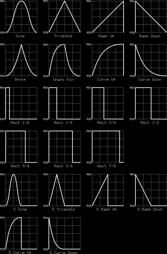
31 31
32 There are some randomly generated shapes which don t lend themselves to drawings. They are: Shape RndStep Rnd Tri Rnd +/- Rnd +0- Behavior (Short for Random Step) At the beginning of each cycle, the LFO s output jumps to a randomly chosen value and stays there for the duration of its cycle. (Short for Random Triangle) At the beginning of each cycle, the LFO chooses a new value at random and moves to that value in a linear manner over the duration of its cycle. Same as Random Step but the value is always either MIN or MAX. Same as Random Step but the value is always MIN, MAX, or halfway in between. Len (Short for Length) The Length parameter determines how long it takes for the LFO to complete one cycle; in other words, how fast it runs. The LFO Length is expressed in steps. For example, if Length is set to 3, the LFO will complete one cycle every time the sequencer plays three steps. Note that Length can be higher than the number of steps in the pattern, and has an upper limit of 256, meaning that you can set up the LFO so that the pattern repeats several times before the LFO completes one cycle. Amp AmpRnd Rng Phase 53% +/- 116 LFO 2 (Short for Amplitude) The Amplitude and Range parameters work together to set the voltage range of the LFO s output. The Range parameter (described below) chooses the minimum and maximum output voltages for the LFO, that is, the range of voltages it can generate. The Amplitude parameter sets how much of that range the LFO actually produces, and is expressed as a percentage from zero to 100%. 100% means that the LFO s output will swing between the minimum and maximum values set by the Range parameter. 50% means that the output will cover half of that range, starting at zero volts, and 0% means 0V comes out. For example, a Range setting of + and an Amplitude of 40% will make the LFO s output vary between 0V and +2V. A Range of +/- and an Amplitude of 70% will produce output voltages from -3.5V to +3.5V. 32
33 AmpRnd (Short for Amplitude Randomization) The AmpRnd setting introduces random variations in the LFO s output level, and has a range of zero to 100%. If set to zero, the LFO s output will travel predictably across the voltage range set by the Amplitude and Range parameters. As you increase AmpRnd, the maximum level of the LFO s output will start to vary randomly. The amount of variation is proportionate to the AmpRnd value. For example, if the Range setting is + and the Amplitude setting is 50%, the LFO s output will swing from 0V to 2.5V. If you set AmpRnd to 25%, the LFO s output will vary by up to 25% of the maximum value of 2.5V, which means that the LFO will reach voltages randomly varying between 1.875V and 2.5V. No, you don t need to pull out your calculator when using the LFO; just remember that the Amplitude parameter always sets the highest output voltage, and the AmpRnd parameter introduces random variations which will produce output voltages less than that highest value. The AmpRnd parameter affects all LFO wave shapes. Dialing in a small amount of randomization can make a simple pulse wave unpredictable and more interesting. Range The Range parameter chooses the minimum and maximum output voltages for the LFO, that is, the range of voltages it can generate. There are three choices, as shown in this table: Phase Range MIN MAX +/- -5V 5V + 0V 5V - -5V 0V AmpRnd Rng Phase 53% +/- 116 LFO 2 The Phase parameter determines where the LFO starts within its cycle when the pattern starts playing. Thanks to the LFO's roots in mathematical functions, the phase value is expressed in degrees, where a complete cycle consists of 360 degrees. The following diagram shows how the phase parameter controls where the LFO's cycle starts, for several different shapes: 33


34 8.3. Using LFOs Now that we ve described the LFO parameters, we ll point out some subtleties which may help you make the most of the LFOs Pattern Synchronization Each LFO s cycle is always reset to the beginning when Sequencer 1 starts playing a pattern. This means that the LFOs are always synchronized to the pattern, so that their effect on other modules is predictable and repeatable. However, once started, the LFOs can cycle independently of the pattern. For instance, if the pattern is 16 steps long and an LFO s Length setting is 64, the pattern will play four times before the LFO completes one cycle. Conversely, if the pattern s length is 64 and the LFO s is 16, the LFO will complete four cycles while the pattern plays once. This can become more interesting if the pattern length and LFO length aren t simple multiples of each other. If the pattern is 16 steps long and the LFO s length is 15, 34
ALGORHYTHM. User Manual. Version 1.0
 !! ALGORHYTHM User Manual Version 1.0 ALGORHYTHM Algorhythm is an eight-step pulse sequencer for the Eurorack modular synth format. The interface provides realtime programming of patterns and sequencer
Tetrapad Manual. Tetrapad. Multi-Dimensional Performance Touch Controller. Firmware: 1.0 Manual Revision:
 Tetrapad Multi-Dimensional Performance Touch Controller Firmware: 1.0 Manual Revision: 2017.11.15 Table of Contents Table of Contents Overview Installation Before Your Start Installing Your Module Panel
R H Y T H M G E N E R A T O R. User Guide. Version 1.3.0
 R H Y T H M G E N E R A T O R User Guide Version 1.3.0 Contents Introduction... 3 Getting Started... 4 Loading a Combinator Patch... 4 The Front Panel... 5 The Display... 5 Pattern... 6 Sync... 7 Gates...
multitrack sequencer USER GUIDE Social Entropy Electronic Music Instruments
 multitrack sequencer Social Entropy Electronic Music Instruments IMPORTANT SAFETY AND MAINTENANCE INSTRUCTIONS TABLE OF CONTENTS BACKGROUND... 1 CONCEPTS... 2 DIAGRAM CONVENTIONS... 3 THE BASICS WHAT
Oberkorn User Manual. Analogue Sequencer. Analogue Solutions
 Oberkorn User Manual Analogue Sequencer Analogue Solutions CONTENTS What is an analogue sequencer?... 4 That s all very well (and technical) but what would I use it for?... 4 ABOUT THIS MANUAL AND ABOUT
Written by Jered Flickinger Copyright 2019 Future Retro
 Written by Jered Flickinger Copyright 2019 Future Retro www.future-retro.com 2 TABLE OF CONTENTS Page 4 - Overview Page 5 Controls Page 6 Inputs and Outputs Page 7 MIDI Page 8 Jumper Settings Page 9 Standalone
Modcan Touch Sequencer Manual
 Modcan Touch Sequencer Manual Normal 12V operation Only if +5V rail is available Screen Contrast Adjustment Remove big resistor if using with PSU with 5V rail Jumper TOP VEIW +5V (optional) +12V } GND
Plog rev 1.0 MANUAL Overview
 Overview The Intellijel Plog is a voltage controllable digital logic device designed for musical applications. It is primarily intended to create controllable patterns from gate/ pulse sources like clocks
randomrhythm Bedienungsanleitung User Guide
 randomrhythm Bedienungsanleitung User Guide EN Foreword Whether random really exists or is just an illusion, shall be discussed by philosophers and mathematicians. At VERMONA, we found a possibility to
Shifty Manual. Shifty. Voice Allocator Hocketing Controller Analog Shift Register Sequential/Manual Switch. Manual Revision:
 Shifty Voice Allocator Hocketing Controller Analog Shift Register Sequential/Manual Switch Manual Revision: 2018.10.14 Table of Contents Table of Contents Compliance Installation Installing Your Module
User Guide. Version 2.0.0
 II User Guide Version 2.0.0 Contents Introduction... 3 What s New in Step Note Recorder II?... 3 Getting Started... 4 The Front Panel... 5 The Sequence... 5 The Piano Roll... 6 The Data Lane... 7 Velocity...
III Phrase Sampler. User Manual
 III Phrase Sampler User Manual Version 3.3 Software Active MIDI Sync Jun 2014 800-530-4699 817-421-2762, outside of USA mnelson@boomerangmusic.com Boomerang III Phrase Sampler Version 3.3, Active MIDI
StepSequencer64 J74 Page 1. J74 StepSequencer64. A tool for creative sequence programming in Ableton Live. User Manual
 StepSequencer64 J74 Page 1 J74 StepSequencer64 A tool for creative sequence programming in Ableton Live User Manual StepSequencer64 J74 Page 2 How to Install the J74 StepSequencer64 devices J74 StepSequencer64
// K4815 // Pattern Generator. User Manual. Hardware Version D-F Firmware Version 1.2x February 5, 2013 Kilpatrick Audio
 // K4815 // Pattern Generator Kilpatrick Audio // K4815 // Pattern Generator 2p Introduction Welcome to the wonderful world of the K4815 Pattern Generator. The K4815 is a unique and flexible way of generating
Shifty Manual v1.00. Shifty. Voice Allocator / Hocketing Controller / Analog Shift Register
 Shifty Manual v1.00 Shifty Voice Allocator / Hocketing Controller / Analog Shift Register Table of Contents Table of Contents Overview Features Installation Before Your Start Installing Your Module Front
Tiptop audio z-dsp.
 Tiptop audio z-dsp www.tiptopaudio.com Introduction Welcome to the world of digital signal processing! The Z-DSP is a modular synthesizer component that can process and generate audio using a dedicated
User Guide Version 1.1.0
 obotic ean C R E A T I V E User Guide Version 1.1.0 Contents Introduction... 3 Getting Started... 4 Loading a Combinator Patch... 5 The Front Panel... 6 On/Off... 6 The Display... 6 Reset... 7 Keys...
5U Oakley Modular Series
 Oakley Sound Systems 5U Oakley Modular Series VC-LFO Low Frequency Oscillator PCB Issue 2 User Manual V2.0.04 Tony Allgood B.Eng PGCE Oakley Sound Systems CARLISLE United Kingdom The suggested panel layout
XYNTHESIZR User Guide 1.5
 XYNTHESIZR User Guide 1.5 Overview Main Screen Sequencer Grid Bottom Panel Control Panel Synth Panel OSC1 & OSC2 Amp Envelope LFO1 & LFO2 Filter Filter Envelope Reverb Pan Delay SEQ Panel Sequencer Key
VARIGATE 4+ MANUAL V.1
 www.malekkoheavyindustry.com 814 SE 14TH AVENUE PORTLAND OR 97214 USA TABLE OF CONTENTS SPECIFICATIONS 1 INSTALLATION 2 DESCRIPTION 3 OVERVIEW 4-5 PROGRAMMING GATES PER STEP 6 PROGRAMMING CV/NOTES PER
Edit Menu. To Change a Parameter Place the cursor below the parameter field. Rotate the Data Entry Control to change the parameter value.
 The Edit Menu contains four layers of preset parameters that you can modify and then save as preset information in one of the user preset locations. There are four instrument layers in the Edit menu. See
// K4815 // Pattern Generator. User Manual. Hardware Version D/E Firmware Version 1.1x February 16, 2011 Kilpatrick Audio
 // K4815 // Pattern Generator Kilpatrick Audio // K4815 // Pattern Generator 2p Introduction Welcome to the wonderful world of the K4815 Pattern Generator. The K4815 is a unique and flexible way of generating
Intelligent Quantizer and Interval Generator
 µscale Intelligent Quantizer and Interval Generator Manual Revision: 2018.02.16 Table of Contents Table of Contents Overview Features Installation Before Your Start Installing Your Module Front Panel Controls
Quad Clock Distributor (QCD) from 4ms Company
 from 4ms Company") Quad Clock Distributor (QCD) from 4ms Company Eurorack Module User Manual v1.0 (2013-12-09) The Quad Clock Distributor (QCD) from 4ms Company is a four channel Voltage Controlled Clock Divider/Multiplier
Quad Clock Distributor (QCD) from 4ms Company Eurorack Module User Manual v1.0 (2013-12-09) The Quad Clock Distributor (QCD) from 4ms Company is a four channel Voltage Controlled Clock Divider/Multiplier
Synthesis Technology E102 Quad Temporal Shifter User Guide Version 1.0. Dec
 Synthesis Technology E102 Quad Temporal Shifter User Guide Version 1.0 Dec. 2014 www.synthtech.com/euro/e102 OVERVIEW The Synthesis Technology E102 is a digital implementation of the classic Analog Shift
Rhythm. Pattern Generator
 Rhythm Pattern Generator Description The Rhythm is a 4 channel pattern generator with BPM display. It ships with a multitude of genre-oriented rhythms that can be altered on a per channel basis. With each
oberkorn3 analogue sequencer user manual analogue sequencer user manual ANALOGUE SOLUTIONS oberkorn mkiii e&oe (c)
") oberkorn3 analogue sequencer user manual analogue sequencer user manual ANALOGUE SOLUTIONS oberkorn mkiii e&oe (c) 10-2006 1 Contents Intro - OBERKORN - Professional Analogue Sequencer...4 About Analogue
oberkorn3 analogue sequencer user manual analogue sequencer user manual ANALOGUE SOLUTIONS oberkorn mkiii e&oe (c) 10-2006 1 Contents Intro - OBERKORN - Professional Analogue Sequencer...4 About Analogue
QUAD LFO MANUAL V SE 14TH AVENUE PORTLAND OR USA
 www.malekkoheavyindustry.com 814 SE 14TH AVENUE PORTLAND OR 97214 USA TABLE OF CONTENTS SPECIFICATIONS 1 INSTALLATION 2 DESCRIPTION 3 CONTROLS 4-6 USING QUAD LFO WITH VARIGATE 8+ AND VARIGATE 4+ 7 WARRANTY
To ensure long, trouble-free operation, please read this manual carefully. Precautions
 Thank you purchasing the Korg ELECTRIBE M EM-1. In order to enjoy long and trouble-free use, please read this manual carefully and use the instrument correctly. E 1 To ensure long, trouble-free operation,
Table of Contents: ECHOPHON
 v2.6 Table of Contents: 2 ECHOPHON FCC -----------------------------------------------------3 Limited Warranty ----------------------------------------4 Installation --------------------------------------------------5
Limited WARRANTY: Make Noise implies and accepts no responsibility for harm to person or apparatus caused through operation of this product.
 v2.4 1 BRAINS Limited Warranty: ----------------------------------------------------2 Installation: --------------------------------------------------3 Jumpers and Cable Connections: --------------------------------4
For example, an indication of Range: 60, 67, 72, 75 (Hz) means that 60 Hz is the default value.
 means that 60 Hz is the default value.") Owner s Manual This manual explains how to use an MV-8000 in which System Program Version 3.0 is installed. About the Symbols and icons in this manual Text in square brackets [ ] refers to buttons on the
Owner s Manual This manual explains how to use an MV-8000 in which System Program Version 3.0 is installed. About the Symbols and icons in this manual Text in square brackets [ ] refers to buttons on the
Limited WARRANTY: Make Noise implies and accepts no responsibility for harm to person or apparatus caused through operation of this product.
 v2.5 2 BRAINS Limited Warranty ----------------------------------------------------3 Installation --------------------------------------------------4 Jumpers and Cable Connections --------------------------------5
y POWER USER MUSIC PRODUCTION and PERFORMANCE With the MOTIF ES Mastering the Sample SLICE function
 y POWER USER MUSIC PRODUCTION and PERFORMANCE With the MOTIF ES Mastering the Sample SLICE function Phil Clendeninn Senior Product Specialist Technology Products Yamaha Corporation of America Working with
Cedits bim bum bam. OOG series
 Cedits bim bum bam OOG series Manual Version 1.1 (06/2018) Products Version 1.0 www.k-devices.com - support@k-devices.com K-Devices, 2017. All rights reserved. INDEX 1. OOG SERIES 5 2. INSTALLATION 6 3.
American DJ. Show Designer. Software Revision 2.08
 American DJ Show Designer Software Revision 2.08 American DJ 4295 Charter Street Los Angeles, CA 90058 USA E-mail: support@ameriandj.com Web: www.americandj.com OVERVIEW Show Designer is a new lighting
fxbox User Manual P. 1 Fxbox User Manual
 fxbox User Manual P. 1 Fxbox User Manual OVERVIEW 3 THE MICROSD CARD 4 WORKING WITH EFFECTS 4 MOMENTARILY APPLY AN EFFECT 4 TRIGGER AN EFFECT VIA CONTROL VOLTAGE SIGNAL 4 TRIGGER AN EFFECT VIA MIDI INPUT
Description. Never run out of envelopes again.
 Contour Description Never run out of envelopes again. Contour is a quad envelope generator. Each channel has looping, CV over attack and decay, as well as unique chaining capabilities. This makes for the
CIRCADIAN RHYTHMS User Manual
 CIRCADIAN RHYTHMS User Manual Circadian Rhythms for modular music composers INDEX Introduction... p.02 Section 1 Quick Start Tutorials... p.03 1 - Vertical View Basics... p.03 2 - Other Views... p.07 3
Show Designer 3. Software Revision 1.15
 Show Designer 3 Software Revision 1.15 OVERVIEW... 1 REAR PANEL CONNECTIONS... 1 TOP PANEL... 2 MENU AND SETUP FUNCTIONS... 3 CHOOSE FIXTURES... 3 PATCH FIXTURES... 3 PATCH CONVENTIONAL DIMMERS... 4 COPY
4ms Quad Pingable LFO
 4ms Quad Pingable LFO Eurorack Module User Manual v2013-04-04 (pre-release) The Quad Pingable LFO (QPLFO) from 4ms Company is a compact, playable quad modulation source of four independent and identical
MANUAL v.3 CONTACT MORE THAN LOGIC. UNITING ART + ENGINEERING.
 MANUAL v.3 MORE THAN LOGIC. UNITING ART + ENGINEERING. CONTACT email: info@meris.us phone: 747.233.1440 website: www.meris.us TABLE OF CONTENTS SECTION 1 PG. 1 FRONT PANEL CONTROLS SECTION 2 PG. 2-4 GLOBAL
Please contact with any questions, needs & comments... otherwise go MAKE NOISE.
 soundhack ECHOPHON Limited WARRANTY: Make Noise warrants this product to be free of defects in materials or construction for a period of two years from the date of manufacture. Malfunction resulting from
Start/Stop works in each mode, and puts the pattern back to the starting point step 1 of the current pattern.
 Sequencer Modes In all six modes the playing of the sequencer is guaranteed. You can change the modes, while the sequencer is running. Switching into another mode, takes place after the last step of the
Fraction by Sinevibes audio slicing workstation
 Fraction by Sinevibes audio slicing workstation INTRODUCTION Fraction is an effect plugin for deep real-time manipulation and re-engineering of sound. It features 8 slicers which record and repeat the
rhythmic step sequencer user manual
 rhythmic step sequencer user manual Analogue Solutions Generator Manual Introduc)on... 3 Generator Layout... 4 Generator:... 5 MIDI (DAW Use) or CV & Gate?... 5 Feature Overview... 5 What will it work
Using Impact LX+ with Reason
 www.nektartech.com Using Impact LX+ with Reason Reason Integration Setup and Configuration The Impact LX+ Reason Integration is compatible with all Reason products from version 5 or higher. These instructions
COPYING A PATTERN...35
 f TABLE OF CONTENTS INTRODUCTION...5 WELCOME TO THE SR18 DRUM MACHINE!...5 GROUND RULES...5 CONNECTION DIAGRAM...8 TOP PANEL PHYSICAL LAYOUT...9 GENERAL CONTROLS...9 NAVIGATION BUTTONS...10 MODE BUTTONS...10
Four Head dtape Echo & Looper
 Four Head dtape Echo & Looper QUICK START GUIDE Magneto is a tape-voiced multi-head delay designed for maximum musicality and flexibility. Please download the complete user manual for a full description
MCV24 MIDI-CV/GATE/SYNC INTERFACE
 DOEPFER MCV24 MIDI-CV/GATE/SYNC INTERFACE Preliminary English owners manual written by EMIS (C) 1999 Revision 1.0 July 1999 Controls and connections Frontpanel 1 2 3 4 5 6 7 8 9 10 11 1 32 character backlit
Pressure Points. v. 2.5
 Pressure Points v. 2.5 2 Pressure Points FCC-------------------------------------------------------------------3 Limited Warranty ----------------------------------------------------4 Installation ----------------------------------------------------5
Cedits bim bum bam. OOG series
 Cedits bim bum bam OOG series Manual Version 1.0 (10/2017) Products Version 1.0 (10/2017) www.k-devices.com - support@k-devices.com K-Devices, 2017. All rights reserved. INDEX 1. OOG SERIES 4 2. INSTALLATION
RE-303 CPU. SONIC-POTIONS!!! PRELIMINARY DRAFT!!! v WORK IN PROGRESS
 RE-303 CPU SONIC-POTIONS!!! PRELIMINARY DRAFT!!! v 0.911 WORK IN PROGRESS Intro... 3 Quickstart... 3 The random way... 3 The manual way...3 Control scheme... 4 Pattern Write Mode... 4 Auto Exit... 4 Normal
MP212 Principles of Audio Technology II
 MP212 Principles of Audio Technology II Black Box Analysis Workstations Version 2.0, 11/20/06 revised JMC Copyright 2006 Berklee College of Music. All rights reserved. Acrobat Reader 6.0 or higher required
Original Marketing Material circa 1976
 Original Marketing Material circa 1976 3 Introduction The H910 Harmonizer was pro audio s first digital audio effects unit. The ability to manipulate time, pitch and feedback with just a few knobs and
Spectral Multiband Resonator from 4ms Company Eurorack Module User Manual v1.1 (firmware v5: December 2016)
") Spectral Multiband Resonator from 4ms Company Eurorack Module User Manual v1.1 (firmware v5: December 2016) The Spectral Multiband Resonator from 4ms Company is a versatile resonant filter with six bandpass
Spectral Multiband Resonator from 4ms Company Eurorack Module User Manual v1.1 (firmware v5: December 2016) The Spectral Multiband Resonator from 4ms Company is a versatile resonant filter with six bandpass
Noise Tools 1U Manual. Noise Tools 1U. Clock, Random Pulse, Analog Noise, Sample & Hold, and Slew. Manual Revision:
 Noise Tools 1U Clock, Random Pulse, Analog Noise, Sample & Hold, and Slew Manual Revision: 2018.05.16 Table of Contents Table of Contents Overview Installation Before Your Start Installing Your Module
Dave Jones Design Phone: (607) Lake St., Owego, NY USA
 Lake St., Owego, NY USA") Manual v1.00a June 1, 2016 for firmware vers. 2.00 Dave Jones Design Phone: (607) 687-5740 34 Lake St., Owego, NY 13827 USA www.jonesvideo.com O Tool Plus - User Manual Main mode NOTE: New modules are
Manual v1.00a June 1, 2016 for firmware vers. 2.00 Dave Jones Design Phone: (607) 687-5740 34 Lake St., Owego, NY 13827 USA www.jonesvideo.com O Tool Plus - User Manual Main mode NOTE: New modules are
Cathedral user guide & reference manual
 Cathedral user guide & reference manual Cathedral page 1 Contents Contents... 2 Introduction... 3 Inspiration... 3 Additive Synthesis... 3 Wave Shaping... 4 Physical Modelling... 4 The Cathedral VST Instrument...
S I N E V I B E S FRACTION AUDIO SLICING WORKSTATION
 S I N E V I B E S FRACTION AUDIO SLICING WORKSTATION INTRODUCTION Fraction is a plugin for deep on-the-fly remixing and mangling of sound. It features 8x independent slicers which record and repeat short
Noise Tools 1U Manual. Noise Tools 1U. Clock, Random Pulse, Analog Noise, Sample & Hold, and Slew. Manual Revision:
 Noise Tools 1U Clock, Random Pulse, Analog Noise, Sample & Hold, and Slew Manual Revision: 2018.09.13 Table of Contents Table of Contents Compliance Installation Before Your Start Installing Your Module
A clock is a free-running signal with a cycle time. A clock may be either high or low, and alternates between the two states.
 Clocks A clock is a free-running signal with a cycle time. A clock may be either high or low, and alternates between the two states. 1 The length of time the clock is high before changing states is its
Expert Sleepers Silent Way v1.7.3 User Manual
 Expert Sleepers Silent Way v1.7.3 User Manual Copyright 2009-2012 Expert Sleepers. All rights reserved. This manual, as well as the software described in it, is furnished under licence and may be used
Cedits bim bum bam. OOG series
 Cedits bim bum bam OOG series Manual Version 1.2 (12/2018) Products Version 1.0 www.k-devices.com - support@k-devices.com K-Devices, 2017. All rights reserved. INDEX 1. OOG SERIES 5 2. INSTALLATION 6 3.
SNAZZY FX TELEPHONE GAME MANUAL REV1 2015
 SNAZZY FX TELEPHONE GAME MANUAL REV1 2015 WELCOME TO THE 2015 TELEPHONE GAME MANUAL!! There is a lot of information here, in many different forms, taken from a variety of different times. While some may
YAMAHA AUTHORIZED PRODUCT MANUAL DIGITAL RHYTHM PROGRAMMER
 YAMAHA AUTHORIZED PRODUCT MANUAL DIGITAL RHYTHM PROGRAMMER YAMAHA DIGITAL RHYTHM PROGRAMMER OWNER S MANUAL Congratulations on your purchase of the Yamaha RX5 Digital Rhythm Programmer! Your RX5 has been
TEMPI FCC: Limited Warranty:
 v2.5 1 TEMPI FCC: ------------------------------------------------------------------2 Limited Warranty: -------------------------------------------------3 Installation: ----------------------------------------------------------4
The Complete Guide to Music Technology using Cubase Sample Chapter
 The Complete Guide to Music Technology using Cubase Sample Chapter This is a sample of part of a chapter from 'The Complete Guide to Music Technology', ISBN 978-0-244-05314-7, available from lulu.com.
Korg Kronos Workflow for Worship
 Korg Kronos Workflow for Worship I have been playing Korg keyboards since the OASYS in 2005. Korg has graciously carried over most of the workflow to their current product the Korg Kronos. This keyboard
ADE-32 OCTOCONTROLLER
 ADE-32 OCTOCONTROLLER Control, Modulation, Triggering and Pattern module with 12 Output Types individually assignable to 8 simultaneous Outputs. USER GUIDE 2016 Abstract Data Ltd. http://www.abstractdata.biz
Chapter 40: MIDI Tool
 MIDI Tool 40-1 40: MIDI Tool MIDI Tool What it does This tool lets you edit the actual MIDI data that Finale stores with your music key velocities (how hard each note was struck), Start and Stop Times
To ensure long, trouble-free operation, please read this manual carefully. Precautions
 Thank you purchasing the Korg ELECTRIBE A EA-. In order to enjoy long and trouble-free use, please read this manual carefully and use the instrument correctly. E To ensure long, trouble-free operation,
MC9211 Computer Organization
 MC9211 Computer Organization Unit 2 : Combinational and Sequential Circuits Lesson2 : Sequential Circuits (KSB) (MCA) (2009-12/ODD) (2009-10/1 A&B) Coverage Lesson2 Outlines the formal procedures for the
BodyBeat Metronome Instruction Manual
 BodyBeat Metronome Instruction Manual Peterson Electro-Musical Products, Inc. 2013 Power The StroboPlus contains a powerful internal rechargeable Lithium-Ion battery. Before initial use, we recommend that
(Refer Slide Time: 2:05)
") (Refer Slide Time: 2:05) Digital Circuits and Systems Prof. S. Srinivasan Department of Electrical Engineering Indian Institute of Technology, Madras Triggering Mechanisms of Flip Flops and Counters Lecture
(Refer Slide Time: 2:05) Digital Circuits and Systems Prof. S. Srinivasan Department of Electrical Engineering Indian Institute of Technology, Madras Triggering Mechanisms of Flip Flops and Counters Lecture
UNIT IV. Sequential circuit
 UNIT IV Sequential circuit Introduction In the previous session, we said that the output of a combinational circuit depends solely upon the input. The implication is that combinational circuits have no
Rebis Audio Ltd. RA226 Digital Sampler User Guide
 Rebis Audio Ltd. RA226 Digital Sampler User Guide CONTENTS Page Caution 2 Powering Up 2 Controls 3, 4 Detailed Description Input Level Set 5 Recording 5 Sampling 5 Multiple Samples 6 Editing 6 Playback
(Refer Slide Time 1:58)
") Digital Circuits and Systems Prof. S. Srinivasan Department of Electrical Engineering Indian Institute of Technology Madras Lecture - 1 Introduction to Digital Circuits This course is on digital circuits
Digital Circuits and Systems Prof. S. Srinivasan Department of Electrical Engineering Indian Institute of Technology Madras Lecture - 1 Introduction to Digital Circuits This course is on digital circuits
XILS 3. User Manual
 XILS 3 User Manual www.xils-lab.com - 1 - Table of contents 1 Introduction... 3 2 Features... 5 3 Installation... 6 3.1 Windows (XP, VISTA)... 6 3.2 Mac (OSX 10.3.9 and later)... 6 4 Quick Start... 7 4.1
Reference Manual. Using this Reference Manual...2. Edit Mode...2. Changing detailed operator settings...3
 Reference Manual EN Using this Reference Manual...2 Edit Mode...2 Changing detailed operator settings...3 Operator Settings screen (page 1)...3 Operator Settings screen (page 2)...4 KSC (Keyboard Scaling)
Spectral Multiband Resonator from 4ms Company Eurorack Module User Manual v1.0 (July 2015)
") Spectral Multiband Resonator from 4ms Company Eurorack Module User Manual v1.0 (July 2015) The Spectral Multiband Resonator from 4ms Company is a versatile resonant filter with six bandpass resonators/filters
Spectral Multiband Resonator from 4ms Company Eurorack Module User Manual v1.0 (July 2015) The Spectral Multiband Resonator from 4ms Company is a versatile resonant filter with six bandpass resonators/filters
Background. About automation subtracks
 16 Background Cubase provides very comprehensive automation features. Virtually every mixer and effect parameter can be automated. There are two main methods you can use to automate parameter settings:
The 01X Configuration Guide
 The 01X Configuration Guide A Very Brief Introduction Welcome to the world of learning! Like many of you, I have spent countless hours reading and re-reading the 01x and the Cubase SX owner's manuals,
MAutoPitch. Presets button. Left arrow button. Right arrow button. Randomize button. Save button. Panic button. Settings button
 MAutoPitch Presets button Presets button shows a window with all available presets. A preset can be loaded from the preset window by double-clicking on it, using the arrow buttons or by using a combination
bindubba1 The only real rule with nonlinearcircuits panels is BLUE jacks = INPUT RED jacks = OUTPUT
 The two sequencers are happy to operate independently of each other but for greater entertainment and general synchronised lunacy it is good to couple them. In which case usually bindubba1 is the top and
Introduction. NAND Gate Latch. Digital Logic Design 1 FLIP-FLOP. Digital Logic Design 1
 2007 Introduction BK TP.HCM FLIP-FLOP So far we have seen Combinational Logic The output(s) depends only on the current values of the input variables Here we will look at Sequential Logic circuits The
Inspire Station. Programming Guide. Software Version 3.0. Rev A
 Inspire Station Programming Guide Software Version 3.0 Rev A Copyright 2016 Electronic Theatre Controls, Inc. All rights reserved. Product information and specifications subject to change. Part Number:
Night Hawk Firing System User s Manual
 Firmware Version 2.53 Page 1 of 37 Table of Contents Features of the Night Hawk Panel... 4 A reminder on the safe use of Electronic Pyrotechnic Firing Systems... 5 Night Hawk Firing Panel Controls... 6
Catch or Die! Julia A. and Andrew C. ECE 150 Cooper Union Spring 2010
 Catch or Die! Julia A. and Andrew C. ECE 150 Cooper Union Spring 2010 Andrew C. and Julia A. DLD Final Project Spring 2010 Abstract For our final project, we created a game on a grid of 72 LED s (9 rows
(Refer Slide Time: 2:00)
") Digital Circuits and Systems Prof. Dr. S. Srinivasan Department of Electrical Engineering Indian Institute of Technology, Madras Lecture #21 Shift Registers (Refer Slide Time: 2:00) We were discussing
Digital Circuits and Systems Prof. Dr. S. Srinivasan Department of Electrical Engineering Indian Institute of Technology, Madras Lecture #21 Shift Registers (Refer Slide Time: 2:00) We were discussing
QUICK START GUIDE. GP-3 Mini-Grand Digital Piano
 QUICK START GUIDE GP-3 Mini-Grand Digital Piano QUICK START GUIDE INDEX PLAYING THE DEMO SONGS... 2 PLAYING SONGS FROM THE FLOPPY DISKS... 3 BUY OR DOWNLOAD SONGS TO PLAY... 4 USING THE LCD AND ITS CONTROLS..
SNG-2150C User s Guide
 SNG-2150C User s Guide Avcom of Virginia SNG-2150C User s Guide 7730 Whitepine Road Revision 001 Richmond, VA 23237 USA GENERAL SAFETY If one or more components of your earth station are connected to 120
Clocks. Sequential Logic. A clock is a free-running signal with a cycle time.
 Clocks A clock is a free-running signal with a cycle time. A clock may be either high or low, and alternates between the two states. The length of time the clock is high before changing states is its high
KARMA (Kay Algorithmic Realtime Music Architecture) Technology has been licensed from Stephen Kay, and is protected by U.S. Patents 5,486,647,
 Technology has been licensed from Stephen Kay, and is protected by U.S. Patents 5,486,647,") E 1 KARMA (Kay Algorithmic Realtime Music Architecture) Technology has been licensed from Stephen Kay, and is protected by U.S. Patents 5,486,647, 6,084,171, 6,087,578, 6,103,964, 6,121,532, and 6,121,533.
E 1 KARMA (Kay Algorithmic Realtime Music Architecture) Technology has been licensed from Stephen Kay, and is protected by U.S. Patents 5,486,647, 6,084,171, 6,087,578, 6,103,964, 6,121,532, and 6,121,533.
Nodal. GENERATIVE MUSIC SOFTWARE Nodal 1.9 Manual
 Nodal GENERATIVE MUSIC SOFTWARE Nodal 1.9 Manual Copyright 2013 Centre for Electronic Media Art, Monash University, 900 Dandenong Road, Caulfield East 3145, Australia. All rights reserved. Introduction
S I N E V I B E S ROBOTIZER RHYTHMIC AUDIO GRANULATOR
 S I N E V I B E S ROBOTIZER RHYTHMIC AUDIO GRANULATOR INTRODUCTION Robotizer by Sinevibes is a rhythmic audio granulator. It does its thing by continuously recording small grains of audio and repeating
Logic Gates, Timers, Flip-Flops & Counters. Subhasish Chandra Assistant Professor Department of Physics Institute of Forensic Science, Nagpur
 Logic Gates, Timers, Flip-Flops & Counters Subhasish Chandra Assistant Professor Department of Physics Institute of Forensic Science, Nagpur Logic Gates Transistor NOT Gate Let I C be the collector current.
SCENEMASTER 3F QUICK OPERATION
 SETTING PRESET MODE SCENEMASTER 3F QUICK OPERATION 1. Hold [RECORD], and press [CHNS] (above the Channels Master) to set Scenes, Dual, or Wide mode. WIDE MODE OPERATION In Wide mode, both CHANNELS and
Software version 2.0. Operator's Manual
 3 Software version 2.0 Operator's Manual By Roger Linn Copyright 1987, 1988, 1989 Akai Electric Co., LTD. Document revision date: April 20, 1989 4 READ THIS BEFORE YOU START! Power requirements Power requirements
PICO SEQ FEATURES TECHNICAL SPECS
 PICO Thank you for purchasing Erica Synths Pico Series module! With Pico Series we challenged ourselves can we make ANY superior functionality synth module 3HP wide and affordable? Erica Pico is mighty,