MIDI2DMX PRO. solid state MIDI to DMX converter. wwww.midi2dmx.eu
|
|
|
- Audrey Freeman
- 5 years ago
- Views:
Transcription

1 MIDI2DM PRO solid state MIDI to DM converter wwww.midi2dmx.eu May 2011
2 From the authors Artistic and stage activity is like others aspects of our life - competition on the market is everywhere. On the free market the winner is who delivers the same service and/or product with lower price. But better product for the same price needs better tools. Currently we would like to present small and smart device, which may be very useful in any activity where spectators would like to listen good music and watch attractive stage lightning. MIDI2DM converter is designed for easy control over lights and all others DM devices (fog/smoke generators, lasers, heads etc.) on the stage. Full control over DM devices is realized using MIDI - very good known protocol in the music area. User do not needs anymore expensive DM devices - consoles, mixers and qualified personnel as well. Total control with full synchronization between music and lights - everything is possible now. Three simple questions: 1) Are you working in the MIDI environment? 2) Do you would like to have full control over DM devices in the MIDI environment? 3) Do you think, that money for DM devices may have better target? If Your answers are 3 times YES, it means that this is time to buy MIDI2DM converter. Fully professional MIDI messages to DM control converter. MIDI2DM is the first around the world - so functional, so small and so inexpensive device, offering full, synchronised control over lights in the sound control environment. MD&CW Team
3 Introduction MIDI2DM is professional, based on the 16 MIPS microcontroller converter, which translates MIDI messages to DM control signals in real time. You may use it wherever you need control DM stage devices from the MIDI environment. MIDI2DM enables access and control of all 512 channels of the DM protocol with the natural synchronization with the music. Additionally you may use standard MIDI sequencers and mixers to generate all stage events with any kind of DM controlled equipment (lasers, fog/smog generators, heads, PAR s etc.) The control over DM devices is realized by standard MIDI channels messages Note On and Control Change. Each NO and CC message holds the information about used MIDI channel, note frequency (NO) or controller number (CC) and value of the control (velocity for NO). Note number (frequency) in NO mode or controller number in CC mode are available as the numbers in the range and may be used to choose DM channel in the range. Because of 512 DM channels we need additional information to have access to channels above 128. This is made by classic data banking techniques. To select the needed bank of the 128 DM channels, this device uses MIDI channel number. Details of the bank selecting techniques are explained in mode descriptions further in this manual. Value of the MIDI message (i. e. Velocity for NO) is used as a value for chosen DM channel. DM control standard uses 256 values for each channel, the range is MIDI message format accepts 128 values only, in the range Because of this difference, value from the MIDI message is multiplied by 2, and therefore final range available for DM channel is (255 levels). Due to consistency of the control while using Note On and Control Change messages and due to control rules of the DM equipment, this device by default uses Note On (or Control Change) with velocity equal to 0 (zero) to switch off light in the corresponding channel. Each value (Velocity) in the DM channel (0 or higher) will stay fixed until next message for this DM channel will be received. Change of this feature is possible using Additional settings control set. MIDI Note Off message is used in [DM4 - L&S/ILF] mode. The abbreviation L&S is from Light and Sound, ILF is polish abbreviation for this mode. Details are explained below. MIDI2DM converter has special User Mode as well [Mode 8]. Using this mode user can prepare various variants of the DM control signals - fixed, dynamic, active on notes range etc. Using special software, called MIDI2DM Control Center, setting the controls is easy. Details below.

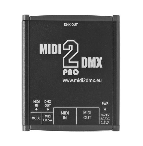
4 General view
![Controls 1 2 3 4 5 6 7 8 1. [MIDI IN] - incoming MIDI messages, yellow 2. [DM OUT] - outgoing DM data, green 3. [PWR] - power, red 4. [MODE] - work mode switch (0-F) 5. [MIDI Ch. Sw.](/docs-images/86/93321714/images/5-0.jpg "] - MIDI Channel Switch and DM level in the service mode 6. [MIDI IN] - MIDI input 7. [MIDI OUT] - MIDI output, same as input but electrically refreshed 8. [9-24V AC/DC 1.")
5 Controls [MIDI IN] - incoming MIDI messages, yellow 2. [DM OUT] - outgoing DM data, green 3. [PWR] - power, red 4. [MODE] - work mode switch (0-F) 5. [MIDI Ch. Sw.] - MIDI Channel Switch and DM level in the service mode 6. [MIDI IN] - MIDI input 7. [MIDI OUT] - MIDI output, same as input but electrically refreshed 8. [9-24V AC/DC 1.5W] - power plug, AC or DC, 9-24V range, polarity not important Work modes [MODE] 0 - Mode DM128 Note On [DM128 NO] Controls DM channels using notes (Note On message). After receiving Note On message (code 09H), velocity value is multiplied by 2 and applied for the channel determined by note number. In this mode MIDI2DM device uses MIDI messages from one MIDI channel only. Active MIDI channel should be set on [MIDI Ch. Sw.], where MIDI channels in range 1 16 are represented by positions 0 F. 1 - Mode DM256 Note On [DM256 NO] Controls DM channels using notes (Note On message). After receiving Note On message (code 09H), velocity value is multiplied by 2 and applied for the channel determined by note number and MIDI Channel. DM Channel range is determined by MIDI Channel: - Note On messages in the 16. MIDI channel controls DM channels in range Note On messages in the 15. MIDI channel controls DM channels in range Mode DM384 Note On [DM384 NO] Controls DM channels using notes (Note On message). After receiving Note On message (code 09H), velocity value is multiplied by 2 and applied for the channel determined by note number and MIDI Channel. DM Channel range is determined by MIDI Channel: - Note On messages in the 16. MIDI channel controls DM channels in range Note On messages in the 15. MIDI channel controls DM channels in range Note On messages in the 14. MIDI channel controls DM channels in range Mode DM512 Note On [DM512 NO] Controls DM channels using notes (Note On message). After receiving Note On message (code 09H), velocity value is multiplied by 2 and applied for the channel determined by note number and MIDI Channel. DM Channel range is determined by MIDI Channel: - Note On messages in the 16. MIDI channel controls DM channels in range Note On messages in the 15. MIDI channel controls DM channels in range Note On messages in the 14. MIDI channel controls DM channels in range
6 - Note On messages in the 13. MIDI channel controls DM channels in range Mode DM128 Control_Change [DM128 CC] Controls DM channels using Control Change message. After receiving Control Change message (code 0BH), velocity value is multiplied by 2 and applied for the channel determined by controller number. In this mode MIDI2DM device uses MIDI messages from one MIDI channel only. Active MIDI channel should be set on [MIDI Ch. Sw.], where MIDI channels in range 1 16 are represented by positions 0 F. 5 - Mode DM256 Note On/Control_Change [DM256 NO/CC] Controls DM channels using Control Change message. After receiving Note On message (code 09H) in MIDI Channel 16, velocity value is multiplied by 2 and applied for the DM channel determined by note number. After receiving Control Change message (code 0BH) in MIDI Channel 15, controller value is multiplied by 2 and applied for the DM channel determined by controller number and MIDI Channel. DM Channel range is determined by MIDI Channel: - Note On messages in the 16. MIDI channel controls DM channels in range Control Change messages in the 15. MIDI channel controls DM channels in range Mode DM384 Note On/Control_Change [DM384 NO/CC] Controls DM channels using Control Change message. After receiving Note On message (code 09H) in MIDI Channel 16, velocity value is multiplied by 2 and applied for the DM channel determined by note number. After receiving Control Change message (code 0BH) in MIDI Channel 14 or 15, controller value is multiplied by 2 and applied for the DM channel determined by controller number and MIDI Channel. DM Channel range is determined by MIDI Channel: - Note On messages in the 16. MIDI channel controls DM channels in range Control Change messages in the 15. MIDI channel controls DM channels in range Control Change messages in the 14. MIDI channel controls DM channels in range Mode DM512 Note On/Control_Change [DM512 NO/CC] Controls DM channels using Control Change message. After receiving Note On message (code 09H) in MIDI Channel 16, velocity value is multiplied by 2 and applied for the DM channel determined by note number. After receiving Control Change message (code 0BH) in MIDI Channel 13, 14 or 15, controller value is multiplied by 2 and applied for the DM channel determined by controller number and MIDI Channel. DM Channel range is determined by MIDI Channel: - Note On messages in the 16. MIDI channel controls DM channels in range Control Change messages in the 15. MIDI channel controls DM channels in range Control Change messages in the 14. MIDI channel controls DM channels in range Control Change messages in the 13. MIDI channel controls DM channels in range DM User Mode [DM512 UM] All DM channels (1 512) are individually controlled accordingly to rules set by user. For details see User Mode chapter. 9 - Manual control all DM channels [DM512 - Ctrl] All DM channels (1 512) are set to value determined by MIDI channel switch in step 16-0=0, 1=16, 2=32,... F=256 (maintenance/service mode). A - DM channels on 25% [DM512-25%] All DM channels (1 512) are set to value 64-25% (maintenance/service mode). B - DM channels on 50% [DM512-50%] All DM channels (1 512) are set to value % (maintenance/service mode).
7 C - DM channels on 75% [DM512-75%] All DM channels (1 512) are set to value % (maintenance/service mode). D - DM channels on 100% [DM %] All DM channels (1 512) are set to value % (maintenance/service mode). E MIDI controls all DM channels simultaneously [DM512 Note=0] Device receives messages Note ON for note #0 in MIDI channel #16 only. All DM channels (1 512) are set to Velocity value multiplied by 2. F - Light & Sound mode for 4 channels PAR LED [DM4 - L&S/ILF] Devices analyses incoming MIDI Note On/Note Off messages on all MIDI channels and outputs control signals for color lights in 4 DM channels. Details: PAR lamp constantly switched on - DM value in channel #1 set to 128 (50%). Dynamic control is achieved by incoming MIDI messages. Note On (09H) sets DM value according to current velocity. Note Off (08H) sets DM value equal to 0. According to the note number (frequency) device sets appropriate DM channel: - DM #2 channel, usually Red, notes range DM #3 channel, usually Green, notes range DM #4 channel, usually Blue, notes range

8 Control Software - MIDI2DM Control Center MIDI2DM PRO has own PC (Windows) software which controls internal functions. This software is the same for both versions of MIDI2DM devices - BASIC and PRO. Screens below shows main form of the application before software has identified the device version. There are 4 tabs with settings for each type of the device. Currently unused functions will be hidden after proper device identification. First screen shows User Mode channels settings tab, described later in User Mode section. Preparing device to work with MIDI2DM Control Center expect two MIDI connections between device and MIDI interface in closed loop fashion. It means that MIDI IN from device should be connected to MIDI OUT of the computer s MIDI interface and device s MIDI OUT should be connected to MIDI IN connector of the computer s interface.
. This setting is active for predefined modes (0-7) and for User Mode [8 - DM512 UM].")
9 Additional Settings tab shows functions available for each type of the devices (BASIC & PRO). Use Note Off - DM channel value is set using Note On Velocity or Control Change value. The user may also activate Note Off function which works like Note On with velocity equals 0 (zero). This setting is active for predefined modes (0-7) and for User Mode [8 - DM512 UM]. Set Zero Value Offset - some MIDI controllers don t send zero value as a Velocity or Control Change channel number. In this case this is impossible to switch off particular channel in User Mode. Setting Zero Value Offset to 3 means that all incoming value data will be decreased by 3 and than multiplied by 2 as a DM channel value. It means that Velocities or CC channel numbers 1,2,3 will become value 0 to switch off current DM channel. Maximum value 127 is reduced by 3 as well. Available range is from 0 to 10.

10 Basic modes configuration tab is for use with MIDI2DM Basic device only.
11 Firmware Upload tab controls functions like device identification, firmware upload etc. Screen below shows Firmware Upload tab after identification of the device and software versions. Message Going to work... appears when Firmware upload mode was set to Read BL & FW Version. Then, after power up, data is fetched from the device and the device enters the normal working mode. In general most operations on this tab are active during power-up of the device, however in the User Mode [Mode 8] user can restart device using Restart device button. Before firmware upgrade user should point firmware file (extension *.BI) for upgrade. While upgrading firmware errors may occurs. In the section Firmware upload problems user will find some important notices and solutions.

12 Firmware upload Screens below shows messages during firmware upload. Each block s number is displayed during upload process, preceded by message Upload INIT..., which appears after power up. If something goes wrong, user sees a screen like the one below. If this message appears always after block #001, user may be almost sure that used USB-MIDI interface has limitation of the SYSE command length. In other cases the USB bus or the computer may be currently too busy.
13 Firmware upload problems Firmware upload process is prepared as safe as possible and cannot destroy the device. However the device should not be disconnected from power during the upgrading process. If upgrade process finishes without success, device can t work in normal modes because of only partially loaded software. The bootloader works without any problem anytime, so user should repeat upgrade process using settings Firmware upload mode. Although if the partially loaded firmware shows newer version from broken upgrade process, Upload FW if same or older should be chosen before next upgrade attempt. USB-MIDI Interfaces problems Firmware upload requires that the USB bus is not busy during the process. Some multi-port USB-MIDI devices can t serve messages as fast as needed for firmware upload. Additionally there are a lot of cheap USB-MIDI interfaces where there is a limitation of SYSE messages length. In this case firmware upload isn t possible as well and user should change interface. Before the firmware upload a test of the interface is recommended. Simple interface test will be performed when user chooses Interface test and powers up the device.

 over the table, user may copy and paste data between channels, add and/or edit description of the channel etc.")
14 User Mode All DM channels (1 512) are individually controlled accordingly to rules prepared by user. Prepared data may be read from device, written back to device and stored in disk file for future use. Using commands from standard menu user can clear all data in device, prepare empty data for all DM channels for future edit, save edited data to disk, read data from and write data to device. Using context menu (right mouse button) over the table, user may copy and paste data between channels, add and/or edit description of the channel etc. Writing data to device clears all previously stored DM channels. Table shows sample sets of the control data included in DMUser_sample_1.csv file, available with software. There are 5 modes of control and accordingly to the selected mode, DM channel lines will be highlighted with user defined color. Screen below shows DMUser settings dialog (Menu: Settings -> Colors) where control modes are shown. When mouse pointer hovers over the dialog items, the hints are displayed.
15 Control modes Note On Active Selected DM channel will be activated with value of Velocity multiplied by 2, when device receives Note On message in selected MIDI channel and defined notes range. This kind of control on the sample screen is set for DM channel #4, MIDI channel is 16 and note range is from C-1 to E-1. Note On Value Selected DM channel will be activated with value defined in the last column Data = of the table. Current Velocity value of the incoming message will be ignored. This kind of control is visible for DM channels #2, #3, #8, #10, #11 and #12 with various sets of value and notes range. Control Change Active Selected DM channel will be activated with controller value multiplied by 2 of controller number, when device receives Control Change message in selected MIDI channel and defined controller number range. This kind of control on the sample screen is set for DM channel #7, MIDI channel is 16 and controller number range is only one - from 1 to 1. Controller number is shown after slash with note symbol C#-1/1. Control Change Value Selected DM channel will be activated with value defined in the last column Data = of the table. Current controller value of the incoming message will be ignored. This kind of control is visible for DM channel #6. DM Always Value Selected DM channel will be active always with value selected. On the sample screen DM channels #1, #5 and #9 are set to this mode. Channel #1 will always be active with value 51 (ca 20%), channel #5 with value 127 (50%), and channel #9 with value 255 (100%). Control table columns description DM ch. - number of DM channel Act. ctrl/value - selection of control type between dynamic (Active control) and fixed (Value). Active control uses incoming data as a control signal for selected channel, when Value is selected, this DM channel will be controlled using only value set in next column - Data =. MIDI ch. - selects MIDI channel used for control of this DM channel. Active On - selects MIDI message which activates this DM Channel, available values are Note On and Control Change. From Note On/CC - selects start of the range in which current DM channel will be active. Maximum range is from current to the end of available values (127) notes or controller numbers. To Note On/CC - selects end of the range in which current DM channel will be active. Selected note/controler number is the last one active in the range. Data type Velocity/Value - selects final control value for current DM channel. If Velocity is in use, value for DM channel will be set as received Velocity value multiplied by 2 (NO) or contoler value multiplied by 2 if CC message is selected for this DM channel. If Value is in use, control value for DM channel will be fixed as set in last column Data =. Description - for easy use of the settings user may add a text description for each DM channel which may remember which device and/or their function is assigned to current DM channel. This data can t be stored into device and stays in disk file only, so user have to remember to save disk file before clearing the settings table. Right mouse button opens a context menu over the table. A large form can be opened from there if longer description is necessary.
 and may be useful when user wants to see the full description, instead of using small Description field above the")
16 DM Channel description Screen below shows DM Channel description form. This window opens from the context menu over channels settings table (right click) and may be useful when user wants to see the full description, instead of using small Description field above the table. Some characters (like, or ; ) aren t available because of simple CSV format used for storing data. Important notes to User Mode There is a difference between preprogrammed modes (0-7) and the User Mode while servicing Note Off message. In this mode Note Off signal is used to reset DM channel data to 0 (i. e. switch off lights). Remember that by default in modes 0-7 to switch off a DM channel, message Note On with Velocity = 0 must be used. Change this feature in Additional Settings tab. This kind of control is very useful for MIDI drums and helps a lot in controlling lights and heads as well. While using Control Change messages in User Mode, controller number equal 0 must be used to reset DM channel value. If the controller used does not allow the Controller Number to equal zero, the required offset may be set using Additional Settings tab.
17 Work modes - MIDI/DM channels service summary Work mode Active MIDI Channels Available DM channels Mode 0 [DM128 NO] Mode 1 [DM256 NO] Mode 2 [DM384 NO] Mode 3 [DM512 NO] Mode 4 [DM128 CC] One from 16. MIDI channels determined by software One from 16. MIDI channels determined by software Mode 5 [DM256 NO/CC] Mode 6 [DM384 NO/CC] Mode 7 [DM512 NO/CC] Mode 8 [User Mode] 16 [Note ON] 15 [Control Change] 16 [Note On] 15 [Control Change] 14 [Control Change] 16 [Note On] 15 [Control Change] 14 [Control Change] 13 [Control Change] 1-16 [Note On] 1-16 [Control Change]
18 Technical data: Power: Power consumption: Dimensions: Weight: Enclosure: 9-24 AC/DC, 2.1/5.5 mm plug, polarity not important ca. 1,5 VA 100x85x30 mm ca. 200 g aluminum casing with plastic caps MIDI Input: DIN-5 socket, optical isolated MIDI Output: DIN-5 socket, optical isolated, signal electrically regenerated DM Output: LR 3 (F) socket MIDI IN->OUT latency: Time of one MIDI frame - 0,29 ms LED signals: MIDI In LED yellow, blink - MIDI message has been received, any channel DM Out LED green, blink - DM target channel was set green, constant - DM manual control mode #9 PWR LED red, 1 sec. blink - power good, microcontroller in normal condition red, constant, low intensity - probably power voltage too low, check power source red, constant, high intensity or off after blinking - software problem, microcontroller hangs up, reset required (power off, then power on again) Power On LED signals sequence: Phase 1. PWR LED red, constant, low intensity ca 0,2 sec. Phase 2. DM Out LED green, constant PWR LED red, constant, high intensity MIDI In LED yellow, blinks 3 times - device is waiting for firmware upgrade. Phase 3. DM Out LED, PWR LED, MIDI In LED blinks 2 times - device is going to normal mode Manufacturer MD&CW Team mid2dmx@midi2dmx.eu Poland
19 MIDI Implementation Card Function Basic Default Chanel Changed Mode Default Messages Altered Note True Voice Number DM channels access Active MIDI channels Notes DM channels selecting and controlling. Number of active MIDI channels depends of the mode. DM channel number Velocity Note ON After Touch Note OFF Key s Channel ; DM channel value Pitch Bend Control Change Program Change DM channels selecting and controlling. Number of active MIDI channels depends of the mode. System Exclusive 0 Firmware upgrade System Song Position Pointer Common Song Sel Tune Request System Clock Real Time Commands Aux All Sounds Off Messages Reset All Controllers Local ON/OFF All Notes OFF Active Sensing System Reset Notes: 0 - Yes - No
SAT IF distribution system
 7. Technical specifications Type cs43 RF input frequency range pr. 50-350 MHz inputs number 4 level pr. 55...88 dbµv 60...93 dbµv symbol rate 3 45 Ms/s return loss/impedance > 0 db/75 Ω LNB powering/control
SwiftMix Automation Safety
 Operations Manual SwiftMix TM Automation Thank you for your purchase of the SwiftMix automation for the 5088 console. Everyone at Rupert Neve Designs hopes you enjoy using this tool as much as we have
Rack-Mount Receiver Analyzer 101
 Rack-Mount Receiver Analyzer 101 A Decade s Worth of Innovation No part of this document may be circulated, quoted, or reproduced for distribution without prior written approval from Quasonix, Inc. Copyright
Single cable multiswich programmer PC102W
 Single cable multiswich programmer PC102W 1. Product description The PC102W - single cable multiswich programmer (in the text - programmer) is useful instrument while configuring and troubleshooting SAT
Industriefunkuhren. Technical Manual. IRIG-B Generator-Module for analogue / digital Signals of Type: IRIG-B / IEEE C / AFNOR NF S87-500
 Industriefunkuhren Technical Manual IRIG-B Generator-Module for analogue / digital Signals of Type: IRIG-B / IEEE C37.118 / AFNOR NF S87-500 Module 7628 ENGLISH Version: 02.01-06.03.2013 2 / 20 7628 IRIG-B
Video Micro Converter
 Setup Manual www.ecue.com e:cue lighting control An OSRAM Company Rev. 20101125 Contents Device Overview....................................... 4 About the Video Micro Converter...............................
VIDEO GRABBER. DisplayPort. User Manual
 VIDEO GRABBER DisplayPort User Manual Version Date Description Author 1.0 2016.03.02 New document MM 1.1 2016.11.02 Revised to match 1.5 device firmware version MM 1.2 2019.11.28 Drawings changes MM 2
Chapter 23 Dimmer monitoring
 Chapter 23 Dimmer monitoring ETC consoles may be connected to ETC Sensor dimming systems via the ETCLink communication protocol. In this configuration, the console operates a dimmer monitoring system that
Unicable II Programmer. IDLU-PROG01-OOOOO-OPP Item: Installation & User Guide
 Unicable II Programmer IDLU-PROG01-OOOOO-OPP Item: 5273 Installation & User Guide 1 2 Thank you for purchasing Inverto s advanced Unicable II programmer. Before installing and using the programmer, please
Transmitter Interface Program
 Transmitter Interface Program Operational Manual Version 3.0.4 1 Overview The transmitter interface software allows you to adjust configuration settings of your Max solid state transmitters. The following
CoLinkEx JTAG/SWD adapter USER MANUAL
 CoLinkEx JTAG/SWD adapter USER MANUAL rev. A Website: www.bravekit.com Contents Introduction... 3 1. Features of CoLinkEX adapter:... 3 2. Elements of CoLinkEx programmer... 3 2.1. LEDs description....
Polyend Poly Polyphonic MIDI to CV Converter User Manual
 Polyend Poly Polyphonic MIDI to CV Converter User Manual Made in Poland polyend.com Polyend Poly Polyphonic MIDI to CV Converter in the Eurorack format Poly is probably the easiest entry point for exploring
Troubleshooting CS800/LC900 Bikes
 Troubleshooting CS800/LC900 Bikes CS800/900LC Bike Troubleshooting Entering the Maintenance Mode 15 Touch Screen: The Maintenance Mode is designed to help the tech determine certain faults in the upper
HD/SD-SDI TO VGA CONVERTER. DAC-60 Quick Start Guide.
 HD/SD-SDI TO VGA CONVERTER DAC-60 Quick Start Guide www.datavideo.com Warranty Standard Warranty Datavideo equipment is guaranteed against any manufacturing defects for one year from the date of purchase.
application software
 application software application software Input products / Shutter Output / RF output Electrical / Mechanical characteristics: see product user manual Product reference Product designation TP device RF
Reference Guide 2015 ZOOM CORPORATION. Copying or reprinting this manual in part or in whole without permission is prohibited.
 Reference Guide 2015 ZOOM CORPORATION Copying or reprinting this manual in part or in whole without permission is prohibited. Introduction is a mixer application designed specifically for the. Using a
PQ-Box 100 Quick Start Instructions
 PQ-Box 100 Quick Start Instructions These instructions are provided for the purpose on providing a quick start to PQ-Box 100 installation and operation. Please refer to the user handbook for full details.
FOTS100 User Manual. BIOPAC Systems, Inc. Opsens Inc. 42 Aero Camino, Goleta, CA Tel (805) , Fax (805)
 , Fax (805)") FOTS100 User Manual BIOPAC Systems, Inc. 42 Aero Camino, Goleta, CA 93117 Tel (805) 685-0066, Fax (805) 685-0067 WWW.BIOPAC.COM 1 WARRANTY All products manufactured by Opsens inc. are warranted to be free
FOTS100 User Manual BIOPAC Systems, Inc. 42 Aero Camino, Goleta, CA 93117 Tel (805) 685-0066, Fax (805) 685-0067 WWW.BIOPAC.COM 1 WARRANTY All products manufactured by Opsens inc. are warranted to be free
HD/SD-SDI TO VGA CONVERTER. DAC-60 Quick Start Guide.
 HD/SD-SDI TO VGA CONVERTER DAC-60 Quick Start Guide www.datavideo.com Warranty Standard Warranty Datavideo equipment is guaranteed against any manufacturing defects for one year from the date of purchase.
Getting started with
 Getting started with Electricity consumption monitoring single phase for homes and some smaller light commercial premises OVERVIEW: The OWL Intuition-e electricity monitoring system comprises of three
application software
 application software application software Input products / Shutter Output / RF output Electrical / Mechanical characteristics: see product user manual Product reference Product designation TP device RF
Nuendo 3 / DM1000 V2 Setup and Operation
 Nuendo 3 / DM1000 V2 Setup and Operation Page 1 Nuendo 3 / DM1000 V2 Setup and Operation This document describes setup and operation for remote control of Nuendo from the DM1000 digital mixing console.
American DJ. Show Designer. Software Revision 2.08
 American DJ Show Designer Software Revision 2.08 American DJ 4295 Charter Street Los Angeles, CA 90058 USA E-mail: support@ameriandj.com Web: www.americandj.com OVERVIEW Show Designer is a new lighting
LED DRIVERS. LQC4D-V1 4 channels. User Manual FEATURES
 pag. 1/13 FEATURES Outputs: 4 x channels BUS+SEQUENCER+FADER+DIMMER+DRIVER Input: DC 12/24/48 Vdc BUS Command: DALI LOCAL Command: 4x N.O. push button (with or without memory), 0-10V, 1-10V Controls: dimmer,
MS-MATRIX - User manual
 MS-MATRIX - User manual This symbol is intended to alert the user of important operating and maintenance (servicing) instructions in the literature provided with the equipment. This symbol is intended
C8188 C8000 1/10. digital audio modular processing system. 4 Channel AES/EBU I/O. features. block diagram. 4 balanced AES inputs
 features 4 balanced AES inputs Input Sample Rate Converters (SRC) 4 balanced AES outputs Relay bypass for pairs of I/Os Relay wait time after power up Master mode (clock master for the frame) 25pin Sub-D,
Installation / Set-up of Autoread Camera System to DS1000/DS1200 Inserters
 Installation / Set-up of Autoread Camera System to DS1000/DS1200 Inserters Written By: Colin Langridge Issue: Draft Date: 03 rd July 2008 1 Date: 29 th July 2008 2 Date: 20 th August 2008 3 Date: 02 nd
Yellow Frog. Manual Version 1.1
 Yellow Frog Manual Version 1.1 1 YellowFrog Contents PC Requirements...... 2 YellowFrog Power Meter Measurement.... 3 YellowFrog PC Software..... 3 Main Screen....... 4 Input Overload....... 5 Battery
PRO-SDIVGA. SDI Extender with PC/HD Scaler & Audio OPERATION MANUAL
 PRO-SDIVGA SDI Extender with PC/HD Scaler & Audio OPERATION MANUAL Safety Precautions Please read all instructions before attempting to unpack or install or operate this equipment, and before connecting
Manual Addendum For Rerun V1.1 software 12/12/2006, RERUN-A = Serial #06A068, RERUN-P = Serial #06A031
 Manual Addendum For Rerun V1.1 software 12/12/2006, RERUN-A = Serial #06A068, RERUN-P = Serial #06A031 The Rerun product manual was written for V1.0 software. The new release, V1.1, adds a number of new
Industriefunkuhren. Technical Manual. OEM Sync-Module FE1000 (IRIG-B) ENGLISH
 ENGLISH") Industriefunkuhren Technical Manual OEM Sync-Module FE1000 (IRIG-B) ENGLISH Version: 07.02-24.03.2014 2 / 19 FE1000 IRIG-B Synchronisation - V07.02 IMPORTANT NOTES Version Number (Firmware / Manual) THE
Industriefunkuhren Technical Manual OEM Sync-Module FE1000 (IRIG-B) ENGLISH Version: 07.02-24.03.2014 2 / 19 FE1000 IRIG-B Synchronisation - V07.02 IMPORTANT NOTES Version Number (Firmware / Manual) THE
randomrhythm Bedienungsanleitung User Guide
 randomrhythm Bedienungsanleitung User Guide EN Foreword Whether random really exists or is just an illusion, shall be discussed by philosophers and mathematicians. At VERMONA, we found a possibility to
Table of Contents FCC COMPLIANCE STATEMENT... 4 WARNINGS AND PRECAUTIONS... 4 WARRANTY... 5 STANDARD WARRANTY... 5 TWO YEAR WARRANTY... 5 DISPOSAL...
 1 Table of Contents FCC COMPLIANCE STATEMENT... 4 WARNINGS AND PRECAUTIONS... 4 WARRANTY... 5 STANDARD WARRANTY... 5 TWO YEAR WARRANTY... 5 DISPOSAL... 6 1. INTRODUCTION... 7 FEATURES... 7 2. CONNECTIONS
Extra long-range RFID (proximity) card reader
 card reader") GP90A Extra long-range RFID (proximity) card reader (1) Features: Extra long reading range of up to 90 cm with ISO-size passive RFID cards*, over 100 cm with special optimized passive cards High-precision
GP90A Extra long-range RFID (proximity) card reader (1) Features: Extra long reading range of up to 90 cm with ISO-size passive RFID cards*, over 100 cm with special optimized passive cards High-precision
C8491 C8000 1/17. digital audio modular processing system. 3G/HD/SD-SDI DSP 4/8/16 audio channels. features. block diagram
 features 4 / 8 / 16 channel LevelMagic2 SDI-DSP with level or loudness (ITU-BS.1770-1/ ITU-BS.1770-2, EBU R128) control 16 channel 3G/HD/SD-SDI de-embedder 16 in 16 de-embedder matrix 16 channel 3G/HD/SD-SDI
NoteMix Player Note Mixer/Shifter/Splitter/Filter with Snapshot Morphing Rack Extension for Propellerhead Reason
 NoteMix Player Note Mixer/Shifter/Splitter/Filter with Snapshot Morphing Rack Extension for Propellerhead Reason USER MANUAL version 1.0.0 NoteMix User Manual www.retouchcontrol.com Page 1 of 26 Table
Getting started with
 PART NO. CMA11 3 MADE IN CHINA 1. Measuring CAT II 2. Max. voltage 250V ~ 3. Max. current 71 Amp Getting started with Electricity consumption & Solar PV generation monitoring single phase, for homes fitted
D/ESAM-230 AUDIO MIXER WITH THE D/ESAM-4 PROTOCOL
 TECH NOTE Super Edit Version 8.1D and later D/ESAM-230 AUDIO MIXER WITH THE D/ESAM-4 PROTOCOL This document covers Super Edit features and parameters pertaining to the D/ESAM 4 protocol developed by Graham-Patten
Standard RS232 RS ma
 1 / 5 CONTROL AND VISUALIZATION OF AC CURRENT IN SINGLE PHASE LINES BY EXTERNAL SHUNT Function Operating mode Current control Frequency control DC component control Shunt Timer Resolution Current precision
CCE900-IP-TR. User s Guide
 CCE900-IP-TR CCE900-IP-T & CCE900-IP-R User s Guide i-tech Company LLC TOLL FREE: (888) 483-2418 EMAIL: info@itechlcd.com WEB: www.itechlcd.com 1. Introduction The CCE900-IP-T & CCE900-IP-R is a solution
Functional overview. System configuration FAQ
 Vdc 206-13-40 100/110/115/12 110/125V D C MDE IN JPN RSM100 (Relay Setting and Monitoring System) The PC interface software RSM100 allows users to access Toshiba GR-series relays from a local or remote
HD ENCODULATOR TM, SD ENCODULATOR TM LUMANTEK
 Revision Number: 1.0.0 Distribution Date: June 2017 Copyrights Notice Copyright : 2006-2017 LUMANTEK Co., Ltd. All Rights Reserved. This document contains information that is proprietary to LUMANTEK. CO.,
rekordbox TM LIGHTING mode Operation Guide
 rekordbox TM LIGHTING mode Operation Guide Contents 1 Before Start... 3 1.1 Before getting started... 3 1.2 System requirements... 3 1.3 Overview of LIGHTING mode... 4 2 Terms... 6 3 Steps to easily control
4 x 4 VGA Matrix Switch
 Hall Research Technologies, Inc. 4 x 4 VGA Matrix Switch Model VSM-404 User s Manual With Serial Keypad CUSTOMER SUPPORT INFORMATION Order toll-free in the U.S. 800-959-6439 FREE technical support, Call
// K4815 // Pattern Generator. User Manual. Hardware Version D-F Firmware Version 1.2x February 5, 2013 Kilpatrick Audio
 // K4815 // Pattern Generator Kilpatrick Audio // K4815 // Pattern Generator 2p Introduction Welcome to the wonderful world of the K4815 Pattern Generator. The K4815 is a unique and flexible way of generating
SXGA096 DESIGN REFERENCE BOARD
 SXGA096 DESIGN REFERENCE BOARD For Use with all emagin SXGA096 OLED Microdisplays USER S MANUAL VERSION 1.0 TABLE OF CONTENTS D01-501152-01 SXGA096 Design Reference Board User s Manual i 1. INTRODUCTION...
Siteco Service Box User Manual 1/31
 Siteco Service Box User Manual 1/31 Contents Page I. References.......5 II. General Safety Recommendations..... 6 III. IV. Technical Details........ 7 Device Description...... 8 V. Definitions........9
TABLE OF CONTENTS. 2 SGM Light Technology 23/08/1999 Ver. 2.00
 Version 2.0 TABLE OF CONTENTS 2 SGM Light Technology 23/08/1999 Ver. 2.00 STUDIO SC USER GUIDE To Clear All the Memory...5 Manual Preset Section...6 The single or double preset:...7 To set the Single or
For example, an indication of Range: 60, 67, 72, 75 (Hz) means that 60 Hz is the default value.
 means that 60 Hz is the default value.") Owner s Manual This manual explains how to use an MV-8000 in which System Program Version 3.0 is installed. About the Symbols and icons in this manual Text in square brackets [ ] refers to buttons on the
Owner s Manual This manual explains how to use an MV-8000 in which System Program Version 3.0 is installed. About the Symbols and icons in this manual Text in square brackets [ ] refers to buttons on the
TECHNICAL DATASHEET Absolute Encoder AC 58 - SSI-P
 n n n n n Compact design: 59 mm mounting depth for single or multiturn Aids for start up and operation: diagnostic LED, preset key with optical response Parameterization: Resolution, code type, direction,
BooBox Flex. OPERATING MANUAL V1.1 (Feb 24, 2010) 6 Oakside Court Barrie, Ontario L4N 5V5 Tel: Fax:
 6 Oakside Court Barrie, Ontario L4N 5V5 Tel: Fax:") BooBox Flex OPERATING MANUAL V1.1 (Feb 24, 2010) 6 Oakside Court Barrie, Ontario L4N 5V5 Tel: 905-803-9274 Fax: 647-439-1470 www.frightideas.com Connections The BooBox Flex is available with Terminal Blocks
BooBox Flex OPERATING MANUAL V1.1 (Feb 24, 2010) 6 Oakside Court Barrie, Ontario L4N 5V5 Tel: 905-803-9274 Fax: 647-439-1470 www.frightideas.com Connections The BooBox Flex is available with Terminal Blocks
Reference Guide 2014 ZOOM CORPORATION. Copying or reprinting this manual in part or in whole without permission is prohibited.
 Reference Guide 2014 ZOOM CORPORATION Copying or reprinting this manual in part or in whole without permission is prohibited. Introduction is a mixer application designed specifically for the. Using a
EEG CB1512 Caption Legalizer & Relocating Bridge
 EEG CB1512 Caption Legalizer & Relocating Bridge Product Manual EEG Enterprises, Inc. 586 Main Street Farmingdale, New York 11735 TEL: (516) 293-7472 FAX: (516) 293-7417 Copyright EEG Enterprises, Inc.
PRO-3GSDIHDMI. 3G-SDI Extender with HDMI Scaler OPERATION MANUAL
 PRO-3GSDIHDMI 3G-SDI Extender with HDMI Scaler OPERATION MANUAL Safety Precautions Please read all instructions before attempting to unpack or install or operate this equipment, and before connecting the
OptoFidelity Video Multimeter User Manual Version 2017Q1.0
 OptoFidelity Video Multimeter User Manual Version 2017Q1.0 OptoFidelity Oy sales@optofidelity.com www.optofidelity.com OptoFidelity 2017 Microsoft and Excel are either registered trademarks or trademarks
R5 RIC Quickstart R5 RIC. R5 RIC Quickstart. Saab TransponderTech AB. Appendices. Project designation. Document title. Page 1 (25)
") Appendices 1 (25) Project designation R5 RIC Document title CONTENTS 2 (25) 1 References... 4 2 Dimensions... 5 3 Connectors... 6 3.1 Power input... 6 3.2 Video I... 6 3.3 Video Q... 6 3.4 Sync... 6 3.5
Appendices 1 (25) Project designation R5 RIC Document title CONTENTS 2 (25) 1 References... 4 2 Dimensions... 5 3 Connectors... 6 3.1 Power input... 6 3.2 Video I... 6 3.3 Video Q... 6 3.4 Sync... 6 3.5
HD-SDI Express User Training. J.Egri 4/09 1
 HD-SDI Express User Training J.Egri 4/09 1 Features SDI interface Supports 720p, 1080i and 1080p formats. Supports SMPTE 292M serial interface operating at 1.485 Gbps. Supports SMPTE 274M and 296M framing.
TASKI Service Tool Edition: V5.10/2014
 Edition: V5.10/2014 Index 1 General 1.1 General information 1 1.1.1 Part reference 1 1.1.2 Consumable supplies 1 1.1.3 Direction description 1 1.1.4 Power source 1 1.2 Required material 2 1.2.1 Tools 2
* Apple and Macintosh are registered trademarks of Apple Computer, Inc. * Mac OS is a trademark of Apple Computer, Inc.
 Owner s Manual Thank you for your purchase of the PR-80 Realtime Video Presenter. 201b Before using this unit, carefully read the sections entitled: USING THE UNIT SAFELY (DV-7DL PRO Owner s Manual P.4),
Tebis application software
 Tebis application software Input products / ON / OFF output / RF dimmer Electrical / Mechanical characteristics: see product user manual Product reference Product designation TP device RF device WYC42xQ
SC26 Magnetic Field Cancelling System
 SPICER CONSULTING SYSTEM SC26 SC26 Magnetic Field Cancelling System Makes the ambient magnetic field OK for electron beam tools in 300 mm wafer fabs Real time, wideband cancelling from DC to > 9 khz fields
LAX_x Logic Analyzer
 Legacy documentation LAX_x Logic Analyzer Summary This core reference describes how to place and use a Logic Analyzer instrument in an FPGA design. Core Reference CR0103 (v2.0) March 17, 2008 The LAX_x
Remote Application Update for the RCM33xx
 Remote Application Update for the RCM33xx AN418 The common method of remotely updating an embedded application is to write directly to parallel flash. This is a potentially dangerous operation because
Troubleshooting. 1. Symptom: Status indicator (Red LED) on SSR is constant on. 2. Symptom: Output indicator (Yellow LED) on SSR is flashing.
 on SSR is constant on. 2. Symptom: Output indicator (Yellow LED) on SSR is flashing.") Product Data Electrical Data SST (Transmitter) SSR (Receiver) Supply voltage 18 30 V dc Max. Voltage ripple 15 % (within supply range) Current consumption 100 ma (RMS) 75 ma Digital - 100 ma Max. outputs
Product Data Electrical Data SST (Transmitter) SSR (Receiver) Supply voltage 18 30 V dc Max. Voltage ripple 15 % (within supply range) Current consumption 100 ma (RMS) 75 ma Digital - 100 ma Max. outputs
DP Tuner 80 Remote Control Software User Manual. Version:08 Issue Date:May 10, 2018
 DP Tuner 80 Remote Control Software User Manual Version:08 Issue Date:May 10, 2018 Copyright Information Copyrights Lumens Digital Optics Inc. All rights reserved. Lumens is a registered trademark of Lumens
LIO-8 Quick Start Guide
 Metric Halo $Revision: 1051 $ Publication date $Date: 2011-08-08 12:42:12-0400 (Mon, 08 Jun 2011) $ Copyright 2010 Metric Halo Table of Contents 1.... 5 Prepare the unit for use... 5 Connect the LIO-8
KNX Dimmer RGBW - User Manual
 KNX Dimmer RGBW - User Manual Item No.: LC-013-004 1. Product Description With the KNX Dimmer RGBW it is possible to control of RGBW, WW-CW LED or 4 independent channels with integrated KNX BCU. Simple
Marshall Electronics. Pro A/V Communications VMV-402-SH. 3G/HD/SD-SDI Quad-viewer/Switcher with Audio Meter Display. User Manual.
 Marshall Electronics Pro A/V Communications VMV-402-SH 3G/HD/SD-SDI Quad-viewer/Switcher with Audio Meter Display User Manual Table of Contents 1. Introduction... 3 2. Features... 3 3. Package Contents...
EEG A1452 SCTE-104 Inserter Frame Card
 EEG A1452 SCTE-104 Inserter Frame Card Product Manual EEG Enterprises, Inc. 586 Main Street Farmingdale, New York 11735 TEL: (516) 293-7472 FAX: (516) 293-7417 Copyright EEG Enterprises, Inc. 2017 All
Integre4. Audiophile integrated amplifier. v1.2
 Owner s Manual Integre4 Audiophile integrated amplifier www.lab12.gr v1.2 Table of Contents It is yours Features Unpacking and Warnings Installation & Placement Front Panel Rear Panel Connections Remote
IRIG-B PTP Clock Converter Output Module Hardware Installation Manual
 IRIG-B PTP Clock Converter Output Module Hardware Installation Manual Kyland Technology Co., LTD. Publication Date: May 2012 Version: V1.2 Customer Service Hotline: (+8610) 88796676 FAX: (+8610) 88796678
Litile34 OPERATION MANUAL
 Litile34 OPERATION MANUAL Seamless Tiled Panel Wall Solution for Large Area Digital Signage Display (1st Edition 3/25/2009) All information is subject to change without notice. Approved by Checked by Prepared
C8000. sync interface. External sync auto format sensing : AES, Word Clock, Video Reference
 features Standard sync module for a frame Internal sync @ 44.1 / 48 / 88.2 / 96kHz External sync auto format sensing : AES, Word Clock, Video Reference Video Reference : Black Burst (NTSC or PAL) Composite
when it comes to quality! BMR GmbH 1
 when it comes to quality! BMR GmbH 1 2 DressView Dressing systems Issue June 2016 1 Key functions 2 2 Menu structure 3 2.1 Main-menu 4 2.2 Terminal-menu 5 2.2.1 Adjusting the rotational speed in Terminal-menu
EAN-Performance and Latency
 EAN-Performance and Latency PN: EAN-Performance-and-Latency 6/4/2018 SightLine Applications, Inc. Contact: Web: sightlineapplications.com Sales: sales@sightlineapplications.com Support: support@sightlineapplications.com
ULN-8 Quick Start Guide
 Metric Halo $Revision: 1671 $ Publication date $Date: 2012-7-21 12:42:12-0400 (Mon, 21 Jul 2012) $ Copyright 2012 Metric Halo Table of Contents 1.... 5 Prepare the unit for use... 5 Connect the ULN-8 to
OPERATING MANUAL. DMX512 to DALI Dekoder 7044A-H Mk4
 last edited: 2014-08-12 OPERATING MANUAL DMX512 to DALI Dekoder 7044A-H Mk4 (C) SOUNDLIGHT 1996-2015 * ALL RIGHTS RESERVED * NO PART OF THIS MANUAL MAY BE REPRODUCED, DUPLICATED OR USED COMMERCIALLY WITHOUT
KRS-V7A Programming Software for the Kenwood TM-V7A
 for the Kenwood TM-V7A Memory Types VHF Memories UHF Memories VHF Limit Memories UHF Limit Memories VFO Call Channel Memory Channel Functions Name Skip The KRS-V7A Programmer is designed to give you the
Oscilloscopes, logic analyzers ScopeLogicDAQ
 Oscilloscopes, logic analyzers ScopeLogicDAQ ScopeLogicDAQ 2.0 is a comprehensive measurement system used for data acquisition. The device includes a twochannel digital oscilloscope and a logic analyser
Topic: Instructional David G. Thomas December 23, 2015
 Procedure to Setup a 3ɸ Linear Motor This is a guide to configure a 3ɸ linear motor using either analog or digital encoder feedback with an Elmo Gold Line drive. Topic: Instructional David G. Thomas December
CLT-353R & CLT-353L CAMERA LINK TRANSLATOR. User s Manual. Document # , Rev 0.1, 4/19/2013 preliminary
 CLT-353R & CLT-353L CAMERA LINK TRANSLATOR User s Manual Document # 201201, Rev 0.1, 4/19/2013 preliminary Vivid Engineering 159 Memorial Drive, Suite F Shrewsbury, MA 01545 Phone 508.842.0165 Fax 508.842.8930
Supply voltage 230 V AC Service button 1. Power connector Light track contacts Service LED 1, red
 EnOcean-DALI-Controller, series BL, light controller Interfaces: 1x DALI Master, 1x EnOcean Master bi-directional Supply voltage: 230 V AC, for ERCO DALI track The EnOcean-DALI-Controller BL-201-05-868
Quick Operation Guide of LTN7700/7600 Series NVR
 Quick Operation Guide of LTN7700/7600 Series NVR UD.6L0202B0042A02 Thank you for purchasing our product. If there is any question or request, please do not hesitate to contact dealer. This manual is applicable
Dell Wyse 5030 PCoIP Zero Client
 Dell Wyse 5030 PCoIP Zero Client User Guide Regulatory Model: PxN Regulatory Type: PxN001 Notes, cautions, and warnings NOTE: A NOTE indicates important information that helps you make better use of your
User Guide Mix-iT.ATEM v2.0. September User Guide Mix-iT for ATEM v2.0
 User Guide Mix-iT.ATEM v2.0 September 2015-1- Declaration of Conformity We, manufacturer/representative ArtiVisuals Molukkenstraat 200 S3 1098 TW Amsterdam The Netherlands declare under our sole responsibility,
Configuration Vestas VMP3500
 Configuration Vestas VMP3500 1. Table of contents 1. Table of contents... 2 2. Introduction... 3 3. Vestas turbines (RCS)... 4 3.1. VMP 3500 controller... 4 3.2. Communication with the CT3230 current loop
Model 7600 HD/SD Embedder/ Disembedder Data Pack
 Model 7600 HD/SD Embedder/ Disembedder Data Pack E NSEMBLE D E S I G N S Revision 2.1 SW v2.0.1 This data pack provides detailed installation, configuration and operation information for the 7600 HD/SD
GFT channel Time Interval Meter
 Key Features Five-channel Time-Interval Meter: One Start and four Stops - 13 picosecond resolution - < 50 picosecond RMS jitter - > 100 second range - 10 MHz sample rate per channel Common GATE input Input
LAUREL. Laureate Digital Panel Meter for Load Cell & Microvolt Input ELECTRONICS, INC. Features. Description
 Description LAUREL ELECTRONICS, INC. Features Laureate Digital Panel Meter for Load Cell & Microvolt Input 20, 50, 100, 250 & 500 mv ranges Span adjust from 0 to ±99,999, zero adjust from -99,999 to +99,999
Logic Analyzer Auto Run / Stop Channels / trigger / Measuring Tools Axis control panel Status Display
 Logic Analyzer The graphical user interface of the Logic Analyzer fits well into the overall design of the Red Pitaya applications providing the same operating concept. The Logic Analyzer user interface
rekordbox TM LIGHTING mode Operation Guide
 rekordbox TM LIGHTING mode Operation Guide Contents 1 Before Start... 3 1.1 Before getting started... 3 1.2 System requirements... 3 1.3 Overview of LIGHTING mode... 4 2 Terms... 6 3 Steps to easily control
MICROSENS. Fast Ethernet Switch Modul 4x 10/100Base-TX, 1x 100Base-FX. Description. Features
 Fast Ethernet Switch Modul 4x 10/100Base-TX, 1x 100Base-FX Description This Ethernet Switch Module has been designed with 4x10/100Base-TX ports and 1x100Base-FX fiber optic port for the interconnection
imso-104 Manual Revised August 5, 2011
 imso-104 Manual Revised August 5, 2011 Section 1 Getting Started SAFETY 1.10 Quickstart Guide 1.20 SAFETY 1.30 Compatibility 1.31 Hardware 1.32 Software Section 2 How it works 2.10 Menus 2.20 Analog Channel
User Manual for ASSIST Evaluation & Programming Tool EPT002
 Page 1 of 60 User Manual for ASSIST Evaluation & Programming Tool EPT002 Page 2 of 60 CONTENTS 1. Hardware... 3 1.1 Contents... 3 1.2 Interface Board... 4 1.3 Target-Holder... 5 1.4 Targets: codewheels
Model 5250 Five Channel Digital to Analog Video Converter Data Pack
 Model 5250 Five Channel Digital to Analog Video Converter Data Pack E NSEMBLE D E S I G N S Revision 3.1 SW v2.0.1 This data pack provides detailed installation, configuration and operation information
Night Hawk Firing System User s Manual
 Firmware Version 2.53 Page 1 of 37 Table of Contents Features of the Night Hawk Panel... 4 A reminder on the safe use of Electronic Pyrotechnic Firing Systems... 5 Night Hawk Firing Panel Controls... 6
CYBERMIX Operating Manual
 CYBERMIX Operating Manual 32 Channel Mixer Automation English Version 1.0 August 1996 The information contained in this manual is subject to change without notice. No part of this manual may be reproduced
E M E - Antenna Controller System - OE5JFL. Block diagram
 E M E - Antenna Controller System - OE5JFL Block diagram 1.Controller board Page 2 of 12 Short description of the features - Computation of position (without PC!) for Moon, Sun, Cassiopeia, Cygnus, Sagittarius,
TV4U QUAD DVB-S2 to DVB-C TRANSMODULATOR
 INSTRUCTION MANUAL Features of the new DVB-C transmodulators line Through the use of the FPGA technology the transmodulators provides the highest performance at the lowest price. Four carriers are formed
INFORMATION TO USER CAUTION RISK OF ELECTRIC SHOCK, DO NOT OPEN
 INFORMATION TO USER CAUTION RISK OF ELECTRIC SHOCK, DO NOT OPEN! CAUTION: TO REDUCE THE RISK OF ELECTRIC SHOCK, DO NOT REMOVE COVER (OR BACK). NO USER SERVICEABLE PARTS INSIDE. REFER SERVICING TO QUALIFIED