UTH-70T INSTALLATION AND MANUAL
|
|
|
- Georgia Bryant
- 5 years ago
- Views:
Transcription

1 UTH-70T INSTALLATION AND MANUAL

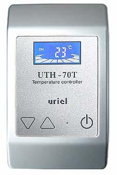
2 DISPLAY SCREENS AND FUNCTIONS DISPLAY SCREENS AND FUNCTIONS LCD DISPLAY SCREEN BAR DISPLAY: THIS DISPLAYS THE PRESENT STATE OF OUTPUT TO THE SIDE OF HEATER AS ON / OFF WHILE THE CONTROLLER IS WORKING. AS FIGURE, IF OUTPUT IS OFF, THE BAR OPERATION IN THE BOTTOM IS STOPPED WITH THE DISPLAY OF OFF ; IF OUTPUT IS ON, THE BAR OPERATION IS CONTINUED WITH THE DISPLAY OF ON. TEMP DISPLAY: WHILE THE PRIMARY SENSOR MODE IS WORKING, THE PRESENT TEMP IS DISPLAYED ON TEMP DISPLAY SCREEN ALL THE TIME. UNLESS OTHER KEY MOTION, THE PRESENT TEMP IS DISPLAYED, AND BY TOUCHING THE TEMP SET BUTTON (UP/DOWN), THE PRESENT SET TEMP IS DISPLAYED. WITH THE FIRST MOTION, THE SET TEMP IS DISPLAYED AND WITH ADDITIONAL TOUCH, THE SET TEMP GOES UP OR DOWN. BASIC MOTIONS POWER IS ON/OFF WITH POWER KEY AND IN CASE OF OFF, THE MOTIONS OF OTHER KEY AND CONTROLLER ARE SPENDED. UPON TOUCHING UP( ) OR DOWN ( ), THE DISPLAY OF BAR GRAPH IN THE BOTTOM IS DISAPPEARED AND INSTEAD OF IT, THE PRESENT SET TEMP IS DISPLAYED. IF THERE IS NO TOUCH FOR THREE (3) SECONDS AFTER SETTING A TEMP, THE PRESENT TEMP IS RECOVERED AND THE BAR GRAPH IN THE BOTTOM IS DISPLAYED. THE BUTTON IS OPERATED BY ONLY SOFT TOUCH WITH YOUR FIGURE. PLEASE PAY ATTENTION NOT TO TOUCH WITH OTHER MATTER EXCEPT THE FIGURE SINCE IT MAY NOT WORK. WHILE THE POWER BUTTON IS ON, IF THE CONTROLLER IS ON, THE SOUND OF BUZZER IS PRODUCED FOR TWO (2) TIMES AND IF OFF, THE SOUND FOR ONE (1) TIME: SUCH SOUND MAKES IT EASY TO DISTINGUISH ON AND OFF. PAY ATTENTION NOT TO TOUCH WITH OTHER KEY AT THE SAME TIME. INITIALIZATION FUNCTION THIS IS FOR RESETTING TO THE FUNCTION SET IN THE PLANT. IN CASE OF A WRONG SET OR AN ERROR MOTION OF CONTROLLER, THIS RESTORES ALL SET RANGE AND SET TEMP TO THE STATE SET IN THE PLANT. BY TOUCHING THE POWER BUTTON FOR ABOUT TEN (10) SECONDS, SAU FLICKERS FOR THREE (3) TIMES ON THE TEMP DISPLAY SCREEN AND ALL VALUES ON THE CONTROLLER IS CHANGED TO THE INITIAL ONES. (AT THE TIME OF SETTING INITIALIZATION, THE SENSOR MODE SET VALUE AND TIMER MODE VALUE ARE CHANGED TO THE INITIAL
3 SENSOR MODE MOTIONS AND HOW TO SET SENSOR MODE THIS MODE COMPARES THE PRESENT TEMP SENSED FROM THE SENSOR AND THE DESIRED TEMP (SET VALUE) AND CONTROLS THE GAP OF TEMPS BY POWER ON/OFF. HOW TO SET IN CASE OF ATTACHING THE SENSOR ON THE SENSE SPACE ON THE CONTROLLER AS THE BASIC MOTION METHOD, THE SENSOR IS SET AND WORKS AUTOMATICALLY. THE DETAILED SET IS POSSIBLE ADDITIONALLY. UPON TOUCHING UP( ) OR DOWN ( ) BUTTON FOR THREE (3) SECONDS SIMULTANEOUSLY, Stn, THE MENU THAT FUNCTION STARTS, IS DISPLAYED. IN THE MENU OF Stn, BY TOUCHING UP( ) BUTTON, THE MENU IS DISPLAYED IN THE ORDER OF SEn tin l.d. IN CASE OF DESIGNATING SEn ON THE DISPLAY SCREEN, TOUCH UP( ) OR DOWN ( ) BUTTON AT THE SAME TIME ONCE AGAIN. WHEN THE FINAL STAGE IS REACHED AFTER GOING THROUGH THE ABOVE PROCESS, THE MENU OF SAU FLICKERS FOR THREE (3) TIMES AND THE CHANGED SET VALUE IS SAVED. TERMINOLOGIES OF DISPLAY SCREEN AND EXPLANATION (SENSOR MODE) Sen t-l t-h dif dly Oht res SAU AS SENSOR MODE METHOD, THIS IS A BASIC MOTION MODE (BY USING THE TEMP DETECTION SENSOR, THIS WORKS BY COMPARING THE PRESENT TEMP AND THE SET TEMP). IN GENERAL USE, THIS HAS THE FUNCTION OF SETTING THE MINIMUM TEMP RANGE IN SETTING A DESIRED TEMP. THE SET OF MINIMUM TEMP IS POSSIBLE WITHIN THE RANGE OF THE MAXIMUM TEMP. IN GENERAL USE, THIS HAS THE FUNCTION OF SETTING THE MAXIMUM TEMP RANGE IN SETTING A DESIRED TEMP. THE SET OF MAXIMUM TEMP IS POSSIBLE WITHIN THE RANGE OF THE MINIMUM TEMP. THIS SETS THE TEMP DEVIATION SO THAT THE OUTPUT OF CONTROLLER MAY BE ON. IT IS RECOMMENDED TO DESIGNATE THE TEMP DEVIATION ACCORDING TO THE CIRCUMSTANCES OF CONTROLLER INSTALLATION. THIS SETS THE DELAY TIME TILL THE OUTPUT IS ON. THE DELAY TIME MAY EXERT AN INFLUENCE ON THE LIFE OF CONTROLLER, SO IT IS RECOMMENDED TO SET THE BASIC SET TIME TO BE TWENTY (20) SECONDS. IN CASE THAT THE TEMP DETECTED BY THE OVERHEATING SENSOR IS EXCEEDING THE SET TEMP, THIS FORCES THE OUTPUT OFF. (IN SETTING THE OVERHEATING TEMP, IT SHOULD BE DESIGNATED ABOVE THE MAXIMUM TEMP.) THIS IS A STANDARD RESISTANCE VALUE FOR IMPROVING THE PRECISION OF TEMP RANGE. IT IS RECOMMENDED TO CHANGE IN SPECIAL CASE. AFTER ALL SETS ARE COMPLETED ACCORDING TO THE ABOVE ORDER, SAU FLICKERS FOR THREE (3) TIMES AND THIS MACHINE WORKS ACCORDING TO THE CHANGED SET.
4 RANGE OF SET AND ERROR MESSAGE DUTY MOTION MODE SELECTION MINIMUM TEMP SET MAXIMUM TEMP SET TEMP DEVIATION SET DELAY TIME SET OVERHEATING TEMP SET BASIC RESISTANCE SET ERROR MESSAGE RANGE OF SET SENSOR MODE-TIMER MODE -9 ~UNDER THE MAX. TEMP OVER MIN. TEMP ~ ~05 01 SEC ~ 60 SEC OVER MAX. TEMP ~ ~10 BASIC SET IF ATTACHING SENSOR, SENSOR MODE, IF DISJOINING, TIMER ODE sec SNAPPING OF TEMP SENSING SENSOR IF TEMP SENSING SENOR IS SNAPPED, THE CONTROLLER IS CONVERTED TO TIMER MODE AUTOMATICALLY. (IN CASE THE PRESENT TEMP IS NOT DISPLAYED OR THE SET TEMP DOES NOT RISE OVER 10 WHILE USE THE TEMP MODE, THE CONTROLLER IS WORKING WITH TIMER MODE, SO CHECK WHETHER OR NOT THE SNAPPING OF TEMP SENSING SENSOR AT THE TIME OF EXTENSION OF TEMP SENSING SENSOR.) SHORT OF TEMP SENSING SENSOR IF SENSOR IS SHORT, THE OUTPUT OF CONTROLLER IS OFF AND ES IS DISPLAYED ON THE TEMP DISPLAY SCREEN WITH WARNING SOUND AND FLICKER. (SHORT IS OCCURRED FOR THE REASON OF BREAKDOWN OF SENSING SENSOR UNIT, SENSOR EXTENSION, ELECTRIC LEAKAGE IN THE SENSOR FIXING UNIT, SO CHECK IS NEEDED. AFTER ERROR RELEASES, AUTO RETURN), OVERHEATING ERROR IF OVERHEATING SENSOR TEMP IS EXCEEDING THE OVERHEATING SET TEMP, THE OUTPUT OF CONTROLLER IS OFF AND Oht IS DISPLAYED ON THE TEMP DISPLAY SCREEN WITH WARNING SOUND AND FLICKER. (CHECK THE STATE OF OVERHEATING SENSOR, CONTROLLER RELAY MOTIONS, ETC. IF OVERHEATING IS OCCURRED WHEN THE OVERHEATING SENSOR IS NOTFIXED, CHECK THE ELECTRIC LEAKAGE IN THE TEMP SENSOR UNIT OR CONFIRM THE SET TEMP VALUE. AFTER ERRORRELEASES, AUTO RETURN).
5 TIMER MODE MOTIONS AND HOW TO SET TIMER FUNCTION * IF WISH TO USE TIMER FUNCTION, MUST DISJOIN THE TEMP SENSOR. BY TOUCHING UP/DOWN KEY FOR 3 SEC SIMULTANEOUSLY, THE INITIAL Stn IS DISPLAYED. AT THIS TIME BY TOUCHING KEY ONCE AGAIN, THE MENU OF SEN IS DISPLAYED. SEN WORKS IN THE SAME METHOD TO THE SENSOR. BY TOUCHING SEN AGAIN, THE MENU OF tin IS DISPLAYED. AT THIS TIME BY TOUCHING UP ( ) AND DOWN ( ) KEY SIMULTANEOUSLY, THE PRESENT CYCLE VALUE IS DISPLAYED. WITH UP/DOWN KEY, SET THE CYCLE. BY TOUCHING UP ( ) AND DOWN ( ) KEY SIMULTANEOUSLY AND ONCE AGAIN, SAU FLICKERS, THE CYCLE VALUE IS SAVED, AND THE PRESENT SET STRENGTH IS DISPLAYED. HOW TO SET BY SEVICEMAN = PUSH UP ( ) AND DOWN ( ) KEY SIMULTANEOUSLY Stn DISPLAYS ON THE DISPLAY SCREEN SELECT tin- PUSH UP ( ) AND DOWN ( ) KEY SIMULTANEOUSLY DISPLAY THE CYCLE VALUE (CYCLE) SELECT CYCLE (BASIC UNIT: 3MIN.) - SET CYCLE VALUE - PUSH UP ( ) AND DOWN ( ) KEY SIMULTANEOUSLY - SAU FLICKERS SAVE COMPLETION (GIVE ATTENTION NOT TO BE SET BY A CONSUMER) HOW TO USE BY A CONSUMER= SELECT THE USE STRENGTH BY USING UP ( ) AND DOWN ( ) KEY (BASIC 1st STEP) * BASIC CYCLE: 3 MIN SETTING (CYCLE OPTION: RANGE OF 1MIN ~ 60MIN) * AFTER SELECTING CYCLE, BY TOUCHING UP ( ) AND DOWN ( ) KEY SIMULTANEOUSLY, SAU FLICKERS AND THE SET IS COMPLETED. (SERVICEMAN) * THE STRENGTH IS SELECTED BY CONSUMER IN THE DESIRED TEMP. (CONSUMER) * BASIC STEP IS THE 1st STEP SETTING (STRENGTH OPTION: RANGE OF 1st ~10th STEP) * PLEASE SELECT THE STRENGTH IN THE STATE THAT THERE IS NO SENSOR; IF JOINING THE SENSOR, IT SWITCHES TO THE SENSOR MODE IMMEDIATELY.
6 SET RANGE AND MOTION HOURS STEP OUTPUT(ON) OUTPUT(0FF) REMARK 1L 15 sec * S 45 sec * S 2L 3L 4L 5L 20 sec * S 25 sec * S 30 sec * S 35 sec * S 40 sec * S 35 sec * S 30 sec * S 25 sec * S S -> SELECTED CYCLE VALUE IF 1 MIN, S=1 IF 3 MIN, S=3 IF 5 MIN, S=5 * * (IF 20 MIN, S = 20, VALUE MULTIPLYING BY 20) (IF 60 MIN, S = 60, VALUE MULTIPLYING BY 60) 6H 40 sec * S 20 sec * S IT IS THE LENGTH OF ON AND OFF. 7H 45 sec * S 15 sec * S 8H 50 sec * S 10 sec * S 9H 55 sec * S 5 sec * S 10H 60 sec * S 0 sec * S

7 I.D. (HOW TO SET THE ROOM NUMBER) COMMUNICATION SET IN ORDER TO COMMUNICATE BETWEEN THE MAIN CONTROLLER FOR 128 CIRCUITS AND THE INDIVIDUAL CONTROLLER CORRESPONDING TO EACH ROOM NUMBER, IT IS NECESSARY TO SET I.D EACH OTHER. FIRST SET THE ROOM NUMBER ON THE MAIN CONTROLLER FOR 128 CIRCUITS, THEN SET EACH INDIVIDUAL CONTROLLER MATCHING TO THE MAIN CONTROLLER. HOW TO SET I.D FOR INDIVIDUAL CONTROLLER BY TOUCHING UP/DOWN KEY FOR 3 SEC SIMULTANEOUSLY, THE MENU OF Stn IS DISPLAYED. AT THIS TIME BY TOUCHING KEY ONCE AGAIN, THE MENU IS DISPLAYED IN THE ORDER OF SEn tin l.d. AFTER THE MENU OF i.d IS DISPLAYED, TOUCH UP/DOWN KEY SIMULTANEOUSLY ONCE AGAIN. THEN THE MENU FOR SETTING thn (THOUSAND UNIT) IS DISPLAYED. SET OF thn (THOUSAND UNIT): IN THE STATE OF SETTING thn, SET THE ROOM NUMBER OF THOUSAND UNIT WITH UP/DOWN KEY. IF WISHES TO SET HUNDRED UNIT OF ROOM NUMBER, SET 0 AND TOUCH UP/DOWN KEY SIMULTANEOUSLY ONCE. SET OF hnd (HUNDRED UNIT): IN THE STATE OF SETTING hnd, SET THE ROOM NUMBER OF HUNDRED UNIT WITH UP/DOWN KEY. IT IS POSSIBLE TO SET THE RANGE OF AFTER SETTING THE DESIRED ROOM NUMBER, TOUCH UP/DOWN KEY SIMULTANEOUSLY ONCE. SAU ON THE DISPLAY SCREEN FLICKERS AND THE SET OF ROOM NUMBER IS COMPLETED. MAKE SURE NOT TO DUPLICATE THE ROOM NUMBER. THERE MAY BE A RISK OF COMMUNICATION ERROR OR WRONG MOTION.
8 SPEC. CLASSI. Power unit ITEM Rated input voltage Output voltage Driving method Max output SPECIFICATIONS 85V AC ~ 265V AC (Universal voltage) 85V AC ~ 265V AC (Universal voltage) Electronic Type 3kw Loa d No. of circuit Max capacity 1 circuit 13A (Resistance load) precision Motion Temp precision Communication Method Output display Range of temp Output delay(option) ± 1 ; change condition of 1 per 30 sec (Delay Option 20 sec) 485 communication method, compatible to 232 communication method Bar motion on LCD Display Screen: ON display Possible to select within the range between -20 ~ sec ~ 60 sec Kind NTC : Negative Temperature Coeffcicent Epoxy molding Sensor Function (Capacity) Others Center- temp / R value 안전장치 Precision % Quantity Snapping/ Short of Sensor Line Overheating Prevention Sensor (OPTION) Resistance for fuse Outer case Weight Dimension (mm) 1 % 5000 ohm, Beta Constant = 4000 k SENSOR 1 : for sensing temp, SENSOR 2 : checking for overheating (Option) Snapping of temp sensing sensor: auto change to timer mode, short: ES (Error Short) displays, break the output, and buzzer The temp sensed in the overheating sensor is higher than that of set overheating temp: oht (Over Heat) display, break the output, and buzzer 10 ohm (protecting the inside circuit of controller) Anti-flammable 290g 70(W) * 120(H) * 45(D) Temp used. Air temp Air moisture 0 ~ 40 Under 80 %
9 CONNECTION DIAGRAM
UTH-170 Installation and Manual
 UTH-170 Installation and Manual Wiring Method #1 Method of Wiring Adhesion Wiring Method #2 Method of Wiring Adhesion Change of Function and Motions LAMP DISPLAY SET Lamp : This flickers at the time of
EPU-400 -THERMOSTAT MANUAL- ENERPIA CO., LTD
 EPU-400 -THERMOSTAT MANUAL- ENERPIA CO., LTD #349-13, Samunjin-Ro, Hwawon-Eup, Dalsung-Gun, Daegu, KOREA www.floorwarm.net info@enerpia.co.kr TEL : +82-53-474-8040 Fax: +82-53-473-8050 EPU-400 Installation
UTH-JP MANUAL 4 HOUR S/W: S/W FOR SETTING THE WATCH (HOUR), IN CASE OF RESERVATION, SET THE HOUR UNIT OF TIME
, IN CASE OF RESERVATION, SET THE HOUR UNIT OF TIME") UTH-JP MANUAL 1. S/W MOTIONS 1 POWER S/W: POWER S/W FOR ON/OFF OF CONTROLLER. 2 S/W : USE FOR UP THE SET TEMP. 3 S/W : USE FOR DOWN THE SET TEMP. 4 HOUR S/W: S/W FOR SETTING THE WATCH (HOUR), IN CASE OF
UTH-JP MANUAL 1. S/W MOTIONS 1 POWER S/W: POWER S/W FOR ON/OFF OF CONTROLLER. 2 S/W : USE FOR UP THE SET TEMP. 3 S/W : USE FOR DOWN THE SET TEMP. 4 HOUR S/W: S/W FOR SETTING THE WATCH (HOUR), IN CASE OF
ARC HEIGHT CONTROL (ARC VOLTAGE CONTROL) MODEL : HAC-01-A-1M
 MODEL : HAC-01-A-1M") ARC HEIGHT CONTROL (ARC VOLTAGE CONTROL) MODEL : HAC-01-A-1M 1. INTRODUCTION 1-1 Figures - It is a kind of unit to keep up Arc height between work-piece and torch by controlling the voltage of arc; if
ARC HEIGHT CONTROL (ARC VOLTAGE CONTROL) MODEL : HAC-01-A-1M 1. INTRODUCTION 1-1 Figures - It is a kind of unit to keep up Arc height between work-piece and torch by controlling the voltage of arc; if
SINGLE ZONE CLIMATE ZONING SYSTEM. Technical Manual. Polyaire Pty Ltd
 SINGLE ZONE CLIMATE ZONING SYSTEM Technical Manual Polyaire Pty Ltd 11-13 White Road GEPPS CROSS South Australia, 5094 Tel: (08) 8349 8466 Fax: (08) 8349 8446 www.polyaire.com.au CONTENTS Features 1 Application
Dimming actuators GDA-4K KNX GDA-8K KNX
 Dimming actuators GDA-4K KNX GDA-8K KNX GDA-4K KNX 108394 GDA-8K KNX 108395 Updated: May-17 (Subject to changes) Page 1 of 67 Contents 1 FUNCTIONAL CHARACTERISTICS... 4 1.1 OPERATION... 5 2 TECHNICAL DATA...
SM-10 SAT Level Meter User s Manual
 SM-10 SAT Level Meter User s Manual DAGATRONICS CORPORATION 263-1 DUCKIDONG, ILSAN, KOYANG, KYUNGKIDO, KOREA TEL: +82-31-916-8005 FAX: +82-31-916-8080 Email: dagatron@dagatron.com Website: www.dagatron.com
1.10mm Height 1210 Package. Bi-Color (Multi-Color) Chip LED. Technical Data Sheet. Part No: S155VBC-V12B-B41B
 Chip LED. Technical Data Sheet. Part No: S155VBC-V12B-B41B") .mm Height 2 Package Bi-Color (Multi-Color) Chip LED Technical Data Sheet Part No: S55VBC-V2B-B4B Spec No.: S55 Rev No.: V.3 Date: Jul.//25 Page: OF Features: Package in 8mm tape on 7 diameter reel. Bi-color
.mm Height 2 Package Bi-Color (Multi-Color) Chip LED Technical Data Sheet Part No: S55VBC-V2B-B4B Spec No.: S55 Rev No.: V.3 Date: Jul.//25 Page: OF Features: Package in 8mm tape on 7 diameter reel. Bi-color
Modular Lube Lubrication Systems System Controls
 Model 84501 Program Timer Solid State Designed to control the lubrication cycle frequency of air-operated single-stroke pumps. Timer turns pump on/off at programmed intervals via a 3-way or 4-way air solenoid
Dimming actuators of the FIX series DM 4-2 T, DM 8-2 T
 Dimming actuators of the FIX series DM 4-2 T, DM 8-2 T DM 4-2 T 4940280 DM 8-2 T 4940285 Updated: Jun-16 (Subject to change) Page 1 of 70 Contents 1 FUNCTIONAL CHARACTERISTICS... 4 1.1 OPERATION... 5 2
Solid-State Digital Timer
 Solid-State Digital Timer 1/16 DIN, Digital-Set Timer with 0.1 Second to 9,990 Hours Range 8 field-selectable operation modes Universal AC/DC supply voltage timers available Operations include ON-delay,
Multifunction Digital Timer
 Multifunction Digital Timer 72 x72 mm Timer with Easy-to-use Functions Nine output modes accommodate a wide variety of applications. All parameters set by scroll-through menus accessed from the front panel.
Technical Data Sheet 0805 Package White Chip LED
 Technical Data Sheet 0805 Package White Chip LED Features Package in 8mm tape on 7 diameter reel. Compatible with automatic placement equipment. Compatible with infrared and vapor phase reflow solder process.
IP Roombox. Hotel Room Management
 Hotel Room Management Hotel solutions Versatile room management system You need a simple solution which allows you to control all the hotel room electrical applications? Hager offers you a unique combination
Sample BD Tech Concepts LLC
 XYZ Corp. Fry Controller FC-1234 Operating Specification Copyright 2014 Brian Dunn BD Tech Concepts LLC Contents Last Modified: 00/00/0000 Introduction 2 Interface 3 Idle 5 Cooking Cycle 5 Displaying and
Features: Descriptions: Applications:
 Features: Package in 8mm tape on 7 diameter reel. Compatible with automatic placement equipment. Compatible with infrared and vapor phase reflow solder process. Mono-color type. The product itself will
Luminaire installation box Surface-mounted box Ceiling installation box
 -Smart PTM Ambient light sensor and motion detector for constant lighting control uminaire installation box Surface-mounted box Ceiling installation box Overview: -SMART PTM i is an ambient light sensor,
02/11/2015
 DIN Rail Mount 17.5 mm MUS/MUSF 80 AC/DC Part number 84872141 Control relays monitoring their own power supply - MUS : Over/undervoltage control Selectable latching (memory) function - MUSF : Over/undervoltage
Hardware & software Specifications
 Hardware & software Specifications Réf : PRELIMINARY JUNE 2007 Page 2 of 17 1. PRODUCT OVERVIEW...3 2. TERMINOLOGY...4 A. THE FRONT PANEL...4 B. THE REAR PANEL...5 3. SCREENS DESCRIPTION...5 A. MAIN SCREEN
User Manual CC DC 24 V 5A. Universal Control Unit UC-1-E. General Information SET. Universal Control Unit UC-1 Of Central Lubrication PAUSE CONTACT
 Universal Control Unit UC-1-E User Manual General Information Universal Control Unit UC-1 Of Central Lubrication CC DC 24 V 5A / M 15 SL /MK 31 M Z 30 General Information Contents Universal Control Unit
Luckylight Package Pure Green Chip LED. Technical Data Sheet. Part No.: S150PGC-G5-1B
 126 Package Pure Green Chip LED Technical Data Sheet Part No.: S15PGC-G5-1B Spec No.: S15 Rev No.: V.3 Date: Jul./1/26 Page: 1 OF 9 Features: Package in 8mm tape on 7 diameter reel. Compatible with automatic
Luckylight Package Warm White Chip LED. Technical Data Sheet. Part No.: S150W-W6-1E
 126 Package Warm White Chip LED Technical Data Sheet Part No.: S15W-W6-1E Spec No.: S15 Rev No.: V.3 Date: Jul./1/26 Page: 1 OF 11 Features: Package in 8mm tape on 7 diameter reel. Compatible with automatic
Luckylight. 1.10mm Height 0805 Package. Warm White Chip LED. Technical Data Sheet. Part No.: S170W-W6-1E
 1.1mm Height 85 Package Warm White Chip LED Technical Data Sheet Part No.: S17W-W6-1E Spec No.: S17 Rev No.: V.3 Date: Jul./1/26 Page: 1 OF 11 Features: Luckylight Package in 8mm tape on 7 diameter reel.
KNX Dimmer RGBW - User Manual
 KNX Dimmer RGBW - User Manual Item No.: LC-013-004 1. Product Description With the KNX Dimmer RGBW it is possible to control of RGBW, WW-CW LED or 4 independent channels with integrated KNX BCU. Simple
Gamma instabus. Technical product information
 Gamma instabus Technical product information Universal dimmer N 554D31, 4 x 300 VA / 1x 1000 VA, AC 230 V Universal dimmer N 554D31 Control of dimmable lamps, including LED without minimum load Output
FRQM-2 Frequency Counter & RF Multimeter
 FRQM-2 Frequency Counter & RF Multimeter Usage Instructions Firmware v2.09 Copyright 2007-2011 by ASPiSYS Ltd. Distributed by: ASPiSYS Ltd. P.O.Box 14386, Athens 11510 (http://www.aspisys.com) Tel. (+30)
26 Inch CGA/EGA/VGA/DVI to WXGA/1080p LCD - ID#703
 26 Inch CGA/EGA/VGA/DVI to WXGA/1080p LCD - ID#703 Operation Manual Introduction This monitor is an open frame LCD Panel monitor. It features the VESA plug & play system which allows the monitor to automatically
Technical Data Sheet White SMD Surface Mount Device
 Technical Data Sheet White SMD Surface Mount Device Features Fluorescence Type High Luminous Intensity High Efficiency Emission Color:x=0.29,y=0.30 Descriptions The white LED which was fabricated using
TRANSCENSION 6-CHANNEL DMX DIMMER PACK (order code: BOTE40) USER MANUAL
 USER MANUAL") www.prolight.co.uk TRANSCENSION 6-CHANNEL PACK (order code: BOTE40) USER MANUAL SAFETY WARNING FOR YOUR OWN SAFETY, PLEASE READ THIS USER MANUAL CAREFULLY BEFORE YOUR INITIAL START-UP! CAUTION! Keep this
www.prolight.co.uk TRANSCENSION 6-CHANNEL PACK (order code: BOTE40) USER MANUAL SAFETY WARNING FOR YOUR OWN SAFETY, PLEASE READ THIS USER MANUAL CAREFULLY BEFORE YOUR INITIAL START-UP! CAUTION! Keep this
Sequential and Combination Timer TK-415 with RS-232 communication
 NOVATEK-ELECTRO LTD. Sequential and Combination Timer TK-415 with RS-232 communication OPERATION MANUAL WWW.NOVATEK-ELECTRO.COM/EN 2011 1. GENERAL PROVISIONS 1.1. BASIC FUNCTIONS - microprocessor controlled.
DGC-1000A CLAMP-ON GROUND RESISTANCE TESTER
 DGC-1000A CLAMP-ON GROUND RESISTANCE TESTER USERS MANUAL HOLD OFF FUNC REC For detailed specifications and ordering info go to www.testequipmentdepot.com EN 61010-2-032 CAT III 300V, CAT II 600V Pollution
Operating instructions Electronic preset counter Type series 717
 Operating instructions Electronic preset counter Type series 717 1. Description 5.98.3_gb 6-digit adding/subtracting counter with two presets Very bright 8mm high LED display Counting and preset range
Automatic Transfer Switch Control PLC Operator s Manual
 MTS Power Products MIAMI FL 33142 ATS-22AG Automatic Transfer Switch Control PLC Operator s Manual Dedicated Single Phase Transfer Switch ATS-22AG Automatic Transfer Switch INTRODUCTION 1.1 Preliminary
Model Number Structure
 Cycle Control Units CSM DS_E_7_1 Refer to Safety Precautions for All Power Controllers. Used in Combination with the to Enable High-precision Temperature Control Use cycle control to achieve power control
Dynamic Cable Rating Model Guidelines
 lines Introduction This document describes how to set up, configure and run the Dynamic Cable Rating model in Ipsa. The Dynamic Cable Rating model (DCR) has been developed for the WPD FALCON project by
3mm Round White LED T-1. Technical Data Sheet. Part No: LL-304WC2E-W2-3TC
 3mm Round White LED T-1 Technical Data Sheet Part No: LL-304WC2E-W2-3TC Spec No: UP302 Rev No:V.1 Date:Feb/16/2004 Page: 1 OF 8 Features Popular T-1 diameter package High efficiency Selected minimum intensities
LED Driver Compact fixed output
 Driver LC 40W 900mA fixc C SNC ESSENCE series Product description Fixed output built-in LED Driver Constant current LED Driver Output current 900 ma Max. output power 40 W Nominal life-time up to 50,000
PBC series. RoHS. Ready. IEC-Type Contactors & Accessories 9-80 Amp AC-3, Amp AC-1 AC Coils. P&B PBC Series IEC Type Contactors & Accessories
 PBC series IEC-Type Contactors & Accessories 9-80 Amp AC-3, 25-125 Amp AC-1 AC Coils File E38802 (PBC) RoHS Ready Users should thoroughly review the technical data before selecting a product part number.
Installation Instructions
 Installation Instructions Product Functional Details Overdrive ODMR0210 Dimmer + Controller Overdrive Dimmer Controller with MOSFET control provides the finest dimming for low light levels and strong lamp
LM-TV09-4K2K. 4K video wall controller. User. Manual
 LM-TV09-4K2K 4K video wall controller User Manual Catalog 1.Installation Instructions 1 2.Product Brief 2 3.Controller Installed 3 4.Remote Control Settings 6 5.Pressing Setting 7 6.Specifications 7 1
This document is a reference document that shows the menus in the 5500sc, 9610sc and 9611sc analyzers. There are 3 top-level menus:
 Controller menus 5500sc, 9610sc and 9611sc analyzers DOC273.53.80566 Introduction This document is a reference document that shows the menus in the 5500sc, 9610sc and 9611sc analyzers. There are 3 top-level
Figure 1: Device components
 Order No. : 2860 10 Order No. : 2830 10 Operation- and Assembly Instructions 1 Safety instructions Electrical equipment may only be installed and fitted by electrically skilled persons. Failure to observe
Weekly Time Switch. Rated time Time setting range Time division 24 hrs x 7 days 00:00 to 23:59 1min
 Weekly Time Switch Easy Programming with Large LCD Display and Interactive Functions Programming for 24 hrs x 7 days using just five switches. Sixteen program steps available. Power supply freely selectable
T +31 (0) F
 F") Thomas Feed is a computer for the control of a dry feed system that is used to give all of your animals ad-lib feeding. This computer is exceptionally easy to use. Icons on the large screen show the available
Thomas Feed is a computer for the control of a dry feed system that is used to give all of your animals ad-lib feeding. This computer is exceptionally easy to use. Icons on the large screen show the available
LED Driver Linear / area fixed output
 Driver LC 10W 350mA fixc lp SNC2 ESSENCE series Product description Fixed output built-in LED Driver Constant current LED Driver Output current 350 ma Max. output power 10.2 W Up to 80 % efficiency For
Technical Data Sheet 0603 Package Chip LED (0.4mm Height)
") Technical Data Sheet 0603 Package Chip LED (0.4mm Height) Features Package in 8mm tape on 7 diameter reel. Compatible with automatic placement equipment. Compatible with infrared and vapor phase reflow
Technical Data Sheet 0603 Package Chip LED (0.4mm Height) Features Package in 8mm tape on 7 diameter reel. Compatible with automatic placement equipment. Compatible with infrared and vapor phase reflow
Digital output modules
 Appendix 374 Digital output modules Order number Figure Type DO 8xDC 24V 2A DO 16xDC 24V 1A DO 16xDC 24V 2A DO 16xDC 24V 0.5A manual operation General information Note - - - - Features 8 outputs, in groups
Innovative Air Systems ABN When Calling For Support Quote:.doc
 1.0 User Guide 1.1 Normal Display This displays the current time and date. 1.2 Condition On Press the button to turn on the air conditioning. If the After Hours Timer is set then the air conditioning
PHASED OUT. LED control gear Compact fixed output. Driver LC 40W 900mA fixc C SNC China Domestic ESSENCE series
 Product description Fixed output built-in LED Driver Constant current LED Driver Output current 900 ma Max. output power 40 W Nominal life-time up to 30,000 h For luminaires of protection class I and protection
Instruction Manual for Programmable Digital Timer
 Instruction Manual for Programmable Digital Timer Item No.: EMT757 A. Functions 1. The Programmable Digital Timer (hereinafter refer as Timer ) can preset specific on/off time of your home electrical appliances.
Software Manual Control Panel for Professional Single Booster Units Models: MM3 BW3
 Software Manual Control Panel for Professional Single Booster Units Models: MM3 BW3 EN Software Manual.. 1-14 1 1. DESCRIPTION 3 2. DISPLAY LAYOUT 4 3. MODES 5 3.1 Power On 5 3.2 Standby 5 3.3 Power off
Acer LCD TV AT2001 User's Guide
 Acer LCD TV AT2001 User's Guide Copyright 2005. Acer Incorporated. All Rights Reserved. Acer AT2001 User' s Guide Original Issue: May 2005 Acer and the Acer logo are registered trademarks of Acer Incorporated.
LED Driver Compact fixed output
 Driver LC 45W 1050mA fixc C SNC ESSENCE series Product description Fixed output built-in LED Driver Constant current LED Driver Output current 1,050 ma output power 45 W Nominal life-time up to 50,000
Sample BD Tech Concepts LLC
 XYZ Corp. Fry Controller FC-1234 Software Test Procedure Copyright 2014 Brian Dunn BD Tech Concepts LLC Last Modified: 00/00/0000 Version Tested: Date Tested: Technician: Results: 1 FC-1234 SW Test Proc.
TOSHIBA Industrial Magnetron E3328
 TOSHIBA E3328 is a fixed frequency continuous wave magnetron intended for use in the industrial microwave heating applications. The average output power is 3kW in the frequency range from 2450 to 2470
WELD OSCILLATOR MODEL : HTW-05-AN
 WELD OSCILLATOR MODEL : HTW-05-AN 1. OUTLINE - It is a mechanical oscillator to get the following welding; 1) To get the bead clean and uniformed. 2) To get the penetration uniformed. 3) It is a proper
TriLIN Program Utility TPU_ TriLIN Programming Manual
 Program Utility TPU_2.8.2 TriLIN Programming Manual 1. Programming the electronics a. Tool necessary Power supply 12-32 V DC Computer with appropriate USB port and a Windows Operating System (We recommend
2 2 Relay outputs. M DIN W72 H7mm. LE7 Weekly/Yearly timer
 LE7M-2 W72 H72mm, Weekly/Yearly Timer Features Easy to check and change the program setting Customizable weekly or yearly unit time setting and control by user Includes daylight saving time function Built-in
DIGISAT MULTI USER MANUAL
 DIGISAT MULTI USER MANUAL CONTENTS: Meter specifications page 3 Accessories included page 3 Description page 4 Charging the batteries page 5 Controls and Features page 6 Hi Resolution Mode page 7 Audio
Radio Thermostat Clock
 Radio Thermostat Clock Installation & User Instructions Part number: ZU0800009 80.10.1375.7_feeling_ks_fer_en.indd 1 18.04.2013 11:25:42 Table of contents Safety instructions... 3 Product details... 4
GC30 Digital Differential Pressure Gauge Operation Manual
 TY-GC30-001A GC30 Digital Differential Pressure Gauge Operation Manual NAGANO KEIKI CO., LTD 2004.02.12 For safety of use TY-GC30-001A In order to safely and correctly utilize this device, please read
LED control gear Compact dimming. Uconverter LCAI 2x38 W 0500 K013 one4all ECO series. Ordering data
 Product description Dimmable built-in for LED Constant current (with 2 adjustable output channels) Designed for outdoor and street luminaire Output power 2 x 38 W Suitable for mains voltage peaks (burst/surge)
17 19 PROFESSIONAL LCD COLOUR MONITOR ART
 17 19 PROFESSIONAL LCD COLOUR MONITOR ART. 41657-41659 Via Don Arrigoni, 5 24020 Rovetta S. Lorenzo (Bergamo) http://www.comelit.eu e-mail:export.department@comelit.it WARNING: TO REDUCE THE RISK OF FIRE
DCP100 Digital Control Programmer Specifications
 DCP100 Digital Control Programmer Specifications EN01-6028 October 1996 Overview The DCP100 is a microprocessor based 1 /4 DIN programmer/controller for process variable versus time control of temperature,
INSTRUCTION & OPERATION MANUAL. MODEL MMW-05 (5kW) MUROMACHI MICROWAVE FIXATION SYSTEM
 MUROMACHI MICROWAVE FIXATION SYSTEM") INSTRUCTION & OPERATION MANUAL MODEL MMW-05 (5kW) MUROMACHI MICROWAVE FIXATION SYSTEM MUROMACHI KIKAI CO., LTD. TOKYO PRECAUTIONS The Microwave Fixation System is developed to rapidly halt brain chemical
INSTRUCTION & OPERATION MANUAL MODEL MMW-05 (5kW) MUROMACHI MICROWAVE FIXATION SYSTEM MUROMACHI KIKAI CO., LTD. TOKYO PRECAUTIONS The Microwave Fixation System is developed to rapidly halt brain chemical
Datasheet - SRB301LC 24VAC/DC
 25.02.2016-18:05:23h Datasheet - SRB301LC 24VAC/DC Guard door monitors and Safety control modules for Emergency Stop applications / General Purpose safety controllers (Series PROTECT SRB) / SRB301LC Preferred
2000 W, 2450 MHz Microwave Generator GMP 20K SM 56M230 FST 3 IR
 2000 W, 2450 MHz Microwave Generator GMP 20K SM 56M230 FST 3 IR Power supply It is based upon the latest switch mode power supply technology, offering size reduction (i.e. 19 rack, 3U power supply), good
MODEL 5493A DTMF MODEM
 USER S GUIDE MODEL 5493A DTMF MODEM SIGNALCRAFTERS TECH, INC. 57 Eagle Rock Avenue, East Hanover, NJ 07936 Tel: 973-781 - 0880 or 800-523 - 5815 Fax: 973-781 - 9044 http://www.signalcrafters.com 01/07/2009
24 Hour & 7 Day Digital Immersion Heater Timeswitch Article
 24 Hour & 7 Day Digital Immersion Heater Timeswitch Article 943 320 Large 24 hour clock/programme display. Tough flame retardant bezel 1 Enables clock time to be changed. Used to review and change timer
2 2 Relay outputs. M DIN W72 H7mm. LE7 Weekly/Yearly timer
 Weekly/Yearly Timer W72 H72mm, Weekly/Yearly timer Features Easy to check and change the program setting Customizable weekly or yearly unit time setting and control by user Includes daylight saving time
Electronic Timer Control Day Astronomic Electronic Control
 Electronic Timer Control - 365-Day Astronomic Electronic Control Item ET90215CRE / EAN-Code PRODUCT DESCRIPTION The ET90000 Series combines powerful and intuitive scheduling with truly maintenance-free
UK. Multi Channel Programmable Filter-Equalizer. User Manual FEATURES. - Designed for both digital and analogue channels,
 Multi Channel Programmable Filter-Equalizer User Manual 6506 6506UK FEATURES - Designed for both digital and analogue channels, - 2 UHF input / 1 output, - 8 programmable clusters, - UHF channels 21 to
Quick Start Operating Instructions
 Table of Contents 1. Introduction 1 2. Instrument Controls & Indicators 2 3. Digital Display and Screens Overview 3 4. Setting the Basic Operating Level 4 5. Calibration 6 A The Calibration Menu: Screen
USER & ENGINEER INSTRUCTION MANUAL
 USER & ENGINEER INSTRUCTION MANUAL BENSON CP4 USER INSTRUCTIONS CONTENTS PAGE SUBJECT PAGE No. Contents Page... 1 CP4 Basic Setting Guide... 2-3 Standard Terms... 4 Normal RUN Mode... 4 Override... 5
Preset Counters. X e. X d 6.92 X. 0. IP khz Batch. LCD Preset Counters 1, 2, 4 or 6 Presets. Multifunction. Fast and user-friendly
 The Codix 923/924 can be used universally. As a preset pulse counter, tachometer or preset timer with up to 6 presets it is able to solve a very wide range of control and monitoring tasks in every application.
K-BUS Dimmer Module User manual-ver. 1
 K-BUS Dimmer Module User manual-ver. 1 KA/D0103.1 KA/D0203.1 KA/D0403.1 Content 1. Introduction... 3 2. Technical Parameter... 3 3. Dimension and Connection Diagram... 4 3.1 KA/D0103.1... 4 3.2 KA/D0203.1...
multi-function meters
 multi-function meters eclipse 2 eclipse 7 installation and operating manual 1 GENERAL DESCRIPTION 2 INSTALLATION 3 WIRING INFORMATION 4 2 ECLIPSE 2 METERS 2.1 PROGRAMMING THE METER 5 2.2 INFORMATION 6
Getting started with
 Getting started with Electricity consumption monitoring single phase for homes and some smaller light commercial premises OVERVIEW: The OWL Intuition-e electricity monitoring system comprises of three
Series CT7N Bimetallic Overload Relays
 Series CT7N imetallic Overload Relays Choose CT7N overloads in DC applications and when monitoring Variable Frequency Drives Sprecher + Schuh has always paid particular attention to the subject of motor
BooBox Flex. OPERATING MANUAL V1.1 (Feb 24, 2010) 6 Oakside Court Barrie, Ontario L4N 5V5 Tel: Fax:
 6 Oakside Court Barrie, Ontario L4N 5V5 Tel: Fax:") BooBox Flex OPERATING MANUAL V1.1 (Feb 24, 2010) 6 Oakside Court Barrie, Ontario L4N 5V5 Tel: 905-803-9274 Fax: 647-439-1470 www.frightideas.com Connections The BooBox Flex is available with Terminal Blocks
BooBox Flex OPERATING MANUAL V1.1 (Feb 24, 2010) 6 Oakside Court Barrie, Ontario L4N 5V5 Tel: 905-803-9274 Fax: 647-439-1470 www.frightideas.com Connections The BooBox Flex is available with Terminal Blocks
LED Driver Linear / area dimming industry. Driver LC 200W 1050mA UNV ADV IND ADVANCED series
 Driver LC 200W 1050mA UNV ADV IND ADVANCED series Product description Independent constant current LED Driver For dry, damp and wet locations Max. output power 200 W Up to 93.7 % efficiency For luminaires
15 Inch CGA EGA VGA to XGA LCD Wide Viewing Angle Panel ID# 833
 15 Inch CGA EGA VGA to XGA LCD Wide Viewing Angle Panel ID# 833 Operation Manual Introduction This monitor is an open frame LCD Panel monitor. It features the VESA plug & play system which allows the monitor
17" & 19" Color TFT LCD Monitor
 17" & 19" Color TFT LCD Monitor KMC-17B & KMC-19B User's Manual for Operation and installation Screen Size : KMC-17B (17" inch TFT LCD) KMC-19B (19" inch TFT LCD) Display Size : KMC-17B (337.920mm X 270.336mm)
Single output models feature wide-range output adjustability to meet a wide variety of standard and user-specific output voltage requirements.
 RoHS Lead-Solder-Exemption Compliant New 3.3 V and 5 V Output Models Universal Input 85-264 VAC Industry-Standard Footprint: 7.0" x 4.3" x 1.97" (177.8 x 109.2 x 50.0 mm) Input Transient & ESD Compliance
Filter Control FS-201
 Filter Control FS-201 1/33 Index 1 General Information...4 1.1 Equipment...4 2 Installation...5 2.1 Mechanical Installation...5 2.2 Electrical Installation...5 2.2.1 Connection Diagram...6 3 Operation...6
Sensor module. Safety instructions. Function Correct use. Product characteristics. Structure of the device. Operation. Ref.No.
 Sensor module Ref.No.: SM 1608 V03 Safety instructions Caution! Electrical devices may only be installed and fitted by electrically skilled persons. Non-compliance with the installation information could
OWNER S MANUAL MOTORIZED 7 WIDE TFT LCD COLOR MONITOR CNT-701
 OWNER S MANUAL PW MOTORIZED 7 WIDE TFT LCD COLOR MONITOR CNT-701 ANY CHANGES OR MODIFICATIONS IN CONSTRUCTION OF THIS UNIT DEVICE WHICH IS NOT APPROVED BY THE PARTY RESPONSIBLE FOR COMPLIACE COULD VOID
Weekly Timer. Mounting track 50 cm (1.64 ft) length PFP-50N 1 m (3.28 ft) length PFP-100N
 length PFP-50N 1 m (3.28 ft) length PFP-100N") Weekly Timer 1/4 DIN Size Timer Features Prompted Programming and Large LCD Display 24 hours x 7 days programming using just 5 switches 16 program steps and cycle operation Two independent 15 A control
Weekly Timer 1/4 DIN Size Timer Features Prompted Programming and Large LCD Display 24 hours x 7 days programming using just 5 switches 16 program steps and cycle operation Two independent 15 A control
Technical Data Sheet 0805 Package Chip LED (0.8mm Height)
") Technical Data Sheet 0805 Package Chip LED (0.8mm Height) Features Package in 8mm tape on 7 diameter reel. Compatible with automatic placement equipment. Compatible with infrared and vapor phase reflow
Technical Data Sheet 0805 Package Chip LED (0.8mm Height) Features Package in 8mm tape on 7 diameter reel. Compatible with automatic placement equipment. Compatible with infrared and vapor phase reflow
Time-Lag Relays. User s Handbook (General Model)
") Time-Lag Relays User s Handbook (General Model) 651.601.387 Rev: V39 Date: 09/2016 Electrotécnica Arteche Smart Grid, S.L. This document, including texts, photos, graphics and any other content, is protected
Time-Lag Relays User s Handbook (General Model) 651.601.387 Rev: V39 Date: 09/2016 Electrotécnica Arteche Smart Grid, S.L. This document, including texts, photos, graphics and any other content, is protected
EVERLIGHT ELECTRONICS CO.,LTD.
 Technical Data Sheet 1206 Package Chip LED with Inner Lens Features Package in 8mm tape on 7 diameter reel. Compatible with automatic placement equipment. Compatible with infrared and vapor phase reflow
PQ-Box 100 Quick Start Instructions
 PQ-Box 100 Quick Start Instructions These instructions are provided for the purpose on providing a quick start to PQ-Box 100 installation and operation. Please refer to the user handbook for full details.
Ordering details. Approval. Classification
 Datasheet - SRB 301MC-24V Guard door monitors and Safety control modules for Emergency Stop applications / General Purpose safety controllers (Series PROTECT SRB) / SRB 301MC Fit for signal evaluation
Bimetal Temperature Switch
 Phone: +44 19 635533 Fax: +44 19 635262 Data sheet 608301 Page 1/8 Bimetal Temperature Switch Special features Electromechanical temperature switch with a fixed switching temperature Protection type IP52,
3mm Round Blue LED T-1 Technical Data Sheet
 3mm Round Blue LED T-1 Technical Data Sheet Model No: LL-304BC2E-B4 Spec No:U302B41E Rev No:V.2 Date: Nov/15/2001 Page: 1 OF 7 Features Popular T-1 diameter package High efficiency Selected minimum intensities
Model IQ4-PC User Manual Revision Date:
 Basic Specifications Supply Volts 230V 50/60Hz ±15% 115V 50/60Hz ±15% 24V DC (isolated) ±15% Power Consumption Max. 3VA (IQ4-PC-R0) Max. 6VA (IQ4-PC-R2-PSI24-RT) Operating Temperature -5 ~ +60 C Operating
12.1 Inch CGA EGA VGA SVGA LCD Panel - ID #492
 12.1 Inch CGA EGA VGA SVGA LCD Panel - ID #492 Operation Manual Introduction This monitor is an open frame LCD Panel monitor. It features the VESA plug & play system which allows the monitor to automatically
Dimmers SЕRIES. Kitchen light control. Bedroom light control. Living room light control
 Kitchen light control Bedroom light control 15 SЕRES iving room light control ighting control in corridors (for hotels, offices and hospitals) FDER reserves the right to alter characteristics at any time
Synchronization Check Relay ARGUS 7
 Synchronization Check Relay ARGUS 7 Page 1 of 8 Table of Contents Secondary injection tests:... 3 Phase Angle Test:... 3 CS PHASE ANGLE:... 3 SS PHASE ANGLE:... 3 SLIP FREQUENCY TEST:... 4 CS SLIP FREQUENCY:...
Tebis TX100 Configurator
 5 Tebis TX100 Configurator quicklink Radio input products Electrical / Mechanical characteristics: see product user's instructions Product reference Product designation TX100 version TP device RF device