ARC HEIGHT CONTROL (ARC VOLTAGE CONTROL) MODEL : HAC-01-A-1M
|
|
|
- Elmer Owen
- 5 years ago
- Views:
Transcription

 MODEL")
1 ARC HEIGHT CONTROL (ARC VOLTAGE CONTROL) MODEL : HAC-01-A-1M
2 1. INTRODUCTION 1-1 Figures - It is a kind of unit to keep up Arc height between work-piece and torch by controlling the voltage of arc; if the voltage difference occurs between the setting value in the control and the real voltage from the torch, the slide does move up and down to keep up the distance or gap between the torch and work-piece. - When the welding is in the process, the voltage gets changed according to the distance between the torch and work-piece. Therefore, the slide does work on not to be out of the set point. - The unit is compatible to the other system for automation by using the connectors. 1-2 Function Explanation 1) The LCD and full digital control are applied for easy control and handling. 2) There are the applicable process; GTAW(TIG), PAW(PLASMA), PACT(PLASMA cutting). 3) In case of GTAW(TIG), the tungsten electrode does touch the work-piece and then the torch automatically moves up. So, the start position setting is easy. 4) For the interface to the other utilities, there is the connector on the unit. On the top of that, the user can apply to some other welding conditions by changing the parameters. Function easy to use In the Auto mode or manual mode, when the arc height is not suitable for the welding, the height can be adjusted with the following manual s/w and in addition the welding parameters or conditions can be also newly programed or set. ACTUATOR - The slider mounted with the torch can be moved up and down with the actuator button. - During the operating or welding, the torch can be adjusted up or down with the button. At the moment when the button is off, the Arc Voltage supplied at the height of the torch is automatically saved as standard voltage
3 1-3 Pre-condition. - As follows are the check-points before the user applies the unit; 1) The power voltage is not fluctuated too much. 2) There should be almost no contact resistance inside/outside the welding machine. 3) There should be almost no contact resistance according to the temperature rising in the inside of the welder and the contact resistance of cables connecting to torch or workpiece. (please check the worn-out of the parts or if the cable length is changed) 4) Make sure the sensor is correctly connected to the power source. (The power source for GTAW may be not connected to the sensor according to the manufacturer of the power source) 5) It is important to keep the welding travel speed even. If the travel speed is not even, the same Arc voltage make the height of the torch not even. For example, the welding conditions is as follows: the Arc voltage 15V, travel speed 500mm/min, 5mm height of the torch. If the welding speed is slow, the arc voltage and the height of the torch go up. On the contrary, the fast travel makes the arc voltage low and the torch down
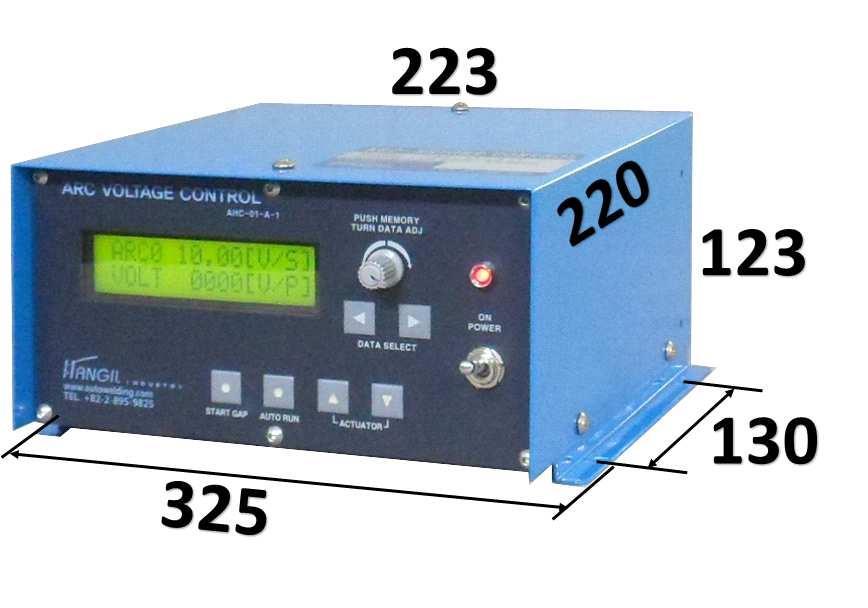
4 1-4 INSTALLATION - 3 -


5 ( ) SIZE = SLIDE MODEL HS
6 2. STANDARD SPECIFICATION DESCRIPTION APPLICATION HAC-01-A-1M GTAW, PAW, PACT (DC) CONTROL Welding Parameter Programmable : 10models( ) 1) Process 2) Standard voltage range selection 3) Voltage-setting range 4) Standard deviation setting range 5) STICK OUT length setting range GTAW, PAW, PACT (Only DC ARC WELDING) But, the pulse welding is available when there is the pulse-synchronous signal AVG : the current ARC voltage is automatically memorized AUTO : The welding voltage com be input in the number ANL : The voltage can be set from external equipment GTAW, PAW : 5 ~ 50V PACT : 50 ~ 500V GTAW, PAW : 0.05 ~ 2.55V PACT : 0.5 ~ 25 V 0.1 ~ 10mm 6) START DELAY TIME 0.0 ~ 9.9sec. 7) Standard voltage : auto memory time 0.0 ~ 9.9sec. 8) Output Delay Time 0.0 ~ 1.0sec 9) Pull up range setting 0.0 ~ 50mm 10) Up/down speed 0.1 ~ 99% GTAW, PAW HS (HS ) MOTORIZED SLIDE SENSOR (AVC) CABLE FOR CONNECTING Loading capacity Stroke Moment Speed Motor Pact GTAW, PAW PACT HAC-CABLE-03 : 5(10)kg : 100(140)mm : 70(180)kg-cm : 100(150)mm/min. : stepping motor : option and on request. : HAD-01-QV-50 : HAD-01-QV-500 POWER CABLE 1Ø, 220V, 50/60Hz, 2A - 5 -
7 3. COMPONENTS 3-1 COMPONENT UNIT 1) CONTROL BOX 1SET 2) UP/DOWN SLIDE 1SET 3) SENSOR (AVC) 1SET 4) CONNETING CABLE 1SET (POWER, SLIDE, SENSOR) - 6 -
8 4. EXPLANATION ON UNIT 4-1 Control Unit - During the welding, the sensor does check the change of arc voltage and does compare the setting voltage with the change range. The slide on which the torch is mounted does move up/down so that the established arc voltage can meet with the welding arc voltage. - This control can memorize various parameters to require the operation. - Welding Parameter programmable: max 5 models. 4-2 Motorized Slide - The frame is made of Al and for the precision of the slide, ball screw is used and the limit S/W is attached to the stroke ends. 4-3 Voltage Sensor 1) The ARC voltage sensor can perceive the change of the welding ARC voltage. We use HAD-01-QV as a sensor. (The end-user shall discuss the specification of GTAW welding machine, its type and its brand with Hangil engineer) 2) Plasma Arc Cutting(PACT) shall use the sensor for HAD-01-QV-PACT only

.")
9 5. EXPLANATION ON Function Switch Power S/W - The switch is for supply of the power to the control unit. ACTUATOR - The slider mounted with the torch can be moved up and down with the button. - During the operating or welding, the torch can be adjusted up or down with the actuator button. At the moment when the button is off, the Arc Voltage supplied at the height of the torch is automatically saved and memorized as standard voltage. AUTO RUN - This function can work regardless of START GAP. - The function does work as per setting parameters (0-10). - When the button S/W is on, the distance keeps between the torch and workpiece by moving the slider up or down according to the setting voltage and real voltage (the welding Arc voltage keeps during the operation). At this time, if Relay is on and then the S/W is off, off. - RELAY2 can be used for connector of welder for automation: on or off START GAP - When the button s/w is ON, the Slider moves down at first and then the tungsten touch the workpiece, and stop at the setting value: STICK OUT in SCREEN 5. Stand by AUTO RUN or BUTTON ON - If STICK OUT is finished, the RELAY 1 is ON. It can be connected to the other Automatic Sys - 8 -


 MC OUT connector - It is for connector to other system or for interface.")

 MEMORY - It is a connector to select the memorized data from external equipment.")
10 DATA ADJUST and MEMORY S/W (TURN DATA ADJUST/ PUSH MEMORY) - his rotary encoder(pmtda) is for setting and saving of the parameters. The clockwise is rotated increase and ccw decrease. - Push one time to save when the settings are finished - The setting value(data) is saved by pushing one time and then the Cursor disappear! LCD DATA SCREEN Change button - It is the button of change of SCREEN. - When the button is push ON, the SCREEN is changed. Other Connectors - There are connectors in the right of control for external equipment. 1) MC OUT connector - It is for connector to other system or for interface. - It has RELAY 1,2 contact point. -The external equipment or system can read and use the setting welding parameters. -For the details, please refer to the drawing herein. 2) MEMORY - It is a connector to select the memorized data from external equipment. - The Memory 1-10(welding model) can be selected, be made in combination of ) SENSOR connector - It is the connector to ARC VOLTAGE SENSOR. 4) REMOTE connector -It is the Remote for control, auto run, manual slider moving up/down. 5) SLIDE connector for up/down - 9 -
11 LCD SCREEN DISPLAY setting and explanation. - It is the display Screen to input the setting value(or data) or correct the established data. SCREEN 4. Standard Voltage setting and operating mode selecting 1 > A V E O P - M O D E 2 > A U T O 3 > A N L [ 1 ] - It is display screen to set the standard voltage or operating mode. - If [1] is selected, the screen 1 is displayed in the Screen1-1 - If [2] is selected, the screen 2 is displayed in the Screen1-1 - If [3] is selected, the screen 3 is displayed in the Screen1-1 - The operator rotates the PUSH MEMORY TURN DATA ADJ for adjusting the data(value) and then push it one time for memory setting. - The Cursor will disappear when to push for memory setting. SCREEN 1-1. Initial Screen 1(Arc Voltage AVE selection Mode) It is the screen for welding standard setting and welding Arc voltage meter. A R C +??.?? [ V / S ] V O L T [ V / P ] - From 1>AVE 2>AUTO 3>ANL in the screen 4 If 1>AVE is selected, it is displayed like the screen 1. - During welding, the screen is displayed below. - The following screen is displayed when welding arc voltage is 10.00V. A R C [ V / S ] V O L T [ V / P ] - From 1>AVE > 2>AUTO 3>ANL in the screen 4 If 1>AVA, or 3>ANL is selected, the memorized (or saved) data cannot be used. - The set or memorized standard voltage cannot be changed. - If the operator wants to change it, at first AUTO RUN S/W is off AUOT RUN( ) and then the Slider mounted with the torch moves up and down with manual. Again, do AUTO RUN S/W ON. If so, the present arc voltage is automatically saved or memorized as standard voltage. - In the other way, during the welding or operating (AUTO RUN S/W ON), the operator can change the standard voltage, by pushing up or down the button of ACTUATOR and then OFF its S/W, then the Arc voltage at the moment of OFF is automatically set or memorized as standard voltage
12 SCREEN 1-2 Initial Screen 1 (Arc voltage Auto Mode selection) It is the screen for welding standard voltage setting, memory check and Arc voltage meter. A R C [ V / S ] V O L T [ V / P ] - From 1>AVE 2>AUTO 3>ANL in the Screen 4 If 2>AUTO is selected, it is displayed like SCREEN ARC 0 in the screen displays about the welding parameter (or data) memory select. The data Memory(storage) is selected from It is displayed below during the welding. - The following setting value[v/s] is 10.00V and the Arc Voltage[V/S] is being displayed during the present welding. A R C [ V / S ] V O L T [ V / P ] - If the present welding Arc voltage is changed, push on the Rotary Encoder PUSH MEMORY TURN DATA ADJ S/W( ) and then rotate the nob to right or left for the new value or push on the ACTUATOR S/W( ) for change. SCREEN 1-3. Initial Screen 1 (Arc Voltage ANL selection Mode) It is the screen for welding standard voltage setting and Arc voltage meter. A R C [ V / S ] V O L T [ V / P ] - From 1>AVE >AUTO 3>ANL in the Screen 4, If 3>ANL is selected, it is displayed like Screen [V/S] is displayed as Arc standard voltage which is set by external equipment. A R C [ V / S ] V O L T [ V / P ] [V/P] is displayed as the real voltage input during the welding. - The value in [V/P] can be used as Arc voltage meter - From 1>AVE OP-MODE 2>AUTO 3>ANL in screen 4, If 3>ANL is selected, the memory data cannot be used. - During the welding, if the welding parameters shall be changed, the analogy set point or value shall be changed from external equipment
![SCREEN 2 STANDDARD VOLTAGE AND DEVIATION VALUE SETTING(IMPORTANCE) Screen 2-1 GTAW Screen 2-2 PAW Screen 3-3 PACT [ G T A W ] M E M : 0 A V = 1 0. 0 0 G A P = 0. 0 5 [ P A W ] M E M : 0 A V = 1 0.](/docs-images/87/97339025/images/13-0.jpg "0 0 G A P = 0. 0 5 [ P A C T ] M E M : 0 A V = 1 5 0. 0 G A P = 1.")
13 SCREEN 2 STANDDARD VOLTAGE AND DEVIATION VALUE SETTING(IMPORTANCE) Screen 2-1 GTAW Screen 2-2 PAW Screen 3-3 PACT [ G T A W ] M E M : 0 A V = G A P = [ P A W ] M E M : 0 A V = G A P = [ P A C T ] M E M : 0 A V = G A P = cording to the welding process, it is the screen to use the standard voltage setting, deviation range settings and memory function. - Memory 0-10 welding models can be saved. - If 1) GTAW 2) PAW 3) PACT TYPE=[ ] is selected, SCREEN 2-1, 2-2, 2-3 is displayed. - [0.05]V0 displayed from GAP= GTAW, PAW is the setting range from 0.05 ~ 2.55V. - PACT setting range is from V. - How to adjust the set value and do the memory is the same as remarked above: push on the Rotary Encoder (PUSH MEMORY TURN DATA ADJ), the cursor will come in and then rotate the nob of the Encoder to the right or left until the target value appears. If you find the setting value, push the Rotary Encoder for memory or saving. The cursor will disappear and the new value is memorized. * How to handle the memory function. [ G T A W ] M E M : 0 A V = G A P = If the operator changes from MEMORY 0 to Screen 2 by using DATA SELECT( ), the cursor in MEM 0 will show up, and then push on the PUSH MEMORY/TURN ADJ( ) for move to the cursor AV00. Rotate the nob (PUSH MEMORY TURN DATA ADJ) for setting the welding standard voltage, and if the setting of standard voltage is finished, push on the Rotary Encoder. If so, the cursor moves to GAP0.05, rotate the nob of the Encoder to the right or left for setting of the Gap deviation value and then push on the Encoder for the saving. The MEMORY 0 data input is finished 2. MEMORY 1-10 : how to handle the MEMORY On the Screen 2, push the PUSH MEMORY/TURN DATA ADJ( ) and the cursor comes out: MEM 0 and then select one from MEMORY 1-4. The setting method is the same as that of welding voltage and deviation value. Whenever the operator pushes the PMTDA one time, the cursor comes automatically to next setting menu. The settings are the same as: rotate PMTDA and then push one time for saving of the data
14 SCREEN 3. WELDING PROCESS SELECTION. 1 > G T A W 2 > P A W 3 > P A C T T Y P E = [ 1 ] - It is the screen to select welding process. - The operator can select one of three and input the process :1> GTAW 2> PAW 3> PACT TYPE=[ ]. - The operator turns the Rotary Encoder for selection and then push one time for setting of the process. - The cursor comes out when to finish the input by one push. SCREEN 5. START GAP setting S T A R T - G A P L E N = [ 2. 0 ] m m - It is the screen to set the rising gap between the tungsten electrode and workpiece. After START GAP s/w is ON, the Slider moves down and the tungsten touches on the surface. The torch rises immediately after touch. This screen is to set how high to rise up from the surface. - The setting range is from mm, setting by the unit 0.1mm. - Use the PMDTA(Rotary Encoder) to set the data and then push one time for saving of the setting. The cursor disappears after finishing the memory of the data. SCREEN 6. START GAP speed timer S T - G A P D W N = [ 9 4 ] % S P E E D U P = [ 9 8 ] % - It is the screen to set the speed of up/down of STOCK OUT. - The fast down-speed makes the electrode tip damaged, so it is better not to set fast speed. - When the speed is set by turning left or right, push one time the rotary encoder(pmtda) for memory setting. - The cursor comes out when to do set finishing
15 SCREEN 7. START DELAY TIMER S T A R T T I M E D E L A Y = [ 0. 3 ] S E C - It is the Timer setting screen for dwell timing. In this screen the operator can set the sec which is take in moving the Slider after AUTO RUN s/w is ON. - The dwell time shall be set longer than that of up slope time in GTAW process. - It is to prevent the welding defects because if the Slider moves under the Arc is unstable, the welding defects may occur. There for the operator shall set the dwell time according to the welding conditions. - After setting the dwell time by turning the rotary encoder(pmtda) left or right, push one time the button(rotary encoder) for memory setting. SCREEN 8. ARC-VOLTAGE AVE SET TIMER A r c - A v e r a h e T i m e A v e T = [ 2. 0 ] S E C - The function does works on the conditions that 1)AVC is selected on screen 4. - The Arc Voltage produced during the setting sec. is averaged and then automatically memorized as standard. - The data can be adjusted by using the Rotary Encoder: rotate the nob of the Rotary to the right or left for setting of the sec. and then push on the Rotary Encoder for memory of the setting. - The cursor does disappear after pushing the nob of the Rotary Encoder. SCREEN 9. OUTPUT DELAY TIMER O U T P U T D E L A Y T I M E = [ 0. 0 ] S E C - Check the Arc Voltage from AUTO RUN MODE and the present ARC Voltage - The Slider does move up or down if the deviation range set on the screen 2 is over and the setting sec in the delay timer is over. - But, the Slider does not work's if above both conditions are not over. - This function shall be used in consideration of the conditions of the work-piece, not to set in short or long. - The data setting is same as that of other timer: rotating the nob of the Rotary Encoder for setting of the sec, to the right and left, and then push on the Encoder for memory of the data. - The cursor does disappear when to finish the setting and memory
16 SCREEN 10 AUTO UP, DOWN SPEED TIMER A U T O - D W N = [ 6 0 ] % S P D M : 0 U P = [ 6 1 ] % - It is TIMER screen to set the speed of Slider up/down under the AUTO RUN ON. - How to input the data is the same as explained above regarding the Rotary Encoder(PMTDA) Rotate the nob for setting value and then push on the Encoder for data memory. After memory and saving the data, the cursor comes out. * How to make the data memorized. A U T 0 - D W N = [ 6 0 ] % S P D M : 0 U P = [ 6 1 ] % 1. With the DATA SELECT( ) button, go to screen 10 and the cursor will appear and then turn the Rotary Encoder for adjusting. As above, the cursor in DWN will show up and then turn the Rotary to the sec the operator wants and then if the operator pushes on the button, the cursor will move to M:0. After setting the M:0 and the push on the Rotary Encoder button(push MEMORY/TURN ADJ that of other TIMER explained before. ), the cursor will go to UP[ ] and do the setting as 2. How to handle the MEMORY 1 ~ 10 On the screen 10, push on the Rotary Encode(PUSH MEMORY/TURN ADJ ) and then the cursor comes MEM 0 Turn the Encoder and select one of MEMORY 1-10, input the data(or sec) as that of the TIMER setting explained before:. DWN or UP Whenever to push on the Encoder, the cursor will move to next setting point. As explained before, the data setting will be finished when to push on the Encoder SCREEN 11. MAIN UP, DOWN SPEED TIMER M A N - D W N = [ 9 8 ] % S P E E D U P = [ 9 8 ] % - It is the screen to input and set the data with manual. - Turn the Encoder(PUSH MEMORY/TURN ADJ ) to the sec the operator wants to adjest and then push on the Encoder button for the data memory: the cursor will come out after setting finish
17 SCREEN 12. PULL-UP TRAVEL SETTING P U L L - U P L E N = [ 3 0 ] M M - It is the screen to set the travel distance from workpiece to standby position after welding finish. - The distance shall be set not to disturb the loading of workpiece or unloading. - If the setting length is long, it will take long time for the torch to come down to the welding point in the workpiece. - The distance input method is same as that of another TIMER. SCREEN 13. PULL-UP SPEED setting. P U L L - U P S P E E D = [ 9 8 ] % - It is the screen to set the speed of PULL-UP. - The speed setting or change method is same as that of the TIMER setting-using the Encoder and then push on its button for memory. SCREEN 14. SLIDE DOWN LIMIT SWITCH ON A R C [ V / S ] D O W N - L S E R R O R! - If the down-slider comes to the LIMIT SWITCH, the operating in the AUTO mode stops and the error message shows up on the screen: DOWN LS ERROR. SCREEN 15. SLIDE TOP LIMIT SWITCH ON A R C [ V / S ] T O P - L S E R R O R! - When the SLIDE moves up and then touch SLIDE LIMIT SWITCH ON, the slider moving up stops and show up the error message: TOP LS ERROR
18 6.INSTALLATION 6-1 Sensor 1) Sensor type - It is a sensor to be used to the constant current welder, detecting the variation of the arc voltage under the welding. (1) GTAW, PAW welding process (DC) - Type: HAD-01-QV-50 - Voltage detection rage : 5 50V Note : the end-user should discuss the welding machine and the specification of the welder with Hangil. (2) Plasma Cutting. (DC) - Type: HAD-01-QV Voltage detection rage : 5 50V Note : the end-user should discuss the welding machine and the specification of the welder with Hangil. 2) How to connect the sensor. - The connection depends on the process. (1) GTAW, PAW, PLASMA CUTTING(DC) (Separately attached for reference) - GTAW, PAW, PLASMA CUTTING The blue cable(-) from the sensor is connected to the torch of the process and red cable(+) to work-piece. Note: the green cable of the sensor is the earth, which shall be connected to the case of the welder
19 7. OPERATION 7-1. Operation preparation - Understand the manual fully on how to connect, how to operate and refer to the wire connection. Make sure all connection is correct. - How to operate - 1) The toggle switch is positioned at MANUAL. 2) Set the process and select the SENSOR type. 3) Set all the parameters according to the welding condition. 4) Set the distance between the torch and work-piece by moving the slide with the toggle switch. 5) Set the welding parameters by operating the welding machine. 6) After the setting is finished, the toggle switch positioned at the AUTO is automatically operated. 7) Working Chart; see it separately. Explanation on Operation. (1) Power S/W (2) START GAP ON (3) AUTO RUN ON (4) START DELAY TIMER Power S/W is on and then the operator can select the operating mode with Data Select push button and in addition set the welding parameters. If START GAP S/W is on, the Slider mounted with the torch goes down and touch on the workpiece, moving up to the position (or height) set at STICK OUT. At the same time RELAY (1) is on and the Slider does stop. This AVC can be connected to other external equipment with the RELAY. When START(2) S/W is on in the mode, the AVC operating parameters are automatically saved in the controller. If the S/W is On, the RELAY(2) is On. The RELAY(2) can be used for ON-OFF of the welder. The welding memory can be selected under AUTO RUN S/W ON and AUTO RUN MODE. The selected Memory does work on the AVC unit. It is the Timer to set the operating timing after AUTO RUN S/W is on. This function makes ARC stable. The setting sec shall be longer than that of up slope TIMER of welding machine
20 (5) AUTO ARC AVERAGE It is used when the AUTO is set on the screen of MEMORY TIMER. ARC VOLTAGE SET. (The TIMER can used when the The TIMER does automatically memorize the Arc AVC is selected in the screen 4) Voltage averaged during the setting sec. During the AUTO RUN, even though the deviation range is exceeding, the Slider does not move up or (6) OUT PUT DELAY TIMER down within the setting sec. But it moves up or down in case the exceeding voltage is produced longer than the setting sec. (7) PULL-UP It is the function to automatically pull up the SLIDER to a proper height for unloading of the workpiece. (8) If the welding current is changed during the welding, the controller does sense the change and then made the slider move up or down as per setting. (The standard voltage change also makes the slider move up or down). It is easier to adjust the standard voltage than the welding current. (9) After finish the welding, push off the s/w of AUTO RUN. (10) For the repeat welding of the same work-piece, use the START GAP AUTO RUN ON-OFF. (11) The welding memory can be selected when AUTO RUN is ON during AUTO RUN mode. The AVC does work as per the selected memory. (12) The parameters shall be changed according to the welding conditions (13) Power is off after finish the welding
21 1) The start delay time shall be set larger the time of GTAW welder upslope. 2) The auto arc voltage memory timer cab ne used when the arc voltage auto [1] auto is elected on screen
22 1) The start delay time shall be set larger the time of GTAW welder upslope. 2) The auto arc voltage memory timer cab ne used when the arc voltage auto [1] auto is elected on screen 1) The start delay time shall be set larger the time of GTAW welder upslope. 2) The auto arc voltage memory timer cab ne used when the arc voltage auto [1] auto is elected on screen
23 7-2. Cautions on operation 1) Pick up the sensor according to the welding conditions(avc). If the sensor does not meet with the welding process, there is likely to have a wrong control. If the sensor does not meet with the function selection, the slides may move in other direction, not to control. 2) The slide shall be positioned at the Center at initial installation. If it is lopsided to the other when it is installed, the control may be limited and the limit switch can work from a side. That causes a defect welding. 3) Let us check the pick-up of the WELDER brand for GTAW process. Some type does not apply to AVC. 4) Hangil can guarantee the AVC is operated under a good control when all the preconditions are acceptable. 5) If the operator wants to adjust the distance of the torch during the welding, make the standard voltage adjustor changed. CAUTION 1) Amount the Sensor cable, Connect the green color to welding machine case. Otherwise it causes the breakdown. AUTO RUN 2) Take caution not to have wrong cable connection for torch (- BLACK) and work-piece(+ RED). The wrong cable connection cuases the breakdown of the Sensor or trouble in operation
24 Installation Drawing (A. H. C SYSTEM CONNECTION)
25 HANGIL INDUSTRY Co
26 * The pulse lock is a synchronizing signal when to weld. so the avc stops working during wits signal input
27 ANALOG ANALOG ANALOG SHIELD CABLE 1) The welding voltage is set 50V when Analogue 0 ~ 10V is input as 10V 2) The welding voltage is set 50V when Analogue 0 ~ 10V is output as 5V 3) The welding voltage is 50V when 0 ~ 10V outputs as 10V HANGIL INDUSTRY Co
28 - 27 -
29 - 28 -
30 - 29 -
31 - 30 -

32 # , Gwangmyeong 7-dong, Gwangmyeong-si, Gyeonggi-do, Korea T E L : F A X : H - Page E -Mail : :
WELD OSCILLATOR MODEL : HTW-05-AN
 WELD OSCILLATOR MODEL : HTW-05-AN 1. OUTLINE - It is a mechanical oscillator to get the following welding; 1) To get the bead clean and uniformed. 2) To get the penetration uniformed. 3) It is a proper
SPECIFICATION NO Model 207 Automatic GTAW Welding System
 1.0 Introduction The Model 207 is a completely self-contained Gas Tungsten Arc Welding (GTAW) System requiring only input power, inert gas and AMI Welding Head (or manual torch) for operation. Its small
SPECIFICATION NO NOTE
 NOTE The Model 207-1 is a special version of the standard M-207 Power Supply. It has been altered for a special applications requiring low current operation at high arc voltages in ambient and pressurized
515 PIPEMASTER. Features. Options PROGRAMMABLE POWER SOURCE FOR ORBITAL WELD HEADS
 PIPEMASTER 515 515 PIPEMASTER PROGRAMMABLE POWER SOURCE FOR ORBITAL WELD HEADS The latest generation of Pipemaster power sources is the result of a new direction in power source design. The Pipemaster
Hardware & software Specifications
 Hardware & software Specifications Réf : PRELIMINARY JUNE 2007 Page 2 of 17 1. PRODUCT OVERVIEW...3 2. TERMINOLOGY...4 A. THE FRONT PANEL...4 B. THE REAR PANEL...5 3. SCREENS DESCRIPTION...5 A. MAIN SCREEN
Revision 1.2d
 Specifications subject to change without notice 0 of 16 Universal Encoder Checker Universal Encoder Checker...1 Description...2 Components...2 Encoder Checker and Adapter Connections...2 Warning: High
UTH-70T INSTALLATION AND MANUAL
 UTH-70T INSTALLATION AND MANUAL DISPLAY SCREENS AND FUNCTIONS DISPLAY SCREENS AND FUNCTIONS LCD DISPLAY SCREEN BAR DISPLAY: THIS DISPLAYS THE PRESENT STATE OF OUTPUT TO THE SIDE OF HEATER AS ON / OFF WHILE
INSTRUCTION MANUAL COMMANDER BDH MIG
 INSTRUCTION MANUAL COMMANDER BDH MIG Valid from 0327 50173001A Version 1.0 CONTENTS INTRODUCTION... 0-1 1. PRIMARY OPERATIONAL FUNCTIONS... 1-1 Reading and setting... 1-1 Programmes... 1-2 Trigger function...
MinarcTig Evo 200MLP
 MinarcTig Evo 200MLP PORTABLE POWER FOR REFINED QUALITY WELDING Kemppi K5 Welding equipment 1(5) VERSATILE DUAL PROCESS WELDER FOR TIG AND STICK (MMA) WELDING MinarcTig Evo 200MLP offers accurate and refined
ADS Basic Automation solutions for the lighting industry
 ADS Basic Automation solutions for the lighting industry Rethinking productivity means continuously making full use of all opportunities. The increasing intensity of the competition, saturated markets,
Digital Ratio Controller
 Digital Ratio Controller RSC-406 Control Panel USER S MANUAL RATIO CONTROLLER SPEED RUN PRG ERR RATIO % CH RSC-406 Prelude Thank you for applying our RSC-406 Ratio Controller (abb.406) to you machinery
WELDING CONTROL UNIT: TE 450 USER MANUAL
 j WELDING CONTROL UNIT: TE 450 USER MANUAL RELEASE SOFTWARE No. 1.50 DOCUMENT NUMBER: MAN 4097 EDITION: MARCH 1998 This page is left blank intentionally. 2 / 34 TABLE OF CONTENTS SUBJECTS PAGE WELDING
I ENG AVCPLC. Arc control for TIG - Plasma MIG VPR-4WD I 1
 I ENG AVCPLC Arc control for TIG - Plasma MIG VPR-4WD I 1 AVCPLC Arc control for TIG Plasma MIG AVC PLC will grant several benefits to your welding high uniformity and quality of welding/cutting considerable
DAAB DB409 INSTRUCTION MANUAL FOR THE VFD-EL FREQUENCY CONVERTER. For the DAAB EP104 automatic control system with software version 4.
 DAAB DB409 INSTRUCTION MANUAL FOR THE VFD-EL FREQUENCY CONVERTER For the DAAB EP104 automatic control system with software version 4.07 Revision: 12 FAAC Nordic AB BOX 125, SE-284 22 PERSTORP SWEDEN, +46
CONTENTS 8 ACCESSORIES 13 9 TROUBLE SHOOTING AND ADVICE SPECIFICATIONS BATTERY USAGE CAUTION 13
 CONTENTS 1 PREFACE 2 2 SAFETY PRECAUTIONS 2 3 FRONT & BACK VIEW, REAR CONNECTION OF LCD 3 4 TV INSTALLATION DRAWINGS 4 4.1 ANTENNA CONNECTION 4 4.2 AV1 INPUT CONNECTION 4 4.3 AV2 INPUT CONNECTION 4 4.4
TriLIN Program Utility TPU_ TriLIN Programming Manual
 Program Utility TPU_2.8.2 TriLIN Programming Manual 1. Programming the electronics a. Tool necessary Power supply 12-32 V DC Computer with appropriate USB port and a Windows Operating System (We recommend
Product Data Sheet
 Product Data Sheet www.moteck.com Actuator ID11 ID11 is designed for industrial applications, such as agricultural and construction machines. Comparing with ID1, the installation length of ID11 is 4mm
FOREST SHUTTLE S / L / M RECEIVER
 2 FOREST SHUTTLE S / L / M RECEIVER QUICK INSTALLATION OF ASSEMBLED TRACKS : Programming Shuttle S / L / M Receiver to a channel One pre-assembled motorized curtain track systems is standard programmed
Speed sensor MiniCoder GEL 2471
 Speed sensor MiniCoder GEL 2471 for electrically conducting toothed-wheels Technical information version 10.02 The MiniCoder family from Lenord + Bauer offers spacesaving solutions for the contactless
New KRONOS 500 Kronos 500
 New KRONOS 500 New Inverter Improved performance and product reliability High performance on arc dynamic thanks to the new inverter working at 80kHz Arc more stable and controlled More power and improved
OWNER S MANUAL MOTORIZED 7 WIDE TFT LCD COLOR MONITOR CNT-701
 OWNER S MANUAL PW MOTORIZED 7 WIDE TFT LCD COLOR MONITOR CNT-701 ANY CHANGES OR MODIFICATIONS IN CONSTRUCTION OF THIS UNIT DEVICE WHICH IS NOT APPROVED BY THE PARTY RESPONSIBLE FOR COMPLIACE COULD VOID
K3NX Process Meter OPERATION MANUAL
 Cat.No. N90 E1 1 K3NX Process Meter OPERATION MANUAL K3NX Process Meter Operation Manual Produced January 1998 Notice: OMRON products are manufactured for use according to proper procedures by a qualified
Manipulator Technical Specification Welding/Cutting expert
 Manipulator Technical Specification Welding/Cutting expert www.timewelder.com 0 Welding Manipulator Product introduction Welding manipulator is divided into standard (TZ), heavy duty (TZH) types, suitable
Intelligent Pendulum Hardness Tester BEVS 1306 User Manual
 Intelligent Pendulum Hardness Tester BEVS 1306 User Manual Please read the user manual before operation. PAGE 1 Content 1. Company Profile... 3 2. Product Introduction... 3 3. Operation Instruction...
Noise Detector ND-1 Operating Manual
 Noise Detector ND-1 Operating Manual SPECTRADYNAMICS, INC 1849 Cherry St. Unit 2 Louisville, CO 80027 Phone: (303) 665-1852 Fax: (303) 604-6088 Table of Contents ND-1 Description...... 3 Safety and Preparation
Absolute Encoders Multiturn
 The Sendix 5863 and 5883 multiturn encoders with SSI or BiSS-C interface and optical sensor technology can achieve a resolution of max. 29 bits. A through hollow shaft up to 4 mm and a blind hollow shaft
Orbit TM DIGITAL SHAKERS
 Orbit TM DIGITAL SHAKERS INSTRUCTION MANUAL Models P2, P4, M60, 300, 1000, 1900 Labnet International PO Box 841 Woodbridge, NJ 07095 Phone: 732 417-0700 Fax: 732 417-1750 email: labnet@labnetlink.com 2
Detect Color and Shape for various inspection
 CVS2-RA SERIES MVS Series APPLICATI CVSE1-RA CVS1-RA CVS2-RA CVS3-RA CVS-R OPTIS Wide range line-up CVS2-N20-RA Standard type CVS2-N10-RA Long range type CVS2-N0-RA Macro view type CVS2-N21-RA Narrow view
AZ DISPLAYS, INC. COMPLETE LCD SOLUTIONS SPECIFICATIONS FOR 15.0 OPEN FRAME MONITOR
 AZ DISPLAYS, INC. COMPLETE LCD SOLUTIONS SPECIFICATIONS FOR 15.0 OPEN FRAME MONITOR PART NUMBER: AOM150X03 SERIES DATE: SEPT 04, 2008 1. Introduction: 1.1 About the Product AOM150Xxx 15.0 Open Frame Monitor
LD-V4300D DUAL STANDARD PLAYER. Industrial LaserDisc TM Player
 LD-V4300D DUAL STANDARD PLAYER Industrial LaserDisc TM Player Designed for Exceptional Versatility and Convenience Pioneer designed the LD-V4300D to make it easier than ever to use LaserDiscs for a broad
Spectra Batten (Order code: LEDJ95)
") www.prolight.co.uk Spectra Batten (Order code: LEDJ95) Safety WARNING FOR YOUR OWN SAFETY, PLEASE READ THIS USER MANUAL CAREFULLY BEFORE YOUR INITIAL START-UP! CAUTION! Keep this equipment away from rain,
www.prolight.co.uk Spectra Batten (Order code: LEDJ95) Safety WARNING FOR YOUR OWN SAFETY, PLEASE READ THIS USER MANUAL CAREFULLY BEFORE YOUR INITIAL START-UP! CAUTION! Keep this equipment away from rain,
Automatic Transfer Switch Control PLC Operator s Manual
 MTS Power Products MIAMI FL 33142 ATS-22AG Automatic Transfer Switch Control PLC Operator s Manual Dedicated Single Phase Transfer Switch ATS-22AG Automatic Transfer Switch INTRODUCTION 1.1 Preliminary
Displays Open Frame Monitor Model Number: AND-TFT-150Bxx
 Displays 15.0 Open Frame Monitor Model Number: AND-TFT-150Bxx The AND-TFT-150Bxx 15.0 Open Frame Monitor series are rugged, high performance Industrial LCD Monitors, designed for commercial and industrial
MICROMASTER Encoder Module
 MICROMASTER Encoder Module Operating Instructions Issue 01/02 User Documentation Foreword Issue 01/02 1 Foreword Qualified Personnel For the purpose of this Instruction Manual and product labels, a Qualified
Minarc Evo family Quality welding, wherever work takes you
 Quality welding, wherever work takes you Minarc Evo 150 Premium welding performance Use with all electrode types PFC technology for ultimate energy efficiency Designed for use with long supply cables High
4.9 BEAM BLANKING AND PULSING OPTIONS
 4.9 BEAM BLANKING AND PULSING OPTIONS Beam Blanker BNC DESCRIPTION OF BLANKER CONTROLS Beam Blanker assembly Electron Gun Controls Blanker BNC: An input BNC on one of the 1⅓ CF flanges on the Flange Multiplexer
Luminaire installation box Surface-mounted box Ceiling installation box
 -Smart PTM Ambient light sensor and motion detector for constant lighting control uminaire installation box Surface-mounted box Ceiling installation box Overview: -SMART PTM i is an ambient light sensor,
Tekna evo. innovation technology future 03
 Tekna innovation technology future 03 Innovative 2 versions: analogue and digital 3 models that cover 1.06 to 14.27 gph with an output pressure up to 174 psi One style configuration allows for easy planning
800 Displaying Series Flowmeter
 TECHNICAL PRODUCT INSTRUCTION SHEET 800 Displaying Series Flowmeter OVERVIEW The principle of operation is very simple. A jet of liquid is directed at a free running Pelton wheel turbine in a specially
Modular Lube Lubrication Systems System Controls
 Model 84501 Program Timer Solid State Designed to control the lubrication cycle frequency of air-operated single-stroke pumps. Timer turns pump on/off at programmed intervals via a 3-way or 4-way air solenoid
03-Durchfuehren_RZ_0708_EN.qxd:03-Durchfuehren GB.qxd :06 Uhr Seite 200 Feed-through
 Feed-through Feed-through FEED-THROUGH Series Size Page Rotary Feed-through for Robots DDF 202 DDF 031 206 DDF 040 208 DDF 040-1 210 DDF 050 212 DDF 050-1 214 DDF 063 216 DDF 080 218 DDF 080-1 220 DDF
GeChic Corporation 13F.-4, No.367, Gongyi Road, West District, Taichung City 403 Taiwan (R.O.C.) Customer Service:
 Customer Service:") GeChic Corporation 13F.-4, No.367, Gongyi Road, West District, Taichung City 403 Taiwan (R.O.C.) Customer Service: +886-4-23198080 Monitor for Laptop 1301 User Manual Table of Contents Chapter 1 Content
GeChic Corporation 13F.-4, No.367, Gongyi Road, West District, Taichung City 403 Taiwan (R.O.C.) Customer Service: +886-4-23198080 Monitor for Laptop 1301 User Manual Table of Contents Chapter 1 Content
EZ Encoder : Optical Incremental (P Series)
") 1. Introduction Our EZ Encoders effectively eliminate multiple encoder part numbers by bringing intelligence and security to the design. A four-digit LED display with two push-buttons enables the user
1. Introduction Our EZ Encoders effectively eliminate multiple encoder part numbers by bringing intelligence and security to the design. A four-digit LED display with two push-buttons enables the user
Pre-processing of revolution speed data in ArtemiS SUITE 1
 03/18 in ArtemiS SUITE 1 Introduction 1 TTL logic 2 Sources of error in pulse data acquisition 3 Processing of trigger signals 5 Revolution speed acquisition with complex pulse patterns 7 Introduction
Single Point Flow Monitor SW118 SW119
 SW8 SW9 SW8 SW9 Single point flow monitors with MIN/MAX monitoring function, suitable for water, oil, air and media with similar thermal conductivities (selectable by means of a medium switch). With either
SU17 Series Fiber Optic Sensors
 SU17 Series Fiber Optic Sensors Fiber Optic Diffuse and Thru-Beam Mode See page 750 Sensing Range: Determined by fiber optic cable Output: NPN, PNP Built-in auto-tuning Digital display Mutual interference
Installing the FOREST SHUTTLE S / L
 2 Installing the FOREST SHUTTLE S / L 1 Assemble the track 2 Install the brackets and fix the track onto the brackets 3 Do not attach the drapery yet. Attach the drapery only after the end positions have
ORM0022 EHPC210 Universal Controller Operation Manual Revision 1. EHPC210 Universal Controller. Operation Manual
 ORM0022 EHPC210 Universal Controller Operation Manual Revision 1 EHPC210 Universal Controller Operation Manual Associated Documentation... 4 Electrical Interface... 4 Power Supply... 4 Solenoid Outputs...
Video SystemVideo System
 PublishedPublished: May 4, 2005 Video SystemVideo System Video System Component Location ItemItem Part NumberPart Number 1 - Television tuner module 2 - Rear seat entertainment control module 3 - DVD (digital
Electronic converter for level transmitters MT03L Instructions manual
 Electronic converter for level transmitters MT03L Instructions manual R-MI-MT03L Rev.: 1 English version PREFACE Thank you for choosing the MT03L converter from MT03 series of Tecfluid S.A. This instruction
GeniSys Display. Contractor s Tool. Description / Applications. for the GeniSys Advanced Burner Control
 PARTS & ACCESSORIES GeniSys Display or Contractor s Tool for the GeniSys Advanced Burner Control Description / Applications The Beckett GeniSys TM Display is an optional attachment for the GeniSys Primary
Operating instructions Electronic preset counter Type series 717
 Operating instructions Electronic preset counter Type series 717 1. Description 5.98.3_gb 6-digit adding/subtracting counter with two presets Very bright 8mm high LED display Counting and preset range
Multi-functional safety relay modules PROTECT SRB-E
 Multi-functional safety relay modules PROTECT SRB-E PROTECT SRB-E The configurable User-friendly Up to 16 different applications can be selected Monitoring of all conventional safety switchgear Safety
Contents. Contents. Important safety instructions Wall mounting the set. Important safety instructions Wall Mounting the Set
 Contents Contents Important safety instructions Wall mounting the set 2 4 Important safety instructions Wall Mounting the Set Introduciton 5 6 7 10 10 11 11 11 12 12 13 13 Controls Connection options Remote
LA-1440 and LA-4440 Sound Level Meter
 LA-1440 and LA-4440 Sound Level Meter Measures L Aeq (or L X ) every 10 Minutes for 24 Hours and Stores Data Automatically This instrument is useful for measuring noises for a long time, for example 24
RGB-3400-X RGB SEQUENCER / 3-CHANNEL UNIVERSAL LED DIMMER
 TOUCHLESS SWITCHES. WHEN THE DESIN NEEDS TO E ASOLUTELY PEFECT -300-X SEQUENCE / 3-CHANNEL UNIVESAL LED DIMME Description -300-X is a dual function unit and can operate in two distinct modes. In Mode the
OMEGA 2 / FOCUS MIG 2 / AUTOMIG I 2
 OMEGA 2 220-300/ FOCUSMIG 2 300-400/ AUTOMIG 2 223-273 Power source 10001641 1.51 (F1) MWF software 10001621 AUTOMIG 2 183-233 Ctrl software 10001661 ALL Welding program 10646201 D1 (D1) Omega 2 FocusMIG
20 mm Beam Pitch General Purpose Area Sensor. Distance between parts shelf and sensor can be shortened (Enables miniaturization of equipment)
") OTHER SUNX PRODUCTS SERIES 0 mm Beam Pitch General Purpose Area Sensor Diagnosis Self-diagnosis Test input Interference prevention Wide sensing area of 7 m,60 mm with 0 mm beam pitch Refer to p.9l for
OTHER SUNX PRODUCTS SERIES 0 mm Beam Pitch General Purpose Area Sensor Diagnosis Self-diagnosis Test input Interference prevention Wide sensing area of 7 m,60 mm with 0 mm beam pitch Refer to p.9l for
"shell" digital storage oscilloscope (Beta)
") "shell" digital storage oscilloscope (Beta) 1. Main board: solder the element as the picture shows: 2. 1) Check the main board is normal or not Supply 9V power supply through the connector J7 (Note: The
"shell" digital storage oscilloscope (Beta) 1. Main board: solder the element as the picture shows: 2. 1) Check the main board is normal or not Supply 9V power supply through the connector J7 (Note: The
Cat. No. N093-E1-1A. K3NR Frequency/Rate Meter
 Cat. No. N093-E1-1A K3NR Frequency/Rate Meter K3NR Frequency/Rate Meter Operation Manual Revised February 2001 iv Notice: OMRON products are manufactured for use according to proper procedures by a qualified
USER MANUAL. 28" 4K Ultra HD Monitor L28TN4K
 USER MANUAL 28" 4K Ultra HD Monitor L28TN4K TABLE OF CONTENTS 1 Getting Started 2 Control Panel/ Back Panel 3 On Screen Display 4 Technical Specs 5 Care & Maintenance 6 Troubleshooting 7 Safety Info &
3214NXT. Service Manual. IMPORTANT: Fill in Pertinent Information on Page 3 for Future Reference
 3214NXT Service Manual IMPORTANT: Fill in Pertinent Information on Page 3 for Future Reference Table of Contents Job Specification Sheet 3 Timer Operation 4 System Operation in Service 6 Flow in a Four-Unit
DTS-12C Standalone Scrambler. User Manual
 DTS-12C Standalone Scrambler User Manual Chapter 1 Product Outline 1.1 Outline DTS-12A stand alone scrambler is applied in the simultcrypt scrambling of input code stream. It can send fixed or agile word
Operating Instructions
 CNTX Contrast sensor Operating Instructions CAUTIONS AND WARNINGS SET-UP DISTANCE ADJUSTMENT: As a general rule, the sensor should be fixed at a 15 to 20 angle from directly perpendicular to the target
16-CH Color Full Duplex Multiplexer Instruction Manual
 16-CH Color Full Duplex Multiplexer Instruction Manual 707-V1.5(S) Index: 1. Safety Warning 3 2. Introduction 3 3. Features 4 4. Specification 5 5. Front Panel Keypad 6 6. Back Panel Connection 10 7. Menu
OPERATIONAL MANUAL EMZS CH Speaker Zone Selector. Version 1.6
 OPERATIONAL MANUAL EMZS-8012 12CH Speaker Zone Selector Version 1.6 1 Product Overview The EMZS-8012 is a 1U rack-mounting unit, provide 12 channel direct zone switching for single source public address
ivw-fd122 Video Wall Controller MODEL: ivw-fd122 Video Wall Controller Supports 2 x 2 Video Wall Array User Manual Page i Rev. 1.
 MODEL: ivw-fd122 Video Wall Controller Supports 2 x 2 Video Wall Array User Manual Rev. 1.01 Page i Copyright COPYRIGHT NOTICE The information in this document is subject to change without prior notice
Part No. ENC-LAB01 Users Manual Introduction EncoderLAB
 PCA Incremental Encoder Laboratory For Testing and Simulating Incremental Encoder signals Part No. ENC-LAB01 Users Manual The Encoder Laboratory combines into the one housing and updates two separate encoder
FLAT DISPLAY TECHNOLOGY
 15.0 Open Frame Monitor Model Number: LOF1506xx This product is RoHS compliant SPEC No.: SAS-1008002 Version: 0.0 Issue Date: September 6, 2010 1. Introduction: 1.1 About the Product The LOF1506xx 15.0
THE ASTRO LINE SERIES GEMINI 5200 INSTRUCTION MANUAL
 THE ASTRO LINE SERIES GEMINI 5200 INSTRUCTION MANUAL INTRODUCTION The Gemini 5200 is another unit in a multi-purpose series of industrial control products that are field-programmable to solve multiple
GEOSATpro GS120. DiSEqC 1.2 Motorized H-H H Motor
 DiSEqC 1.2 Motorized H-H H Motor GEOSATpro GS120 Compatible with DiSEqC 1.2 & USALS Receivers Adjustable Hardware Limiters for 140 Degree Coverage Goto X Preprogrammed for North American Satellites LED
Weekly Timer. Mounting track 50 cm (1.64 ft) length PFP-50N 1 m (3.28 ft) length PFP-100N
 length PFP-50N 1 m (3.28 ft) length PFP-100N") Weekly Timer 1/4 DIN Size Timer Features Prompted Programming and Large LCD Display 24 hours x 7 days programming using just 5 switches 16 program steps and cycle operation Two independent 15 A control
Weekly Timer 1/4 DIN Size Timer Features Prompted Programming and Large LCD Display 24 hours x 7 days programming using just 5 switches 16 program steps and cycle operation Two independent 15 A control
Master Clock Controller. User Guide. pyramidtimesystems.com
 Master Clock Controller User Guide pyramidtimesystems.com TABLE OF CONTENTS TABLE OF CONTENTS... PRODUCT OVERVIEW... FEATURES... 3 CONTENTS... 4 WALL MOUNTING... 5 INSTALLATION... 6 PROGRAMMING... 7-8
F250. Advanced algorithm enables ultra high speed and maximum flexibility. High-performance Vision Sensor. Features
 High-performance Vision Sensor Advanced algorithm enables ultra high speed and maximum flexibility Features Inspection and positioning that was difficult with previous vision sensors is now surprisingly
User Manual CC DC 24 V 5A. Universal Control Unit UC-1-E. General Information SET. Universal Control Unit UC-1 Of Central Lubrication PAUSE CONTACT
 Universal Control Unit UC-1-E User Manual General Information Universal Control Unit UC-1 Of Central Lubrication CC DC 24 V 5A / M 15 SL /MK 31 M Z 30 General Information Contents Universal Control Unit
INSTRUCTION MANUAL. J800 Weld Controller. 3/25/2018 Revision
 INSTRUCTION MANUAL J800 Weld Controller 3/25/2018 Revision 1.1.1.1 THIS PAGE IS INTENTIONALLY LEFT BLANK ii INSTALLATION AND OPERATION Janda Company, Inc. J800 WELDING CONTROLLER TO END USERS: This Weld
Master Clock Controller. User Guide. pyramidtimesystems.com
 Master Clock Controller User Guide pyramidtimesystems.com TABLE OF CONTENTS TABLE OF CONTENTS... PRODUCT OVERVIEW... FEATURES... 3 CONTENTS... 4 WALL MOUNTING... 5 INSTALLATION... 6 PROGRAMMING... 7-8
Contents: 1 LANsmart Pro Main Unit 4 Remote Unit: ID1, ID2, ID3, ID4
 LANsmart Pro user manual Introduction LANsmart Pro is a hand-held, multifunction Cable Map Tester and Cable Length Meter. It has an integrated Analog and Digital Tone Generator, Port Finder, and Quick
Preset Counters. X e. X d 6.92 X. 0. IP khz Batch. LCD Preset Counters 1, 2, 4 or 6 Presets. Multifunction. Fast and user-friendly
 The Codix 923/924 can be used universally. As a preset pulse counter, tachometer or preset timer with up to 6 presets it is able to solve a very wide range of control and monitoring tasks in every application.
Warranty Information
 Accuform Signs does not handle the warranty for the Digital Signage Displays. Please read below for details on the warranty of your product. If you are having trouble and need assistance, please contact
TRANSCENSION 6-CHANNEL DMX DIMMER PACK (order code: BOTE40) USER MANUAL
 USER MANUAL") www.prolight.co.uk TRANSCENSION 6-CHANNEL PACK (order code: BOTE40) USER MANUAL SAFETY WARNING FOR YOUR OWN SAFETY, PLEASE READ THIS USER MANUAL CAREFULLY BEFORE YOUR INITIAL START-UP! CAUTION! Keep this
www.prolight.co.uk TRANSCENSION 6-CHANNEL PACK (order code: BOTE40) USER MANUAL SAFETY WARNING FOR YOUR OWN SAFETY, PLEASE READ THIS USER MANUAL CAREFULLY BEFORE YOUR INITIAL START-UP! CAUTION! Keep this
Manual. Analog (U/I) Sendix M3661 / M3681. Sendix M3661R. Sendix M5861. Absolute multiturn encoder. Order code: 8.M36X1.XXXX.XX12
 Sendix M3661 / M3681. Sendix M3661R. Sendix M5861. Absolute multiturn encoder. Order code: 8.M36X1.XXXX.XX12") R60722.0002 - Index 3 Analog (U/I) Manual Absolute multiturn encoder Order code: 8.M36X1.XXXX.XX12 Order code: 8.M3661R.XXXX.XX12 Order code: 8.M5861.XXXX.XX12 Publisher Kübler Group, Fritz Kübler GmbH
R60722.0002 - Index 3 Analog (U/I) Manual Absolute multiturn encoder Order code: 8.M36X1.XXXX.XX12 Order code: 8.M3661R.XXXX.XX12 Order code: 8.M5861.XXXX.XX12 Publisher Kübler Group, Fritz Kübler GmbH
INSTRUCTION MANUAL. Controller CLT-500 / RG-500
 INSTRUCTION MANUAL Date of issue: July 2007 Version: V1.09 Controller CLT-500 / RG-500 working place controller for electric screwdrivers High - System - Technik Index 1. Priciple information... Seite
Scart/Video to HDMI Scaler Box
 Scart/Video to HDMI Scaler Box Operation Manual CM-393 (1). Introduction: Congratulations on your purchase of the Video Scaler CM-393. Our professional Video Scaler products have been serving the industry
1 PRECAUTIONS AJ Button Selecting the operating mode. 2 START-UP (Fig. 1)
") INSTRUCTION MANUAL FOR CONTROL PANEL INTRODUCTION The panels DIGIBOX MIG P1 Art. 223 and DIGIBOX MIG P2 Art. 221 are designed to be connected to the wire feeder WF4/P. Below, DIGIBOX MIG P1 and DIGIBOX
INSTRUCTION MANUAL FOR CONTROL PANEL INTRODUCTION The panels DIGIBOX MIG P1 Art. 223 and DIGIBOX MIG P2 Art. 221 are designed to be connected to the wire feeder WF4/P. Below, DIGIBOX MIG P1 and DIGIBOX
BASIC PH METER BASIC PH METER KIT
 BASIC PH METER 840087 BASIC PH METER KIT 840088 Instruction Manual 2 TABLE OF CONTENTS I. INTRODUCTION... 3 II. PANEL DESCRIPTION... 4 III. OPERATING INSTRUCTIONS A. PH CALIBRATION PROCEDURE... 5 B. MEASUREMENT
2 2 Relay outputs. M DIN W72 H7mm. LE7 Weekly/Yearly timer
 LE7M-2 W72 H72mm, Weekly/Yearly Timer Features Easy to check and change the program setting Customizable weekly or yearly unit time setting and control by user Includes daylight saving time function Built-in
DS 200 P DS 200 P. Electronic Pressure Switch with Flush Process Connection
 with Flush Process Connection piezoresistive pressure sensor up to independent contacts, configurable optional: analogue output Exprotection (for wire) cooling element up to 00 C nominal pressure ranges
MT03A Electronic converter for flow rate transmitters
 Instructions manual MT03A Electronic converter for flow rate transmitters The art of measuring R-MI-MT03A Rev.: 0 English version PREFACE Thank you for choosing a Tecfluid S.A product. This instruction
USER MANUAL. 22" Class Slim HD Widescreen Monitor L215DS
 USER MANUAL 22" Class Slim HD Widescreen Monitor L215DS TABLE OF CONTENTS 1 Getting Started Package Includes Installation 2 Control Panel / Back Panel Control Panel Back Panel 3 On Screen Display 4 Technical
Absolute Rotary Encoder E6CP
 Absolute Rotary Encoder Absolute Rotary Encoders with Gray Code Output Gray code output decreases output errors Lightweight plastic housing Used with Omron s H8PS Cam Positioner, this encoder detects the
Video to HDMI Scaler Box
 Video to HDMI Scaler Box Operation Manual CM-392 (1). Introduction Congratulations on your purchase of the Cypress Video Scaler CM-392. Our professional Video Scaler products have been serving the industry
AN2 Series. 900tvl. CMOS Technology High Resolution Sensor. elinetechnology.com P/N 01.BSM V1.0
 AN2 Series 900tvl CMOS Technology High Resolution Sensor P/N 01.BSM.16.2000030 V1.0 Product Made in China under ISO9001 & ISO1400 standards Manual Printed in China v1.0 elinetechnology.com CAUTION RISK
CAT5 VGA Extender. Mode 1 Mode 2
 ITEM NO.: TTP111VGA CAT5 VGA Extender The VGA Extender allows VGA video signals to be transmitted up to 135 meters via 4-paris CAT5 STP or UTP cable. Used in pairs, the VGA Extender is used in home or
SNG-2150C User s Guide
 SNG-2150C User s Guide Avcom of Virginia SNG-2150C User s Guide 7730 Whitepine Road Revision 001 Richmond, VA 23237 USA GENERAL SAFETY If one or more components of your earth station are connected to 120
EG4015. Digital Generator Governor Controller User Manual
 EG4015 Digital Generator Governor Controller User Manual Digital Governor for use in Gas and Diesel Generators with smoke and idle controls. Senses generator frequency, no magnetic pickup unit (MPU) is
Master Clock Controller. User Guide. pyramidtimesystems.com
 Master Clock Controller User Guide pyramidtimesystems.com TABLE OF CONTENTS TABLE OF CONTENTS... PRODUCT OVERVIEW... FEATURES... 3 CONTENTS... 4 WALL MOUNTING... 5 INSTALLATION... 6 PROGRAMMING... 7-8
INSTRUCTIONS FOR USE Pro-Ject Receiver Box S
 INSTRUCTIONS FOR USE Pro-Ject Receiver Box S Dear music lover, thank you for purchasing a PRO-JECT AUDIO receiver. In order to achieve maximum performance and reliability you should study these instructions
TeamWork Kits Installation Guide
 TX 0 RX COM +5V APARATUS US TeamWork Kits Installation Guide TeamWork 400 and TeamWork 600 Kits The TeamWork 400 and TeamWork 600 kits consist of an HDMI switcher, system controller, Cable Cubby, and cables
MultiMac. Eddy Current Instrument for Encircling Coil, Sector and Rotary Probe Testing of Tube, Bar, & Wire
 MultiMac Eddy Current Instrument for Encircling Coil, Sector and Rotary Probe Testing of Tube, Bar, & Wire Inspection Features Versatile Threshold Selection Challenging test conditions are made simple