RAIL D-SUB BACKSHELLS
|
|
|
- Christine Marsh
- 5 years ago
- Views:
Transcription

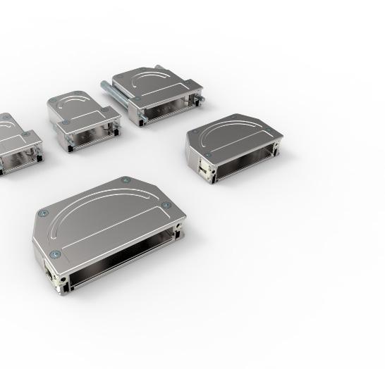

1 RAIL D-SUB BACKSHELLS FOR D-SUBMINIATURE CONNECTORS D-SUB BACK SHELLS /// DATA SHEET


2 RAIL D-SUB BACKSHELLS FOR D-SUBMINIATURE CONNECTORS TE Connectivity (TE) provide a comprehensive range of ruggedized metal backshells for D-Subminiature connectors that allow for a fast easy installation and assembly thanks to a practical construction with a minimum number of single parts. TE have many options available including two cable exit variants and a unique retrofitable quick-lock system for easy robust assembly in tight spaces. With a cable exit option of crimp inserts ensuring unparalleled 360 o EMI/EMC Shielding, the crimp insert also protects the conductors against damage during the crimping process. For quick and easy installation we also have a screw strain relief cable exit option which requires no special tooling. 2 Strain relief versions: Crimp for high vibration and extreme environmental conditions, torsion proof, 360 o EMI shielding Screw strain relief for easy cable preparation Self retaining assembly screws 225 o, 180 o and 135 o cable exit options High Quality die cast metal shell Large volume allows for dense packing. Several Turned steel screws options in M3 and UNC o EMI/EMC shielding for useage in EN50155 systems Full metal parts mean fire and smoke compliant M3 or UNC4-40 thread Cable Outlet Size 1 9/15p Size 2 15/26p Size 3 25/44p Size 4 37/62p Size 5 50/78p 180 o Cable Outlet 135 o Cable Outlet 225 o Cable Outlet D-SUB BACKSHELLS /// DATA SHEET


3 Screw Lock Options With multiple screw lock options our D-Sub backshells meet all requirements for D-Subminiature connectors. Knurled, 50mm length Allen Key, 24mm Thread M3 or UNC4-40 B A Knurled, 24mm A B C C A + C Ordering Information Locking Screw w/spring Washer Locking Screw Short Knurled Locking Screw Long Knurled Locking Screw Long Knurled and Locking Screw Short Knurled Cable Outlet Screw Length 20.7mm 24mm 50mm 24/50mm Positions Picture Thread 180 o 135 o 225 o UNC P/15P M UNC M UNC /26P M UNC M /44P UNC M /62P UNC M /78P UNC M


 Quick Lock pin options A Fixed female screwlock C Standard mounting hole D-Sub Female connector Length depending on panel")
 Panel (front mounted) B Threaded insert D Bracket mounting (2x Sub-D) Length depending on panel thickness Quick lock pins mounted in")
4 Quick Lock Hoods Our quick lock versions are an effective, time saving solution, with self retaining assembly screws and with its squeeze to release self locking system it also provides three cable exit options in just one single part. Self retaining assembly screws 225 o, 180 o and 135 o cable exit options in one part High Quality full metal Shell Large volume allows for dense packing. 360 o EMI/EMC shielding Squeeze to release, no screw locks needed, self locking during assembly. Easy retrofitting of existing systems with Quick Lock pins. (See Quick Lock pin options) Quick Lock pin options A Fixed female screwlock C Standard mounting hole D-Sub Female connector Length depending on panel thickness Quick lock pins mounted in existing M3 or UNC4-40 sockets Quick lock pins mounted in standard mounting holes using M3 nuts Panel (front or back mounted) Panel (front mounted) B Threaded insert D Bracket mounting (2x Sub-D) Length depending on panel thickness Quick lock pins mounted in threaded sockets on the backside of the connector 2x D-Sub connector used to connect two cables with eachother Panel (front mounted) Quick lock pins mounted in bracket using locking ring Panel D-SUB BACKSHELLS /// DATA SHEET
5 Ordering Information Quick Lock Versions Quick Lock Shells Shell Size Positions Picture Part Number Cable Outlet 225 o 180 o 135 o 1 9p/15p p/26p p/44p p/62p p/78p Quick Lock Pin Options Picture PN Thread Panel Thickness mm A M3 N/A UNC N/A UNC N/A UNC UNC B UNC UNC M3 N/A M M M M C M D N/A


 OD = 6.")

 + 0.2mm Thickness cable jacket = 6.5-4.4)/2 = 1.05mm Barrel ID = 5.5mm + 2x 1.05 + 0.2mm = 7.")
6 Cable Exit options Option 1: Crimped Strain relief Cable rotation can lead to breakage of the individual wires in the cable. This can lead to intermittent system errors which are typically very difficult to find. The Solution: Crimping the cable jacket Advantage: A well defined and proven method. The crimp insert protects the con-ductors against damage during the crimping process. Creating unparelleled EMI shielding all around the connector. Fits both Standard and Quick Lock hoods. Crimp barrel Crimp Flange Jacket Crimp Barrel Crimp Flange Cable Braid Conductors & Foil Cable braid connectors to Crimp insert providing 360 o EMI/EMC shielding How to select the correct crimp flange Step Description Example 1 Measure the outside cable diameter (3 times on different places at different angles) OD = 6.5mm 2 Strip the cable and remove the cable braiding 3 Measure the diameter of the inner cable bundle including the foil ID = 4.4mm 4 Select the crimp flange with a hole diameter next up to the cable bundle diameter PN = , ID = 4.5mm, OD = 5.5mm 5 Calculate the recommended barrel inner diameter with the following formula: Recommended Inner crimp barrel diameter = OD of crimp flange + 2x(thickness of the cable jacket) + 0.2mm Thickness cable jacket = )/2 = 1.05mm Barrel ID = 5.5mm + 2x mm = 7.8mm 6 Select the crimp barrel with the next size up 7 Order the correct crimp tool & crimp insert using the crimp barrel selection matrix PN = , ID = 8.0mm, OD = 9.0mm PN = & Prepare a cable sample and check if the pull out force meets your requirements. Contact TE Connectivity representative in case of any questions. D-SUB BACKSHELLS /// DATA SHEET


 Picture Part Number Barrel Inner diameter/cable diameter mm Barrel Outer diameter mm PN recommended crimp insert 1-2308350-1 5.0 6.")
7 Ordering Information Crimp Strain relief Picture Crimp flanges (Can be used with all shells) Size 1-4 QD shells 1-3 Std Shells P/N Size 5 QD shells or size 4-5 Std Shells P/N Inner diameter / cable diameter mm Outer diameter mm Recommended Tooling Cable Jacket stripping tool Crimp flange insert tool for small size flanges for large size flanges Crimp barrel (in combination wth crimp flanges) Picture Part Number Barrel Inner diameter/cable diameter mm Barrel Outer diameter mm PN recommended crimp insert Crimp tool Crimp Insert X X (see table for recommended crimp insert)


8 Cable Exit Options Option 2: Cable outlet with screws For quick and easy installation requiring no special tools TE s cable outlet with screws option suits those needing a fast and simple installation. With a two piece cable clamp to allow for effective strain relief this cable exit is fitted with ribs to prevent cable retention. Fits both Standard and Quick Lock hoods. Max compression to approx. 50% of the original volume Cable compressed by screws Ribs to prevent cable retention Ordering Information Standard shell Fits on shells Quick Lock shell Cable diameter Part Number 4-7mm Size 1-3 (small) Size mm mm mm mm Size 4-5 (Large) Size mm mm D-SUB BACKSHELLS /// DATA SHEET
9 NOTES While TE has made every reasonable effort to ensure the accuracy of the information in this brochure, TE does not guarantee that it is error-free, nor does TE make any other representation, warranty or guarantee that the information is accurate, correct, reliable or current. TE reserves the right to make any adjustments to the information contained herein at any time without notice. TE expressly disclaims all implied warranties regarding the information contained herein, including, but not limited to, any implied warranties of merchantability or fitness for a particular purpose. The dimensions in this catalog are for reference purposes only and are subject to change without notice. Specifications are subject to change without notice. Consult TE for the latest dimensions and design specifications.
10 LET S CONNECT We make it easy to connect with our experts and are ready to provide all the support you need. Just call your local support number or visit to chat with a Product Information Specialist. TECHNICAL SUPPORT te.com/support-center Australia France Korea Austria Germany Latvia Belgium Greece Lithuania Brazil Holland Luxembourg China Hungary Netherlands Czech Republic India New Zealand Denmark Ireland Norway Estonia Italy Poland Finland Japan Portugal te.com TE Connectivity, TE, TE Connectivity (logo), Every Connection Counts are trademarks. All other logos, products and/or company names referred to herein might be trademarks of their respective owners. The information given herein, including drawings, illustrations and schematics which are intended for illustration purposes only, is believed to be reliable. However, TE Connectivity makes no warranties as to its accuracy or completeness and disclaims any liability in connection with its use. TE Connectivity s obligations shall only be TE Connectivity Rail as set forth in TE Connectivity s Standard Terms and Conditions of Sale for this product and in no case will TE Connectivity be liable for any incidental, indirect or consequential damages arising out of the sale, resale, use or misuse of the product. Users of TE Connectivity products should make their own evaluation to determine the suitability of each such product for the specific application TE Connectivity Ltd. family of companies All Rights Reserved CC 1216 D-SUB BACKSHELLS /// DATASHEET
FINE PITCH BOARD-TO-BOARD CONNECTOR SERIES THE SMART WAY TO GO FOR RELIABILITY
 QUICK REFERENCE GUIDE FINE PITCH BOARD-TO-BOARD CONNECTOR SERIES THE SMART WAY TO GO FOR RELIABILITY FINE PITCH BOARD-TO-BOARD CONNECTOR SERIES When it comes to high-reliability in small spaces, TE delivers
FOSC-450D. Fiber Optic Splice Closure. 1 Introduction. Content. 5 Cable termination. 6 Fiber routing. 2 General. 7 Installation of the gel block
 FOSC-450D I N S T A L L A T I O N I N S T R U C T I O N Fiber Optic Splice Closure Content 1 Introduction 2 General 2.1 Kit content 2.2 Tools 2.3 Accessories 2.4 Capacity 3 Preparation of the closure 4
Medium Box for Cable Termination
 FIST-MB2-T I N S T A L L A T I O N I N S T R U C T I O N Medium Box for Cable Termination Contents 1 Introduction 1.1 Product description. 2 General 2.1 Tools 2.2 Kit contents 3 Installation and pre assembling
FOSC 450 C6 and D6 Closures
 FOSC 450 C6 and D6 Closures I N S T A L L A T I O N I N S T R U C T I O N Fiber Optic Splice Closure 1. General Product Information The FOSC 450 C6 and D6 fiber optic splice closures use compressed gel
FOSC-600 C and D I N S T A L L A T I O N I N S T R U C T I O N
 FOSC-600 C and D I N S T A L L A T I O N I N S T R U C T I O N In-line and butt version Cold applied re-usable fiber optic closure Contents 1 Introduction 1.1 Product description 1.2 Capacity 2 General
3M Distribution Box (DDB)
") 3M Distribution Box (DDB) Merged Copper and Fiber Pole/Post Mount Enclosure Installation Instructions November 2015 78-0015-2736-1-A 2 November 2015 78-0015-2736-1-A Contents 1.0 General 2.0 Enclosure
3M Distribution Box (DDB) Merged Copper and Fiber Pole/Post Mount Enclosure Installation Instructions November 2015 78-0015-2736-1-A 2 November 2015 78-0015-2736-1-A Contents 1.0 General 2.0 Enclosure
FIST-MB2-S. FIST Medium Box for Cable Splicing Only. 4 Cable installation. 1 Introduction. Contents. 2 General. 5. Fiber routing to individual trays
 FIST-MB2-S I N S T A L L A T I O N I N S T R U C T I O N FIST Medium Box for Cable Splicing Only Contents 1 Introduction 1.1 Product description 2 General 2.1 Tools 2.2 Kit contents 3 Installation and
3 SLiC Aerial Closure with Rubber End Seal
 3 Aerial Closure with Rubber End Seal Instructions 1.0 General 1.1 This instruction bulletin describes the assembly of the 3M Aerial Closure with external bonding hanger brackets. These closures are suitable
3 Closure preparation 3.1 Work-stand 3.2. Opening FIST-GCOG2-Dx Preparing drop cable with micro-tubes
 FIST-GCOG2-Dx24 I N S T A L L A T I O N I N S T R U C T I O N FTTH closure for micro-tubes and micro-cables Content 1 Introduction 2 Kit content 3 Closure preparation 3.1 Work-stand 3.2. Opening FIST-GCOG2-Dx24
3 Foam Sealed Closure 2" (50 mm) with Compound Compression
 with Compound Compression") 3 Foam Sealed Closure 2" (50 mm) with Compound Compression Instructions 1.0 General 1.1 The 3M Foam Sealed Closure is designed to be used in the construction and maintenance of buried and underground PIC
3 Foam Sealed Closure 2" (50 mm) with Compound Compression Instructions 1.0 General 1.1 The 3M Foam Sealed Closure is designed to be used in the construction and maintenance of buried and underground PIC
Cold Shrink Three-Conductor Splice Kit QS-III for use on Armor and Non-Armor Cables Instructions IEEE Std kv Class 250 kv BIL
 Cold Shrink Three-Conductor Splice Kit QS-III for use on Armor and Non-Armor Cables Instructions IEEE Std. 404 35 kv Class 250 kv BIL Kit Number 5798A-MT Cable Range Requirements Cable Insulation O.D.
3M Better Buried Closures
 3M Better Buried Closures Instructions March 2016 78-0015-2945-8-A Contents: 1.0 General... 3 2.0 Kit Contents... 3 3.0 Closure Selection Guide... 4 4.0 LHS End Cap Installation... 5 5.0 Cable Preparations...
Instruction Guide February 2017
 Instruction Guide February 2017 3M Instruction Guide: 3M TM Locator Plate 3443-81-XX, 3D-Printed Instructions for the assembly of 3M TM Ribbon Cable Wiremount Socket Assembly, 451 Series 1.0 General 1.1
3M SLiC 530/533/733-2 Port 0.61 Cable Entry Bracket 3M SLiC 530/533/733-2 Port-MSM 0.61 Cable Entry Bracket
 3M SLiC 530/533/733-2 Port 0.61 Cable Entry Bracket 3M SLiC 530/533/733-2 Port-MSM 0.61 Cable Entry Bracket For use with 3M SLiC Free-Breathing Fiber Optic Closures and Terminals Instructions November
PT9420 Cable Actuated Sensor Industrial ma 0..20mA
 PT9 Cable ctuated Sensor Industrial.. m 0..m bsolute Linear Position to 550 inches ( meters) luminum or Stainless Steel Enclosure Options VLS Option to Prevent Free-Release Damage IP68 / NEM 6 Hazardous
STEVAL-SPBT2ATV2. USB Dongle for the Bluetooth class 2 SPBT2532C2.AT module. Features. Description
 USB Dongle for the Bluetooth class 2 SPBT2532C2.AT module Data brief Features Bluetooth V2.1 board USB connection SMD antenna onboard RoHS compliant Description The demonstration board is a design tool
3M Better Buried Closure (with 3M Scotchlok Shield Bond Connector 4462-FN and 3M High Gel Re-enterable Encapsulant 8882)
") 3M Better Buried Closure (with 3M Scotchlok Shield Bond Connector 4462FN and 3M High Gel Reenterable Encapsulant 8882) Instructions April 2016 78813509979C Contents: 1.0 General... 1 2.0 Kit Contents...
3M Better Buried Closure (with 3M Scotchlok Shield Bond Connector 4462FN and 3M High Gel Reenterable Encapsulant 8882) Instructions April 2016 78813509979C Contents: 1.0 General... 1 2.0 Kit Contents...
2179-CD Series Fiber Optic Splice Closure. Installation Instructions
 2179-CD Series Fiber Optic Splice Closure Installation Instructions 1.0 Product Introduction The new 3M TM 2179-CD Series Fiber Optic Splice Closure can be used in buried, underground, aerial, and pedestal
Ordering Guide of the Fiber-Optic Splice Closure (FOSC-400)
") Page 1 of 11 Ordering Guide of the Fiber-Optic Splice Closure (FOSC-400) This document provides assistance with the selection of FOSC-400 closures. It includes the following sections: 1 Product description
Page 1 of 11 Ordering Guide of the Fiber-Optic Splice Closure (FOSC-400) This document provides assistance with the selection of FOSC-400 closures. It includes the following sections: 1 Product description
SLiC Fiber Aerial Closure System
 3 SLiC Fiber Aerial Closure System SLFC 533-SP SLFC 533-TS SLFC 733-SP Instructions May 2005 78-8135-4502-3-B N C H E S R A N G E M IL L IM E T E R S.4 10.6.8 A B C 15 20 I 1.0 Kit Contents Note: Examine
FIST-GCO2-OTIAN I N S T A L L A T I O N I N S T R U C T I O N
 FIST-GCO2-OTIAN I N S T A L L A T I O N I N S T R U C T I O N 24 Address Point Fibre distribution point (FDP) Installation guide for fibre DP Contents 1 Kit Contents 2 Accessories 3 MOBRA installation
3M Locator Plate N
 M Locator Plate 44-107N Instructions for the assembly of.100 x.100 preassembled socket connectors 1.0 General The M Locator Plate 44-107N is designed to aid in the assembly of the preassembled socket connector
3M Better Buried Compound Compression Closure System
 3M Better Buried Compound Compression Closure System Instructions March 2016 78-0015-2948-2-A Contents: 1.0 General...3 2.0 Kit Contents...3 3.0 Closure Selection Guide...4 4.0 LHS End Cap Installation...5
Instructions. Cable with Armor F CAUTION. October Rev A
 3M Single Conductor Accessory Breakout Kits (BOK's) for use with 3M Cable Accessories (Terminations, T-Bodies and Push-On Elbows) For Use With Single Conductor Accessories On Three-Core Conductor Cables
LCC (Little Coaxial Connector) Installation Instructions)
 Installation Instructions)") LCC (Little Coaxial Connector) Installation Instructions) Content Page INTRODUCTION...1 Revision History...1 Trademark Information...1 1 TOOLS...2 1.1 Connection Tool Kit...2 1.2 Tool Illustrations...2
LCC (Little Coaxial Connector) Installation Instructions) Content Page INTRODUCTION...1 Revision History...1 Trademark Information...1 1 TOOLS...2 1.1 Connection Tool Kit...2 1.2 Tool Illustrations...2
ASSEMBLY, INSTALLATION, AND REMOVAL OF CONTACTS AND MODULES
 ASSEMBLY, INSTALLATION, AND REMOVAL OF CONTACTS AND MODULES FOR 75 OHM AND 75 OHM HD COAXIAL CONTACTS AND MODULES Table of Contents SECTION 1 RECEIVER CONTACT ASSEMBLY INSTRUCTIONS SECTION 2 ITA CONTACT
LANmark PCB patch panel, 1HU INSTALLATION GUIDE. LANmark PCB patch panel, 1 HU
 LANmark PCB patch panel, 1HU INSTALLATION GUIDE LANmark PCB patch panel, 1 HU Document information Document reference Release September 2001 Published by Contact address BRO-009 LANmark PP 1HU 0701 Nexans
3M Fiber Optic Splice Closure 2178-XL & 2178-XL/FR
 3M Fiber Optic Splice Closure 2178-XL & 2178-XL/FR 3M Cable Addition Kit 2181-XL and 2181-XL/FR Instructions September 2017 78-8130-5055-2-M 2 September 2017 78-8130-5055-2-M 1.0 Kit Contents 2.0 General...
3M Fiber Optic Splice Closure 2178-XL & 2178-XL/FR 3M Cable Addition Kit 2181-XL and 2181-XL/FR
 3M Fiber Optic Splice Closure 2178-XL & 2178-XL/FR 3M Cable Addition Kit 2181-XL and 2181-XL/FR Instructions July 2010 3 1.0 Contents 1.0 General...3 2.0 Kit Contents...3 3.0 Cable Preparation...4 4.0
Installation instructions Roxtec RM BG systems
 Safety information Roxtec recommends that all installations are performed without facility operation. Follow national regulations and installation codes. ny action affecting the routed service should be
Multi-channel LED driver with integrated boost controller for medium, large LCD panel backlight based on LED7708 and STM32F103C6T6A
 Multi-channel LED driver with integrated boost controller for medium, large LCD panel backlight based on LED7708 and STM32F103C6T6A Features Data brief Wide DC input voltage: 10 V to 28 V Integrated boost
3M Cold Shrink Foldback Splice Jacket Kit
 3M Cold Shrink Foldback Splice Jacket Kit SJ-FB Instructions! CAUTION Working around energized systems may cause serious injury or death. Installation should be performed by personnel familiar with good
6000 Series Patch Panel Terminating Instructions
 6000 Series Patch Panel Terminating Instructions INTRODUCTION The 6000 Series patch panels include a unique feature not found on any other patch panel. This feature allows you to angle each of the four
Multi-Media Installation Guide
 Multi-Media Installation Guide Coaxial Page 2 Data Plug Page 7 Data Jack Page 10 Telephone Page 13 Splicing Page 15 Cable Types Cable Types Two basic types of cable are used in multimedia installations.
National Wire and Cable and National Cable Molding Headquarters Los Angeles California
 National Wire and Cable and National Cable Molding Headquarters Los Angeles California CAPABILITIES Medical Business Machines Communications Equipment Computer Equipment Audio Systems General Instrumentation
HARTING Ethernet cabling cables and connectors, 4 wire
 Industrial Cat. 5e Standard cable, 4-wire Type A for permanent installation or to build-up PROFINET system cables PVC X 8 wire X Cat. 5e X Cat. 6 Cat. 6 A Cat. 7 Cable structure Core structure Wire insulation
3M Fiber Optic Splice Closure 2178-XSB/XSB-FR & 2178-XLB/XLB-FR 3M Cable Addition Kit 2181-XB/XB-FR
 3M Fiber Optic Splice Closure 2178-XSB/XSB-FR & 2178-XLB/XLB-FR 3M Cable Addition Kit 2181-XB/XB-FR Instructions July 2010 78-8135-0094-5-K 3 1.0 General 1.1 3M Fiber Optic Splice Closure 2178-XSB The
3M Cold Shrink QS-III Silicone Rubber Splice Kit 5488A-TOW/WOT
 3M Cold Shrink QS-III Silicone Rubber Splice Kit 5488A-TOW/WOT For Tape Over Wire (TOW) and Wire-Over-Tape (WOT) Shielded Cable For 250 2000 kcmil cable with 650-mil primary insulation thickness Instructions
Crimplok. Connectors. 3M Crimplok ST* Connector Multimode 1. 3M Crimplok SC Connector Single-mode 2
 3 Crimplok Connectors Quick, easy installation and superior performance To successfully design, install or operate today s fiber optic networks, you need components that offer speed and reliability from
BT Series of Battery-Hydraulic Hand Tool Kits
 BT Series of Battery-Hydraulic Hand Tool Kits Fast Facts More than a ton of power in your hand. (BT 3500) Highly Portable Lightweight Ergonomic Compatible with SDE dies and numerous heads 9 different heads/adapters
3M Mini D Ribbon (MDR) Cable Assembly
 Cable Assembly") 3M Mini D Ribbon (MDR) Cable Assembly.050 Digital Camera Extension Cable 26 position 1WL26-TZ3B-XXX-03C Mates to popular 3M MDR 26 position receptacle on one end, and to another MDR 26 position cable assembly
3M Mini D Ribbon (MDR) Cable Assembly.050 Digital Camera Extension Cable 26 position 1WL26-TZ3B-XXX-03C Mates to popular 3M MDR 26 position receptacle on one end, and to another MDR 26 position cable assembly
Installation instructions Roxtec RM BG B systems
 Safety information Roxtec recommends that all installations are performed without facility operation. Follow national regulations and installation codes. ny action affecting the routed service should be
ROBOT-M24LR16E-A. Evaluation board for the M24LR16E-R dual interface EEPROM. Features. Description
 Features Evaluation board for the M24LR16E-R dual interface EEPROM 20 mm x 40 mm 13.56 MHz inductive antenna etched on PCB M24LR16E-R dual interface EEPROM I²C connector Energy harvesting output (V OUT
Interconnections. General characteristics. Plug
 NEW Interconnections Sockets Sockets Plug General characteristics 0R and 1R series connectors provide the following main features: Security of the Push-Pull LEMO self-latching system Housing of composite
EVALPM8803-FWD. EVALPM8803-FWD: IEEE802.3at compliant demonstration kit with synchronous active clamp forward PoE converter. Features.
 : IEEE802.3at compliant demonstration kit with synchronous active clamp forward PoE converter Features EEE 802.3at compliant Support for Gigabit Ethernet Data pass-through for the ethernet data Works with
3M Motor Lead Inline Splice 5331, 5332, 5333 & 5334
 3M Motor Lead Inline Splice 5331, 5332, 5333 & 5334 for 5/8 kv Non-Shielded and Shielded Cables (Ribbon, Wire and UniShield Cables) Instructions Cable Size Range: Feeder: #8 AWG 500 kcmil Motor Lead: #10
STEVAL-ILH004V1. 70 W electronic ballast for metal halide lamp (HID) based on the L6382D5 and ST7FLITE49K2. Features. Description
 based on the L6382D5 and ST7FLITE49K2. Features. Description") 70 W electronic ballast for metal halide lamp (HID) based on the L6382D5 and ST7FLITE49K2 Data brief Features Minimum mains voltage (rms value): 85 V Maximum mains voltage (rms value) : 265 V Minimum mains
70 W electronic ballast for metal halide lamp (HID) based on the L6382D5 and ST7FLITE49K2 Data brief Features Minimum mains voltage (rms value): 85 V Maximum mains voltage (rms value) : 265 V Minimum mains
Sections 1. Application Equipment 2. Cable Preparation 3. Assembly 4. Termination Procedure 5. Inspection 6. Repair 7.
 Page 1 of 6 Coaxial SolderSleeve Termination with Pre-Installed Wires or PCB Termination Body, B-044, B-043, B-041, B-040, B-020, B-021, B-046, D-148 Series Cable Type Typical RG Cable # -A- RG 178 RG
High Density Block BRCP. HD BRCP- 128/192/256 pair. Installation Instructions
 High Density Block BRCP HD BRCP- 128/192/256 pair Installation Instructions Product Introduction The BRCP block is the latest generation of MDF terminal blocks developed by 3M, specifically designed for
Installation instructions Roxtec RM ES systems
 Safety information Roxtec recommends that all installations are performed without facility operation. Follow national regulations and installation codes. ny action affecting the routed service should be
CANNON STANDARD page 1 of 18. Cm5 MOTOR CONNECTOR
 CANNON STANDARD page 1 of 18 1 General Information... 2 1.1 Scope... 2 2 Ordering Code... 3 2.1 Housing / Motor Side... 3 2.2 Cable Side... 3 3 Explosion Drawing... 3.1 Explosion Complete Assembly... 3.2
Speed sensor MiniCoder GEL 2471
 Speed sensor MiniCoder GEL 2471 for electrically conducting toothed-wheels Technical information version 10.02 The MiniCoder family from Lenord + Bauer offers spacesaving solutions for the contactless
Installation Instructions. What This Option Provides
 Installation Instructions IN Bulletin 1336 PLUS, 1336 IMPACT, and 1336 FORCE TM NEMA Type 4/12 Gasket Kit Installation & Drive Mounting (Catalog Number 1336 RF2 1336S RF3 1336 RF4 1336 RF5 1336 RF6 1336
3M Scotchcast Reenterable Signal and Control Cable Splicing Kits 78-R Series
 3M Scotchcast Reenterable Signal and Control Cable Splicing Kits 78-R Series Instructions Voltage Rating: 1000 V, Temperature Rating: 90 C Kit Contents 78-R1 78-R2 78-R3 78-R4 78-R5 Sleeve Set 1 1 1 1
2178-L/S Series Fiber Optic Splice Case with Gasket
 2178-L/S Series Fiber Optic Splice Case with Gasket Instructions for: 2178-S Splice Case 2178-LS Splice Case 2178-LL Splice Case 2181-LS Cable Addition Kit May 1997 34-7041-9949-5-A 1 Table of Contents
Installation Instructions
 TECP-30-260 Issue 2 July 2016 Installation Instructions OWB-S OWB-S Small Wall-mounted Box CONTENTS 1. Introduction 2. Kit content 3. Installation Instruction 3.1. Box installation 3.2. Conduit installation
Quick Term III. 3M Cold Shrink 3 Core Indoor Termination. 3.3 kv mm 2
 Quick Term III 3M Cold Shrink 3 Core Indoor Termination Instruction Sheet All dimensions shown are mm unless otherwise stated Kit Contents 3 QT-III Termination Assembly 1 Cold Shrink Breakout Boot 3 Phase
Installation instructions Cable transit device Roxtec RS ES Ex
 General information Installation and maintenance: For European member countries of GENELEC, shall standard EN 60079-14 and EN 60079-17 be considered. For countries members of IECEx shall standard IEC 60079-14
2178 Fiber Optic Splice Case and 2181 Cable Addition Kit
 2178 Fiber Optic Splice Case and 2181 Cable Addition Kit Instructions January 1994 Issue 1, 34-7029-6387-6 1 2 Contents: 1.0 General... 4 2.0 Specifications... 4 3.0 Kit Contents... 5 SECTION 1: 2178 Splice
3M Cold Shrink QS4 Integrated Splice Kit QS4-35TS
 3M Cold Shrink QS4 Integrated Splice Kit QS4-35TS-350-1000 for Tape Shield, Wire Shield, UniShield, and Longitudinally Corrugated (LC) Cable Instructions IEEE Std. 404 35 kv Class 250 kv BIL F CAUTION
Introducing Ultra Short LC : Fiber Optic Cable Assemblies
 Introducing Ultra Short LC connector based, high quality single mode and multi mode fiber optic cable assemblies have been designed to meet the highest and most demanding Industry standards. The newly
Ultra-Grip Crimp Connector Hand Tool Kit for Coaxial Cable and Powerpole Connectors
 Ultra-Grip Crimp Connector Hand Tool Kit for Coaxial Cable and Powerpole Connectors DXE-UT-KIT-CRIMP DXE-UT-KIT-CRIMP-INS-Revision 2b DX Engineering 2014 1200 Southeast Ave - Tallmadge, OH 44278 USA Phone:
STEVAL-IHM043V1. 6-step BLDC sensorless driver board based on the STM32F051 and L6234. Features. Description
 6-step BLDC sensorless driver board based on the STM32F051 and L6234 Features Input voltage range: 7 to 42 V dc Output current: 2 A (5 A peak) Can operate up to 100% duty cycle RoHS compliant Description
STEVAL-ICB004V1. Advanced resistive touchscreen controller demonstration board based on the STMPE811. Features. Description
 Advanced resistive touchscreen controller demonstration board based on the STMPE811 Data brief Features Four-wire resistive touch-sensing demonstration GUI Configurable touch-sensing parameters STMPE811
Installation instructions Ex frames
 General information Installation and maintenance: For European member countries of GENELEC shall standard EN 60079-14 and EN 60079-17 be considered. For countries members of IECEx shall standard IEC 60079-14
STEVAL-CCH002V2. HDMI and video switches demonstration board. Features. Description
 HDMI and video switches demonstration board Data brief Features 16-character x 2-line alphanumeric backlit LCD VGA input and output connectors S-video input and output connectors Y Pb Pr input and output
F CAUTION. Jacketed Concentric Neutral (JCN) Cable. Concentric Neutral (CN) Cable. IEEE Std. No. 48 Class 1 Termination 15 kv Class 110 kv BIL
 Cable. Concentric Neutral (CN) Cable. IEEE Std. No. 48 Class 1 Termination 15 kv Class 110 kv BIL") 3M Cold Shrink QT-III Silicone Rubber Skirted Termination Kit With High-K Stress Relief 7642-S-2 For Jacketed Concentric Neutral (JCN) and Concentric Neutral (CN) Cable Instructions IEEE Std. No. 48 Class
3M Cold Shrink QT-III Silicone Rubber Skirted Termination Kit With High-K Stress Relief 7642-S-2 For Jacketed Concentric Neutral (JCN) and Concentric Neutral (CN) Cable Instructions IEEE Std. No. 48 Class
Obsolete Product(s) - Obsolete Product(s)
 - Obsolete Product(s)") Features Camera with ZigBee connectivity based on the STM32 STM32-based camera with ZigBee connectivity Includes microsd card and ZigBee module Works with monitoring unit (order code STEVAL-CCM003V1) Camera
Features Camera with ZigBee connectivity based on the STM32 STM32-based camera with ZigBee connectivity Includes microsd card and ZigBee module Works with monitoring unit (order code STEVAL-CCM003V1) Camera
Obsolete Product(s) - Obsolete Product(s)
 - Obsolete Product(s)") Adapter board (daughter board for the STM3210C_EVAL) for a thermal printer based on the L293DD Data brief Features This application is designed for a connectivity line demonstration board. The thermal
Adapter board (daughter board for the STM3210C_EVAL) for a thermal printer based on the L293DD Data brief Features This application is designed for a connectivity line demonstration board. The thermal
STEVAL-ISB008V1. Standalone USB Li-Ion battery charger demonstration board based on the STw4102 and STM32F103C6. Features.
 Features Standalone USB Li-Ion battery charger demonstration board based on the STw4102 and STM32F103C6 Data brief The STw4102 Li-Ion battery charger IC: supports battery charging by USB or external DC
TE Connectivity DEUTSCH DL Series MIL-DTL Series III Connectors
 Applications Features TE Connectivity DEUTSCH DL Series MIL-DTL-83723 Series III Connectors High-performance military aircraft Commercial aircraft Communications equipment Armored personnel carriers &
3M Cold Shrink QS4 Integrated Splice Kit QS4-15JCN
 3M Cold Shrink QS4 Integrated Splice Kit QS4-15JCN-500-1000 for Jacketed Concentric Neutral (JCN) and Flat Strap Neutral Cable Instructions IEEE Std. 404 15 kv Class 150 kv BIL F CAUTION Working around
3M Cold Shrink Splice Kit QS-III 5416A
 3M Cold Shrink Splice Kit QS-III 5416A for Jacketed Concentric Neutral (JCN) and Concentric Neutral Cable Instructions IEEE Std. 404 15 kv Class 150 kv BIL CAUTION Working around energized systems may
STEVAL-IKR001V7D. Sub Ghz transceiver daughterboard with power amplifier based on the SPIRIT1. Features. Description
 Sub Ghz transceiver daughterboard with power amplifier based on the SPIRIT1 Data brief Features SPIRIT1 low power sub GHz transceiver in a standalone RF module tuned for 169 MHz band with external power
Ultra-Grip 2 Crimp Connector Hand Tool Kit for Coaxial Cable Connectors, Powerpole Connectors, Insulated and Non-Insulated Crimp Terminals
 Ultra-Grip 2 Crimp Connector Hand Tool Kit for Coaxial Cable Connectors, Powerpole Connectors, Insulated and Non-Insulated Crimp Terminals DXE-UT-KIT-CRMP2 DXE-UT-KIT-CRMP-INS-Revision 0a DX Engineering
Order code Package Connection. SPDC400FC12M0.60 Open frame Comb. October 2007 Rev 1 1/9
 DC-DC step down power supply Preliminary Data Features Module DC-DC step down single output Wide range input voltage 100 370 V dc Output power 8W max Output voltage precision 5% Output short circuit protection
HSK Mine and Portable Cable Splice
 8096-4-HSK Mine and Portable Cable Splice Instructions 5 and 8 kv rated cables; Type SHD-GC Size 2/0 4/0 (connector max. length 2 1/2") 8096-4-HSK Mine and Portable Cable Splice 78-8119-6296-4-A 1 1.0
NEW. Cable/Pipe sizes. InsertStrip. MainBlock
 W E N HandiBlock Newly developed insert block that provides greater flexibility, simple and safe installation. Tested and approved by leading classification societies and patented world wide. NEW Greater
3M Cold Shrink Splice Kit QS-III 5515A
 3M Cold Shrink Splice Kit QS-III 5515A for UniShield, Wire Shielded, Longitudinally Corrugated (LC), and Tape Shielded (Ribbon Shielded) Cable or Transitions to Concentric Neutral (CN)/Jacketed Concentric
Amphenol. Amphenol-Tuchel Electronics GmbH. C 112 Series M12 - Connectors
 Amphenol Amphenol-Tuchel Electronics GmbH C 112 Series M12 - Connectors We connect con The company Amphenol-Tuchel Electronics is a worldwide leader in electrical connectors and contacting devices. Our
Linear Array with Intensity Adjustment
 Datasheet High-Power Lighting with Intensity Adjustment for use with Vision Systems For complete technical information about this product, including dimensions, accessories, and specifications, see www.bannerengineering.com/lineararraylights.
PT8420 Cable Actuated Sensor Industrial ma 0..20mA
 PT8 Cable ctuated Sensor Industrial.. m..m bsolute Linear Position to 6 inches (5 mm) luminum or Stainless Steel Enclosure Options VLS Option to Prevent Free-Release Damage IP68 / NEM 6 Hazardous rea Certification
STEVAL-ILH005V W electronic ballast for HID lamps based on the L6562A and ST7LITE39F2. Features. Description
 150 W electronic ballast for HID lamps based on the L6562A and ST7LITE39F2 Data brief Features Minimum mains voltage: V ac(min) = 185 V Maximum mains voltage: V ac(min) = 265 V Minimum mains frequency:
K & B Flame Retardant Building Riser Closures
 K & B Flame Retardant Building Riser Closures September 1995 Issue 1, 34-7016-7030-8 1. General 1.1 3M Brand K&B Building Riser Closures are designed for use in building riser closets and may be positioned
Automatic Connector MHV Connectors MHV Introduction MHV series connectors Contents Polarized mating interfaces Anti-Rock mating interfaces
 Automatic s 2004 Automatic. All rights reserved. pdf 1.0 3-18-04 Contents Specifications........................... 2 Straight Cable Plugs...................... 3 Right Angle Cable Plugs...................
Installation instructions Roxtec RM ES
 Installation instructions Roxtec RM ES Environmental side Environmental side Pipe Cable screen/armor Layers Layers Cable sheath Vertical screen Plastic film Conductive tape Integrated environmental sealing
18mm ECAM Cable Entry Port
 18mm ECAM Cable Entry Port Instructions October 2006 1.0 Introduction The 3M 18mm ECAM (External Cable Assembly Module) Cable Entry Port Kit is designed to accept fiber optic cables with external diameters
In-Wall Control Mount for ipod Touch
 In-Wall Control Mount for ipod Touch INTRODUCTION The Mirage KP-iOS is an in-wall system that allows ipod touch (4th generation) to become a semi-permanent fixture in your wall. The system allows you to
EXPlora. Introduction
 Introduction EXPlora The EXPlora range is most suited to manufacturers of ancillary electrical equipment such as motors, pumps, lighting equipment, process and control gear for use in factories and plant
Obsolete Product(s) - Obsolete Product(s)
 - Obsolete Product(s)") DC-DC step down power supply Features Module DC-DC step down single output Wide range input voltage: 100 370 V dc Output power: 4.0 W typ. Output voltage precision 5% Output short-circuit protection No
DC-DC step down power supply Features Module DC-DC step down single output Wide range input voltage: 100 370 V dc Output power: 4.0 W typ. Output voltage precision 5% Output short-circuit protection No
STEVAL-ILL029V1. Front panel demonstration board based on the STLED325 and STM8S. Features. Description
 Front panel demonstration board based on the STLED325 and STM8S Data brief Features 4-digit, 7-segment (with decimal point) LED display 8 discrete LEDs 8 front panel keys for control of channel, brightness
3M 8900 Single-mode SC Crimplok Connector
 3M 8900 Single-mode SC Crimplok Connector Technical Report June 1999 80-6110-1441-8 1 1.0 Product Description & Requirements The 3M SC Single-mode Crimplok Connector is designed to provide the customer
OWNER'S MANUAL SIGNAL COMMANDER
 OWNER'S MANUAL SIGNAL COMMANDER THIS MANUAL CONTAINS INSTRUCTIONS FOR: LPDA 200 - INSTALLATION - OPERATION - TROUBLESHOOTING - EXPLODED PARTS DRAWING - WARRANTY AntennaTek, Inc. 425 S. Bowen, #4 Longmont,
Installation instructions Roxtec CM PE systems
 Safety information Roxtec recommends that all installations are performed without facility operation. Follow national regulations and installation codes. ny action affecting the routed service should be
CR-R880-BL: Indoor/Outdoor Proximity Reader with 10cm (4in) read range
 read range") CR-R880-BL: Indoor/Outdoor Proximity Reader with 10cm (4in) read range Installation Manual Table of Contents Basic Operation...2 CR-R880-BL Block Diagram...2 Technical Specifications...3 Features...4
CR-R880-BL: Indoor/Outdoor Proximity Reader with 10cm (4in) read range Installation Manual Table of Contents Basic Operation...2 CR-R880-BL Block Diagram...2 Technical Specifications...3 Features...4
TN0885 Technical note
 TN0885 Technical note New I 2 PAKFP (TO-281) package, practical approach for compact and slim product design needs Introduction STMicroelectronics has introduced a new package family, I 2 PAKFP, which
STEVAL-TDR007V1. 3 stage RF power amplifier demonstration board using: PD57002-E, PD57018-E, 2 x PD57060-E. Features. Description
 3 stage RF power amplifier demonstration board using: PD57002-E, PD57018-E, 2 x PD57060-E Features N-channel enhancement-mode lateral MOSFETs Excellent thermal stability Frequency: 1030 MHz Supply voltage:
3M No Polish Jacketed SC/APC Connector
 Communication Markets Division 3M No Polish Jacketed SC/APC Connector For use with 1.6 to 3.0 mm Jacketed Cable 3M No Polish SC/APC Connector enables fast, on-site termination of 1.6 mm to 3.0 mm jacketed
3M Cold Shrink Splice Kit QS-III 5514A
 3M Cold Shrink Splice Kit QS-III 5514A for UniShield, Wire Shielded, Longitudinally Corrugated (LC), and Tape Shielded (Ribbon Shielded) Cable or Transitions to Concentric Neutral (CN)/Jacketed Concentric
Obsolete Product(s) - Obsolete Product(s)
 - Obsolete Product(s)") L6563 80W High performancetm PFC with active tracking boost function General description Data Brief L6563 is a current-mode PFC controller operating in Transition Mode (TM). Based on the core of a standard
L6563 80W High performancetm PFC with active tracking boost function General description Data Brief L6563 is a current-mode PFC controller operating in Transition Mode (TM). Based on the core of a standard