The Road to Single Mode: Direction for choosing, installing and testing single mode fiber
|
|
|
- Margery Andrews
- 5 years ago
- Views:
Transcription
1 The Road to Single Mode: Direction for choosing, installing and testing single mode fiber Adrian Young Leviton Network Solutions Jim Davis Fluke Networks
2 Adrian Young, Sr. Applications Engineer Leviton Networks Solutions Single Mode Applications/Design
3 Traditional thoughts on single mode More challenging to keep clean Less generations of fiber to deal with Transceivers are more expensive Applications are duplex, no need for MPOs to achieve higher speeds Greater distance with single mode transceivers Greater insertion loss allowed ( 6.7 db) compared to multimode Reflectance (return loss/back reflection) concerns Uses high power lasers safety concerns May have to use an attenuator on shorter links
4 Multimode vs. single mode Multimode is easier to deal with Dust in an office 2.5 to 10 µm Human hair 100 µm Core It is a great deal easier to block all the light in a single mode end face Multimode OM2, OM3, OM4, OM5 Single mode OS1a, OS2
5 Less generations of fiber to deal with Multimode Cable Type 100GBASE SR4 Single Mode Cable Type 100GBASE DR OM1 Not supported OS1a 500 m OM2 OM3 OM4 Not supported 70 m 100 m OM5 100 m OS2 500 m If you installed OS1a back in 1999 or OS2 today in 2018, the distance reach is the same for 100GBASE DR The connectors may need replacing, but no pulling new cable Decision to install multimode driven by transceiver cost
6 Transceivers are more expensive Single mode transceivers have certainly come down in cost There was a time when you could say 7.5 x cost of multimode Large (hyper scale) data centers driving the demand for low cost single mode transceivers have changed the enterprise and data center markets 100GBASE SR4 (multimode) 100GBASE PSM4 (single mode)
 10GBASE LR 10,000 10GBASE LX4 10,000 10GBASE ER 40,000 10GBASE ZR 80,000 40 Gb/s Distance (m) 40GBASE LRL4")
 200GBASE FR4 2,000 200GBASE LR4 10,000 400 Gb/s Distance (m) 400GBASE FR8 2,000")
7 Single mode options to 400 Gb/s (duplex) 1 Gb/s Distance (m) 1000BASE LX 5, BASE LX10 10, BASE EX 40, BASE ZX 70, Gb/s Distance (m) 10GBASE LR 10,000 10GBASE LX4 10,000 10GBASE ER 40,000 10GBASE ZR 80, Gb/s Distance (m) 40GBASE LRL4 1,000 40GBASE FR 2,000 40GBASE LR4 10,000 40GBASE ER4 40, Gb/s Distance (m) 100GBASE DR GBASE CWDM4 2, GBASE LR4 10, GBASE ER4 40, Gb/s Distance (m) 200GBASE FR4 2, GBASE LR4 10, Gb/s Distance (m) 400GBASE FR8 2, GBASE LR8 10,000
 100GBASE PSM4 500 200 Gb/s")

8 Single mode options to 400 Gb/s (Parallel) 40 Gb/s Distance (m) 40GBASE PLR4 1, Gb/s Distance (m) 100GBASE PSM Gb/s Distance (m) 200GBASE DR Gb/s Distance (m) 400GBASE DR4 500 Transceiver cost reduced These options allow breakout Increases port density =
 ½ RU ½ RU 25")
9 100GBASE PSM4 breakout 8 Fiber MTP 24 Fiber MTP 24 Fiber MTP HDX Cassette 72 Fiber HDX2 Cassette TX1 TX2 TX3 TX4 RX4 RX3 RX2 RX1 LC Duplex Fiber (LC) ½ RU ½ RU 25 Gb/s


10 100GBASE PSM4 by the numbers 0.75 db nm HDX Cassette 500 m (1640 ft.) 72 Fiber HDX2 Cassette = Increase your density further GBASE PSM4 3.3 db Design = 1.45 db 0.50 db

11 Greater insertion loss allowed No longer a true statement With cheaper transceivers 100GBASE ER4 comes a reduced allowance 100GBASE LR4 for insertion loss 100GBASE CWDM4 Designers need to be aware of 100GBASE PSM4 the reduced loss budget for the 100GBASE DR newer transceivers targeted at data centers If your design has multiple connections, you can run into trouble 100 Gb/s Ethernet Channel Loss 15.0 db 6.3 db 5.0 db 3.3 db 3.0 db

 Angled Physical Contact (APC) Putting an 8 angle on the end face results in the mode of light")
12 Return loss (reflectance) What is return loss? It s light reflected back into the transceiver Caused by a change in refractive index (glass air glass) At higher data rates, errors are generated if too much light is received back Physical Contact (PC) Angled Physical Contact (APC) Putting an 8 angle on the end face results in the mode of light being forced back into the cladding rather than the transceiver
13 Return loss (reflectance) concerns ANSI/TIA D calls out connector return loss IEEE (Ethernet) calls out reflectance for connections Measured using Optical Time Domain Reflectometers (OTDRs) Call out reflective events as reflectance Return loss or reflectance? Practically speaking, they re the same thing Return loss is a positive number (45 db) Reflectance is a negative number ( 45 db)
14 Sensitive to reflectance (return loss) 100GBASE DR Maximum channel insertion loss (db) Number of connections where the reflectance is between 35 and 45 db Number of connections where the reflectance is between 45 and 55 db Let s take an example link containing four LC/MTP cassettes Single mode MTPs are APC, so there will be four of those (typically > 55 db) The four LCs are factory polished (typically >= 50 db) We have no connections between 35 db and 45 db So our allowable loss will be 3.0 db 3.0
15 Sensitive to reflectance (return loss) 100GBASE DR Maximum channel insertion loss (db) Number of connections where the reflectance is between 35 and 45 db Let s take another example of a link containing four LC/MTP cassettes Single mode MTPs are APC, so there will be four of those (typically > 55 db) The four LCs are factory polished (typically >= 50 db) Future performance could be less than 45 db So our allowable loss would be 2.7 db Number of connections where the reflectance is between 45 and 55 db

16 Uses higher powered lasers Long haul versions only Class 1M lasers for 100GBASE DR A Class 1M laser is safe for all conditions of use except when passed through magnifying optics such as microscopes and telescopes. 100GBASE PSM4 100GBASE CWDM4 LASER RADIATION DO NOT VIEW DIRECTLY WITH OPTICAL INSTRUMENTS CLASS 1M LASER PRODUCT Fiber Scope (Built in filter)

 lasers are")

17 Attenuators If the link is too short, the transmitted light could saturate the receiver This is typically an issue associated with high power lasers only The sort of lasers you find in outside plant such as cable tv If the link is short, the designer will add an attenuator Alternatively, a quick fix is to put a bend in the fiber and tape it in the cabinet/tray In the Data Center, low power Fabry Pérot (FP) lasers are used These lasers have a nominal output of 3 dbm Distributed Feedback Lasers can be found in CWDM4 transceivers These laser have a nominal output of 2.5 dbm IEEE typically specifies a minimum distance of 2.0 m (6.6 ft.)
18 100GBASE PSM4 in a switch to switch environment Your Design
19 8, 12, or 24 fiber MPO? These applications use 8 fibers: 40GBASE PLR4 200GBASE DR4 100GBASE PSM4 400GBASE DR4 TX1 TX2 TX3 TX4 RX4 RX3 RX2 RX1 There is no such thing as an 8 fiber MPO The transceiver vendors use a 12 fiber MPO The 4 fibers in the middle are left unused Can lead to an inefficient cabling system

20 8 Fiber MTP 100GBASE PSM4 efficient design 24 Fiber MTP 24 Fiber MTP HDX Cassette HDX Cassette 144 Fiber TX1 TX2 TX3 TX4 RX4 RX3 RX2 RX1 8 Fiber MTP ½ RU ½ RU

 144 Fiber 0.")


21 100GBASE PSM4 by the Numbers 0.75 db nm 500 m (1640 ft.) 144 Fiber = GBASE PSM4 3.3 db Design = 1.7 db 0.75 db
22 Take aways Cost of data center single mode transceivers are being driven down PSM4 over MPO links allows breakout to LCs for increased density Conversion cassettes provide an efficient design Single mode distances low as 500 m, transceiver dependent Loss budgets on single mode have been reduced Return loss (reflectance) can impact your loss budget further
23 Jim Davis, Regional Marketing Engineer Fluke Networks Single Mode Testing
24 Inspection and Cleaning Agenda Loss Testing Set reference find the difference Options for MPO cables Tester with MPO Port Three jumper reference How to Read Test Results
25 Repeat as needed Inspection and Cleaning


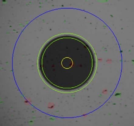
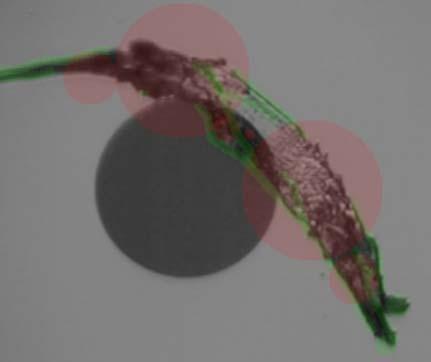
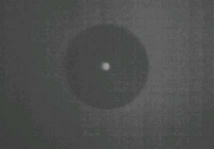
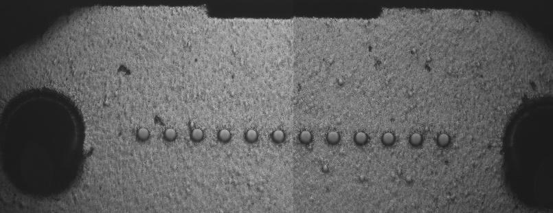
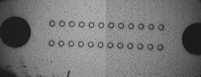
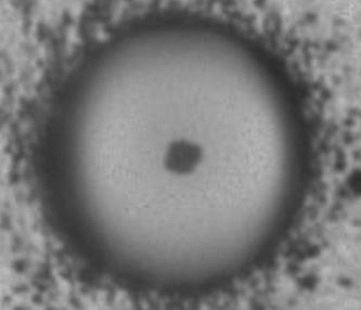
26 Inspect, Clean, Repeat Video Microscope Brand new out of bag After Cleaning 26
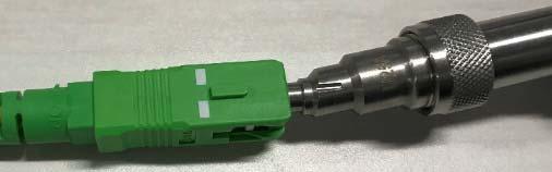
27 Inspecting APC Connectors Compensate for Angle Same cleaning equipment new camera tips PC/UPC APC


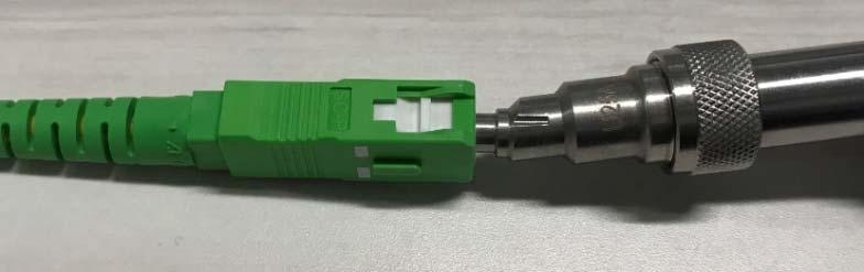
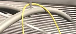
28 APC Tips Have a Slight Bend These are SC

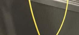
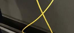
29 APC Connectors May Need a Twist to Show Up

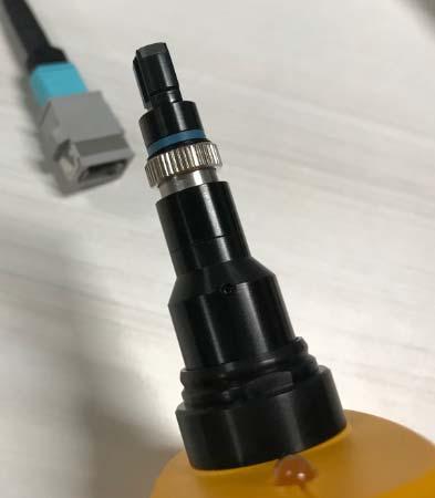
30 Single mode MPO connectors also need an adapter
31 Loss Testing


 All connections")
32 First Set a Reference > Then Find the Difference Optical Loss Measured Direct connection (No bulkhead adapter!) All connections are included in the loss measurement


33 Tier 1 (OLTS) Certification Test Reference Cords (TRCs) are a requirement in ANSI/TIA and ISO/IEC Patch cords from a distributor are specified with a loss of up to 0.50 db Test Reference Cords per ANSI/TIA and ISO/IEC Multimode Loss 0.10 db Single mode Loss 0.20 db


34 Tech Tip Before setting a reference, allow cords to relax Helps remove the bend from the cords
35 For Most Accurate Measurement, Use 1 Jumper Reference (This Provides the Least Uncertainty) Power meter requires a variable adapter to match port on fiber patch panel Check your manufacturers specification for valid reference values Reference Grade Test Reference Cords (TRC)


36 Then Remove Cords from Power Meter There is no physical contact/ alignment at the power meter APC Connector can also be used
37 TRC Verification Connect the Known Good leg using a single mode adapter and measure the loss Loss should be 0.25 db Save this test Known Good Cord Known Good Cord ISO/IEC db for Multimode 0.2 db for Single mode
38 Insert the Link to be Tested Pass or Fail results depend on the limit selected Test at two wavelengths 1310 nm and 1550 nm
39 Bend Detection and Future Proofing Wavelengths are bound If 1310 nm and 1550 nm pass, the others wavelengths will pass Attenuation (db/km) Wavelength (nm)


40 A Quick Study of Testing at Two Wavelengths A Single Fiber Link More Loss at 1310 than 1550 A Single Fiber Link with a Bend More Loss at 1550 than 1310

41 OTDR Trace Shows Location of Bend But not at 1310 nm 1310 nm


42 OTDR Trace Shows Location of Bend But not at 1310 nm 1550 nm
43 MPO/MTP Testing with OLTS
44 Two Options for Testing MPO to MPO Cables Traditional duplex field tester Dedicated MPO field tester
45 MPO/MTP Testing with OLTS 3 Jumper Reference


46 How to Tell 3 Jumper Reference is Set Properly Very important for end user Look for two TRC Verifications in test results


47 How to Tell 3 Jumper Reference is Set Properly Very important for end user Second step check 2nd TRC and reset reference


48 Testing MPO to MPO Cables LC MPO MPO LC Loss reported Referenced out
49 A Closer Look at the Results Here we see the drill down of the loss for this specific fiber in the MPO connection At 1310 nm we have 0.35 db At 1550 nm we have 0.27 db We expect more loss at 1310 than 1550 as 1310 has more loss per KM than 1550
50 Results Management

51 Send Test Results to the Cloud the Same Day You Test
52 Conclusions for Single Mode Testing Inspect and clean if necessary repeat as needed Loss testing assures the amount of light coming out of the fiber Consider TIA or a custom limit based on application Measure two wavelengths for bend detection Set a one jumper reference Three jumper reference for MPO testing with OLTS Look for results of known good TRC Consider Cloud based results management
53 Thank you
Instalaciones de fibra optica en entornos de centro de datos y campus para suportar 40, 100G y mas
 Instalaciones de fibra optica en entornos de centro de datos y campus para suportar 40, 100G y mas Jim Davis Regional Marketing Engineer Fluke Networks Agenda Inspection and Cleaning Loss Budgets TIA (Cabling)
Field Testing and Troubleshooting of PON LAN Networks per IEC Jim Davis Regional Marketing Engineer Fluke Networks
 Field Testing and Troubleshooting of PON LAN Networks per IEC 61280-4 Jim Davis Regional Marketing Engineer Fluke Networks Agenda Inspection and Cleaning APC vs UPC PON basics Wavelengths Architecture
Connectix Cabling Systems
 Connectix Cabling Systems Cabling Standards and CPR Update Connectix CEP Fibre Optic Solutions Jason Holroyd CNID Director of Business Development Types of fibre Agenda Introduction Uses Construction Transmission
The need for Encircled Flux, real or imaginary?
 Version 1.7 The need for Encircled Flux, real or imaginary? Harley Lang, RCDD Fluke Networks 14 March, 2013 Presentation agenda What s the issue Mandrels are they needed? Review of standards Coupled Power
How to accelerate your cabling system approvals
 How to accelerate your cabling system approvals Adrian Young Fluke Networks November, 2013 Singapore Objectives for this session Resolve field failures on the spot Look at real world examples of fault
Pluggable Transceivers Installation Guide
 Pluggable Transceivers Installation Guide 121140-04 Published November 2017 Copyright 2017 Extreme Networks, Inc. All rights reserved. Legal Notice Extreme Networks, Inc. reserves the right to make changes
The current state of multimode OTDR and Light Source and Power Meter (LSPM) Insertion Loss (IL) testing is as follows:
 Insertion Loss (IL) testing is as follows:") APPLICATION NOTE Meeting the Encircled Flux Launch Standard Scope: Guidance on how to test to the Encircled Flux (EF) multimode launch standard using existing optical test equipment and the Optronics Encircled
APPLICATION NOTE Meeting the Encircled Flux Launch Standard Scope: Guidance on how to test to the Encircled Flux (EF) multimode launch standard using existing optical test equipment and the Optronics Encircled
ISO/IEC testing LC to LC (Duplex Multimode) DTX-MFM
 DTX-MFM") Page 1 of 5 ISO/IEC 14763-3 testing LC to LC (Duplex Multimode) DTX-MFM ISO/IEC 11801 now refers fibre testing to ISO/IEC 14763-3. More importantly, the limits have changed and we'll show you how in this
Page 1 of 5 ISO/IEC 14763-3 testing LC to LC (Duplex Multimode) DTX-MFM ISO/IEC 11801 now refers fibre testing to ISO/IEC 14763-3. More importantly, the limits have changed and we'll show you how in this
MPO Technology Connectivity & Application
 MPO Technology Connectivity & Application White paper White Paper MPO Technology Connectivity & Application v1.0 1 Introduction It has been proved that reducing cable diameters and increasing connection
HI-DEX PRODUCT SET DATASHEET
 APPLICATION HI-DEX is an ultra high-performance, pre-terminated and modular optical fibre cabling system based on MT ferrule connector technology. This product set is designed for installationn in the
Tech Breakfast: Fibre Optic Cabling
 Tech Breakfast: Fibre Optic Cabling An introduction phil.crawley@jigsaw24.com @IsItBroke on Twitter http://www.root6.com/author/phil Fibre optic cabling Applications within Film & TV Single mode vs. Multi
Fiber Optic Testing. The FOA Reference for Fiber Optics Fiber Optic Testing. Rev. 1/31/17 Page 1 of 12
 Fiber Optic Testing Testing is used to evaluate the performance of fiber optic components, cable plants and systems. As the components like fiber, connectors, splices, LED or laser sources, detectors and
40G SWDM4 MSA Technical Specifications Optical Specifications
 40G SWDM4 MSA Technical Specifications Specifications Participants Editor David Lewis, LUMENTUM The following companies were members of the SWDM MSA at the release of this specification: Company Commscope
100G-FR and 100G-LR Technical Specifications
 100G-FR and 100G-LR Technical Specifications 100G Lambda MSA Rev 1.0 January 9, 2018 Chair Mark Nowell, Cisco Systems Co-Chair - Jeffery J. Maki, Juniper Networks Marketing Chair - Rang-Chen (Ryan) Yu,
Datasheet: MultiFiber Pro
 Datasheet: MultiFiber Pro First MPO tester to support both Singlemode and Multimode MPO fiber testing Data centers are growing, fueled by the proliferation of media, virtualization and the need for more
RCIT Cable Certification Testing Revised 10/2017
 RCIT Testing Revised 10/2017 General Testing Criteria (Applies to all cable certification testing) 1. RCIT reserves the right to be present during any or all cable testing procedures. The Contractor shall
We will look first at the cable, and then the transceivers (which act as both transmitter and receiver on each end of the fiber cable).
.") Nuclear Sensors & Process Instrumentation Fiber Cable Basics Fiber-optic communication is a method of transmitting information from one place to another by sending light through an optical fiber. The light
Nuclear Sensors & Process Instrumentation Fiber Cable Basics Fiber-optic communication is a method of transmitting information from one place to another by sending light through an optical fiber. The light
Datasheet: CertiFiber Pro Optical Loss Test Set
 Datasheet: CertiFiber Pro Optical Loss Test Set The CertiFiber Pro is the Tier 1 (basic) fiber certification solution and part of the Versiv Cabling Certification product family. The Versiv line also includes
Datasheet: MultiFiber Pro Update
 Datasheet: MultiFiber Pro Update Datasheet: MultiFiber Pro Update First MPO tester to support both Singlemode and Multimode MPO fiber testing Data centers are growing, fueled by the proliferation of media,
Selection of a cable depends on functions such as The material Singlemode or multimode Step or graded index Wave length of the transmitter
 Fibre Optic Communications The greatest advantage of fibre cable is that it is completely insensitive to electrical and magnetic disturbances. It is therefore ideal for harsh industrial environments. It
Viavi T-BERD 5800 CPRI Testing Guide with ALU BBU Emulation
 Viavi T-BERD 5800 CPRI Testing Guide with ALU BBU Emulation Scope Version 4 January 2018 Firmware 26.0.0.6c1973b or Later REQUIRED! This document describes Common Public Radio Interface (CPRI) testing
400G-FR4 Technical Specification
 400G-FR4 Technical Specification 100G Lambda MSA Group Rev 1.0 January 9, 2018 Chair Mark Nowell, Cisco Systems Co-Chair - Jeffery J. Maki, Juniper Networks Marketing Chair - Rang-Chen (Ryan) Yu Editor
40G SWDM4 MSA Technical Specifications Optical Specifications
 40G SWDM4 MSA Technical Specifications Specifications Participants Editor David Lewis, LUMENTUM The following companies were members of the SWDM MSA at the release of this specification: Company Commscope
Advanced Test Equipment Rentals ATEC (2832)
") Established 1981 Advanced Test Equipment Rentals www.atecorp.com 800-404-ATEC (2832) Datasheet: MultiFiber Pro Optical Power Meter and Fiber Test Kits Data centers are growing, fueled by the proliferation
Established 1981 Advanced Test Equipment Rentals www.atecorp.com 800-404-ATEC (2832) Datasheet: MultiFiber Pro Optical Power Meter and Fiber Test Kits Data centers are growing, fueled by the proliferation
OTLT / OTLR 3000 Manual. L-Band Fiber Optic Link MHz INSTRUCTION MANUAL
 OTLT / OTLR 3000 Manual L-Band Fiber Optic Link 850-3000 MHz INSTRUCTION MANUAL Phone: (209) 586-1022 (800) 545-1022 Fax: (209) 586-1026 E-Mail: sales@olsontech.com REV. X1 www.olsontech.com 05/12/06 INSTALLATION
SECTION TESTING, IDENTIFICATION AND ADMINISTRATION
 PART 1 - GENERAL 1.1 SUMMARY SCOPE SECTION 25170 TESTING, IDENTIFICATION AND ADMINISTRATION 1. This section includes the minimum requirements for the testing, certification administration and identification
Datasheet: CertiFiber Pro Optical Loss Test Set
 Datasheet: CertiFiber Pro Optical Loss Test Set The CertiFiber Pro is a Tier 1 (basic) fiber certification solution and part of the Versiv Cabling Certification product family. The Versiv line also includes
Small Form-Factor Pluggable (SFP) Module Installation Guide
 Module Installation Guide") Silver Peak Systems Small Form-Factor Pluggable (SFP) Module Installation Guide April 2018 201294-001 Rev A Contents Introduction... 2 Laser Compliance... 2 Federal Communications Commission Notice...
Silver Peak Systems Small Form-Factor Pluggable (SFP) Module Installation Guide April 2018 201294-001 Rev A Contents Introduction... 2 Laser Compliance... 2 Federal Communications Commission Notice...
Pre-bid Supplement #01 Communications Specifications and Additional Scope Project Bid: CM Date: 05/26/2017
 Pre-bid Supplement #01 Communications Specifications and Additional Scope Project Bid: CM-2017-2 Date: 05/26/2017 Additional specification information for data communication to cameras and between Library
Versiv makes you money every time you use it.
 Datasheet: CertiFiber Pro Optical Loss Test Set The CertiFiber Pro is a Tier 1 (basic) fiber certification solution and part of the Versiv Cabling Certification product family. The Versiv line also includes
Datasheet: CertiFiber Pro Optical Loss Test Set
 Datasheet: CertiFiber Pro Optical Loss Test Set Datasheet: CertiFiber Pro Optical Loss Test Set The CertiFiber Pro is a Tier 1 (basic) fiber certification solution and part of the Versiv Cabling Certification
Arista 40G Cabling and Transceivers: Q&A
 Arista 40G Cabling and Transceivers: Q&A 40G Cabling Technical Q&A Document 40Gigabit Cables and Transceivers Q. What 40G cables and transceivers are available from Arista? A. Arista supports a full range
Fiber Optics Redefined
 Fiber Optics Redefined Questions and Answers on the basics of fiber optic installation TECHLOGIX NETWORX Questions & Answers Questions and Answers Q: What are the two main types of fiber? A: The two main
10G SFP+ Modules. 10G SFP+ Module Series
 Feature Highlights Enhanced Small Form-Pluggable (SFP+) form factor Hot pluggable Support 10G Ethernet Feature Digital Diagnostics Monitoring (DDM) 1 RoHS Compliant Compliant with MSA (Multiple Source
Sidelighter TM Optical distance to fault measurement module
 Sidelighter TM Optical distance to fault measurement module Available only at: Sidelighter TM Introducing the latest in optical fiber measurements and versatility Artisan Laboratories Corporation s hand
500 m SMF Objective Baseline Proposal
 500 m SMF Objective Baseline Proposal Jon Anderson, Oclaro John Petrilla, Avago Technologies Tom Palkert, Luxtera IEEE P802.3bm 40 Gb/s & 100 Gb/s Optical Ethernet Task Force SMF Ad Hoc Conference Call,
Datasheet: SimpliFiber Pro
 Datasheet: SimpliFiber Pro Datasheet: SimpliFiber Pro SimpliFiber Pro makes testing simple Fluke Networks' SimpliFiber Pro Optical Power Meter incorporates new and innovative features to give technicians
OLP-87/87P. SmartClass Fiber PON Power Meter and Microscope
 OLP-87/87P SmartClass Fiber PON Power Meter and Microscope The Viavi Solutions OLP-87 is an FTTx/PON power meter for use in qualifying, activating, and troubleshooting B-PON, E-PON, G-PON, and next-generation,
How to Specify MTP Pre-terminated Optical Cabling. January White Paper. Published
 White Paper How to Specify MTP Pre-terminated Optical Cabling Published January 2009 The benefits of pre-terminated cabling The two principal advantages of pre- terminated cabling are reduced time on site
Intel Ethernet SFP+ Optics
 Product Brief Intel Ethernet SFP+ Optics Network Connectivity Intel Ethernet SFP+ Optics SR and LR Optics for the Intel Ethernet Server Adapter X520 Family Hot-pluggable SFP+ footprint Supports rate selectable
Cable Jacket - The outermost layer of the fiber cable. Application: Types Single mode Multi mode. Simplex or Duplex available
 Fiber Optic Products FIBER OPTIC PRODUCTS FIBER OPTIC PATCH CORD CABLE The Construction of a Fiber-Optic Cable Cable Jacket - The outermost layer of the fiber cable. Strengthening fibers - The strengthening
DESIGN!!GUIDELINES!!!!!
 DESIGNGUIDELINES 1 2 3 4 5 6 7 8 9 10 11 12 13 14 15 16 17 18 19 20 21 22 23 24 25 26 27 28 29 30 31 32 33 34 35 36 37 38 39 40 41 42 43 44 45 46 1. Testing General 1.1. For acceptance, 100% of the media
CC-Link IE Controller Network Compatible. CC-Link IE Controller Network Recommended Network Wiring Parts Test Specifications
 Model Title CC-Link IE Controller Network Compatible CC-Link IE Controller Network Recommended Network Wiring Parts Specifications Management number: BAP-C0401-028-A CC-Link Partner Association (1/31)
SFCxxB16GExD SFP Dual Fibre CWDM ITU CWDM / 16dB / Gigabit Ethernet
 SFCxxB16GExD SFP Dual Fibre CWDM ITU CWDM / 16dB / Gigabit Ethernet For your product safety, please read the following information carefully before any manipulation of the transceiver: ESD This transceiver
FIBER QUICKMAP. Users Manual. Multimode Troubleshooter
 FIBER QUICKMAP Multimode Troubleshooter Users Manual January 2011, Rev. 1 7/11 2011 Fluke Corporation. All rights reserved. All product names are trademarks of their respective companies. LIMITED WARRANTY
SFCxxB24GExD SFP Dual Fibre CWDM CWDM / 24dB / Gigabit Ethernet
 SFCxxB24GExD SFP Dual Fibre CWDM CWDM / 24dB / Gigabit Ethernet For your product safety, please read the following information carefully before any manipulation of the transceiver: ESD This transceiver
TECHN. Purpose. Background. to prepare the. A A Patch cord. horizontal infrastructure
 Understanding the use of the PanMPO in 10GBASE SR and 40GBASE SR4 Channels Purpose The purpose of this document is to describe the usage and reasoning behind the development and characteristics of the
OLS Series Light Sources, OPM Series Optical Power Meters, and Related Test Kits User s Guide
 OLS Series Light Sources, OPM Series Optical Power Meters, and Related Test Kits User s Guide Limited Warranty One Year Limited Warranty All Noyes products are warranted against defective material and
Stretch More Out of Your Data Centre s Multimode Cabling System
 Stretch More Out of Your Data Centre s Multimode Cabling System 1. Introduction: Multimode fibre remains the preferred economic cabling media in the data centre due to its advantage of utilizing relatively
ENGINEERING COMMITTEE Interface Practices Subcommittee SCTE STANDARD SCTE
 ENGINEERING MITTEE Interface Practices Subcommittee SCTE STANDARD SCTE 240 2017 SCTE Test Procedures for Testing CWDM Systems in Cable Telecommunications Access Networks NOTICE The Society of Cable Telecommunications
Features: Compliance: Applications: Warranty: 49Y7928-GT QSFP+ 40G BASE-SR Transceiver IBM Compatible
 The GigaTech Products 49Y7928-GT is programmed to be fully compatible and functional with all intended LENOVO switching devices. This QSFP+ optical transceiver is a parallel fiber optical module with four
Product information. OpDAT VIK with breakout cable. Product description. Illustrations. Page 1/7
 Page /7 Illustrations Product description Pre-terminated installation cables (VIK) are fiber optic cables with connectors on one or both ends that are made in manual singleitem production at METZ CONNECT
LIIN-25 FO Pigtail FC (0.9mm)
") LIIN25 FO Pigtail FC (0.9mm) Features Single and Multi Mode ISO900, RoHS Compliant Test Certificate for each item Batch number tracking Standards of reference and applications ITU.T G652.D, ISO/IEC 80,
LIIN25 FO Pigtail FC (0.9mm) Features Single and Multi Mode ISO900, RoHS Compliant Test Certificate for each item Batch number tracking Standards of reference and applications ITU.T G652.D, ISO/IEC 80,
MPS Webinar Technical Series
 MPS Webinar Technical Series Making Connections: Navigating Fiber Optic Cabling and Interconnection Requirements microwave photonic systems Expand Your RF Horizons Introduction Microwave Photonic Systems
SSA Fibre-Optic Extender 160 Fibre Installation Guidelines Version 1.2
 SSA Fibre-Optic Extender 160 Version 1.2 0.1 Introduction This document provides information on the specification and installation of optical fibre networks to support SSA optical extender products. SSA
40GBd QSFP+ SR4 Transceiver
 Preliminary DATA SHEET CFORTH-QSFP-40G-SR4 40GBd QSFP+ SR4 Transceiver CFORTH-QSFP-40G-SR4 Overview CFORTH-QSFP-40G-SR4 QSFP+ SR4 optical transceiver are base on Ethernet IEEE P802.3ba standard and SFF
POLARIZED FIBER OPTIC SOURCE
 219 Westbrook Rd, Ottawa, ON, Canada, K0A 1L0 Toll Free: 1-800-361-5415 Tel:(613) 831-0981 Fax:(613) 836-5089 E-mail: sales@ozoptics.com Features: High polarization extinction ratio (up to 40 db) Stable
Job Aid Server and CSS Separation Avaya S8700 Media Server
 Overview of server separation Job Aid and CSS Separation Avaya S8700 Media This job aid provides information regarding the separation of S8700 Media s and the Separation of duplicated Center Stage Switch
D131x-apbpmslc TECHNICAL DATA. Fiber Optic Patch Cords Simplex LSZH. Description. Features & Benefits
 Description DME PROLINK s patch cords are state-of-art product which are made through advanced polishing and assembly procedures. The multimode patch cords are offered with a Physical Contact (PC) polish
An Approach To 25GbE SMF 10km Specification IEEE Plenary (Macau) Kohichi Tamura
 Kohichi Tamura") An Approach To 25GbE SMF 10km Specification 20160314 IEEE Plenary (Macau) Kohichi Tamura 1 Reviewers / Supporters Mark Nowell, Cisco Peter Jones, Cisco Matt Traverso, Cisco Peter Stasser, Huawei Brian
An Approach To 25GbE SMF 10km Specification 20160314 IEEE Plenary (Macau) Kohichi Tamura 1 Reviewers / Supporters Mark Nowell, Cisco Peter Jones, Cisco Matt Traverso, Cisco Peter Stasser, Huawei Brian
Understanding Multimode Launching Conditions and TIA TSB-178
 Understanding Multimode Launching Conditions and TIA TSB-178 What is EF? It is a new method to define the launch conditions of a light source EF measurement is based on the power distribution measurement
Experience The Difference With C2G!
 QUICK FINDER Experience The Difference With C2G! Technical Support We offer free technical support on every product we sell! Talk to certified industry experts that are ready to help you immediately! Email
FiberLink 3500 Series Transceivers
 MANUAL FiberLink 3500 Series Transceivers 2 or 4 Channel 3G/HD/SD-SDI Transmission over one or two single mode or multimode fibers Installation and Operations Manual WWW.ARTEL.COM Contents Contents Welcome...
User s Guide TN-GB-SM512. Gigabit Interface Converter (GBIC) Transceiver Modules
 Transceiver Modules") Part Number TN-GB-MM5 TN-GB-ESX5 TN-GB-ESX6 TN-GB-SM5 TN-GB-SM53 TN-GB-SM55 TN-GB-SM58 TN-GB-SM512 User s Guide TN-GB-xM5x Gigabit Interface Converter (GBIC) Transceiver Modules The Transition Networks
Part Number TN-GB-MM5 TN-GB-ESX5 TN-GB-ESX6 TN-GB-SM5 TN-GB-SM53 TN-GB-SM55 TN-GB-SM58 TN-GB-SM512 User s Guide TN-GB-xM5x Gigabit Interface Converter (GBIC) Transceiver Modules The Transition Networks
Optical Channel Analyzer
 Optical Channel Analyzer Dedicated field test solution for installation and troubleshooting of CWDM access network Slide 1 CWDM background WDM: technology to increase bandwidth capacity Transmit different
FiberLink 3350 Series
 MANUAL FiberLink 3350 Series 3G/HD/SD-SDI Transmission over one single mode or multimode fiber Installation and Operations Manual WWW.ARTEL.COM Contents Contents Welcome....3 Features....3 Package Contents....3
Small Form-factor Pluggable (SFP) Optical Module Cartridges (Ethernet) For Densité Frames and Grass Valley/Telecast Standalone Fiber Products
 Optical Module Cartridges (Ethernet) For Densité Frames and Grass Valley/Telecast Standalone Fiber Products") Datasheet Small Form-factor Pluggable (SFP) Module Cartridges (Ethernet) For Densité Frames and Grass Valley/Telecast Standalone Fiber Products The Small Form-factor Pluggable (SFP) optical module cartridges
Datasheet Small Form-factor Pluggable (SFP) Module Cartridges (Ethernet) For Densité Frames and Grass Valley/Telecast Standalone Fiber Products The Small Form-factor Pluggable (SFP) optical module cartridges
Fiber Optic Meter Fiber Optic Source
 FOM/FOS Fiber Optic Meter Fiber Optic Source Warning To avoid injury: do not service the FOM or FOS unless you are qualified to do so. The service information provided in this document is for the use of
L-Band Fiber Optic Link
 One Jake Brown Road Old Bridge, NJ 08857-1000 USA (800) 523-6049 (732) 679-4000 FAX: (732) 679-4353 www.blondertongue.com INSTRUCTION MANUAL L-Band Fiber Optic Link For Direct Broadcast Satellite Distribution
Category 6A UTP cables shall be tested and proved to conform to TIA-568-C.2 standards.
 27 08 00 Certification and Commissioning of Communication Systems (Revision date: 7/3/12) 1.0 Purpose A. These guidelines provide requirements for designers to incorporate into bid documents. They are
Module 11 : Link Design
 Module 11 : Link Design Lecture : Link Design Objectives In this lecture you will learn the following Design criteria Power Budget Calculations Rise Time Budget Calculation The optical link design essentially
OpticalProducts. Illuminating Your Network. Testing the World s Networks
 OpticalProducts Illuminating Your Network Testing the World s Networks Fibre Optic Testers Ease of use and cost-effectiveness Trend s Family of Optical Products Has Increased The new products include Optical
DATA CENTER OPTICAL ASSEMBLIES TO SUPPORT QSFP, CFP AND CXP INDUSTRY STANDARD PINOUT CONFIGURATIONS
 DATA CENTER OPTICAL ASSEMBLIES TO SUPPORT QSFP, CFP AND CXP INDUSTRY STANDARD PINOUT CONFIGURATIONS Data Center Optical Assemblies to Support QSFP, CFP and CXP Industry Standard Pinout Configurations QSFP,
Delaware County Community College Project # Marple Campus Renovation - Phase % Construction Documents November 23, 2011
 SECTION 271323 - COMMUNICATIONS OPTICAL FIBER BACKBONE CABLING PART 1 - GENERAL 1.1 DESCRIPTION A. This section provides the specifications for the work related to the optical fiber system in the project.
Fibre Channel Fiber-to-Fiber Media Converters
 Fibre Channel Fiber-to-Fiber Media Converters CN-155-XX CN-131-XX Multi-mode to Single-mode series Single-mode to Single-mode series Low cost CCN-2000 Fibre Channel media converter modules by Canary Communications
64G Fibre Channel strawman update. 6 th Dec 2016, rv1 Jonathan King, Finisar
 64G Fibre Channel strawman update 6 th Dec 2016, rv1 Jonathan King, Finisar 1 Background Ethernet (802.3cd) has adopted baseline specs for 53.1 Gb/s PAM4 (per fibre) for MMF links 840 to 860 nm VCSEL based
opengear OPG-1L 50 MHz-2.3 GHz
 MODEL opengear OPG-1L 50 MHz-2.3 GHz RF FIBER OPTIC LINK EMCORE s opengear OPG-1L s are optimized to perform in the 50 MHz to 2.3 GHz frequency range providing transparent signal transport for satellite
Industry solutions: Broadcast
 Industry solutions: Broadcast Bc 2 Industry solutions: Broadcast Optical Cable Corporation s broad range of Fiber Optic Broadcast Cables are specifically designed for real-time transmission of high definition
Fibre Optic Cable & Connector Guide
 Fibre Optic Cable & Connector Guide White paper White Paper Fibre Optic Cable & Connector Guide v1.0 EN 1 Introduction Organising through cables and connectivity options can be an exasperating exercise.
Uniprise Solution Brochure. North America/CALA.
 Uniprise Solution Brochure North America/CALA Exceptional Value. Headroom to Standards. Simplicity by Design. Uniprise delivers quality, easy-to-use solutions that work from day one to support customer
Jumpers & Pigtails. Fiber Type OM1, OM3, OM4, 0S1/OS2. Polarity Correction SC and LC duplex clip allows for polarity correction
 XGLO and LightSystem Jumpers & Pigtails XGLO fiber optic cable assemblies are ideal for supporting duplex and simplex fiber applications over extended distances and next-generation backbones. XGLO cable
To select a fibre optic cable, you have to make choices of the fibre selection and the cable construction selection.
 Fibre Optic Cables & Connectors Guide Introduction Organising through cables and connectivity options can be an exasperating exercise. It's tough enough working through the categories and levels of copper
Comparison of options for 40 Gb/s PMD for 10 km duplex SMF and recommendations
 Optical Navigation Division Comparison of options for 40 Gb/s PMD for 10 km duplex SMF and recommendations Piers Dawe, David Cunningham and Dan Rausch Avago Technologies, Fiber Optics Product Division
Cisco 10GBASE Dense Wavelength-Division Multiplexing XFP Modules
 Data Sheet Cisco 10GBASE Dense Wavelength-Division Multiplexing XFP Modules Product Overview The Cisco Dense Wavelength-Division Multiplexing (DWDM) XFP pluggable module (Figure 1) allows enterprise companies
100GBASE-DR2: A Baseline Proposal for the 100G 500m Two Lane Objective. Brian Welch (Luxtera)
") 100GBASE-DR2: A Baseline Proposal for the 100G 500m Two Lane Objective Brian Welch (Luxtera) Supporters Rob Stone (Broadcom) IEEE 802.3cd Task Force, July 2016 2 100G-DR2 Configuration: A 2x50 Gb/s parallel
100GBASE-DR2: A Baseline Proposal for the 100G 500m Two Lane Objective Brian Welch (Luxtera) Supporters Rob Stone (Broadcom) IEEE 802.3cd Task Force, July 2016 2 100G-DR2 Configuration: A 2x50 Gb/s parallel
OPERATIONS GUIDE OWL
 t T h Optical Wavelength Laboratories OPERATIONS GUIDE MICRO OWL 2 OPTICAL POWER METER Model Numbers: MO-2 MO-2V Opt ic l a a W v e le n g t h L a b o ra t o r ie s - - n e m ip u q E t s e T OWL r e ib
SPCxxB10100D SFP+ Dual Fiber CWDM CWDM / 10dB / 10 Gigabit Ethernet
 SPCxxB10100D SFP+ Dual Fiber CWDM CWDM / 10dB / 10 Gigabit Ethernet For your product safety, please read the following information carefully before any manipulation of the transceiver: ESD This transceiver
Cable Certification. General Testing Criteria (Applies to all cable certification testing) Attachment E Cable Certification
 Attachment E Cable Certification") General Testing Criteria (Applies to all cable certification testing) 1. RCIT reserves the right to be present during any or all cable testing procedures. The Contractor shall obtain authorization from
General Testing Criteria (Applies to all cable certification testing) 1. RCIT reserves the right to be present during any or all cable testing procedures. The Contractor shall obtain authorization from
40GBASE-ER4 optical budget
 40GBASE-ER4 optical budget Pete Anslow, Ciena SMF Ad Hoc, 21 August 2012 1 Introduction The Next Generation 40 Gb/s and 100 Gb/s Optical Ethernet Study Group has an adopted objective: Define a 40 Gb/s
40/100 Gb ETHERNET CABLING - A PERFECT STORM?
 40/100 Gb ETHERNET CABLING - A PERFECT STORM? Mike Gilmore Mike Gilmore Mike Gilmore, Fellow IET Managing Director e-ready Building Standards Activities Member JTC1 SC25 WG3: Generic Cabling Convenor JTC1
FiberLink 3355 Series
 MANUAL Link 3355 Series 3G/HD/SD-SDI to DVI Optical Receiver Installation and Operations Manual WWW.ARTEL.COM Contents Contents Welcome....3 Features....3 Package Contents....3 Technical Specifications
Keyed LC Connector Solution A LANscape Solutions Product
 Applications Department of Defense installations Secure government facilities Research labs Organizations with a desire to segregate networks due to privacy or security concerns Keyed LC Connector Solution
100G QSFP28 SR4 Transceiver
 Preliminary DATA SHEET CFORTH-QSFP28-100G-SR4 100G QSFP28 SR4 Transceiver CFORTH-QSFP28-100G-SR4 Overview CFORTH-QSFP28-100G-SR4 QSFP28 SR4 optical transceivers are based on Ethernet IEEE 802.3bm standard
Assembly code page 46. Cable code page 47. Assembly classes page 48. Polarization maintaining assemblies page 52
 cable assemblies Assembly code page 46 Cable code page 47 Assembly classes page 48 Polarization maintaining assemblies page 52 45 Assembly: Ordering code Description cable type 27H01CD0- see cable code
T-BERD /MTS-6000, -6000A and Platforms OFI Multifunction Loss Test Module
 COMMUNICATIONS TEST & MEASUREMENT SOLUTIONS T-BERD /MTS-6000, -6000A and -8000 Platforms OFI Multifunction Loss Test Module Key Features One-button automated testing, including continuity check, bidirectional
SFP-Bxx-ttrr. Up to 80km Sinlge-Mode SFP Transceiver. Features. Applications. Benefits
 SFP-Bxx-ttrr SFP-Bxx-ttrr Up to 80km Sinlge-Mode SFP Transceiver Optomark s SFP-Bxx-ttrr transceivers for single fiber bidirectional data communication, are designed according to Small Form Factor Pluggable
LASERS. Fabry Perot (FP) Distributed Feedback (DFB) Vertical Cavity Surface Emitting Laser (VCSEL)
 Distributed Feedback (DFB) Vertical Cavity Surface Emitting Laser (VCSEL)") LASERS Fabry Perot (FP) Distributed Feedback (DFB) Vertical Cavity Surface Emitting Laser (VCSEL) Fabry Perot Source Optical Probe Peak Freq. Peak Frequency = 229.644 THz [1310nm] It can be inferred from
LASERS Fabry Perot (FP) Distributed Feedback (DFB) Vertical Cavity Surface Emitting Laser (VCSEL) Fabry Perot Source Optical Probe Peak Freq. Peak Frequency = 229.644 THz [1310nm] It can be inferred from
WWDM Transceiver Update and 1310 nm eye-safety
 WWDM Transceiver Update and 1310 nm eye-safety Brian E. Lemoff and Lisa A. Buckman Hewlett-Packard Laboratories lemoff@hpl.hp.com IEEE 802.3 HSSG Meeting Montreal, Quebec July 5-9, 1999 Overview I. Review
T-BERD /MTS-4000 Platform OLP-4057 PON Selective Power Meter Module
 COMMUNICATIONS TEST & MEASUREMENT SOLUTIONS T-BERD /MTS-4000 Platform OLP-4057 PON Selective Power Meter Module Key features The market s first BPON/EPON/GPON power meter module Selective FTTx power meter
Optical Design Manufacturing, Inc. Sprint 2.5. Alcatel-Lucent (ALU) Fiber Inspection and Testing Procedures. Technical Support Document
 Fiber Inspection and Testing Procedures. Technical Support Document") Optical Design Manufacturing, Inc. Sprint 2.5 Alcatel-Lucent (ALU) Fiber Inspection and Testing Procedures Technical Support Document 2 Table of Contents I. Introduction... 3 II. Test Site Overview...
Optical Design Manufacturing, Inc. Sprint 2.5 Alcatel-Lucent (ALU) Fiber Inspection and Testing Procedures Technical Support Document 2 Table of Contents I. Introduction... 3 II. Test Site Overview...