NOTE: We take no responsibility if anything goes wrong or breaks when you try to do this!
|
|
|
- Barnard Hodges
- 5 years ago
- Views:
Transcription
 Version: 1.1 (Added info on how to install if using a Scart AV Pack) Version: 1.0.")
1 How to install a reset switch in the xbox game controller Tutorial written by: Xboxmod08 Team Of Sweden Version (Corrected a few things from the SCART section) Version: 1.2 (Replaced some pictures with more high quality ones) Version: 1.1 (Added info on how to install if using a Scart AV Pack) Version: (Added greeting and corrected some spelling) NOTE: We take no responsibility if anything goes wrong or breaks when you try to do this! These instructions are for making a reset switch and connect it to the Xbox Game Controller. Now you don t have to get up every time you want to play another game if you have it installed on the hard drive. I ve tested this on my Xbox with a composite (Standard) AV Cable. The modification also works with the Component High Definition AV Cable. Requirements : - 1 Xbox - 1 Controller (Not wireless, if they are out yet) - 1 Subminiature Momentary Pushbutton Switch ie. If using scart, buy the one that is in the on state. Otherwise buy the one that is in the off state when not hold down. ( - 0,5 meters of wire. - Electrical tape - Soldering equipment & knowledge - Screwdriver - Multimetre First you need to open up your controller and take out the whole circuit board. When you have the controller open like this, take something sharp to remove the plastic from where one of the screws is placed. This is how it should look like when you re done. Next thing to do is to fit the switch on the bottom side of the circuit board (If you use Scart you


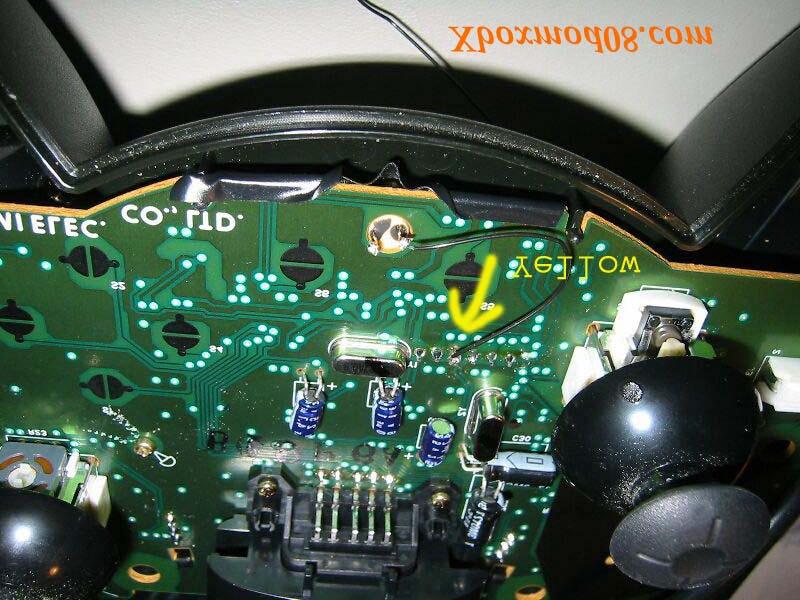
2 use the switch that is in the on state, and when its pressed it breaks the signal. You can now continue.) My switch matched perfectly. You may have to adjust it a little bit if you get a different switch. Mount it like this: Then put some electrical tape over it so it will stick. You can also use superglue. Next you have to solder a wire from one of the legs on the switch to the connection of the yellow wire (It isn t used. Some say it s for a light pen, which you don t have anyway). If you have a different layout of the circuit board you have to find out which leg is connected to the yellow wire. Just remove the white connector on the bottom side of the circuit board and use the multimetre to check where the yellow wire connects on the other side of the board. When you have found it you just solder the wire from that leg to the leg on the switch. You can see how I did in this picture. "Yellow" is where the yellow wire from the other side connects.
3


4 Next you have to solder the other leg to Ground. I did this to a solder point next to the other wire. Note: Make the wires a little bit longer than mine. Now it s time to put it back together. To make it fit properly you have to remove some plastic from the other half of the controller. Just cut the little plastic thing on the picture, like you did on the other half of the controller.
: You connect the yellow wire to Pin 19 (which is Component) - S-video (AV Pack): You connect the yellow wire to Pin 19 - Component (AV Pack): You connect the yellow")
5 It should look something like this when it s done. Now, open up your Xbox console. Remove the motherboard and turn it upside down. There are four different modes you should know about. If you use: - Composite (AV Pack): You connect the yellow wire to Pin 19 (which is Component) - S-video (AV Pack): You connect the yellow wire to Pin 19 - Component (AV Pack): You connect the yellow wire to Pin SCART (AV Pack): You connect the yellow wire to preferably Pin 18 Now I will explain what and where the pins are. If you take a look at the picture below of the AV output you can see that it is numbered from This is where you put your AV cable. So you can use a multimetre to check where for example pin 17 in this picture is connected on the motherboard. Note: If you use Scart, jump down a few pages and I ll explain how you will install it. I will do this for both Composite and Component because I will buy the Component Av pack later, and I don t want to redo everything. You can use just one of these methods. I suppose you can use only pin 18 for both of these video modes. I haven t tested that though. I guess all motherboards are the same so I will show you where the pins are.

6 As you can see above I have soldered the black wire to pin 19 because I use Composite right now. I have also soldered the white wire to pin 17 for when I get the Component Av Pack. Now, turn the motherboard again. Remove the yellow wire that goes from the first controller port on the Xbox. I then soldered the black wire (Pin 19) to the first controller port (Gameport Nr 1, in the picture), and then removed the yellow wire from the second controller port (Gameport Nr 2, in the picture) and soldered it together with the white wire (Pin 17). So when I use the Standard AV Pack (composite) I put the controller into the first controller port, when I then get the High Definition AV Pack (Component) I just put the controller into the second controller port and the reset switch will still work. Note: If you don t plan to change AV Pack you only have to remove one of the yellow wires, not both. I did it because I ll get the High Definition AV Pack later. The discoverer of this feature explains how it works. Thanks MajahTom! All you have to do is to momentarily switch between two dissimilar video modes e.g. composite and HDTV. This is done by changing the modes on the AV cable (by grounding or leaving open Mode1 (pin17), Mode2 (pin18) or Mode3 (pin19). I currently use the std AV cable... hence composite... pin 17 (mode1) is connected to pin 5 (mode1 gnd). To make a reset switch I added a momentary pushbutton which connects pin 19 (mode3) to pin 7 (mode3 gnd) - setting it to component while the button is pressed. When the button is pressed, the XBox detects the video mode change and resets the xbox. MajahTom.

7 Before you close the Xbox take some electrical tape to protect the connections between the wires so that it doesn t get in contact with the motherboard or something else. Now close the Xbox and do a test run. It works flawlessly on my Xbox and it s the coolest thing I ve done so far on the Xbox. Scart users I haven t tried this yet and will update it with pictures when I get to do this. But here is how you do it. Open up the Xbox, turn the motherboard upside-down and connect a cable from pin 18 (you can see the pin layout in a picture below) to the yellow cable on Game port #1. Then open your AV plug and connect a cable from Pin 18 (you can see the layout in the picture below) to pin 5, 6 or 7 which is ground. Put the plug back together. Then you have to change the switch in the controller to a momentary switch that breaks the conenction and you should now have a working reset switch for the Scart AV Pack.
8 Pin Description Pin Description 1 Audio Right 13 Vcc 2 Audio Right GND 14 Audio Left 3 SP-DIF Digital Audio 15 Audio Left GND 4 V-Sync (VGA Mode) 16 H Sync (VGA Mode) 5 Mode GND 17 Mode Select 1 6 Mode GND 18 Mode Select 2 7 Mode GND 19 Mode Select 3 8 GND v 9 Variable 21 Pin 22 GND 10 Pin 9 GND 22 Variable 11 Variable 23 Pin 24 GND 12 Pin 11 GND 24 Variable Greetings goes to: - MajahTom for discovering this feature and all the help concerning it. - xmltok for pointing out that the yellow wire could be used in the Game Controller - Dreamcazman for the info on how to install if you use the Scart cable. - EvolutionX team who have made a fantastic job on there Bios. - Xboxhacker.net and Xbox-scene.com for having the two best Xbox websites on the scene. - Gamesx.com for contributing with the picture of the pin layout of the AV output. - Tim Rettmann for the research of the pin layout. - All developers/programmers for all the cool utilities. - Microsoft for putting in that extra yellow wire :) Expect more from the Xboxmod08 Team Of Sweden. Best regards, Xboxmod08.com
Atari PICO Composite Mod Board Installation Instructions:
 Atari PICO Composite Mod Board Installation Instructions: Installation Guide 6 Switch Atari 2600 6 Switch Video Mod Installation Guide Disclaimer: I am not responsible for any damage done to your Atari.
This is a support manual for the GBS-8220 which comes in a one vga port and two port version.
 This is a support manual for the GBS-8220 which comes in a one vga port and two port version. When using this board you want to read all the information in this document there are many common mistakes/issues
UAV Ultimate Atari Video A7800
 UAV Ultimate Atari Video A7800 Basic Install guide because this is really easy mod to do! The UAV is a wonderful piece of tech for what it can do. To summarize, the UAV is a replacement video encoder and
Please read and keep this manual. It contains important information on the safe and proper use of your X2VGA Plus High Definition VGA Pack.
 ENG 1.00 2004/7 Please read and keep this manual. It contains important information on the safe and proper use of your X2VGA Plus High Definition VGA Pack. The term X2VGA+ TM in this manual means the product,
Video to SXGA Converter Box ID#475
 Video to SXGA Converter Box ID#475 Operation Manual Introduction The Video to SXGA Converter Box is a composite video signal. S-Video signal and YCbCr signal format converter for AV System (Such as DVD.
Dissolve Control Programming : Projector/Dissolve Control Hook-Up
 Product Information Title: Operating Equipment: Dissolve Control Programming Projector/Dissolve Control Hook-up Sync Track Hook-up Converting Tapes to Digital Sync Signals Recording Signals 80 Vs 140 Slide
Warning and Safety Information. FCC Information
 Installation Manual Warning and Safety Information FCC Information This device complies with FCC Rules Part 15 Operation and is subject to the following two conditions: (1) This device may not cause harmful
Step What to do Expected result What to do if test fails Component tested 1 Visual inspection. Board is accurately assembled
 Fox Delta Amateur Radio Projects & Kits AAZ-0914A 50MHZ Antenna Analyzer Testing Guide by Tony / I2TZK SWR Analyzer 4 steps for a quick test Step What to do Expected result What to do if test fails Component
AirWave. Communication Module. Installation. Operations Manual PR&E Revision B 1/01
 & TM Communication Module Installation & Operations Manual PR&E 7-33 Revision B /0 Installation The Communication Module features 0 individual momentary buttons. The first 6 buttons (counting from the
How To Build Megavolt s Small Buffered JTAG v1.2
 How To Build Megavolt s Small Buffered JTAG v1.2 Abstract A JTAG cable should be considered mandatory equipment for any serious tester. It provides a means to backup the information in the receiver and
Wall Ball Setup / Calibration
 Wall Ball Setup / Calibration Wall projection game 1 Table of contents Wall Projection Ceiling Mounted Calibration Select sensor and display Masking the projection area Adjusting the sliders What s happening?
DIY Guide - Building Franky v1.1, the SEGA Audio and Videocard for MSX
 DIY Guide - Building Franky v1.1, the SEGA Audio and Videocard for MSX 2015 FRS & MSXpró. Translation by FRS and Supersoniqs. Table of Contents Introduction... 3 Materials needed... 3 Audio volume boost...
VGA Extender LR EXT-VGA-141LR. User s Manual
 VGA Extender LR EXT-VGA-141LR User s Manual Congratulations on your purchase of the VGA Extender LR. Your complete satisfaction is very important to us. Gefen Gefen delivers innovative, progressive computer
1 Unpack. Taking the TV Out of the Box. Included in this Box. Stand Parts and Cables. Remote Control. Also included
 MIC TV SEARCH KEYPAD SOURCE VOL VOICE CH RETURN GUIDE EXIT CH.LIST SMART HUB 3D MTS CC P.SIZE MENU INFO 1 Unpack Taking the TV Out of the Box Warning: Do not touch the TV s screen when you take it out
Edge Connector Light Level Detector
 Description This is a simple tutorial demonstrating how to use a Kitronik edge connector breakout with the BBC micro:bit. The tutorial will cover measuring ambient light levels with an LDR and dimming
Low Voltage Wall Mount Touch Panel RGB Controller
 Low Voltage Wall Mount Touch Panel RGB Controller MODEL: LT-10S-WH Product Specifications Summary The Low Voltage Wall Mount RGB Controller is mainly used to control constant voltage LED products such
Video Streamer Modifications
 CB Electronics Video Streamer Modifications CB Electronics Loddonside, Lands End House, Beggars Hill Road, Charvil, Berks RG10 0UD, UK Tel: +44 (0)118 9320345, Fax: +44 (0)118 9320346 URL: www.colinbroad.com
TeamWork Kits Installation Guide
 TX 0 RX COM +5V APARATUS US TeamWork Kits Installation Guide TeamWork 400 and TeamWork 600 Kits The TeamWork 400 and TeamWork 600 kits consist of an HDMI switcher, system controller, Cable Cubby, and cables
Bas Gialopsos Atari PureVideo Encoder Module 2600VECr5.2
 Bas Gialopsos 2014 Atari PureVideo Encoder Module 2600VECr5.2 Table of Contents Description Disclaimer Technical and Signal Identification Installation Instructions Tools Required Caution Installation
replacement systems. PT-F200 Series Permanent-Installation Projectors Please make these projectors your very first recommendations as new or
 2008 January Approach Book Please make these projectors your very first recommendations as new or replacement systems. Permanent-Installation Projectors Are some of your customers hesitant to switch to
1 Unpack. Taking the TV Out of the Box. Included in this Box. Stand Parts and Cables. Remote Control. Also included
 1 Unpack Taking the TV Out of the Box Warning: Do not touch the TV s screen when you take it out of the box. Hold it by its edges only. If you touch the screen, you can cause the TV panel to crack. Included
Woodman s Guide To Get Video On Your Touchscreen Display For LR3/Discovery 3 or Range Rover 2006+
 Woodman s Guide To Get Video On Your Touchscreen Display For LR3/Discovery 3 or Range Rover 2006+ This guide is assumes that you have a LR3/Disco3 with the dealer fit DVD overhead system and want to get
AC334A. VGA-Video Ultimate BLACK BOX Remote Control. Back Panel View. Side View MOUSE DC IN BLACK BOX ZOOM/FREEZE POWER
 AC334A BLACK BOX 724-746-5500 VGA-Video Ultimate BLACK BOX 724-746-5500 Zoom Position PAL ZOOM/FREEZE POWER FREEZE ZOOM NTSC/PAL SIZE RESET POWER Size Power Remote Control DC IN MOUSE MIC IN AUDIO OUT
COLOUR CHANGING USB LAMP KIT
 TEACHING RESOURCES SCHEMES OF WORK DEVELOPING A SPECIFICATION COMPONENT FACTSHEETS HOW TO SOLDER GUIDE SEE AMAZING LIGHTING EFFECTS WITH THIS COLOUR CHANGING USB LAMP KIT Version 2.1 Index of Sheets TEACHING
"shell" digital storage oscilloscope (Beta)
") "shell" digital storage oscilloscope (Beta) 1. Main board: solder the element as the picture shows: 2. 1) Check the main board is normal or not Supply 9V power supply through the connector J7 (Note: The
"shell" digital storage oscilloscope (Beta) 1. Main board: solder the element as the picture shows: 2. 1) Check the main board is normal or not Supply 9V power supply through the connector J7 (Note: The
Pelican PL-957. Adding additional Tos Link (Digital Optical) inputs, and / or IR Remote
 inputs, and / or IR Remote") Pelican PL-957 Adding additional Tos Link (Digital Optical) inputs, and / or IR Remote Table of Contents: Background;... 2 Section 1: Adding TosLink receivers... 3 Section 2: Adding Remote Capability...
Pelican PL-957 Adding additional Tos Link (Digital Optical) inputs, and / or IR Remote Table of Contents: Background;... 2 Section 1: Adding TosLink receivers... 3 Section 2: Adding Remote Capability...
GRANT RF CONTROL CENTER INSTALLATION INSTRUCTIONS Always disconnect battery while servicing or modifying the electrical system of the vehicle.
 GRANT RF CONTROL CENTER INSTALLATION INSTRUCTIONS Always disconnect battery while servicing or modifying the electrical system of the vehicle. You will need standard hand tools, a Test Light and a Digital
apple Service Source Apple Cinema HD Display 23" LCD (ADC) 11 April Apple Computer, Inc. All rights reserved.
 11 April Apple Computer, Inc. All rights reserved.") apple Service Source Apple Cinema HD Display 23" LCD (ADC) 11 April 2003 2003 Apple Computer, Inc. All rights reserved. apple Service Source Take Apart Apple Cinema HD Display 23" LCD (ADC) 2003 Apple
apple Service Source Apple Cinema HD Display 23" LCD (ADC) 11 April 2003 2003 Apple Computer, Inc. All rights reserved. apple Service Source Take Apart Apple Cinema HD Display 23" LCD (ADC) 2003 Apple
0.56" 4 Digital Blue LED Panel Meter (rescalable) User s Guide
 User s Guide") 0.56" 4 Digital Blue LED Panel Meter (rescalable) User s Guide 2004-2009 Sure Electronics Inc. ME-SP037B_Ver1.0 0.56" 4 DIGITAL BLUE LED PANEL METER (RESCALABLE) USER S GUIDE Table of Contents Chapter
0.56" 4 Digital Blue LED Panel Meter (rescalable) User s Guide 2004-2009 Sure Electronics Inc. ME-SP037B_Ver1.0 0.56" 4 DIGITAL BLUE LED PANEL METER (RESCALABLE) USER S GUIDE Table of Contents Chapter
E4200 Antenna Installation Instructions: 1. Soldering required (here is the list of tools you will need)
") Thank you for purchasing the 6 Antenna Mod Kit for your Linksys router. First we will show you how to install the antennas for your router. Next we will teach you how to setup the DD-WRT firmware which
Thank you for purchasing the 6 Antenna Mod Kit for your Linksys router. First we will show you how to install the antennas for your router. Next we will teach you how to setup the DD-WRT firmware which
Lesson Sequence: S4A (Scratch for Arduino)
") Lesson Sequence: S4A (Scratch for Arduino) Rationale: STE(A)M education (STEM with the added Arts element) brings together strands of curriculum with a logical integration. The inclusion of CODING in STE(A)M
Lesson Sequence: S4A (Scratch for Arduino) Rationale: STE(A)M education (STEM with the added Arts element) brings together strands of curriculum with a logical integration. The inclusion of CODING in STE(A)M
1 Unpack. Taking the TV Out of the Box. Included in this Box. Stand Parts and Cables. Remote Control. Also included
 MIC TV SEARCH KEYPAD SOURCE VOL VOICE CH RETURN GUIDE EXIT CH.LIST SMART HUB 3D MTS CC P.SIZE MENU INFO 1 Unpack Taking the TV Out of the Box Warning: Do not touch the TV s screen when you take it out
Part names (continued) Remote control
 Remote control") Introduction Part names (continued) Remote control (1) STANDBY ( 25) (1) (2) ON ( 25) (3) (3) ID - 1 / 2 / 3 / 4 s ( 18) (4) (4) COMPUTER 1 ( 27) (7) (5) COMPUTER 2 * (8) (6) COMPUTER 3 * (10) (13) (7)
Introduction Part names (continued) Remote control (1) STANDBY ( 25) (1) (2) ON ( 25) (3) (3) ID - 1 / 2 / 3 / 4 s ( 18) (4) (4) COMPUTER 1 ( 27) (7) (5) COMPUTER 2 * (8) (6) COMPUTER 3 * (10) (13) (7)
VGA & Stereo Audio CAT5 Extender With Chainable Output ITEM NO.: VE10DAL, VE02ALR, VE02DALS
 VGA & Stereo Audio CAT5 Extender With Chainable Output ITEM NO.: VE10DAL, VE02ALR, VE02DALS VE010DAL is designed for VGA +Stereo Audio/Digital Audio signal over cost effective CAT5 cable to instead of
RMS 8424S Quick Start
 VIEWSIZE THE WORLD RMS 8424S Quick Start Standard 4 unit rack mount size 8 inch LCD 2 1024 3 (RGB) 600 16:9 / 4:3 adjustable SDI/HDMI embedded audio output via 3.5mm earphone socket Support SDI/DVI audio
Welcome to your. Wireless transmitter and receiver kit
 Welcome to your Wireless transmitter and receiver kit Your Handykam camera Transmitter/Receiver (T/R) kit is designed to transmit and receive both pictures and sound (video and audio) with a choice of
apple Service Source Apple Studio Display 17" LCD (ADC) Updated 6 Decenber Apple Computer, Inc. All rights reserved.
 Updated 6 Decenber Apple Computer, Inc. All rights reserved.") apple Service Source Apple Studio Display 17" LCD (ADC) Updated 6 Decenber 2004 2003 Apple Computer, Inc. All rights reserved. apple Service Source Take Apart Apple Studio Display 17" LCD (ADC) 2003 Apple
apple Service Source Apple Studio Display 17" LCD (ADC) Updated 6 Decenber 2004 2003 Apple Computer, Inc. All rights reserved. apple Service Source Take Apart Apple Studio Display 17" LCD (ADC) 2003 Apple
HD-CONVERTER USER MANUAL MODEL GBS-8220
 Page 1 of 6 HD-CONVERTER USER MANUAL MODEL GBS-8220 CGA/EGA/YUV TO VGA CONVERTER VERSION 3.0 CONVERT OR REPLACE YOUR OLD STYLE MONITORS WITH NEWER VGA CRTS OR LCD SCREENS QUICKLY AND EASILY! FEATURES:
COPYRIGHT NOVEMBER-1998
 Application Notes: Interfacing AG-132 GPS with G-858 Magnetometer 25430-AM Rev.A Operation Manual COPYRIGHT NOVEMBER-1998 GEOMETRICS, INC. 2190 Fortune Drive, San Jose, Ca 95131 USA Phone: (408) 954-0522
Fixed Audio Output for the K2 Don Wilhelm (W3FPR) & Tom Hammond (NØSS) v August 2009
 & Tom Hammond (NØSS) v August 2009") Fixed Audio Output for the K2 Don Wilhelm (W3FPR) & Tom Hammond (NØSS) v. 2.1 06 August 2009 I have had several requests to provide a fixed audio output from the K2. After looking at the circuits that
Fixed Audio Output for the K2 Don Wilhelm (W3FPR) & Tom Hammond (NØSS) v. 2.1 06 August 2009 I have had several requests to provide a fixed audio output from the K2. After looking at the circuits that
Instruction Manual for the & Electronic Bingo Blower
 Instruction Manual for the 17212 & 17214 Electronic Bingo Blower The directions in this manual when referring to the 17212 are referring to software version 2.83 (you can find what version your blower
VGA Extender LR EXT-VGA-141LR. User s Manual
 VGA Extender LR EXT-VGA-141LR User s Manual ASKING FOR ASSISTANCE Technical Support: Telephone (818) 772-9100 (800) 545-6900 Fax (818) 772-9120 Technical Support Hours: 8:00 AM to 5:00 PM Monday thru
IPad 4 REPAIR GUIDE. Version Edition
 IPad 4 REPAIR GUIDE Version 1 2016 Edition IPad 4 REPAIR GUIDE LCD AND DIGITIZER REPLACEMENT RiAna Soto Repair Training Specialist rsoto@cellairis.com FOR EVERY REPAIR MAKE SURE TO COMPLETE, INITIAL, AND
IPad 3 (glass) REPAIR GUIDE. Version Edition
 REPAIR GUIDE. Version Edition") IPad 3 (glass) REPAIR GUIDE Version 1 2016 Edition IPad 4 REPAIR GUIDE LCD AND DIGITIZER REPLACEMENT RiAna Soto Repair Training Specialist rsoto@cellairis.com FOR EVERY REPAIR MAKE SURE TO COMPLETE, INITIAL,
IPad 3 (glass) REPAIR GUIDE Version 1 2016 Edition IPad 4 REPAIR GUIDE LCD AND DIGITIZER REPLACEMENT RiAna Soto Repair Training Specialist rsoto@cellairis.com FOR EVERY REPAIR MAKE SURE TO COMPLETE, INITIAL,
Syntor X Flash Memory Module Revision C
 Syntor X Flash Memory Module Revision C The PIEXX SynXFlash memory module, along with the supplied PC software, replaces the original SyntorX code plugs and allows you to easily set modify and update your
Make sure you have these items handy
 Quick Start Guide TV Av Info Exit R DSL 1 2 RESET ETH1 ETH2 ETH3 ETH4 PWR Make sure you have these items handy What we ve sent you: A. Yes TV by Fetch box B. Ethernet Cable (3m) (You ll receive 3 of these
1 Unpack. Taking the TV Out of the Box. Included in this Box. Remote Control. Stand Parts and Cables. Also included
 1 Unpack Taking the TV Out of the Box Warning: Do not touch the TV s screen when you take it out of the box. Hold it by its edges only. If you touch the screen, you can cause the TV panel to crack. Included
Remote Control. degraded, causing unreliable operation. The recommended effective distance for remote operation is about 16 feet (5 meters).
.") Media Streaming Sound Bar RTS736W User Manual Remote Control using the remote control Point the remote control at the REMOTE SENSOR located on the unit (see Front Panel illustration for precise location).
Media Streaming Sound Bar RTS736W User Manual Remote Control using the remote control Point the remote control at the REMOTE SENSOR located on the unit (see Front Panel illustration for precise location).
Building the ChronoDot Calendar Reminder
 Building the ChronoDot Calendar Reminder Being very forgetful and married is not a good combination. Luckily my wife comes up with solutions and suggested that we make some sort of reminder that would
HP Media Center Extender Quick Start Guide Start Here
 HP Media Center Extender Quick Start Guide Start Here 2004, Hewlett-Packard Development Company, L.P. Printed in Welcome to the Media Center Extender Setup Required! You must upgrade to Microsoft Windows
WDP02 Wireless FHD Kit User Manual
 WDP02 Wireless FHD Kit User Manual Copyright Copyright 2015 by BenQ Corporation. All rights reserved. No part of this publication may be reproduced, transmitted, transcribed, stored in a retrieval system
COLOR TFT LCD MONITOR WITH MULTI-TOUCH FUNCTION Manual
 COLOR TFT LCD MONITOR WITH MULTI-TOUCH FUNCTION Manual DEAR CUSTOMERS Thank you for choosing our TFT LCD (liquid crystal display) monitor. This product employs integrate circuits, low power consumption,
VectorVGA Tempest User Manual
 VectorVGA Tempest User Manual 2 Notice Regarding This Product WARNING! To install this product you should: Be familiar with safe handling procedures for electronic components. Be able to use hand tools
Online Service Manuals available at:
 CAB PRECOR P80 The Precor P80 console with the media adapter kit can now control ANY cable, satellite or IPTV set top box using the CAB from Broadcastvision Entertainment. Online Service Manuals available
Car-Solutions.com. Warning / Caution. Warning. Caution
 Video Interface for Volkswagen Golf 7 with Discover Media Update Date 2013.11.14 Model User Guide QPI-G7-MAIN-V2.0 Firmware Date 131028 Warning / Caution Warning Caution When installing the main unit,
CAT System on the MIC socket for Yaesu FT-897/857
 CAT System on the MIC socket for Yaesu FT-897/857 (it doesn't apply to the FT-817) By Filippo Tondinelli, IZØINX When an automatic tuner like the Yaesu CF-30 is used with a Yaesu FT-897 or FT-857, it will
STD-525T PRECISION TIMER
 FN:STD525TM1.DOC STD-525T PRECISION TIMER DESCRIPTION The STD-525T Precision Timer measures and displays accurate elapsed time in minutes, seconds, tenths of seconds, and hundredths of seconds (MM.SS.TH)
Model SP-HDMI-2A. HDMI Video Splitter - 1 input x 2 output Allows display of HDMI A/V signal 2 HDTV Displays CUSTOMER SUPPORT INFORMATION
 Model SP-HDMI-2A HDMI Video Splitter - 1 input x 2 output Allows display of HDMI A/V signal 2 HDTV Displays UMA1102 Rev. C CUSTOMER SUPPORT INFORMATION Order toll-free in the U.S. 800-959-6439 FREE technical
Robot Preemptive Troubleshooting
 Robot Preemptive Troubleshooting In FIRST Robotics Competion, robots take a lot of stress while driving around the field. It is important to make sure that connections are tight, parts are bolted securely
Manual #: UMA1074 Rev. 2 October, Hall Research Technologies, Inc 1163 Warner Ave. Tustin, CA 92780
 Component Video / VGA Over UTP Video Transmission Systems Manual #: UMA1074 Rev. 2 October, 2007 Hall Research Technologies, Inc 1163 Warner Ave. Tustin, CA 92780 Table of Contents 1.0 GENERAL DESCRIPTION...
Camera Setup Instructions
 Camera Setup Instructions Hopefully this document will help new MallinCam owners set up their systems and get them to successful first light more quickly. Through the use of images, I hope to describe
Snail Fence InteleCell Deployment Guide
 Snail Fence InteleCell Deployment Guide Preparation 1. Prepare deployment trip by making sure you have the following materials and tools when you fly up to the site: InteleCell NEMA Enclsoure (grey plastic
The video-signals on 128K ZX Spectrum models
 The video-signals on 128K ZX Spectrum models This document describes some fairly easy video-enhancements that should result in perfectly clear and crisp pictures from your ZX Spectrum! (Document version:
Here are some pictures of the WE jumper on the different model Xbox s. V1.0 and V1.1 Xbox PCB s V1.2 and V1.3 Xbox PCB s
 To reflash the onboard TSOP in the Xbox, two jumpers must be installed to allow the MCPX chip to control the WE (Write Enable) and OE (Output Enable) lines. The V1.2 and V1.3 Xbox s have a smaller Flash
Operating instructions Through-beam sensor. OJ51xx / / 2004
 Operating instructions Through-beam sensor OJ5xx UK 7098 / 0 07 / 004 Contents Function and features... Installation... Installation of the supplied mounting fixture...4 Electrical connection...4 Setting
... User Guide - Revision /23/04. H Happ Controls. Copyright 2003, UltraCade Technologies UVC User Guide 1/23/2004
 H Happ Controls 106 Garlisch Drive Elk Grove, IL 60007 Tel: 888-289-4277 / 847-593-6130 Fax: 847-593-6137 wwwhappcontrolscom User Guide - Revision 201 01/23/04 Copyright 2003, UltraCade Technologies UVC
LINE IN, LINE OUT AUDIO IN, AUDIO OUT FIXED, VARIABLE TO TV, VIDEO IN, VIDEO OUT Sony Electronics Inc. All rights reserved.
 This is a general recommendation based on the information you provided. You can customize the connections to suit your individual preferences and viewing habits. Some hookup recommendations have two cable
Hi! Let s get started.
 Hi! Let s get started. What s in the box Roku Streaming Stick TM What you need Roku Ready TM TV (or other device) High speed Internet Wireless Router Know your Streaming Stick [MHL CONNECTOR] Plugs into
Coaxial Cable wiring tips and tricks, from BAMF Manufacturing LLC
 Coaxial Cable wiring tips and tricks, from BAMF Manufacturing LLC As a way of saying thank you for your purchase, we have put together a brief manual, in which we will provide some basic tricks and tips
A Huf Puf VFO stabilizer for the YAESU FT-707
 A Huf Puf VFO stabilizer for the YAESU FT-707 Bruno Beckers ON6AB Page 1 The Yaesu FT707 is a good object to add a Huff Puff VFO stabilizer developed by the late Klaas Spaargaren PA0KSB. The version of
3950 NW 120 th Ave, Coral Springs, FL TEL FAX RGBv2 NTV-KIT885.
 3950 NW 120 th Ave, Coral Springs, FL 33065 TEL 561-955-9770 FAX 561-955-9760 www.nav-tv.com info@nav-tv.com RGBv2 NTV-KIT885 Overview The RGBv2 adds an aftermarket backup camera to the factory navigation
VGA AUDIO SWITCHER S MANUAL
 VGA AUDIO SWITCHER S MANUAL Milestone s VGA Audio Switcher is a unit whereby multiple (2/4/8/16) VGA + Audio can be switched to two (2) or multiple (simultaneous) VGA + Audio output. The switchers are
LED Interior Lighting Sets Instruction Manual (380mm)
") LED Interior Lighting Sets Instruction Manual 50703 (380mm) Manual version 1.0 December 2010 General Features The ESU LED Interior lighting set 50703 uses the most contemporary technique to supply its
LED Interior Lighting Sets Instruction Manual 50703 (380mm) Manual version 1.0 December 2010 General Features The ESU LED Interior lighting set 50703 uses the most contemporary technique to supply its
USER S MANUAL (1/2) (Functions and connections)
 (Functions and connections)") English USER S MANUAL (1/2) (Functions and connections) WIDE PLASMA DISPLAY P42VCA30W/P42VCA30E WITH OPTIONAL VIDEOBOARD (P-TE1100/P-TE1110/P-TE1120/P-TE1130) HE4VS01W/HE4VS01E WITH OPTIONAL VIDEOBOARD
English USER S MANUAL (1/2) (Functions and connections) WIDE PLASMA DISPLAY P42VCA30W/P42VCA30E WITH OPTIONAL VIDEOBOARD (P-TE1100/P-TE1110/P-TE1120/P-TE1130) HE4VS01W/HE4VS01E WITH OPTIONAL VIDEOBOARD
USER MANUAL FOR CABLE RECEIVER KAON KCF-200CO KAON KCF-H220SCO
 USER MANUAL FOR CABLE RECEIVER KAON KCF-200CO KAON KCF-H220SCO SECURITY INSTRUCTIONS FOR USING THE RECEIVER Always fallow these instructions to avoid risk of injury or damaging the equipment. Before cleaning
Uni700 LCD Controller
 Landmark Technology Inc. Uni700 LCD Controller For TFT LCDs with Resolution up to 1,920 x 1,200 (Version A) January 27, 2009 1 1. Introduction The Uni700 controller board is designed for LCD panels of
Elite Screens Frequently Asked Questions. Screens FAQs
 Elite Screens Frequently Asked Questions Screens FAQs Q1: How can I extend my RJ-45 accessory such as my 3-way wall switch, 5-12v trigger, and IR "eye" sensor? A: You can extend the length of your accessory
The BBC micro:bit: What is it designed to do?
 The BBC micro:bit: What is it designed to do? The BBC micro:bit is a very simple computer. A computer is a machine that accepts input, processes this according to stored instructions and then produces
AITech ProA/V Media Extender Mini. User Manual
 AITech ProA/V Media Extender Mini User Manual Package Contents x 1 x 1 Infrared (IR) eye cable x 1 Remote antenna x 1 Audio/Video cable x 2 Power adaptors (DC6V) x 2 User manual x 1 Note: The transmitter
1x12 VGA & Audio over CAT5 Splitter
 SP-9112 1x12 VGA & Audio over CAT5 Splitter User Manual rev: 160322 Made in Taiwan Safety and Notice The SP-9112 1x12 VGA & Audio over CAT5 Splitter has been tested for conformance to safety regulations
1. Unlocking your FT847 to get 4m ( for those who already have unlocked one, please move to chapter 2).
.") Modification Yaesu FT-847 dla pasma 70MHz Part II practical solution v. 1.0 (Oct 2013) Greg SP3RNZ sp3rnz@wp.pl PA mod idea by Marc PA1O TX/RX mod idea by Hellar ES1II/8 This article describing how to
Modification Yaesu FT-847 dla pasma 70MHz Part II practical solution v. 1.0 (Oct 2013) Greg SP3RNZ sp3rnz@wp.pl PA mod idea by Marc PA1O TX/RX mod idea by Hellar ES1II/8 This article describing how to
Lawnbott No Signal /Blackout Troubleshooting Guide
 The Lawnbott No Signal error can be the most difficult problem to resolve. There are two types of No Signal errors, persistent and intermittent. Persistent means the Lawnbott display shows No Signal as
Electronic Equipment Manual For 101, 102, 301 & 302 Azrieli Theatre For further information, please visit our website at:
 Electronic Equipment Manual For 101, 102, 301 & 302 Azrieli Theatre For further information, please visit our website at: http://www.carleton.ca/ims/ 2 TABLE OF CONTENTS: Topic Page # Logging onto the
LINE IN, LINE OUT AUDIO IN, AUDIO OUT FIXED, VARIABLE TO TV, VIDEO IN, VIDEO OUT Sony Electronics Inc. All rights reserved.
 This is a general recommendation based on the information you provided. You can customize the connections to suit your individual preferences and viewing habits. Some hookup recommendations have two cable
AVE-301T AVE-301R AVE-304T AVE-308T AVE-316T
 VGA and Audio CAT-5 AV Extender AVE-301T AVE-301R AVE-304T AVE-308T AVE-316T User Manual V1.2 www.databay.com.tw www.green-box.com.tw Contents 1. Product Introduction...4 2. Product Features...5 3. System
Multi-Key v2.4 Multi-Function Amplifier Keying Interface
 Multi-Key v2.4 Multi-Function Amplifier Keying Interface ASSEMBLY & OPERATION INSTRUCTIONS INTRODUCTION The Harbach Electronics, LLC Multi-Key is a multi-function external device designed for the safe
 Switch Panel Backlight Issues (white backlighting that illuminates the label text) Notes: the backlighting is controlled by a 'PANEL LIGHTS' button at the Galley 8 button switch panel) Backlighting is
InfiniTV 4 Installation Instructions
 InfiniTV 4 Installation Instructions 1. Obtain a CableCARD from your cable TV service provider 1. Call your cable TV service provider and tell them you need a multi-stream CableCARD (M-Card) for a Ceton
Operating instructions Retro-reflective sensor. OJ50xx laser / / 2010
 Operating instructions Retro-reflective sensor OJ50xx laser 70481 / 00 05 / 010 Contents 1 Preliminary note3 1.1 Symbols used 3 Safety instructions 3 4 Installation 4 4.1 Installation of the supplied mounting
Sega MegaDrive 1 RGB Bypass Installation Guide Rev 1.1
 Sega MegaDrive 1 RGB Bypass Installation Guide Rev 1.1 This step by step guide describes the Installation of the open source Voultar RGB Bypass Amplifier board for the original SEGA MegaDrive/Genesis 1.
VGA CAT-5 1:8 Distribution S VGA CAT-5 Distribution R. EXT-VGA-CAT5-148S EXT-VGA-CAT5-148R User Manual
 VGA CAT-5 1:8 Distribution S VGA CAT-5 Distribution R EXT-VGA-CAT5-148S EXT-VGA-CAT5-148R User Manual INTRODUCTION Congratulations on your purchase of the VGA CAT-5 1:8 Distribution S. Your complete satisfaction
P-2 Installing the monitor (continued) Carry out as necessary
 Carry out as necessary") P-2 Installing the monitor (continued) Carry out as necessary Using the monitor without the bezel MDT552S satisfies the UL requirements as long as it is used with the bezel attached. When using the monitor
P-2 Installing the monitor (continued) Carry out as necessary Using the monitor without the bezel MDT552S satisfies the UL requirements as long as it is used with the bezel attached. When using the monitor
MSP430 JTAG / BSL connectors
 MSP430 JTAG / BSL connectors (PD010A05 Rev-4: 23-Nov-2007) FAQ: Q: I have a board with the standard TI-JTAG pinhead. Can I use your programmer to flash my MSP430Fxx device? A: Yes. You can use any of our
Quad 7-segment display board
 Quad 7-segment display board www.matrixtsl.com EB008 Contents About this document 3 Board layout 3 General information 4 Circuit description 4 Protective cover 5 Circuit diagram 6 2 Copyright About this
Commissioning Guide. firepickdelta. Commissioning Guide. Written By: Neil Jansen firepickdelta.dozuki.com Page 1 of 22
 firepickdelta Commissioning Guide Written By: Neil Jansen 2017 firepickdelta.dozuki.com Page 1 of 22 Step 1 Pre-Requisites Before commissioning, please make sure ALL of the following steps have been completed,
NX APPLICATION NOTE Led Guided Assembly Connector Pinning with Continuity
 NX APPLICATION NOTE Led Guided Assembly Connector Pinning with Continuity Background Many wire harness connectors are designed to use a push-click-pull method of wire insertion. This method requires the
MyFlyDream TeleFlyPro V1.04
 MyFlyDream TeleFlyPro V1.04 www.myflydream.com Notes Thank you for purchasing the MyFlyDream TeleFlyPro (hereinafter referred to as TFPro). Please follow this manual to get familiar with the TFPro and
INSTALLATION INSTRUCTIONS WIRED REMOTE CONTROL USING COAX CABLE U-WRC-C
 Tel-Quip PH: 713-728-0625; FAX: 713-456-2512 www.telquip.com INSTALLATION INSTRUCTIONS 10-17-2013 WIRED REMOTE CONTROL USING COAX CABLE U-WRC-C Thank you for using the Tel-Quip Wired Remote Control. This
Building a MidiBox LCD Cable
 Building a MidiBox LCD Cable By Jim Henry, 3-Apr-2004 An LCD panel may be connected to the Core module by a 16 conductor flat ribbon cable. A 16 pin insulation displacement connector (IDC) terminates one
Rebis Audio Ltd. RA226 Digital Sampler User Guide
 Rebis Audio Ltd. RA226 Digital Sampler User Guide CONTENTS Page Caution 2 Powering Up 2 Controls 3, 4 Detailed Description Input Level Set 5 Recording 5 Sampling 5 Multiple Samples 6 Editing 6 Playback