RF Characterization Report
|
|
|
- Wesley Shepherd
- 5 years ago
- Views:
Transcription

1 BNC7T-J-P-xx-ST-EMI BNC7T-J-P-xx-RD-BH1 BNC7T-J-P-xx-ST-TH1 BNC7T-J-P-xx-ST-TH2D BNC7T-J-P-xx-RA-BH2D Mated with: RF179-79SP1-74BJ Description: 75 Ohm BNC Board Mount Jacks Samtec, Inc All Rights Reserved
2 Table of Contents Introduction... 1 Product Description... 1 Results Summary... 3 VSWR Data... 3 Return Loss Data... 8 Test Procedure Fixturing VSWR Testing Equipment Samtec, Inc Page: ii All Rights Reserved
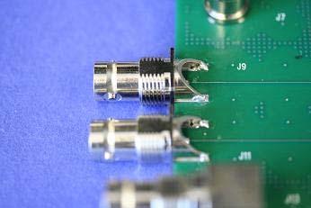
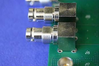
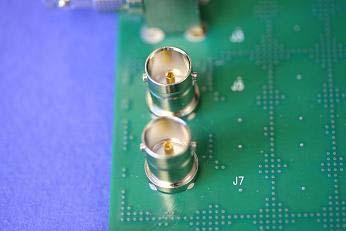
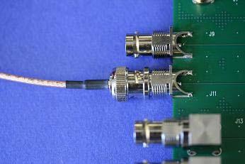
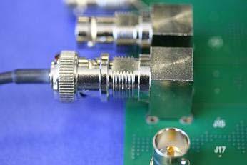
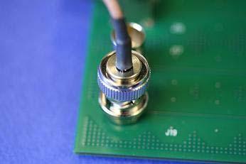
3 Introduction This testing was performed to evaluate the electrical performance of the BNC7T series 75- Ohm BNC Board Mount Connectors. VSWR measurements were made over the frequency range from 130 MHz to 6 GHz for mated pairs of connectors. All measurements were made utilizing test boards specifically designed for this project and are referred to as test board in this report. The test boards were identified as PCB TST-01, PCB TST and PCB TST. The measured results include not only the mated connectors but also the termination effects of each. Product Description Each test sample is mounted to a test board, which is a 62-mil thick 4-layer stackup with microstrip traces having a nominal impedance of 75 Ohms. Each connector type has an optimized footprint (compensation) incorporated into the PCB design to facilitate improved impedance match over the frequency range of interest. The test board traces were located either on the top or the bottom of the PCB. Each BNC7T connector was tested by mating to a 75-Ohm BNC male connector, which was part of either a RF179-79SP1-74BJ or RF179-74BJ3-74Sp test cable assembly. Either one or four samples of each connector type were tested. The actual part numbers that were tested are shown in Table 1. A representative sample picture is shown in Figure 1. Part Number Board Mount Connector Type Compensation PCB Trace Location BNC7T-J-P-XX-RD-BH1 Right Angle Gen 2 Bottom BNC7T-J-P-XX-ST-TH1 Vertical Mount Gen 2 Bottom BNC7T-J-P-XX-ST-EM1 End Launch Gen 2 Top BNC7T-J-P-XX-RD-BH1 Right Angle Gen 1 Top BNC7T-J-P-XX-ST-TH1 Vertical Mount Gen 1 Top BNC7T-J-P-XX-ST-TH2 Vertical Mount Gen 3 Top BNC7T-J-P-XX-ST-TH2 Vertical Mount Gen 3 Bottom BNC7T-J-P-XX-RA-BH2D Right Angle Gen 3 Bottom BNC7T-J-P-XX-RA-BH2D Right Angle Gen 3 Top Table 1: Sample Descriptions Samtec, Inc Page: 1 All Rights Reserved

4 Figure 1: Test Sample Configuration Samtec, Inc Page: 2 All Rights Reserved
5 Results Summary VSWR Data VSWR measurements were performed over the frequency range from 130 MHz to 6 GHz. All measurements were performed with the board mount jack mated to a 75-Ohm BNC male connector that was part of a 75-Ohm flexible cable assembly. The table below lists the maximum VSWR of each mated pair measured over the frequency range tested. Board Mount Connector BNC7T-J-P-XX-RD-BH1 Right Angle BNC7T-J-P-XX-ST-TH1 Vertical Mount BNC7-J-P-XX-ST-EM1 End Launch BNC7T-J-P-XX-ST-TH2D Vertical Mount BNC7T-J-P-XX-RA-BH2D Right Angle Compensation Gen 3 Gen 2 Gen 1 Max Max Max Sample VSWR Sample VSWR Sample VSWR J J J J J J J J J J J J J J J J J J J J J J J J Table 2: VSWR Data Samtec, Inc Page: 3 All Rights Reserved
6 VSWR Data Plots VSWR BNC7T-J-P-XX-RA-BH1 Right Angle FREQ (GHz) J1 J2 J3 J4 Figure 2: Gen 2 BNC7T-J-P-XX-RD-BH1 VSWR VSWR BNC7T-J-P-XX-ST-TH1 Vertical Mount J5 J6 J7 J8 1.0 FREQ (GHz) Figure 3: Gen 2 BNC7T-J-P-XX-ST-TH1 VSWR Samtec, Inc Page: 4 All Rights Reserved
7 VSWR BNC7T-J-P-XX-ST-EM1 End Launch J9 J10 J11 J FREQ (GHz) Figure 4: Gen 2 BNC7T-J-P-XX-ST-EM1 VSWR VSWR BNC7T-J-P-XX-RA-BH1 Right Angle J13 J14 J15 J FREQ (GHz) Figure 5: Gen 1 BNC7T-J-P-XX-RA-BH1 VSWR Samtec, Inc Page: 5 All Rights Reserved
8 VSWR BNC7T-J-P-XX-ST-TH1 Vertical Mount J17 J18 J19 J FREQ (GHz) Figure 6: Gen 1 BNC7T-J-P-XX-ST-TH1 VSWR VSWR BNC7T-J-P-XX-ST-TH2D Vertical Mount FREQ (GHz) J1 J5 Figure 7: Gen 3 BNC7T-J-P-XX-ST-TH2D VSWR Samtec, Inc Page: 6 All Rights Reserved
9 BNC7T-J-P-XX-RA-BH2D Right Angle VSWR FREQ (GHz) J1 J5 Figure 8: Gen 3 BNC7T-J-P-XX-RA-BH2D VSWR Samtec, Inc Page: 7 All Rights Reserved
10 Return Loss Data Return Loss measurements were performed over the frequency range from 130 MHz to 6 GHz. All measurements were performed with the board mount jack mated to a 75-Ohm BNC male connector that was part of a 75-Ohm flexible cable assembly. Figure 9-15 shows the measured return loss data for board mount BNC connectors. Figures 9 through 15 also include the SMPTE 424M-2006 limit line for reference. SMPTE 424M-2006 is a specification for 3 Gb/s serial data used for digital video transmission. All the BNC7T coaxial connectors combined with their optimized footprints easily met the requirements of this digital video transmission specification BNC7T-J-P-XX-RA-BH1 Right Angle SMPTE Limit J1 J2 J3 J4 Return Loss (db) Frequency (GHz) Figure 9: Gen 2 BNC7T-J-P-XX-RA-BH1 Return Loss Samtec, Inc Page: 8 All Rights Reserved
11 BNC7T-J-P-XX-ST-TH1 Vertical Mount SMPTE Limit J5 J6 J7 J8 Return Loss (db) Frequency (GHz) Figure 10: Gen 2 BNC7T-J-P-XX-ST-TH1 Return Loss BNC7T-J-P-XX-ST-EM1 End Launch SMPTE Limit J9 J10 J11 J12 Return Loss (db) Frequency (GHz) Figure 11: Gen 2 BNC7T-J-P-XX-ST-EM1 Return Loss Samtec, Inc Page: 9 All Rights Reserved
12 BNC7T-J-P-XX-RA-BH1 Right Angle SMPTE Limit J13 J14 J15 J16 Return Loss (db) Frequency (GHz) Figure 12: Gen 1 BNC7T-J-P-XX-RA-BH1 Return Loss BNC7T-J-P-XX-ST-TH1 Vertical Mount SMPTE Limit J17 J18 J19 J20 Return Loss (db) Frequency (GHz) Figure 13: Gen 1 BNC7T-J-P-XX-ST-TH1 Return Loss Samtec, Inc Page: 10 All Rights Reserved
13 0-10 BNC7T-J-P-XX-ST-TH2D Vertical Mount SMPTE Limit J1 J5 Return Loss (db) Frequency (GHz) Figure 14: Gen 3 BNC7T-J-P-XX-ST-TH2D Return Loss BNC7T-J-P-XX-RA-BH2D Right Angle SMPTE Limit J1 J5 Return Loss (db) Frequency (GHz) Figure 15: Gen 3 BNC7T-J-P-XX-RA-BH2D Return Loss Samtec, Inc Page: 11 All Rights Reserved
14 Test Procedure Fixturing: All measurements were performed using a test board, which has 75- microstrip traces (nominal impedance). There is a connector at each end of the trace. During an actual measurement one connector of a trace serves as part of the mated pair device under test (DUT) and the other connector provides a means of terminating the far end. A vector network analyzer is used to perform the measurements and is connected to the DUT as follows. One end of a 30-inch long 50- SMA (m/m) test cable is attached to the network analyzer. The second end of the SMA test cable attaches to a SMA (f) to N (m) adapter. The adapter attaches to a 50- N (f) to 75- N (m) matching pad. The matching pad attaches to a 75-- N (f) to BNC (m) adapter. The adapter attaches to the first BNC end of a RF test cable. The BNC (m) end of the 75- test cable attaches to the DUT. The far end of the microstrip line of the DUT is terminated in a 75- load. The 75- cable BNC (m) connector and the board mount jack comprise the mated pair under test. Figure 16: Test Setup for VSWR Measurement Samtec, Inc Page: 12 All Rights Reserved
15 VSWR Testing All VSWR measurements were made using an HP 8720A vector network analyzer. It was set for a 201-point measurement response over the frequency range from 130 MHz to 13.1 GHz to allow use of the low-pass step response time domain transform capability. Response averaging was turned on and set to 8. An S11 1-port measurement calibration was performed at the end of the SMA test cable. The SMA cable was attached to the type N 50- to 75- matching pad, which attached to the DUT by means of a 75- test cable as described previously. The far end of the test board is terminated in a 75- load. The measured response is viewed in the time domain using the low-pass step transform and the real data format. Gating is turned on. The Gate Start and Stop flags are set around the response of the mated pair of interest. See Figure 17 below. The response format is set to linear magnitude (reflection coefficient), and the time domain transform is turned off (but the gate remains on). In converting back to the frequency domain, the effects of the response outside the Gate are removed. The reflection coefficient data are read by a computer over the GPIB and mathematically corrected (multiplied by a factor of 3.72) to account for the two-way attenuation of the matching pad. The data is written in ASCII format to a data file. Data above 6 GHz is not used. Note that the attenuation effects of the 75- test cable are not taken into account and are a source of error. Based on published nominal attenuation values for RG-179 coaxial cable, it is estimated that the error in return loss at 5 GHz is about 1 db. This is equivalent to an error of 0.05 for a VSWR of 1.3 or an error of 0.08 for a VSWR of 1.5. The errors are negative, which means the measured results are lower than the actual values. Samtec, Inc Page: 13 All Rights Reserved

16 BNC7T-J-P-xx-ST-TH1 Figure 17. Typical time domain response showing gate placement. Samtec, Inc Page: 14 All Rights Reserved
17 Equipment HP 8720A Network Analyzer Pasternak PE N(f) to 75- N (m) Matching Pad Samtec, Inc Page: 15 All Rights Reserved
RF Characterization Report
 CJT Series Circular RF Twinax Jack CJT-T-P-HH-ST-TH1 CJT-T-P-HH-RA-BH1 Mated With C28S-XX.XX-SPS8-SPS8 Description: Fully Mated Circular RF Shielded Twisted Pair Twinax Cable Assembly Samtec Inc. WWW.SAMTEC.COM
RF Characterization Report
 HDBNC Series RF Connector HDBNC-J-P-GN-ST-EM1 HDBNC-J-P-GN-ST-BH1 HDBNC-J-P-GN-ST-TH1 Description: 75 Ohm True 75 TM High Density BNC Straight Jack, Edge Mount or Through-hole Samtec Inc. WWW.SAMTEC.COM
Microwave Interconnect Testing For 12G-SDI Applications
 DesignCon 2016 Microwave Interconnect Testing For 12G-SDI Applications Jim Nadolny, Samtec jim.nadolny@samtec.com Corey Kimble, Craig Rapp Samtec OJ Danzy, Mike Resso Keysight Boris Nevelev Imagine Communications
TEST REPORT T&M Research Products, Inc. Model W11K20-3.5s Ω by M. E. Gruchalla PE, December 6, 2008
 TEST REPORT T&M Research Products, Inc. Model W11K20-3.5s-0.0002433Ω by M. E. Gruchalla PE, December 6, 2008 1. INTRODUCTION A T&M Research Products, Inc. Model W11K20-3.5s-0.0002433Ω Current Viewing Resistor
Application Note. 3G SDI Evaluation Board. Revision Date: July 2, 2009
 3G SDI Evaluation Board Revision Date: July 2, 2009 Copyrights and Trademarks Copyright 2009 Samtec, Inc. Copyright 2009 Brioconcept Consulting Developed in collaboration between Samtec, Inc Brioconcept
Optimizing BNC PCB Footprint Designs for Digital Video Equipment
 Optimizing BNC PCB Footprint Designs for Digital Video Equipment By Tsun-kit Chin Applications Engineer, Member of Technical Staff National Semiconductor Corp. Introduction An increasing number of video
GT Dual-Row Nano Vertical Thru-Hole High Speed Characterization Report For Differential Data Applications
 GT-16-97 Dual-Row Nano Vertical Thru-Hole For Differential Data Applications 891-007-15S Vertical Thru-Hole PCB 891-001-15P Cable Mount Revision History Rev Date Approved Description A 8/31/2016 R. Ghiselli/G.
30 GHz Attenuator Performance and De-Embedment
 30GHz De-Embedment Application Note - Page 1 of 6 Theory of De-Embedment. Due to the need for smaller packages and higher signal integrity a vast majority of todays RF and Microwave components are utilizing
GT Dual-Row Nano Vertical SMT High Speed Characterization Report For Differential Data Applications
 GT-16-95 Dual-Row Nano Vertical SMT For Differential Data Applications 891-011-15S Vertical SMT PCB 891-001-15P Cable Mount Revision History Rev Date Approved Description A 6/3/2016 R. Ghiselli/D. Armani
Test Systems. Typical JFW Systems. Matrix switches Programmable assemblies Switch assemblies Manual attenuator assemblies Power divider assemblies
 Test Systems This section of our catalog showcases some standard JFW test systems. However, we understand that everyone s system requirements are unique. For this reason, we can design a system to suit
Keysight Technologies De-Embedding and Embedding S-Parameter Networks Using a Vector Network Analyzer. Application Note
 Keysight Technologies De-Embedding and Embedding S-Parameter Networks Using a Vector Network Analyzer Application Note L C Introduction Traditionally RF and microwave components have been designed in packages
Microwave Interconnect Testing For 12G SDI Applications
 TITLE Microwave Interconnect Testing For 12G SDI Applications Jim Nadolny, Samtec Image Corey Kimble, Craig Rapp - Samtec OJ Danzy, Mike Resso - Keysight Boris Nevelev - Imagine Communications Microwave
ENGINEERING COMMITTEE Interface Practices Subcommittee AMERICAN NATIONAL STANDARD ANSI/SCTE
 ENGINEERING COMMITTEE Interface Practices Subcommittee AMERICAN NATIONAL STANDARD ANSI/SCTE 48-3 2011 Test Procedure for Measuring Shielding Effectiveness of Braided Coaxial Drop Cable Using the GTEM Cell
ENGINEERING COMMITTEE Interface Practices Subcommittee AMERICAN NATIONAL STANDARD ANSI/SCTE Mainline Pin (plug) Connector Return Loss
 Connector Return Loss") ENGINEERING COMMITTEE Interface Practices Subcommittee AMERICAN NATIONAL STANDARD ANSI/SCTE 125 2007 Mainline Pin (plug) Connector Return Loss NOTICE The Society of Cable Telecommunications Engineers (SCTE)
ENGINEERING COMMITTEE Interface Practices Subcommittee AMERICAN NATIONAL STANDARD ANSI/SCTE 125 2007 Mainline Pin (plug) Connector Return Loss NOTICE The Society of Cable Telecommunications Engineers (SCTE)
12G Broadcast connectors
 12G Broadcast connectors Delivering 12G in a single punch www.coax-connectors.com Welcome to COAX 12G BNC Plug return loss COAX Connectors Ltd is a leading UK designer, manufacturer and supplier of high
Samtec Final Inch PCIE Series Connector Differential Pair Configuration Channel Properties
 Samtec Final Inch PCIE Series Connector Differential Pair Configuration Channel Properties Scott McMorrow, Director of Engineering Jim Bell, Senior Signal Integrity Engineer Page 1 Introduction and Philosophy
Non Magnetic Connectors
 Non Magnetic Connectors Johnson Components builds coaxial connectors using innovative materials and design to provide Mil Spec Performance at a commercial price. Now we offer our Non Magnetic Connectors
MCX - 75 Ohm Connectors
 133-8333-001 4 133-8333-401 4 133-8334-001 4 133-8334-401 4 133-8433-001 3 133-8433-101 3 133-8434-001 3 133-8445-001* 3 133-8445-101* 3 133-8701-201 5 133-8701-211 5 133-8701-301 6 133-8701-311 6 133-8701-401
Practical De-embedding for Gigabit fixture. Ben Chia Senior Signal Integrity Consultant 5/17/2011
 Practical De-embedding for Gigabit fixture Ben Chia Senior Signal Integrity Consultant 5/17/2011 Topics Why De-Embedding/Embedding? De-embedding in Time Domain De-embedding in Frequency Domain De-embedding
RF (Wireless) Fundamentals 1- Day Seminar
 Fundamentals 1- Day Seminar") RF (Wireless) Fundamentals 1- Day Seminar In addition to testing Digital, Mixed Signal, and Memory circuitry many Test and Product Engineers are now faced with additional challenges: RF, Microwave and
RF (Wireless) Fundamentals 1- Day Seminar In addition to testing Digital, Mixed Signal, and Memory circuitry many Test and Product Engineers are now faced with additional challenges: RF, Microwave and
JD725A Cable and Antenna Analyzer - Dual Port
 COMMUNICATIONS TEST & MEASUREMENT SOLUTIONS JD725A Cable and Antenna Analyzer - Dual Port Key Features Portable and lightweight handheld instrument Built-in wireless frequency bands as well as the most
Analyze Frequency Response (Bode Plots) with R&S Oscilloscopes Application Note
 with R&S Oscilloscopes Application Note") Analyze Frequency Response (Bode Plots) with R&S Oscilloscopes Application Note Products: R&S RTO2002 R&S RTO2004 R&S RTO2012 R&S RTO2014 R&S RTO2022 R&S RTO2024 R&S RTO2044 R&S RTO2064 This application
Analyze Frequency Response (Bode Plots) with R&S Oscilloscopes Application Note Products: R&S RTO2002 R&S RTO2004 R&S RTO2012 R&S RTO2014 R&S RTO2022 R&S RTO2024 R&S RTO2044 R&S RTO2064 This application
Agilent MOI for HDMI 1.4b Cable Assembly Test Revision Jul 2012
 Revision 1.11 19-Jul 2012 Agilent Method of Implementation (MOI) for HDMI 1.4b Cable Assembly Test Using Agilent E5071C ENA Network Analyzer Option TDR 1 Table of Contents 1. Modification Record... 4 2.
75 Ohm N Male Connector Crimp/Solder Attachment for RG6
 75 Ohm N Male Connector Crimp/Solder Attachment for RG6 RF Connectors Technical Data Sheet PE4508 Configuration N Male Connector 75 Ohms Straight Body Geometry Features Max Operating Frequency 15 GHz Good
ELECTRICAL PERFORMANCE REPORT
 CIRCUITS & DESIGN ELECTRICAL PERFORMANCE REPORT DENSIPAC 4 ROW Date: 06-12-2006 Circuits & Design EMEA Circuits & Design 1/21 06/12/2006 1 INTRODUCTION... 3 2 CONNECTORS, TEST BOARDS AND TEST EQUIPMENT...
Non Magnetic Connectors Product Catalog
 Non Magnetic Connectors Product Catalog Introduction Johnson s Non-Magnetic Connector Additions Offer Solutions to MR Imaging Technology Johnson, a product line of Cinch Connectivity Solutions, has expanded
RF/Microwave Connectors & Cable Assemblies
 RF/Microwave Connectors & Cable Assemblies Emerson Network Power Connectivity Solutions Connectivity Solutions To our valued customers: For over 80 years, Johnson Components and Cambridge Products have
Interface Practices Subcommittee SCTE STANDARD SCTE Hard Line Pin Connector Return Loss
 Interface Practices Subcommittee SCTE STANDARD SCTE 125 2018 Hard Line Pin Connector Return Loss NOTICE The Society of Cable Telecommunications Engineers (SCTE) / International Society of Broadband Experts
Amphenol RF Connectors
 Amphenol RF Connectors 007 901-9601 SMA PLUGS & ANGLE PLUGS FOR FLEXIBLE CABLE 50X IMPEDANCE Conn. Attachment RG-/U Outer Inner 901-9511-12SF Dbl. Braid RG-316 Plug Br. Solder $17.49 901-9531-12SF Angle
De-embedding Gigaprobes Using Time Domain Gating with the LeCroy SPARQ
 De-embedding Gigaprobes Using Time Domain Gating with the LeCroy SPARQ Dr. Alan Blankman, Product Manager Summary Differential S-parameters can be measured using the Gigaprobe DVT30-1mm differential TDR
Product Introduction. Duplexer Box MN2555A. Signal Analyzer MS2830A. Ver.1.0
 Product Introduction Duplexer Box MN2555A Signal Analyzer MS2830A Ver.1.0 Duplexer Box MN2555A Duplexer Box MN2555A Connecting MN2555A, Signal Analyzer MS2830A, and USB Power Sensor *The shape of the accessory
The Custom Interconnect Leader TM
 LC Series.5.188.685 ELECTRICAL Nominal Impedance: Frequency Range: Voltage Rating: Dielectric Withstanding Voltage: Insulation Resistance: VSWR: 50 ohms DC to 1.0 GHz 5,000 volts rms 3,000 volts rms 5,000
GaAs MMIC Double Balanced Mixer. Description Package Green Status
 GaAs MMIC Double Balanced Mixer MM132HSM 1. Device Overview 1.1 General Description The MM132HSM is a GaAs MMIC double balanced mixer that is optimized for high frequency applications. MM1-832HSM is a
Virtual Thru-Reflect-Line (TRL) Calibration
 Calibration") Virtual Thru-Reflect-Line (TRL) By John E. Penn Introduction In measuring circuits at microwave frequencies, it is essential to have a known reference plane, particularly when measuring transistors whose
Virtual Thru-Reflect-Line (TRL) By John E. Penn Introduction In measuring circuits at microwave frequencies, it is essential to have a known reference plane, particularly when measuring transistors whose
TR-Plus T/R Switch Assembly and Operation Manual. Introduction
 TR-Plus T/R Switch Assembly and Operation Manual Revised: 7 February 2015 2015 Tucson Amateur Packet Radio Corporation Introduction The TAPR TR-Plus is a transmit/receive ( T/R ) switch that connects a
SMA - 50 Ohm Connectors
 Alphabetical Index 142-0593-001 6 142-0593-006 6 142-0593-401 6 142-0593-406 6 142-0594-001 6 142-0594-006 6 142-0594-401 6 142-0594-406 6 142-0693-001 4 142-0693-006 4 142-0693-051 5 142-0693-056 5 142-0693-101
Type "N" Connectors. Type "N" Interface Dimensions
 Type "N" Connectors The type N series coaxial connectors were originally designed as medium-size low voltage constant impedance 50 OHM connectors. Type N connectors found immediate popularity for microwave
MAX2660/MAX2661/MAX2663/MAX2671 Evaluation Kits
 9-382; Rev ; 9/99 MAX2660/MAX266/MAX2663/MAX267 General Description The MAX2660/MAX266/MAX2663/MAX267 evaluation kits simplify evaluation of the MAX2660/MAX266/ MAX2663/MAX267 upconverter s. They enable
!Ill ~ 168. Model490 Dual Input, Dual Trace Automatic Peak Power Meter
 Model490 Dual Input, Dual Trace Automatic Peak Power Meter No other power meter can offer you these features: Help Mode: A Help Mode feature has been added to the Model 490 Automatic Peak Power Meter.
ENGINEERING COMMITTEE
 ENGINEERING COMMITTEE Interface Practices Subcommittee AMERICAN NATIONAL STANDARD ANSI/SCTE 04 2014 Test Method for F Connector Return Loss NOTICE The Society of Cable Telecommunications Engineers (SCTE)
Advanced Test Equipment Rentals ATEC (2832)
") E stablished 1981 Advanced Test Equipment Rentals www.atecorp.com 800-404-ATEC (2832) Technical Datasheet Scalar Network Analyzer Model 8003-10 MHz to 40 GHz The Giga-tronics Model 8003 Precision Scalar
E stablished 1981 Advanced Test Equipment Rentals www.atecorp.com 800-404-ATEC (2832) Technical Datasheet Scalar Network Analyzer Model 8003-10 MHz to 40 GHz The Giga-tronics Model 8003 Precision Scalar
Low Loss RG 402 Equivalent
 421-671 Low Loss RG 402 Equivalent Section 10 Low Loss RG 402 Equivalent In applications that require the bendability of solid dielectric, but with the low loss that only a low density Teflon dielectric
Application Note AN39
 AN39 9380 Carroll Park Drive San Diego, CA 92121, USA Tel: 858-731-9400 Fax: 858-731-9499 www.psemi.com Vector De-embedding of the PE42542 and PE42543 SP4T RF Switches Introduction Obtaining accurate measurement
Converters Series Tri-Band Frequency Converters. Back to Multiband. Specifications Upconverters Downconverters Phase Noise Options Rear Panel
 R Back to Multiband Converters 9700 Series Tri-Band Frequency Converters 9700 SERIES TRI-BAND FREQUENCY CONVERTERS The MITEQ frequency converters are designed for advanced satellite communication systems
TGL2210-SM_EVB GHz 100 Watt VPIN Limiter. Product Overview. Key Features. Applications. Functional Block Diagram. Ordering Information
 .5 6 GHz Watt VPIN Limiter Product Overview The Qorvo is a high-power receive protection circuit (limiter) operating from.5-6ghz. Capable of withstanding up to W incident power levels, the allows < dbm
Monoblock RF Filter Testing SMA, In-Fixture Calibration and the UDCK
 Application Note AN1008 Introduction Monoblock RF Filter Testing SMA, In-Fixture Calibration and the UDCK Factory testing needs to be accurate and quick. While the most accurate (and universally available)
PRODUCT CATALOGUE 2010 Accessories
 PRODUCT CATALOGUE 2010 Accessories Challange the distance with Inmak the antenna company CONTENTS CONNECTORS 110 ADAPT RS 115 SURGE PROTECTOR SP-1 116 SPLITTER INM SP2.4-2 117 SPLITTER INM SP5.8-2 117
USB-TG124A Tracking Generator User Manual
 USB-TG124A Tracking Generator User Manual Signal Hound USB-TG124A User Manual 2017, Signal Hound, Inc. 35707 NE 86th Ave La Center, WA 98629 USA Phone 360.263.5006 Fax 360.263.5007 This information is
HDRFI Series Tensolite High-Performance Cable & Interconnect Systems. High Density RF Interconnect
 HDRFI Series Tensolite High-Performance Cable & Interconnect Systems High Density RF Interconnect HDRFI is a patented Tensolite connection system that transfers high frequency signals through a unique
R&S ZVA-Zxx Millimeter-Wave Converters Specifications
 R&S ZVA-Zxx Millimeter-Wave Converters Specifications Data Sheet Version 19.00 CONTENTS Definitions... 3 General information... 4 Specifications... 5 Test port... 5 Source input (RF IN)... 5 Local oscillator
Calibrating attenuators using the 9640A RF Reference
 Calibrating attenuators using the 9640A RF Reference Application Note The precision, continuously variable attenuator within the 9640A can be used as a reference in the calibration of other attenuators,
Features. = +25 C, IF= 100 MHz, LO= +13 dbm* Parameter Min. Typ. Max. Min. Typ. Max. Units
 Features Passive Double Balanced Topology High LO/RF Isolation: 48 db Low Conversion Loss: 7 db Wide IF Bandwidth: DC - GHz Robust 1,000V esd, Class 1C Typical Applications The is ideal for: Point-to-Point
Ultra-Small Surface Mount Coaxial Connectors mm Mated Height
 All non- products have been discontinued, or will be discontinued soon. the products status on the Hirose website search at www.hirose-connectors.com, or contact your Hirose sales representative. NEW Ultra-Small
DUT ATE Test Fixture S-Parameters Estimation using 1x-Reflect Methodology
 DUT ATE Test Fixture S-Parameters Estimation using 1x-Reflect Methodology Jose Moreira, Advantest Ching-Chao Huang, AtaiTec Derek Lee, Nvidia Conference Ready mm/dd/2014 BiTS China Workshop Shanghai September
MPI Cable Selection Guide
 MPI Cable Selection Guide MPI engineers focus to provide on optimal cable solutions taking into account a number of requirements specific for wafer-level measurement systems: optimal cable length, cable
Coaxial Cable Termination
 Coaxial Cable Termination RF one-step BNC/TNC connectors Applications RF one-step BNC/TNC connectors are single-piece assemblies for terminating the center conductor and the braid of a broad range of coaxial
SERIES HPQN CONNECTORS
 SERIES HPQN CONNECTORS 1 DESCRIPTION Patented in 2008 by Anoison Electronics, the HPQN is a quick locking version of the widely used type N connector. By replacing the threaded interface of the original
SUHNER QMA SUBMINIATURE CONNECTORS
 SUHNER QMA SUBMINIATURE CONNECTORS Description Content Page SUHNER QMA coaxial connectors are available with 50 Ω impedance. The frequency range extends to 11 GHz, depending on the connector and cable
Series SMPM-T. Description. Compatibility. Content. Interface dimensions (mm/inches) SMPM-T male (pin contact), smooth bore
 SMPM-T male (pin contact), smooth bore") Series Description The is the smallest threaded open source connector on the market. Its unique and innovative combination of a MIL- STD-348 SMPM female interface connector together with a retractable
Series Description The is the smallest threaded open source connector on the market. Its unique and innovative combination of a MIL- STD-348 SMPM female interface connector together with a retractable
Keysight Method of Implementation (MOI) for VESA DisplayPort (DP) Standard Version 1.3 Cable-Connector Compliance Tests Using E5071C ENA Option TDR
 for VESA DisplayPort (DP) Standard Version 1.3 Cable-Connector Compliance Tests Using E5071C ENA Option TDR") Revision 1.00 February 27, 2015 Keysight Method of Implementation (MOI) for VESA DisplayPort (DP) Standard Version 1.3 Cable-Connector Compliance Tests Using E5071C ENA Option TDR 1 Table of Contents 1.
Revision 1.00 February 27, 2015 Keysight Method of Implementation (MOI) for VESA DisplayPort (DP) Standard Version 1.3 Cable-Connector Compliance Tests Using E5071C ENA Option TDR 1 Table of Contents 1.
Orbital 694XA Series. Ka BAND EXTERNAL REFERENCE LNB with rear anchor posts. Wide range of Frequencies and Bandwidths LNB 1855R 1000 XA-WN60
 Orbital 694XA Series Ka BAND EXTERNAL REFERENCE LNB with rear anchor posts Wide range of Frequencies and Bandwidths How to order an Orbital 694XA Series Ka Ext Ref LNB Frequencies (GHz): LO Input Output
PERFORMANCE SPECIFICATION SHEET CONNECTORS, PLUGS, ELECTRICAL, COAXIAL, RADIO FREQUENCY (SERIES SMA (CABLED) - PLUG, PIN CONTACT, CLASS 2)
 - PLUG, PIN CONTACT, CLASS 2)") INCH-POUND MIL-PRF-39012/55G 6 February 2008 SUPERSEDING MIL-PRF-39012/55G 6 January 2006 PERFORMANCE SPECIFICATION SHEET CONNECTORS, PLUGS, ELECTRICAL, COAXIAL, RADIO FREQUENCY (SERIES SMA (CABLED) -
INCH-POUND MIL-PRF-39012/55G 6 February 2008 SUPERSEDING MIL-PRF-39012/55G 6 January 2006 PERFORMANCE SPECIFICATION SHEET CONNECTORS, PLUGS, ELECTRICAL, COAXIAL, RADIO FREQUENCY (SERIES SMA (CABLED) -
INTER SERIES ADAPTERS INTRODUCTION & 2.4 MM, 2.9 MM INTER SERIES
 INTRODUCTION & 2.4 MM, 2.9 MM INTER SERIES Inter series coaxial adapters are some of the more common components used in RF, microwave and wireless applications. OEM s and manufacturing and engineering
Network Analyzer Terminal - Scalar Network Analyzer
 Network Analyzer Terminal - Scalar Network Analyzer Dave Collins AD7JT Ozarkcon 2015 April 10-11 George Heron N2APB www.midnightdesignsolutions.com/nat What can YOU do with a Scalar Network Analyzer? Test
Materials Connector part Material Finish
 Materials Connector part Material Finish Bodies Brass Nickel or Gold Center Contact Male: Brass Gold Female: Brass, Phosphor Bronze, or Beryllium Copper Insulator Delrin or Teflon N/A Crimp ferrule Annealed
SCR Series Synthesized Converters L, C, X, Ku, and DBS Bands
 SCR Series Synthesized Converters L, C, X, Ku, and DBS Bands Key Features Three-Year Warranty Excellent Phase Noise Performance External 5 or 10 MHz Reference Input Network Interface RS-232/-422/-485 Serial
GaAs MMIC Double Balanced Mixer
 Page 1 The is a highly linear passive GaAs double balanced MMIC mixer suitable for both up and down-conversion applications. As with all Marki Microwave mixers, it features excellent conversion loss, isolation
Keysight Technologies Method of Implementation (MOI) for BroadR-Reach Link Segment Tests Using E5071C ENA Option TDR
 for BroadR-Reach Link Segment Tests Using E5071C ENA Option TDR") Revision 2.00 August 28, 2014 BroadR-Reach Link Segment Keysight Technologies Method of Implementation (MOI) for BroadR-Reach Link Segment Tests Using E5071C ENA Option TDR 1 Table of Contents 1. Revision
Revision 2.00 August 28, 2014 BroadR-Reach Link Segment Keysight Technologies Method of Implementation (MOI) for BroadR-Reach Link Segment Tests Using E5071C ENA Option TDR 1 Table of Contents 1. Revision
GaAs DOUBLE-BALANCED MIXER
 The MM1-312S is a high linearity passive double balanced MMIC mixer. The S diode offers superior 1 db compression, two tone intermodulation performance, and spurious suppression to other GaAs MMIC mixers.
PI3PCIE2612-A. High Bandwidth, 6-Differential Channel 1:2 DP/PCIe Gen2 Display Mux, ATX Pinout. Features. Description
 Features 6 Differential Channel, 1 to 2 demux that will support 5.0Gbps PCIexpress Gen2 signals on one path, and DP 1.1 signals on the second path Insertion Loss for high speed channels @ 5.0 Gbps: -5.0dB
Highlights: Cables & Adaptors. Stock Cable Assemblies Custom Cable Assemblies Multi-conductor Cables Patch Panels Connector Adaptors
 Cables & Adaptors Highlights: Stock Cable Assemblies Custom Cable Assemblies Multi-conductor Cables Patch Panels Adaptors www.pcb.com 716-684-0001 PCB Piezotronics, Inc. Automotive Sensors Division Common
GaAs MMIC Double Balanced Mixer
 Page 1 The is a passive GaAs double balanced MMIC mixer suitable for both up and down-conversion applications. As with all Marki Microwave mixers, it features excellent conversion loss, isolation and spurious
The Art of Engineering
 The Art of Engineering Functionality DPST Switch DPST Sensing Switch Transfer Switch Passive Splitter Ethernet Switch ASI 3G Switch or DA E/T Switch Optical Switch up to 006 MHz L-Band Broadband Ethernet
Agilent 5345A Universal Counter, 500 MHz
 Agilent 5345A Universal Counter, 500 MHz Data Sheet Product Specifications Input Specifications (pulse and CW mode) 5356C Frequency Range 1.5-40 GHz Sensitivity (0-50 deg. C): 0.4-1.5 GHz -- 1.5-12.4 GHz
R&S ZVA-Zxx Millimeter-Wave Converters Specifications
 ZVA-Zxx_dat-sw_en_5214.2033.22_umschlag.indd 1 Data Sheet 13.00 Test & Measurement R&S ZVA-Zxx Millimeter-Wave Converters Specifications 28.01.2013 15:08:06 CONTENTS General information... 3 Definitions...
HDSI Series Tensolite High-Performance Cable & Interconnect Systems
 HDSI Series Tensolite High-Performance Cable & Interconnect Systems Tensolite's High Density Shielded Interconnect Products Tensolite s HDSI and HDSI-DP assemblies use ribbonized coaxial cable, matched
User s Guide Rev 1.0
 User s Guide Rev 1.0 Plug and Play Kit for De-Embedding Software Algorithms Verification Evaluate the Accuracy of De-Embedding Algorithms Purchase Kits Direct from DVT Solutions, LLC Brian Shumaker sales@gigaprobes.com
High Density BNC Connectors
 High Density BNC Connectors Spacing HD-BNCTM High Density Cable 8 mm (.315 ) 64 interconnects in 2.5 x 2.5 Standard Cable 9.5 mm (.374 ) 36 interconnects in 2.5 x 2.5 Standard BNC 15.9 mm (.625 ) 16 interconnects
PAM-1840 Preamplifier Operation Manual
 PAM-1840 Preamplifier Operation Manual 1 TABLE OF CONTENTS INTRODUCTION 3 GENERAL INFORMATION 4 SPECIFICATIONS 4 OPERATING INSTRUCTIONS 5 MAINTENANCE 6 2 INTRODUCTION BEFORE APPLYING POWER Review this
Ultra Small Surface Mount Coaxial Connectors 1.4mm Mated Height
 NEW Ultra Small Surface Mount Coaxial Connectors 1.4mm Mated Height W.FL Series Further downsizing of FL series in response to the market needs. Occupied Mounting Area.0.0 Features 1. Mounting area of
CS Series Motorized Coaxial Transfer Switches
 CS Series Motorized Coaxial Transfer Switches Features 3 or 4 port configurations Three port application require only the addition of a shorting cap Non-volatile position memory VSWR
Ultra Small Surface Mount Coaxial Connectors 1.4mm Mated Height
 All non- products have been discontinued, or will be discontinued soon. Please check the products status on the Hirose website search at www.hirose-connectors.com, or contact your Hirose sales representative.
SERIES BNC 50, COAXIAL MINIATURE CONNECTORS
 SERIES BNC 50, COAXIAL MINIATURE CONNECTORS DESCRIPTION CONTENTS PAGE HUBER+SUHNER BNC is still one of the most popular connector series, featuring a two stud bayonet coupling mechanism, which is particularly
TGA2218-SM GHz 12 W GaN Power Amplifier
 Applications Satellite Communications Data Link Radar Product Features Functional Block Diagram Frequency Range: 13.4 16.5 GHz PSAT: > 41 dbm (PIN = 18 dbm) PAE: > 29% (PIN = 18 dbm) Large Signal Gain:
CM-1UTP CAMERA MASTER UTP ADAPTOR
 CM-1UTP CAMERA MASTER UTP ADAPTOR INSTRUCTION BOOK CM-1UTP.ISB TABLE OF CONTENTS FORWARD 2 VIDEO STANDARDS 2 COAXIAL CABLE vs UTP WIRE CABLE 3 MEASUREMENT 3 MOUNTING THE CM1-UTP ADAPTOR 3 UTP WIRE CABLE
Orbital Ka-ISO. Ext Ref Ka LNB with integrated isolator. Orbital Research Ltd Marine Drive, White Rock, BC. Canada V4B 1A9
 Orbital Ka-ISO Ext Ref Ka LNB with integrated isolator Orbital Research Ltd 14239 Marine Drive, White Rock, BC. Canada V4B 1A9 Part number generator Frequencies (GHz): LO Input Output Bandwidth 18.40F
Using Allegro PCB SI GXL to Make Your Multi-GHz Serial Link Work Right Out of the Box
 Using Allegro PCB SI GXL to Make Your Multi-GHz Serial Link Work Right Out of the Box Session 8.11 - Hamid Kharrati - A2e Technologies Agenda About the Project Modeling the System Frequency Domain Analysis
TGP2108-SM 2.5-4GHz 6-Bit Digital Phase Shifter
 TGP218-SM Product Description The Qorvo TGP218-SM is a packaged 6-bit digital phase shifter fabricated on Qorvo s high performance.15 um GaAs phemt process. It operates over 2.5-4 GHz while providing 36
PERFORMANCE SPECIFICATION SHEET
 INCH-POUND 5 October 2016 SUPERSEDING w/amendment 2 July 2016 PERFORMANCE SPECIFICATION SHEET CONNECTORS, PLUG, ELECTRICAL, COAXIAL, RADIO FREQUENCY, SERIES SMA (CABLED) PIN CONTACT, RIGHT ANGLE, CLASS
RF CONNECTORS RFC SERIES
 Introduction: Adam Tech s RFC series RF connectors are a comprehensive assortment of Radio Frequency signal connectors in standard, miniature, sub-miniature, micro miniature and surface mount styles. Included
Measurement Accuracy of the ZVK Vector Network Analyzer
 Product: ZVK Measurement Accuracy of the ZVK Vector Network Analyzer Measurement deviations due to systematic errors of a network analysis system can be drastically reduced by an appropriate system error
THE ART OF ENGINEERING
 THE ART OF ENGINEERING Functionality DPST Switch DPST Sensing Switch Transfer Switch Passive Splitter Ethernet Switch ASI 3G Switch or DA E/T Switch Optical Switch up to 006 MHz L-Band Broadband Ethernet
GaAs MMIC Double Balanced Mixer
 Page 1 The is a passive double balanced MMIC mixer. It features excellent conversion loss, superior isolations and spurious performance across a broad bandwidth, in a highly miniaturized form factor. Accurate,
ZDC RF Coax Connector Series 50 & 75 Ohm
 CONTACTORS CONNECTORS WIRE & CABLE EMI/RFI FILTERS CIRCUIT BREAKERS HARNESSING & PROTECTION IDENTIFICATIO I/RFI FILTERS CIRCUIT BREAKERS HARNESSING & PROTECTION IDENTIFICATION & LABELING PCB & CABLE ASSEMBLIES
Parameter Symbol Units MIN MAX. RF Input Power (CW) Pin dbm +20. LO Input Power (CW) Pin dbm +27
 Pin dbm +20. LO Input Power (CW) Pin dbm +27") AMT-X0103 6 GHz to 10 GHz RF/LO IMAGE REJECT MIXER Data Sheet Features RF/LO Frequency Range 6 to 10 GHz Image Rejection 30 db Typical Typical Conversion loss 6 db LO-RF Isolation 36 db LO-IF Isolation
AMT-X0103 6 GHz to 10 GHz RF/LO IMAGE REJECT MIXER Data Sheet Features RF/LO Frequency Range 6 to 10 GHz Image Rejection 30 db Typical Typical Conversion loss 6 db LO-RF Isolation 36 db LO-IF Isolation
GaAs DOUBLE-BALANCED MIXER
 MM1-124S The MM1-124S is a passive double balanced MMIC mixer. It features excellent conversion loss, superior isolations and spurious performance across a broad bandwidth, in a highly miniaturized form
GaAs DOUBLE-BALANCED MIXER
 MM1-3H The MM1-3H is a passive double balanced MMIC mixer. It features excellent conversion loss, superior isolations and spurious performance across a broad bandwidth, in a highly miniaturized form factor.
Synthesized Clock Generator
 Synthesized Clock Generator CG635 DC to 2.05 GHz low-jitter clock generator Clocks from DC to 2.05 GHz Random jitter
Author(s) Affiliation. Author(s) repeat Author and Affiliation boxes as needed. Affiliation. Publication Information
 Affiliation. Author(s) repeat Author and Affiliation boxes as needed. Affiliation. Publication Information") Author(s) First Name Middle Name Surname Role Email SMPTE Member? Owen Robert Barthelmes Director of Engineering Affiliation obarthelme s@amphen olrf.com Y Organization Address Country Amphenol RF 4 Old
Author(s) First Name Middle Name Surname Role Email SMPTE Member? Owen Robert Barthelmes Director of Engineering Affiliation obarthelme s@amphen olrf.com Y Organization Address Country Amphenol RF 4 Old
FH1. Functional Diagram. Product Description. Product Features. Applications. Typical Performance (6) Specifications (1) Absolute Maximum Rating
 Specifications (1) Absolute Maximum Rating") FH Product Features 5 4 MHz Low Noise Figure 8 db Gain +4 dbm OIP3 + dbm PdB Single or Dual Supply Operation Lead-free/Green/RoHS-compliant SOT-89 Package MTTF > years Applications Mobile Infrastructure
FH Product Features 5 4 MHz Low Noise Figure 8 db Gain +4 dbm OIP3 + dbm PdB Single or Dual Supply Operation Lead-free/Green/RoHS-compliant SOT-89 Package MTTF > years Applications Mobile Infrastructure