Translated and adapted by Andrew Lovell G6BZS, SM6MOJ
|
|
|
- Barrie Dawson
- 5 years ago
- Views:
Transcription


1


2

3


4
5 Seite 1 von 7 COMPUTERS MICRO-HELL From Electron, July 1980 By K. H. J. Roberts, PA0KLS, VALKENWAARD Translated and adapted by Andrew Lovell G6BZS, SM6MOJ Click here for the initial page on HELL schreibers Introduction The HELL printer was invented by Doktoringenieur Rudolf Hell in Germany in about It was first produced commercially in 1932 and both civil (6) and military versions were produced. The military version was described by S.A. Cook G5XB in Rad Com (3). It is pleasing to note that the Hell system is starting to attract attention again, having fallen into disuse after the war. It has now become possible to imitate the old mechanical system electronically thanks to the availability of microelectronics and microcomputers. One of the best examples of this is when HELL printing is imitated by a computer which has been programmed for this purpose. It is not the ideal way, but easiest to construct. One can then emulate a Hell printer by loading the program from tape or disk. Following a note about such a program in a REFLKTIES by PA0SE (1), there was a considerable amount of comment by micro owners. This article will attempt to expain in general how things work since each micro has its own features and limitations. The HELL program for the Apple II is based on the HIRES (high resolution) graphics mode. This has a raster of 280 (=40x7) dots horizontally and 192 dots (=24x8) dots vertically, in which each dot can be individually switched from black to white. We will see that such fine graphics are needed to emulate a HELL printer. The HELL Feldfernschreiber (Army Hell printer) Hell printing is a sort of facsimile or picture printing transmission system. The letters are made up of vertical lines which are drawn on paper tape by means of
6 Seite 2 von 7 a hammer tapping on the inky threads of a quick threaded screw. The lines are arranged from left to right by moving the paper tape, which is transported to the left. The pictures of the letters are transmitted in the form of on-off modulation of a tone or carrier, which is converted in the receiving apparatus to recognizable figures or letters. Interference can distort tbe signal. but it is printed on the tape so that the recipient can use the vastly superior pattern recognition powers of his eye to work out what tbe message was. The receiving apparatus does not have to make a decision in real time, as is the case with a Murray coded teleprinter. Receiving and transmitting are a-synchronous. The received text is printed twice on the paper, one above the other, which is necessary if the text is always to be legible. If the transmitter and receiver do not run at exactly the same speed, the text is printed at an angle on the paper. It climbs up or down, but is always legible thanks to the double row of letters. If the receiver speed is adjusted, one can get the text neatly arranged on the tape, but this is not necessary for legibility. Further information can be found in articles by Hans Evers DJ0SA (2) and others (3-7). Micro-Hell Receiver Micro-Hell works the same way in principle as on the original Hell of 28 dots in height. The Apple II has six strips vertically, five could be arranged on a Spectrum. A black line divides off each strip. Diagram 1 shows what an Apple II screen looks like. On each strip, which you should think of as following each other in a line, the computer puts in black or white dots from the bottom of the letter and upwards, in accordance with the incoming signal. Two dots are updated simultaneously, one on the lower half of the strip and the other on the upper half, exactly 14 dots higher. Once the two sets of 14 dots are in place, the computer starts to update the next vertical line to the right (Figure 2). When the end of the first strip is reached, we go to the beginning of the next strip and start again. If we ensure that each dot is updated at intervals of exactly 4.08 milliseconds the HELL letters will be neatly regenerated. It is not difficult to calculate this timing if you know that a HELL character consists of 7 picture columns and 14 picture elements per line and that 2.5 characters per second are transmitted on the military version. By putting a feature into the program which permits the updating timing to be varied it is possible to receive text from any machine and get the text neatly on one line, as on the original equipment, even if the speed of the transmitting HELL printer is not correct.
7 Seite 3 von 7 RECEIVING PROGRAM Since exact timing of the program is necessary, and the time base is the program loop time, it is only possible to program in Machine Code or Assembler. It is umfortunately not possible to program in BASIC since the computer has to have good graphics whlich are accessible from the machine code. The task of writing such a program is not something which the novice programmer should attempt MAIN PROGRAM 1. Check whether there is a tone (1) or not (0) 2. Plot a dot in the lower half (Rout) 3. Plot a dot in the upper half (Rout) 4. Change the waiting loop time if required 5. Wait in the waiting loop 6. Go back to 1 These are two plot routines, one for the lower and one for the upper half of the strip. PLOT DOT (Subroutine) 1. Calculate the address of the next dot (next line, next strip?) 2. Plot the dot white for (0) or black (1) 3. Ready Some notes: 1. Make sure that each branch of the program uses the same number of program cycles irrespective of whlich branch is chosen. This can be difficult to reconcile with "smart" programming. 2. The plot point on the upper half of the screen must be one picture line later than the equivalent plot point on the lower half in order to make the letters line up neatly. The updating point must be able to move from one side to the other in the middle of the strip. 3. In my program, it starts to update the new strip before the old one is completely finished to avoid cutting letters in half. This is done by having two extra plotting points updated on the new strip before the old one is finished.
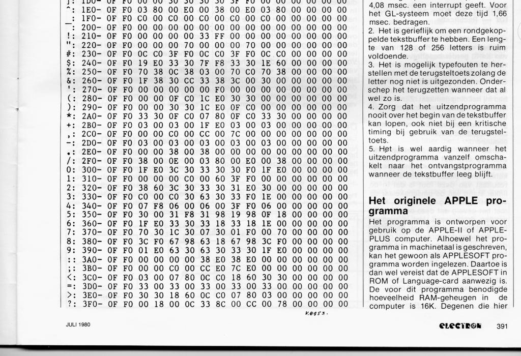
8 Seite 4 von 7 4. Additionally. I have put in a black cursor which moves in front of the printed text. so that one can see at once where the new text is being printed. This means another doubling of the number of plot points. 5. It is probably possible to plot routine which works with different addresses. 6. Changes to tbe wait loop can be made by pressing one of the keys. This key lengthens or shortens the wait time in small increments. TRANSMIT PROGRAM It is fairly easy to program a com puter to send HELL characters, basically tbe same routine as for a morse code generator but with different timing and character set. The heart of the sending program is a look-up table. HELL characters have a different appearance to the computer's own character set, so a conversion table has been put into the memory, comparable to the encoder drum of the original apparatus. The contents of the table is shown in diagram (3) in hexadecimal form. Two immediately adjacent bytes combine to form one picture line. The bits must be read with the highest value (MSB) first, which gives a picture line composed of 14 bits. The two lowest bits of the second byte are not used. A HELL character is composed of 7 picture lines, of which 5 are used for the actual letter and 2 for the space between the letters. For the Army Hell Printer, columns 2 to 15 are used. Columns 2 to 11 contain character information, and columns 12 to 15 contain the space between the letters. All the characters are arranged in the ASCII sequence. The letter E on the sixth row now consists of 3ff0, When converted to ones and zeroes, this becomes , , , , There is a start pulse in columns 0 and 1. These are used in the GL stop-start system. This system only uses columns 0 to 13. By this means. the same character generator can be used for two different HELL systems. TEXT BUFFER
9 Seite 5 von 7 When text is transmitted with an Army HELL printer, the keys must be pressed in at fixed intervals determined by the rotation speed of the encoder drum. This takes a bit of practice to get used to. However in a microcomputer we can put in a text buffer. Then any operator can type text in the text buffer at his (her) own speed whilst the sending program transmits the text in the text buffer with perfect regularity. It is even easier for the operator if the contents of the text buffer can be shown on the monitor screen (split screen operation). TEXT BUFFER PROGRAM CONSTRUCTION 1. Look to see if there is a character in the text buffer. If not, use a space. If yes. take a letter out of the buffer. 2. Take the first byte from the conversion table. 3. Send out 8 bits with the MSB first. 4. Take the next byte out of the conversion table. 5. Send out 6 bits with the MSB first. 6. Look to see if any key has been pressed. 7. Take the next byte out of the conversion table. 8. Go six times to Go to 1. Some notes; 1. Make sure that there is an interval of 4.08 milliseconds between sending out each bit, this can be done by a waiting loop just in front of the sending out instruction, controlled by the preceeding program. One could also use a programmable counter timer (not in the APPLE) which produces an interrupt every 4.O8 milliseconds. For the GL system this time should be 1.66 millisecoads. 2. It is very convenient to have a FIFO text buffer. Alength of 128 or 256 is more than sufficient. 3. It is possible to correct typing errors by using the left arrow (<) if the character has not been sent. This does not of course work if the character has been sent. 4. Make sure that the sending routine can not go further than the start of the text buffer, not even if the timing is critical and the left arrow (<) is used.
10 Seite 6 von 7 5. It is a nice touch if the sending program automatically switches over to receive if the text buffer empty. THE ORIGINAL APPLE PROGRAM The program was developed for use with an APPLE-II or APPLE plus computer. It is written in machine code but can be fed in as Applesoft. However an Applesoft ROM or language board must then be installed in the apparatus. The quantity of memory needed is 16k RAM. Any seriously interested person is welcome to contact the translator. OTHER COMPUTERS It is possible that no other com puters have yet been programmed to emulate a HELL printer. Perhaps after reading this article there will be a few people who want to have a go at it. The hi-res graphics on the APPLE are not strictly necessary. The only difference is that the text would be larger. A Spectrum would give five strips, which is perfectly sufficient. One could then try to do some sort of bulletin board, which the HELL printer is very suitable for. Hell printing is a very pleasant branch of our hobby, which has many unexplored possibilities. If you succeed with a program, pleplease let the author or translator know so that others may enjoy the fruits of your labours. HELL TRANSMISSIONS It sounds not unlike an East European milltary station which often intrudes on 4O metres, but identifications are normally given in CW to advise other Amateurs that these are in fact Amateur stations on the air. There is a regular weekly European Hell net. Contests are arranged every year, with both short wave and VHF sections.
11 Seite 7 von 7 References 1. REFLECTIES 1979, Technical reflections over ideas and new designs in Elektron, the Journal of the Dutch Radio Society (VER0N) 2. Electron June 1977, Hans Evers DJ0SA 3. Hellscreiber, what it is and how it works. Radio Communication April 1981, S.A.G. Cook G5XB 4. Hellskrift, Historisk Återblick, QTC 9:l980, Karl-Gustav Strid SM6FJB 5. Faltfjarrskrivare T.typ 58, System Siemens-Hell, SARTG News No 36, Karl-Gustav Strid SM6FJB 6. Hell op de twee-meter band in alle modes. Electron, H.G. Dikker PE0HGD 7. The Hellschreiber, a rediscovery, Ham Radio Dec 1979, Hans Evers (DJ0SA) This article has been prepared for the net by LA9IHA.
Translated and adapted by Andrew Lovell G6BZS, SM6MOJ
 Seite 1 von 7 COMPUTERS MICRO-HELL From Electron, July 1980 By K. H. J. Roberts, PA0KLS, VALKENWAARD Translated and adapted by Andrew Lovell G6BZS, SM6MOJ Click here for the initial page on HELL schreibers
The BAT WAVE ANALYZER project
 The BAT WAVE ANALYZER project Conditions of Use The Bat Wave Analyzer program is free for personal use and can be redistributed provided it is not changed in any way, and no fee is requested. The Bat Wave
Chapter 3 Digital Data
 Chapter 3 Digital Data So far, chapters 1 and 2 have dealt with audio and video signals, respectively. Both of these have dealt with analog waveforms. In this chapter, we will discuss digital signals in
Hellschreiber Modes - Technical Specifications
 Hellschreiber Modes - Technical Specifications Contents 1. Preamble 2. Feld-Hell Definition Coding Timing Modulation Demodulation 3. C/MT-Hell Definition Coding Timing Modulation Demodulation 4. S/MT-Hell
FPGA Laboratory Assignment 4. Due Date: 06/11/2012
 FPGA Laboratory Assignment 4 Due Date: 06/11/2012 Aim The purpose of this lab is to help you understanding the fundamentals of designing and testing memory-based processing systems. In this lab, you will
Workshop 4 (A): Telemetry and Data Acquisition
: Telemetry and Data Acquisition") Workshop 4 (A): Telemetry and Data Acquisition Mahidol University June 13, 2008 Paul Evenson University of Delaware Bartol Research Institute 1 Workshop Series Idea Introduce students to technical aspects
Workshop 4 (A): Telemetry and Data Acquisition Mahidol University June 13, 2008 Paul Evenson University of Delaware Bartol Research Institute 1 Workshop Series Idea Introduce students to technical aspects
General Certificate of Education Advanced Subsidiary Examination June Problem Solving, Programming, Data Representation and Practical Exercise
 General Certificate of Education Advanced Subsidiary Examination June 2012 Computing COMP1 Unit 1 Problem Solving, Programming, Data Representation and Practical Exercise Friday 25 May 2012 9.00 am to
SSTV Transmission Methodology
 SSTV Transmission Methodology Slow Scan TV (SSTV) is a video mode which uses analog frequency modulation. Every different brightness in the image is assigned a different audio frequency. The modulating
FPGA 设计实例 基于 FPGA 的图形液晶显示面板应用. Graphic LCD panel. FPGAs make great video controllers and can easily control graphic LCD panels.
 FPGA 设计实例 基于 FPGA 的图形液晶显示面板应用 Graphic LCD panel FPGAs make great video controllers and can easily control graphic LCD panels. This project is split in 4 parts: 1. Introduction 2. Video generator 3. Graphics
INTERLACE CHARACTER EDITOR (ICE) Programmed by Bobby Clark. Version 1.0 for the ABBUC Software Contest 2011
 Programmed by Bobby Clark. Version 1.0 for the ABBUC Software Contest 2011") INTERLACE CHARACTER EDITOR (ICE) Programmed by Bobby Clark Version 1.0 for the ABBUC Software Contest 2011 INTRODUCTION Interlace Character Editor (ICE) is a collection of three font editors written in
INTERLACE CHARACTER EDITOR (ICE) Programmed by Bobby Clark Version 1.0 for the ABBUC Software Contest 2011 INTRODUCTION Interlace Character Editor (ICE) is a collection of three font editors written in
UNIT V 8051 Microcontroller based Systems Design
 UNIT V 8051 Microcontroller based Systems Design INTERFACING TO ALPHANUMERIC DISPLAYS Many microprocessor-controlled instruments and machines need to display letters of the alphabet and numbers. Light
Training Document for Comprehensive Automation Solutions Totally Integrated Automation (T I A)
") Training Document for Comprehensive Automation Solutions Totally Integrated Automation (T I A) MODULE T I A Training Document Page 1 of 66 Module This document has been written by Siemens AG for training
Training Document for Comprehensive Automation Solutions Totally Integrated Automation (T I A) MODULE T I A Training Document Page 1 of 66 Module This document has been written by Siemens AG for training
PART FOUR. Polyalphabetic Substitution Systems PERIODIC POLYALPHABETIC SUBSTITUTION SYSTEMS
 PART FOUR Polyalphabetic Substitution Systems PERIODIC POLYALPHABETIC SUBSTITUTION SYSTEMS CHAPTER 8 Section I Characteristics of Periodic Systems 8-1. Types of Polyalphabetic Systems All the substitution
Laboratory Exercise 4
 Laboratory Exercise 4 Polling and Interrupts The purpose of this exercise is to learn how to send and receive data to/from I/O devices. There are two methods used to indicate whether or not data can be
Programmer s Reference
 Programmer s Reference 1 Introduction This manual describes Launchpad s MIDI communication format. This is all the proprietary information you need to be able to write patches and applications that are
TV Synchronism Generation with PIC Microcontroller
 TV Synchronism Generation with PIC Microcontroller With the widespread conversion of the TV transmission and coding standards, from the early analog (NTSC, PAL, SECAM) systems to the modern digital formats
CAP240 First semester 1430/1431. Sheet 4
 King Saud University College of Computer and Information Sciences Department of Information Technology CAP240 First semester 1430/1431 Sheet 4 Multiple choice Questions 1-Unipolar, bipolar, and polar encoding
VEHICLE TELEMETRY DATA IN THE VERTICAL BLANKING INTERVAL
 VEHICLE TELEMETRY DATA IN THE VERTICAL BLANKING INTERVAL Thomas J. Ryan Senior Engineer Instrumentation Development Branch BDM Corp. P.O. Box 416 Ft. Ord, Ca., 93941 ABSTRACT This paper describes how three
TV Character Generator
 TV Character Generator TV CHARACTER GENERATOR There are many ways to show the results of a microcontroller process in a visual manner, ranging from very simple and cheap, such as lighting an LED, to much
The W8TEE/K2ZIA Antenna Analyzer. Dr. Jack Purdum, W8TEE Farrukh Zia, K2ZIA
 The W8TEE/K2ZIA Antenna Analyzer by Dr. Jack Purdum, W8TEE Farrukh Zia, K2ZIA Introduction The W8Antenna TEE/K2ZIA Analyzer (AA) is a general purpose antenna analyzer than can measure resonance for a given
Digital Logic Design: An Overview & Number Systems
 Digital Logic Design: An Overview & Number Systems Analogue versus Digital Most of the quantities in nature that can be measured are continuous. Examples include Intensity of light during the day: The
Copyright 2008 Society of Manufacturing Engineers. FUNDAMENTALS OF TOOL DESIGN Progressive Die Design
 FUNDAMENTALS OF TOOL DESIGN Progressive Die Design SCENE 1. PD06A, tape FTD29, 09:14:22:00-09:14:48:00 pan, progressive die operation PROGRESSIVE DIES PERFORM A SERIES OF FUNDAMENTAL CUTTING AND FORMING
Elements of a Television System
 1 Elements of a Television System 1 Elements of a Television System The fundamental aim of a television system is to extend the sense of sight beyond its natural limits, along with the sound associated
Pivoting Object Tracking System
 Pivoting Object Tracking System [CSEE 4840 Project Design - March 2009] Damian Ancukiewicz Applied Physics and Applied Mathematics Department da2260@columbia.edu Jinglin Shen Electrical Engineering Department
The perforator machine below shows in the front, the three keys. The left is for dots, the centre is for space and the right is for dashes.
 MACHINE TELEGRAPHY SYSTEMS USED IN AUSTRALIA By Ron McMullen former Telegraphist, Telegraph Supervisor, Instructor, Senior Postal Clerk and Postmaster in the former Australian P.M.G. Department. The Wheatstone
Scans and encodes up to a 64-key keyboard. DB 1 DB 2 DB 3 DB 4 DB 5 DB 6 DB 7 V SS. display information.
 Programmable Keyboard/Display Interface - 8279 A programmable keyboard and display interfacing chip. Scans and encodes up to a 64-key keyboard. Controls up to a 16-digit numerical display. Keyboard has
DLA-HD350 / DLA-HD750 DLA-HD550 / DLA-HD950 DLA-HD990 DLA-RS10 / DLA-RS20 DLA-RS15 / DLA-RS25 DLA-RS35. RS-232C and Infrared Remote Control Guide
 JVC D-ILA Projector DLA-HD350 / DLA-HD750 DLA-HD550 / DLA-HD950 DLA-HD990 DLA-RS10 / DLA-RS20 DLA-RS15 / DLA-RS25 DLA-RS35 RS-232C and Infrared Remote Control Guide Version 1.1 Contents Introduction...2
Counter/timer 2 of the 83C552 microcontroller
 INTODUCTION TO THE 83C552 The 83C552 is an 80C51 derivative with several extended features: 8k OM, 256 bytes AM, 10-bit A/D converter, two PWM channels, two serial I/O channels, six 8-bit I/O ports, and
Chapter 9 MSI Logic Circuits
 Chapter 9 MSI Logic Circuits Chapter 9 Objectives Selected areas covered in this chapter: Analyzing/using decoders & encoders in circuits. Advantages and disadvantages of LEDs and LCDs. Observation/analysis
PCM ENCODING PREPARATION... 2 PCM the PCM ENCODER module... 4
 PCM ENCODING PREPARATION... 2 PCM... 2 PCM encoding... 2 the PCM ENCODER module... 4 front panel features... 4 the TIMS PCM time frame... 5 pre-calculations... 5 EXPERIMENT... 5 patching up... 6 quantizing
8 X 8 KEYBOARD INTERFACE (WITHOUT INTERRUPT SIGNAL)
") UNIT 4 REFERENCE 1 8 X 8 KEYBOARD INTERFACE (WITHOUT INTERRUPT SIGNAL) Statement: Interface an 8 x 8 matrix keyboard to 8085 through 8279 in 2-key lockout mode and write an assembly language program to
UNIT 4 REFERENCE 1 8 X 8 KEYBOARD INTERFACE (WITHOUT INTERRUPT SIGNAL) Statement: Interface an 8 x 8 matrix keyboard to 8085 through 8279 in 2-key lockout mode and write an assembly language program to
The PK Antenna Analyzer
 The PK Antenna Analyzer Figure 1. The PK Antenna Analyzer, PKAA. The PK antenna analyzer (PKAA) is a low cost, full-featured instrument with many unique features: VSWR measurements covering all amateur
decodes it along with the normal intensity signal, to determine how to modulate the three colour beams.
 Television Television as we know it today has hardly changed much since the 1950 s. Of course there have been improvements in stereo sound and closed captioning and better receivers for example but compared
METHOD, COMPUTER PROGRAM AND APPARATUS FOR DETERMINING MOTION INFORMATION FIELD OF THE INVENTION
 1 METHOD, COMPUTER PROGRAM AND APPARATUS FOR DETERMINING MOTION INFORMATION FIELD OF THE INVENTION The present invention relates to motion 5tracking. More particularly, the present invention relates to
Advanced Synchronization Techniques for Data Acquisition
 Application Note 128 Advanced Synchronization Techniques for Data Acquisition Introduction Brad Turpin Many of today s instrumentation solutions require sophisticated timing of a variety of I/O functions
IMS B007 A transputer based graphics board
 IMS B007 A transputer based graphics board INMOS Technical Note 12 Ray McConnell April 1987 72-TCH-012-01 You may not: 1. Modify the Materials or use them for any commercial purpose, or any public display,
Digital Blocks Semiconductor IP
 Digital Blocks Semiconductor IP General Description The Digital Blocks core is a full function equivalent to the Motorola MC6845 device. The interfaces a microprocessor to a raster-scan CRT display. The
Spatio-temporal inaccuracies of video-based ultrasound images of the tongue
 Spatio-temporal inaccuracies of video-based ultrasound images of the tongue Alan A. Wrench 1*, James M. Scobbie * 1 Articulate Instruments Ltd - Queen Margaret Campus, 36 Clerwood Terrace, Edinburgh EH12
Hitachi Europe Ltd. ISSUE : app084/1.0 APPLICATION NOTE DATE : 28/04/99
 APPLICATION NOTE DATE : 28/04/99 Design Considerations when using a Hitachi Medium Resolution Dot Matrix Graphics LCD Introduction Hitachi produces a wide range of monochrome medium resolution dot matrix
(12) Publication of Unexamined Patent Application (A)
 Publication of Unexamined Patent Application (A)") Case #: JP H9-102827A (19) JAPANESE PATENT OFFICE (51) Int. Cl. 6 H04 M 11/00 G11B 15/02 H04Q 9/00 9/02 (12) Publication of Unexamined Patent Application (A) Identification Symbol 301 346 301 311 JPO File
Case #: JP H9-102827A (19) JAPANESE PATENT OFFICE (51) Int. Cl. 6 H04 M 11/00 G11B 15/02 H04Q 9/00 9/02 (12) Publication of Unexamined Patent Application (A) Identification Symbol 301 346 301 311 JPO File
THE DIGITAL DELAY ADVANTAGE A guide to using Digital Delays. Synchronize loudspeakers Eliminate comb filter distortion Align acoustic image.
 THE DIGITAL DELAY ADVANTAGE A guide to using Digital Delays Synchronize loudspeakers Eliminate comb filter distortion Align acoustic image Contents THE DIGITAL DELAY ADVANTAGE...1 - Why Digital Delays?...
SPI Serial Communication and Nokia 5110 LCD Screen
 8 SPI Serial Communication and Nokia 5110 LCD Screen 8.1 Objectives: Many devices use Serial Communication to communicate with each other. The advantage of serial communication is that it uses relatively
For an alphabet, we can make do with just { s, 0, 1 }, in which for typographic simplicity, s stands for the blank space.
 Problem 1 (A&B 1.1): =================== We get to specify a few things here that are left unstated to begin with. I assume that numbers refers to nonnegative integers. I assume that the input is guaranteed
MIDI Time Code hours minutes seconds frames 247
 MIDI Time Code In the video or film production process, it is common to have the various audio tracks (dialog, effects, music) on individual players that are electronically synchronized with the picture.
Lab experience 1: Introduction to LabView
 Lab experience 1: Introduction to LabView LabView is software for the real-time acquisition, processing and visualization of measured data. A LabView program is called a Virtual Instrument (VI) because
DELTA MODULATION AND DPCM CODING OF COLOR SIGNALS
 DELTA MODULATION AND DPCM CODING OF COLOR SIGNALS Item Type text; Proceedings Authors Habibi, A. Publisher International Foundation for Telemetering Journal International Telemetering Conference Proceedings
MODULE 3. Combinational & Sequential logic
 MODULE 3 Combinational & Sequential logic Combinational Logic Introduction Logic circuit may be classified into two categories. Combinational logic circuits 2. Sequential logic circuits A combinational
Communication Lab. Assignment On. Bi-Phase Code and Integrate-and-Dump (DC 7) MSc Telecommunications and Computer Networks Engineering
 MSc Telecommunications and Computer Networks Engineering") Faculty of Engineering, Science and the Built Environment Department of Electrical, Computer and Communications Engineering Communication Lab Assignment On Bi-Phase Code and Integrate-and-Dump (DC 7) MSc
Faculty of Engineering, Science and the Built Environment Department of Electrical, Computer and Communications Engineering Communication Lab Assignment On Bi-Phase Code and Integrate-and-Dump (DC 7) MSc
Nintendo. January 21, 2004 Good Emulators I will place links to all of these emulators on the webpage. Mac OSX The latest version of RockNES
 98-026 Nintendo. January 21, 2004 Good Emulators I will place links to all of these emulators on the webpage. Mac OSX The latest version of RockNES (2.5.1) has various problems under OSX 1.03 Pather. You
COMPOSITE VIDEO LUMINANCE METER MODEL VLM-40 LUMINANCE MODEL VLM-40 NTSC TECHNICAL INSTRUCTION MANUAL
 COMPOSITE VIDEO METER MODEL VLM- COMPOSITE VIDEO METER MODEL VLM- NTSC TECHNICAL INSTRUCTION MANUAL VLM- NTSC TECHNICAL INSTRUCTION MANUAL INTRODUCTION EASY-TO-USE VIDEO LEVEL METER... SIMULTANEOUS DISPLAY...
Spinner- an exercise in UI development. Spin a record Clicking
 - an exercise in UI development. I was asked to make an on-screen version of a rotating disk for scratching effects. Here's what I came up with, with some explanation of the process I went through in designing
for Television ---- Formatting AES/EBU Audio and Auxiliary Data into Digital Video Ancillary Data Space
 SMPTE STANDARD ANSI/SMPTE 272M-1994 for Television ---- Formatting AES/EBU Audio and Auxiliary Data into Digital Video Ancillary Data Space 1 Scope 1.1 This standard defines the mapping of AES digital
Lab Determining the Screen Resolution of a Computer
 Lab 1.3.3 Determining the Screen Resolution of a Computer Objectives Determine the current screen resolution of a PC monitor. Determine the maximum resolution for the highest color quality. Calculate the
MUSIC TRANSCRIBER. Overall System Description. Alessandro Yamhure 11/04/2005
 Roberto Carli 6.111 Project Proposal MUSIC TRANSCRIBER Overall System Description The aim of this digital system is to convert music played into the correct sheet music. We are basically implementing a
ANTENNAS, WAVE PROPAGATION &TV ENGG. Lecture : TV working
 ANTENNAS, WAVE PROPAGATION &TV ENGG Lecture : TV working Topics to be covered Television working How Television Works? A Simplified Viewpoint?? From Studio to Viewer Television content is developed in
Part 1: Introduction to Computer Graphics
 Part 1: Introduction to Computer Graphics 1. Define computer graphics? The branch of science and technology concerned with methods and techniques for converting data to or from visual presentation using
Zero Crossover Dynamic Power Synchronization Technology Overview
 Technical Note Zero Crossover Dynamic Power Synchronization Technology Overview Background Engineers have long recognized the power benefits of zero crossover (Figure 1) over phase angle (Figure 2) power
Liquid Mix Plug-in. User Guide FA
 Liquid Mix Plug-in User Guide FA0000-01 1 1. COMPRESSOR SECTION... 3 INPUT LEVEL...3 COMPRESSOR EMULATION SELECT...3 COMPRESSOR ON...3 THRESHOLD...3 RATIO...4 COMPRESSOR GRAPH...4 GAIN REDUCTION METER...5
4. ANALOG TV SIGNALS MEASUREMENT
 Goals of measurement 4. ANALOG TV SIGNALS MEASUREMENT 1) Measure the amplitudes of spectral components in the spectrum of frequency modulated signal of Δf = 50 khz and f mod = 10 khz (relatively to unmodulated
Step 1 - shaft decoder to generate clockwise/anticlockwise signals
 Workshop Two Shaft Position Encoder Introduction Some industrial automation applications require control systems which know the rotational position of a shaft. Similar devices are also used for digital
High Performance Raster Scan Displays
 High Performance Raster Scan Displays Item Type text; Proceedings Authors Fowler, Jon F. Publisher International Foundation for Telemetering Journal International Telemetering Conference Proceedings Rights
DESIGN AND DEVELOPMENT OF A MICROCONTROLLER BASED PORTABLE ECG MONITOR
 Bangladesh Journal of Medical Physics Vol. 4, No.1, 2011 DESIGN AND DEVELOPMENT OF A MICROCONTROLLER BASED PORTABLE ECG MONITOR Nahian Rahman 1, A K M Bodiuzzaman, A Raihan Abir, K Siddique-e Rabbani Department
HEAD. HEAD VISOR (Code 7500ff) Overview. Features. System for online localization of sound sources in real time
 Overview. Features. System for online localization of sound sources in real time") HEAD Ebertstraße 30a 52134 Herzogenrath Tel.: +49 2407 577-0 Fax: +49 2407 577-99 email: info@head-acoustics.de Web: www.head-acoustics.de Data Datenblatt Sheet HEAD VISOR (Code 7500ff) System for online
HEAD Ebertstraße 30a 52134 Herzogenrath Tel.: +49 2407 577-0 Fax: +49 2407 577-99 email: info@head-acoustics.de Web: www.head-acoustics.de Data Datenblatt Sheet HEAD VISOR (Code 7500ff) System for online
News from Rohde&Schwarz Number 195 (2008/I)
") BROADCASTING TV analyzers 45120-2 48 R&S ETL TV Analyzer The all-purpose instrument for all major digital and analog TV standards Transmitter production, installation, and service require measuring equipment
BROADCASTING TV analyzers 45120-2 48 R&S ETL TV Analyzer The all-purpose instrument for all major digital and analog TV standards Transmitter production, installation, and service require measuring equipment
LESSON 1 PITCH NOTATION AND INTERVALS
 FUNDAMENTALS I 1 Fundamentals I UNIT-I LESSON 1 PITCH NOTATION AND INTERVALS Sounds that we perceive as being musical have four basic elements; pitch, loudness, timbre, and duration. Pitch is the relative
PCIe: EYE DIAGRAM ANALYSIS IN HYPERLYNX
 PCIe: EYE DIAGRAM ANALYSIS IN HYPERLYNX w w w. m e n t o r. c o m PCIe: Eye Diagram Analysis in HyperLynx PCI Express Tutorial This PCI Express tutorial will walk you through time-domain eye diagram analysis
Sampling Worksheet: Rolling Down the River
 Sampling Worksheet: Rolling Down the River Name: Part I A farmer has just cleared a new field for corn. It is a unique plot of land in that a river runs along one side. The corn looks good in some areas
Decade Counters Mod-5 counter: Decade Counter:
 Decade Counters We can design a decade counter using cascade of mod-5 and mod-2 counters. Mod-2 counter is just a single flip-flop with the two stable states as 0 and 1. Mod-5 counter: A typical mod-5
Student Guide for SOLO-TUNED HARMONICA (Part II Chromatic)
") Student Guide for SOLO-TUNED HARMONICA (Part II Chromatic) Presented by The Gateway Harmonica Club, Inc. St. Louis, Missouri To participate in the course Solo-Tuned Harmonica (Part II Chromatic), the student
Student Guide for SOLO-TUNED HARMONICA (Part II Chromatic) Presented by The Gateway Harmonica Club, Inc. St. Louis, Missouri To participate in the course Solo-Tuned Harmonica (Part II Chromatic), the student
Manual of Operation for WaveNode Model WN-2m. Revision 1.0
 Manual of Operation for WaveNode Model WN-2m. Revision 1.0 TABLE OF CONTENTS 1. Description of Operation 2. Features 3. Installation and Checkout 4. Graphical Menus 5. Information for Software Expansion
E X P E R I M E N T 1
 E X P E R I M E N T 1 Getting to Know Data Studio Produced by the Physics Staff at Collin College Copyright Collin College Physics Department. All Rights Reserved. University Physics, Exp 1: Getting to
CS302 - Digital Logic & Design
 AN OVERVIEW & NUMBER SYSTEMS Lesson No. 01 Analogue versus Digital Most of the quantities in nature that can be measured are continuous. Examples include Intensity of light during the da y: The intensity
DT9834 Series High-Performance Multifunction USB Data Acquisition Modules
 DT9834 Series High-Performance Multifunction USB Data Acquisition Modules DT9834 Series High Performance, Multifunction USB DAQ Key Features: Simultaneous subsystem operation on up to 32 analog input channels,
STANDARDS CONVERSION OF A VIDEOPHONE SIGNAL WITH 313 LINES INTO A TV SIGNAL WITH.625 LINES
 R871 Philips Res. Repts 29, 413-428, 1974 STANDARDS CONVERSION OF A VIDEOPHONE SIGNAL WITH 313 LINES INTO A TV SIGNAL WITH.625 LINES by M. C. W. van BUUL and L. J. van de POLDER Abstract A description
Setting Up the Warp System File: Warp Theater Set-up.doc 25 MAY 04
 Setting Up the Warp System File: Warp Theater Set-up.doc 25 MAY 04 Initial Assumptions: Theater geometry has been calculated and the screens have been marked with fiducial points that represent the limits
RECOMMENDATION ITU-R BT (Questions ITU-R 25/11, ITU-R 60/11 and ITU-R 61/11)
") Rec. ITU-R BT.61-4 1 SECTION 11B: DIGITAL TELEVISION RECOMMENDATION ITU-R BT.61-4 Rec. ITU-R BT.61-4 ENCODING PARAMETERS OF DIGITAL TELEVISION FOR STUDIOS (Questions ITU-R 25/11, ITU-R 6/11 and ITU-R 61/11)
Rec. ITU-R BT.61-4 1 SECTION 11B: DIGITAL TELEVISION RECOMMENDATION ITU-R BT.61-4 Rec. ITU-R BT.61-4 ENCODING PARAMETERS OF DIGITAL TELEVISION FOR STUDIOS (Questions ITU-R 25/11, ITU-R 6/11 and ITU-R 61/11)
Fingerprint Verification System
 Fingerprint Verification System Cheryl Texin Bashira Chowdhury 6.111 Final Project Spring 2006 Abstract This report details the design and implementation of a fingerprint verification system. The system
Design and Implementation of Timer, GPIO, and 7-segment Peripherals
 Design and Implementation of Timer, GPIO, and 7-segment Peripherals 1 Module Overview Learn about timers, GPIO and 7-segment display; Design and implement an AHB timer, a GPIO peripheral, and a 7-segment
Table of Contents Introduction
 Page 1/9 Waveforms 2015 tutorial 3-Jan-18 Table of Contents Introduction Introduction to DAD/NAD and Waveforms 2015... 2 Digital Functions Static I/O... 2 LEDs... 2 Buttons... 2 Switches... 2 Pattern Generator...
Sequential Logic Notes
 Sequential Logic Notes Andrew H. Fagg igital logic circuits composed of components such as AN, OR and NOT gates and that do not contain loops are what we refer to as stateless. In other words, the output
Magnetic tape storage sgstem for m rπr
 Magnetic tape storage sgstem for m rπr Contents Page 1.0 GENERAL 3 2.0 BASIC PRINCIPLES 3 3.0 OPERATION. 4 4.0 READING AND WRITING. 5 5.0 PARITY CHECKING. 6 6.0 CONSTRUCTION 6 7.0 OPERATING SPEEDS 6 1
The Lincoln TX-2 Input-Output System*
 156 1957 WESTERN COMPUTER PROCEEDINGS The Lincoln TX-2 Input-Output System*, JAMES w. FORGIEt INTRODUCTION THE input-output system of the Lincoln TX-2 computer contains a variety of input-output devices
NAPIER. University School of Engineering. Advanced Communication Systems Module: SE Television Broadcast Signal.
 NAPIER. University School of Engineering Television Broadcast Signal. luminance colour channel channel distance sound signal By Klaus Jørgensen Napier No. 04007824 Teacher Ian Mackenzie Abstract Klaus
800 Displaying Series Flowmeter
 TECHNICAL PRODUCT INSTRUCTION SHEET 800 Displaying Series Flowmeter OVERVIEW The principle of operation is very simple. A jet of liquid is directed at a free running Pelton wheel turbine in a specially
Clarification for 3G Coverage Obligation Verification Data
 Clarification for 3G Coverage Obligation Verification Data Publication date: 7 June 2013 Contents Section Page 1 Introduction 1 2 Data Processing 3 3 Data Formatting 7 4 Data Validation 9 Annex Page 1
Obsolete Product(s) - Obsolete Product(s)
 - Obsolete Product(s)") AN1841 APPLICATION NOTE Closed Caption and XDS Software 1 INTRODUCTION This document describes the Closed Caption and extended Data Service (XDS) extraction software module available for the ST92x196 family.
AN1841 APPLICATION NOTE Closed Caption and XDS Software 1 INTRODUCTION This document describes the Closed Caption and extended Data Service (XDS) extraction software module available for the ST92x196 family.
Kramer Electronics, Ltd. USER MANUAL. Models: VS-162AV, 16x16 Audio-Video Matrix Switcher VS-162AVRCA, 16x16 Audio-Video Matrix Switcher
 Kramer Electronics, Ltd. USER MANUAL Models: VS-162AV, 16x16 Audio-Video Matrix Switcher VS-162AVRCA, 16x16 Audio-Video Matrix Switcher Contents Contents 1 Introduction 1 2 Getting Started 1 3 Overview
Team Members: Erik Stegman Kevin Hoffman
 EEL 4924 Electrical Engineering Design (Senior Design) Preliminary Design Report 24 January 2011 Project Name: Future of Football Team Name: Future of Football Team Members: Erik Stegman Kevin Hoffman
 1. Keyboard and Panel Switch Scanning DX7 CIRCUIT DESCRIPTION The 4 bits BO ~ B3 from the sub-cpu (6805S) are input to the decoder (40H138). The decoder output is sent to the keyboard transfer contacts
The Micropython Microcontroller
 Please do not remove this manual from the lab. It is available via Canvas Electronics Aims of this experiment Explore the capabilities of a modern microcontroller and some peripheral devices. Understand
Exercise 1-2. Digital Trunk Interface EXERCISE OBJECTIVE
 Exercise 1-2 Digital Trunk Interface EXERCISE OBJECTIVE When you have completed this exercise, you will be able to explain the role of the digital trunk interface in a central office. You will be familiar
BTV Tuesday 21 November 2006
 Test Review Test from last Thursday. Biggest sellers of converters are HD to composite. All of these monitors in the studio are composite.. Identify the only portion of the vertical blanking interval waveform
CSCB58 - Lab 4. Prelab /3 Part I (in-lab) /1 Part II (in-lab) /1 Part III (in-lab) /2 TOTAL /8
 /1 Part II (in-lab) /1 Part III (in-lab) /2 TOTAL /8") CSCB58 - Lab 4 Clocks and Counters Learning Objectives The purpose of this lab is to learn how to create counters and to be able to control when operations occur when the actual clock rate is much faster.
CSCB58 - Lab 4 Clocks and Counters Learning Objectives The purpose of this lab is to learn how to create counters and to be able to control when operations occur when the actual clock rate is much faster.
Linrad On-Screen Controls K1JT
 Linrad On-Screen Controls K1JT Main (Startup) Menu A = Weak signal CW B = Normal CW C = Meteor scatter CW D = SSB E = FM F = AM G = QRSS CW H = TX test I = Soundcard test mode J = Analog hardware tune
Study Guide. Solutions to Selected Exercises. Foundations of Music and Musicianship with CD-ROM. 2nd Edition. David Damschroder
 Study Guide Solutions to Selected Exercises Foundations of Music and Musicianship with CD-ROM 2nd Edition by David Damschroder Solutions to Selected Exercises 1 CHAPTER 1 P1-4 Do exercises a-c. Remember
Ver.mob Quick start
 Ver.mob 14.02.2017 Quick start Contents Introduction... 3 The parameters established by default... 3 The description of configuration H... 5 The top row of buttons... 5 Horizontal graphic bar... 5 A numerical
CHAPTER1: Digital Logic Circuits
 CS224: Computer Organization S.KHABET CHAPTER1: Digital Logic Circuits 1 Sequential Circuits Introduction Composed of a combinational circuit to which the memory elements are connected to form a feedback
Synthesis Technology E102 Quad Temporal Shifter User Guide Version 1.0. Dec
 Synthesis Technology E102 Quad Temporal Shifter User Guide Version 1.0 Dec. 2014 www.synthtech.com/euro/e102 OVERVIEW The Synthesis Technology E102 is a digital implementation of the classic Analog Shift
BER MEASUREMENT IN THE NOISY CHANNEL
 BER MEASUREMENT IN THE NOISY CHANNEL PREPARATION... 2 overview... 2 the basic system... 3 a more detailed description... 4 theoretical predictions... 5 EXPERIMENT... 6 the ERROR COUNTING UTILITIES module...
CHECKPOINT 2.5 FOUR PORT ARBITER AND USER INTERFACE
 1.0 MOTIVATION UNIVERSITY OF CALIFORNIA AT BERKELEY COLLEGE OF ENGINEERING DEPARTMENT OF ELECTRICAL ENGINEERING AND COMPUTER SCIENCE CHECKPOINT 2.5 FOUR PORT ARBITER AND USER INTERFACE Please note that