Installation Device Instruction Guide. Page 1
|
|
|
- Horace Banks
- 6 years ago
- Views:
Transcription


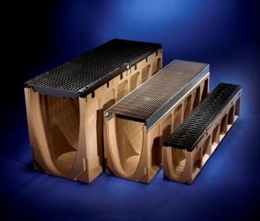
1 Installation Device Instruction Guide Page 1

2 Page 2 Tools required 2 x String lines & pegs. Hammer. Spirit level. 16mm diameter. Lengths to be determined by installer. Bar lengths will vary depending on soil type and height of channel above the trench depth. Number of required 2 per channel + 2 additional for the end channel. 12mm ring spanner. 1.1m length of timber to assist with levelling. Installations device. 1 per channel + 1 additional for the end channel. Read all steps below before starting installation. 2 people minimum are required for the installation of the channels.


3 Page 3 Installation device use Loosen both screws to allow the device to be positioned over the. Fixed side of device Push the adjustable clamp to the outside to allow the channels to be installed. Wedge is fitted during final stage of installation. Step 1 Create the required width template using timber sheet or similarly suitable rigid material. Diagrams can be printed from the ACO website. For ACO s KlassikDrain and PowerDrain System. For ACO s KerbDrain QK200SF and QK200B System.


4 Page 4 Step 2 Set out the top string line for the top edge of the channel run and lay the required channels in sequence along the string line. Also lay out 2 and 1 installation device at the location of each channel joint. Step 3 Set the first channel without using the template to allow for flexibility. Note: The first channel to be set out must be at the outlet/deep end of the run. The fixed side of the installation device must be on the same side of the channel as the string line. Ensure the are adequately pushed into the ground so they do not fall over once the channel is removed and do not sit higher than the top of the channel. Fixed side of device Direction of installation Outlet end of channel

5 Page 5 Step 4 Once the first channel is set, levelled and straightness is achieved, remove the channel and leave the first installation device in place. Remove the second device, but leave the in place. Remove the second installation device from the second row of First installation device on first row of Direction of installation Step 5 Position the template over the second row of. Step 6 Set up the second string line up against the template edge ensuring that both string lines are parallel. The second string line should be just above the ground level to keep the template straight when moving from one channel to the next. The string line should also be on the same side of the channel as the top string line. First stringline for top of channel Second stringline for template edge Second row of


6 Page 6 Step 7 Hammer in the next/third row of reo-bars through the empty template holes. Drive the reinforcing bars into a sufficient depth - not too low to stop the use of the Installation Device. Third row of Second row of Step 8 Remove the template and reposition the template again on the last two that were just installed. Location for fourth row of Third row of Step 9 Re-attach the second installation device to the second row of. Re attach second installation device First installation device


7 Page 7 Step 10 Replace the first channel and ensure the channel is level with the top string line and is level across the width of the channel. If it s too high, tap down the. If it s too low, undo the screws and lift the installation device up. Step 11 Once the first channel has been replaced, DO NOT lock the adjustable side of the clamp with the wedge yet. This allows some movement of the channel when placing the next channel in line. Do not place the channel all the way to the fixed side of the clamp where it will sit in the locked position. This allows for easier installation of channels. Note: Always allow two sets of to be installed before placing channels. This allows the template to be removed and placed into the next position for setting the. Wedge Fixed side Adjustable sliding clamp Step 12 Continue to install devices and repeat process of setting the channels.


8 Page 8 Step 13 After next/fourth channel is set, the first channel can be locked into position using the wedges for the install device. Note, ensure the are installed at least 2 rows ahead prior to installing channels. 7 th row 6 th row 5 th row 4 th row 3 rd row 2 nd row 1 st row Wedge


9 Step 14 Continue to follow steps 7 to 13 until the trench run is complete and ensure all the wedges are in place. Channels are now set up for a single concrete pour operation. The installation device clamps the channels together to brace the channels in place and prevent movement during the concrete pour. Page 9
HQ Electromagnetic Channel Locks
 HQ Electromagnetic Channel Locks Table of Contents Overview... 2 Kit Contents... 2 Tools Required... 5 Installation... 5 Using the HQ Electromagnetic Channel Locks... 10 Troubleshooting... 11 Overview
Installation Guide OvalSox TM Cable
 Installation Guide OvalSox TM Cable Thank you for selecting a DuctSox System. This guide will be helpful for the installation of an OvalSox Cable System. Sections of fabric will be labeled, assembled,
Formulate Designer Series 30 Backwall - Kit 05
 Formulate Designer Series 30 Backwall - Kit 05 Formulate Designer Series 30ft displays have unique stylistic features and shapes, are portable and easy to assemble. The aluminum tube frame features snap-buttons
Formulate Designer Series 30 Backwall - Kit 05
 Formulate Designer Series 30 Backwall - Kit 05 FMLT-DS-30-05 Formulate TM Designer Series 30ft displays have unique stylistic features and shapes, are portable and easy to assemble. The aluminum tube frame
FIST-MB2-S. FIST Medium Box for Cable Splicing Only. 4 Cable installation. 1 Introduction. Contents. 2 General. 5. Fiber routing to individual trays
 FIST-MB2-S I N S T A L L A T I O N I N S T R U C T I O N FIST Medium Box for Cable Splicing Only Contents 1 Introduction 1.1 Product description 2 General 2.1 Tools 2.2 Kit contents 3 Installation and
B.2.CHRONO PLUS SIDE HUNG OPEN IN WINDOWS
 B.2. SIDE HUNG OPEN IN Contents General characteristics................... page B.2.2 Base set n 20510...................... B.2.3 Centre locking set n 30500-850 + 30540-830............... B.2.4 Wedge
Medium Box for Cable Termination
 FIST-MB2-T I N S T A L L A T I O N I N S T R U C T I O N Medium Box for Cable Termination Contents 1 Introduction 1.1 Product description. 2 General 2.1 Tools 2.2 Kit contents 3 Installation and pre assembling
Adapter Selection. Entry Size (Continued) Table E. Multiplication. factors for wire bundles. with Equal Size Wires. This table provides multiplication
 Table E. Multiplication. factors for wire bundles. with Equal Size Wires. This table provides multiplication") Table E. Multiplication Factors for Wire Bundles with Equal Size Wires This table provides multiplication factors for wire bundles of to 6 wires. To determine the approximate diameter of a wire bundle
Table E. Multiplication Factors for Wire Bundles with Equal Size Wires This table provides multiplication factors for wire bundles of to 6 wires. To determine the approximate diameter of a wire bundle
Check what you have received against the component checklist and hardware above.
 SA46S SA46W SA46B SA46PB Component Checklist Installation Instructions SYSTEMA Systema Monitor Arm 460mm HARDWARE Display Mounting Spacers (x4) Display Mounting Screws Arm Assembly VESA monitor head M4
FIST-GCOG2-Dx6. Follow all local safety regulations related to optical fiber plant elements.
 FIST-GCOG2 I N S T A L L A T I O N I N S T R U C T I O N TC-986-IP Rev A, Mar 2017 www.commscope.com FIST-GCOG2-Dx6 Content 1 Introduction 2 General 2.1 Abbreviations 2.2 Kit contents 2.3 Tools 2.4 Accessories
Installation instructions Roxtec RM PE
 Installation instructions Roxtec RM PE Environmental side Environmental side Pipe Cable screen/armor Layers Layers Cable sheath Plastic film Conductive tape Integrated environmental sealing system for
Fiber Optic Splice Closure GPJ Instruction Manual
 Fiber Optic Splice Closure GPJ09-9401 Instruction Manual 1. Brief Introduction GPJ09-9401 type of Fiber Optic Splice Closure is a member in dome series, the main function is to provice direct pass, branch
DLMP Installation Instructions
 DLMP Installation Instructions Tools Needed Posidrive No.3 Screwdriver Large Flat Head Screwdriver 2x 10mm Spanner 1x 13mm Spanner Ø8mm Drill Ø6mm Drill Kit Contents [ ] 1x Tube 2.5M long 17420 [ ] 2 x
Installation instructions Roxtec RM ES
 Installation instructions Roxtec RM ES Environmental side Environmental side Pipe Cable screen/armor Layers Layers Cable sheath Vertical screen Plastic film Conductive tape Integrated environmental sealing
Support Frame STB Technical Instruction Manual
 Support Frame STB Technical Instruction Manual Fig. 2.1: Support frame STB 450 Fig. 2.2: Support frame STB 300 Fig. 2.3: Brace bracket SK 150 Product Characteristics The support frames are mainly used
DLMP-45/45R Installation Instructions
 DLMP-45/45R Installation Instructions Tools Needed Posidrive No.3 Screwdriver Large Flat Head Screwdriver 2x 10mm Spanner 1x 13mm Spanner Ø8mm Drill Ø6mm Drill Kit Contents [ ] 1x Tube 2.5M long 17420
Installation instructions Roxtec RM ES systems
 Safety information Roxtec recommends that all installations are performed without facility operation. Follow national regulations and installation codes. ny action affecting the routed service should be
KEL 183 Cable entry frames
 KEL 183 Cable entry frames Description Type Order.No. Inserts KT PU KT 183 KT large The new version of the split cable entry frame KEL 183 enables the user to route cables and tubes with a diameter up
Installation instructions Roxtec RM PE B
 Installation instructions Roxtec RM PE B Environmental side Termination/ interior side Pipe Cable screen/armor Layers Termination/ interior side Cable sheath Layers Environmental side Plastic film Conductive
Product catalogue 2010
 Product catalogue 2010 welding, cutting and more... www.kemper.eu Extraction systems for the electronic industry Soldering workstations... 153-154 Soldering smoke extraction systems... 155 Accessories
Cable installation guidelines
 The Quality Connection Cable installation guidelines Business Unit Industrial Projects 2 Cable installation guidelines www.leoni-industrial-projects.com GENERAL Installation methods Many different methods
Check what you have received against the component checklist and hardware above.
 SSS SSPW SSW SSPB SSB Component Checklist Installation Instructions SYSTEMA Systema Monitor Spring Arm HARDWARE Display Mounting Spacers (x4) 3/4mm Allen Keys Display Mounting Screws M4 x 14mm (x1) Silver
SP02 Series Tape Feeder. Operator Guide. All rights reserved Revision 1 29 Feb D-E36
 SP02 Series Tape Feeder SP02 Series Tape Feeder Operator Guide All rights reserved Revision 1 29 Feb 08 380D-E36 This page intentionally left blank. SP02 Series Tape Feeders Operator Guide Hover-Davis,
Installation instructions Roxtec RM ES B
 Installation instructions Roxtec RM ES B Environmental side Termination/ interior side Pipe Cable screen/armor Layers Termination/ interior side Cable sheath Layers Environmental side Vertical screen Plastic
DL-AR2 Technical Specifications Universal HDMI Adapter Ring Rev
 DL-AR2 Technical Specifications Universal HDMI Adapter Ring Rev. 130814 The DL-AR2 Digital Adapter Keychain was developed to support the rising proliferation of mobile devices used in presentation systems.
Cold Shrink Straight Joint
 Cold Shrink Straight Joint 3M QS2000E 22 kv Single Core Straight Joint Instruction Sheet All dimensions shown are in mm unless otherwise stated Kits contains components for one single core cable -2-2*
Nava Buffet Assembly Instructions
 Thank you for your purchase. lease follow the instructions below for correct assembly. B dowel x0 x1 bolt x H height adjuster x1 bracket x Q clip x R locking nut x K seal x S F x shelf plugx8 x8 L hinge
F.A.Q. Frequently Asked Questions. Technical Questions
 F.A.Q Frequently Asked Questions Technical Questions How many display panels can I install in my window display? Other than the height limitation of your display window, you have the ability to install
HQ Electromagnetic Channel Locks. For the HQ Infinity
 HQ Electromagnetic Channel Locks For the HQ Infinity Table of Contents Overview... 2 Kit Contents... 2 Tools Required... 4 Installation... 4 Using the HQ Electromagnetic Channel Locks... 9 Troubleshooting...
Step 1. 1x NXT Ultrasonic Sensor
 Start with the build completed in Lesson 3 of the TETRIX Getting Started Guide. Step 1 involves removing an element from the model. This element will be reattached later. Parts to be Removed Step 1 1x
S020 fluorescent tube luminary
 S020 fluorescent tube luminary DESCRIPTION: Fluorescent lamps S020 are suitable above all for uniform lighting of bigger areas. Lamps from the range S020 are manufactured from extruded aluminium profile
INSTRUCTION MANUAL [J] [E] [C] [G] [B] [I] [H] [D] [F] [A] 0 INTRODUCTION 1 RECOMMENDATIONS 2 ACCESSORIES INCLUDED
![INSTRUCTION MANUAL [J] [E] [C] [G] [B] [I] [H] [D] [F] [A] 0 INTRODUCTION 1 RECOMMENDATIONS 2 ACCESSORIES INCLUDED](/thumbs/87/97107658.jpg "INSTRUCTION MANUAL [J] [E] [C] [G] [B] [I] [H] [D] [F] [A] 0 INTRODUCTION 1 RECOMMENDATIONS 2 ACCESSORIES INCLUDED") 0 INTRODUCTION Video Lift is an electro-mechanical device which, once installed in the ceiling, allows vertical movement (ceiling floor ceiling) for loads of up to 19 Kg and with maximum runs of 1 metre
0 INTRODUCTION Video Lift is an electro-mechanical device which, once installed in the ceiling, allows vertical movement (ceiling floor ceiling) for loads of up to 19 Kg and with maximum runs of 1 metre
Formulate Designer Series 20 Backwall - Kit 07
 Formulate Designer Series 20 Backwall - Kit 07 FMLT-DS-20-07 Formulate TM Designer Series 20ft displays have unique stylistic features and shapes, are portable and easy to assemble. The aluminum tube frame
INSTALLATION INSTRUCTIONS
 INSTALLATION INSTRUCTIONS M9700 RGB SERIES Installation should be performed by a qualified electrician in accordance with the National Electrical Code and relevant local codes. Hydrel's M9700 Series of
Installation instructions Roxtec RM BG systems
 Safety information Roxtec recommends that all installations are performed without facility operation. Follow national regulations and installation codes. ny action affecting the routed service should be
The Mambo Twist LED Screen System
 The Mambo Twist LED Screen System The Mambo Twist LED screen system builds on the successful design formula of the Mambo range The Mambo screen system features: 8mm pixel pitch Indoor/outdoor use Light
Automatic Connector MHV Connectors MHV Introduction MHV series connectors Contents Polarized mating interfaces Anti-Rock mating interfaces
 Automatic s 2004 Automatic. All rights reserved. pdf 1.0 3-18-04 Contents Specifications........................... 2 Straight Cable Plugs...................... 3 Right Angle Cable Plugs...................
Litile34 INSTALLATION MANUAL
 Litile34 INSTALLATION MANUAL Seamless Tiled Panel Wall Solution for Large Area Digital Signage Display (1st Edition 3/25/2009) All information is subject to change without notice. Approved by Checked by
Installation instructions Roxtec RM BG B systems
 Safety information Roxtec recommends that all installations are performed without facility operation. Follow national regulations and installation codes. ny action affecting the routed service should be
Nava Entertainment Unit Assembly Instructions
 ava ntertainment nit ssembly nstructions Thank you for your purchase. Please follow the instructions below for correct assembly. B dowel x2 x8 H locking nut x22 Q x32 x10 x10 K bracket x P bolt x22 height
Tripod-1 Manual Rev B
 Tripod-1 Manual 57-6015 Rev B DYACON Tripod-1 Manual 2 Contents NOTICES...3 Copyright 2013 DYACON, Inc...3 Manufacturer...3 Declarations...4 Warranty Information...4 TRIPOD-1 INTRODUCTION...5 Scope...5
KVT Split cable glands
 KVT Split cable glands Description Type Order Inserts KT Thread PU No. small large Thread length KVT is a circular split frame for quick and easy installation of cables or complete cable harnesses. Polyamide
Documentation on all Paxton products can be found on our web site -
 11/05/2012 Ins-30202-US Net2 Entry - Monitor Paxton Technical Support 1.800.672.7298 supportus@paxton-access.com Technical help is available: Monday - Friday from 02:00 AM - 8:00 PM (EST) Documentation
Flat. Compact. Cost-effective. FWS Flat Change System
 Flat. Compact. Cost-effective. FWS Flat Change System Manual tool changing system for small manipulators and grippers, with integrated air and electrical feed-through. Field of Application The changer
MAGNETIC CARD READER DESIGN KIT TECHNICAL SPECIFICATION
 MAGNETIC CARD READER DESIGN KIT TECHNICAL SPECIFICATION Part Number: D99821002 Rev 212 MAY 2017 REGISTERED TO ISO 9001:2008 1710 Apollo Court Seal Beach, CA 90740 Phone: (562) 546-6400 FAX: (562) 546-6301
Caution. Hanging the Screen:
 Installation Instructions for Laminar and Laminar XL Projection Screens Caution 1. Read Instructions through completely before proceeding; keep them for future reference. Follow these instructions carefully.
Cable System Installation Guide
 Overview Cable System Installation Guide 5/19/2008 Our recommended approach for the installation of your Circle Graphics Cable Systems on the panels in your market is to install the fixed hardware (namely
Guía del usuario Español ( 7 10 ) Guide d utilisation Français ( ) Guida per l uso Italiano ( ) Benutzerhandbuch Deutsch ( )
 Guide d utilisation Français ( ) Guida per l uso Italiano ( ) Benutzerhandbuch Deutsch ( )") User Guide English ( 3 6 ) Guía del usuario Español ( 7 10 ) Guide d utilisation Français ( 11 14 ) Guida per l uso Italiano ( 15 18 ) Benutzerhandbuch Deutsch ( 19 22 ) Appendix English ( 23 ) User Guide
User Guide English ( 3 6 ) Guía del usuario Español ( 7 10 ) Guide d utilisation Français ( 11 14 ) Guida per l uso Italiano ( 15 18 ) Benutzerhandbuch Deutsch ( 19 22 ) Appendix English ( 23 ) User Guide
Bionic Elephant Trunk. Assembly Instructions
 Bionic Elephant Trunk Assembly Instructions Equipment and Supplies Required items from the Bionics Kit and/or Materials Pack: 1. Tail fin (small) assembled 2 see Start Here for tail fin assembly instructions
Product information. Front-door station series with video for surface-mount
 Product information Front-door station series with video for surface-mount series VPES series VPDS 2 05/2006 Table of contents Scope of delivery...3 Safety notices...3 General notes on the cabling in TCS
18mm ECAM Cable Entry Port
 18mm ECAM Cable Entry Port Instructions October 2006 1.0 Introduction The 3M 18mm ECAM (External Cable Assembly Module) Cable Entry Port Kit is designed to accept fiber optic cables with external diameters
Formulate Designer Series 10 Backwall - Kit 05
 Formulate Designer Series 10 Backwall - Kit 05 FMLT-DS-10-05 Formulate TM Designer Series 10ft displays have unique stylistic features and shapes, are portable and easy to assemble. The aluminum tube frame
2178-L/S Series Fiber Optic Splice Case with Gasket
 2178-L/S Series Fiber Optic Splice Case with Gasket Instructions for: 2178-S Splice Case 2178-LS Splice Case 2178-LL Splice Case 2181-LS Cable Addition Kit May 1997 34-7041-9949-5-A 1 Table of Contents
Structural Plate Design Guide. 5 th Edition MULTI-PLATE. Aluminum Structural Plate. Aluminum Box Culvert SUPER-SPAN SUPER-PLATE.
 ENGINEERED SOLUTIONS Structural Plate Design Guide 5 th Edition MULTI-PLATE Aluminum Structural Plate SUPER-SPAN SUPER-PLATE BridgeCor Table of Contents Steel and Aluminum Structural Plate design guide.
Bookcheck Model 966. Site Planning Guide
 Bookcheck Model 966 Site Planning Guide 3M Library Systems 3M Center, Building 225-4N-14 St. Paul, Minnesota 55144-1000 Copyright 2002, 3M IPC. All rights reserved. www.3m.com/library 060-A 78-8123-7852-5,
3M Locator Plate N
 M Locator Plate 44-107N Instructions for the assembly of.100 x.100 preassembled socket connectors 1.0 General The M Locator Plate 44-107N is designed to aid in the assembly of the preassembled socket connector
RetractaNet XS. Extractable Solutions for OSP. October 2012
 RetractaNet XS Extractable Solutions for OSP October 2012 OSP Solutions RetractaNet XS Solution Simple concept reduces the need for skilled labor for installation Easy direct buried deployment in soft
Support Frame STB Assembly and Operating Instructions
 Support Frame STB Assembly and Operating Instructions Fig. 2.1 Support frame STB 450 Fig. 2.2 Support frame STB 300 Fig. 2.3 Brace bracket SK 150 Product features The support frames are mainly used for
KIT INSTRUCTIONS. Checkstand Display Mount K039 Issue C
 KIT INSTRUCTIONS Checkstand Display Mount 5968-K039 Issue C The product described in this book is a licensed product of NCR Corporation. NCR is a registered trademark of NCR Corporation. NCR RealPOS is
imac Intel 27" EMC 2546 isight Camera and Microphone Cable Replacement
 imac Intel 27" EMC 2546 isight Camera and Microphone Cable Replacement Replace the isight/microphone cable in your Late 2012 27" imac. Written By: Andrew Optimus Goldberg ifixit CC BY-NC-SA www.ifixit.com
PKK PKK CHARACTERISTICS. Dimensions. Travel. Travel speed. Acceleration. Temperature. Special versions APPLICATION AREAS. PLE max.
 PKK loa d / (kg/m) PKK 10 8 6 4 2 0 0 P KK 1 20 PKK applications 49 PKK dimensions 50 PKK types 52 PKK sizes 54 PKK parts 55 PKK assembly 56 PKK article numbers 62 LOAD DIAGRAM PKK 2 2 0 2 P KK 2 40 PKK
imac Intel 27" EMC 2639 Display Replacement
 imac Intel 27" EMC 2639 Display Replacement Replace the Display in your imac Intel 27" EMC 2639. Rédigé par: Walter Galan ifixit CC BY-NC-SA fr.ifixit.com Page 1 de 16 INTRODUCTION Removing the display
Growmaster Assembly Instructions
 Growmaster ssembly Instructions Item No. Part Sect. Ref. Size mm Quantity Item No. Part Sect. Ref. Size mm Quantity 1001 15 M6 x 12 86x 97x 108x 1067 6 295 16 M6 9 10 113x 1301 7 30 9x 1 13x 5 7 3.5 x
3M Distribution Box (DDB)
") 3M Distribution Box (DDB) Merged Copper and Fiber Pole/Post Mount Enclosure Installation Instructions November 2015 78-0015-2736-1-A 2 November 2015 78-0015-2736-1-A Contents 1.0 General 2.0 Enclosure
3M Distribution Box (DDB) Merged Copper and Fiber Pole/Post Mount Enclosure Installation Instructions November 2015 78-0015-2736-1-A 2 November 2015 78-0015-2736-1-A Contents 1.0 General 2.0 Enclosure
INSTALLATION INSTRUCTIONS MO023A
 INSTALLATION INSTRUCTIONS MO023A Nexans N3S ODF system NEXANS N3S ODF SYSTEM Content Product description Patching frame Splice frame Doors Splice module Patch module Protective cover and label panel Guides
414 P 1. DESCRIPTION AND TECHNICAL SPECIFICATIONS 2. LAY-OUT OF STANDARD SYSTEM INSTALLATION DIMENSIONS. Fig. 1. Fig. A
 1 414 P The 414 P automated system for swing leaf gates is an electromechanical operator which transmits motion to the leaf by a worm-screw system. It is a self-locking automatic system equipped with a
INSTALLATION INSTRUCTIONS
 INSTALLATION INSTRUCTIONS PARTS REQUIRED Parts in the box Single monitor Dual monitor M2 M8 M/Flex + (package contents will depend on configuration ordered) Tools required for installation 6.0 mm Hex Key
Additional Information for Using Sony Wall-Mount Bracket (SU-WL500)
") A-E96-100-12(1) Additional Information for Using Sony Wall-Mount Bracket (SU-WL500) Compatible TV models for this Wall-Mount Bracket information: XBR-84X905/84X900 XBR-65HX957/65HX955/65HX950/55HX957/55HX955/55HX950
A-E96-100-12(1) Additional Information for Using Sony Wall-Mount Bracket (SU-WL500) Compatible TV models for this Wall-Mount Bracket information: XBR-84X905/84X900 XBR-65HX957/65HX955/65HX950/55HX957/55HX955/55HX950
INSTALLATION INSTRUCTIONS
 INSTALLATION INSTRUCTIONS MO036A N-HNS (Building Node Cabinet) N-HNS (BUILDING NODE CABINET) Contents Product description Technical data ODF Splice module Cabling organisation Cable/tube/fibre handling
PRODUCT DESCRIPTION N3S
 PRODUCT DESCRIPTION N3S Nexans N3S ODF system NEXANS N3S ODF SYSTEM Contents Contents Systems description Patching frame Splice frame Patching module (KB 104/109) Splicing module Accessories Page 2 Page
PSC300 Operation Manual
 PSC300 Operation Manual Version 9.10 General information Prior to any attempt to operate this Columbia PSC 300, operator should read and understand the complete operation of the cubing system. It is very
Identification - electrical services
 Identification - electrical services Aesthetic All live phase cable sheathing to be brown coloured and neutral phase cable sheathing to be blue coloured, all labelled L1, L2, L3 & N respectively in accordance
TSUBAKI SEAMLESS LIGHT TYPE V
 WHITE LEDS DESCRIPTION Tsubaki Type V products provide highly flexible lighting strands for smooth and seamlessdirect view applications such as facade lightingand other architectural features. Rigid or
MY-HITE ADJUSTABLE TABLE
 MY-HITE ADJUSTABLE TABLE Corner T Leg Base Model Number : FCNAHBT Please Read Instructions Before Use ASSEMBLY INSTRUCTIONS ALL WORKSTYLES WELCOME Thank you for choosing Friant. We appreciate the trust
Operating instructions Retro-reflective sensor. OJ50xx laser / / 2010
 Operating instructions Retro-reflective sensor OJ50xx laser 70481 / 00 05 / 010 Contents 1 Preliminary note3 1.1 Symbols used 3 Safety instructions 3 4 Installation 4 4.1 Installation of the supplied mounting
The Two Assemblies. Standard Assembly For signs up to 11" wide. Pull flexible lens directly outward with Sucton Cup Tool for lens removal
 System Overview The Two Assemblies The Arris system is comprised of two unique assemblies, each designed to provide maximum cost effectiveness and design flexibility for specific types of signs. With both
THE CABLE TRAY SYSTEM
 C A B L E S A N I T A T I O N C A B L E T R A Y S Y S T E M S THE CABLE TRAY SYSTEM The SILTEC cable tray system is a product, developed for optimum functionality and with focus on simplicity and accessibility,
imac Intel 20" EMC 2133 and 2210 LCD Backlights (CCFL) Replacement
 Replacement") imac Intel 20" EMC 2133 and 2210 LCD Backlights (CCFL) Replacement The CCFL back lights are replaceable. I have pulled mine apart and documented my method. '''NOTE''' This is not for the feint hearted!
imac Intel 20" EMC 2133 and 2210 LCD Backlights (CCFL) Replacement The CCFL back lights are replaceable. I have pulled mine apart and documented my method. '''NOTE''' This is not for the feint hearted!
1.8 METER SERIES 1183 Az/El MOUNT ANTENNA SYSTEM
 REVISION G January 11, 2002 ASSEMBLY MANUAL 1.8 METER SERIES 1183 Az/El MOUNT ANTENNA SYSTEM PRODELIN CORPORATION 1500 Prodelin Drive Newton NC 28658 1.8 METER SERIES 1183 Az/El MOUNT ANTENNA SYSTEM G
7 Day Digital Time Switch
 7 Day Digital Time Switch Model: NTT08 Installation & Operating Instructions 1 1. General Information These instructions should be read carefully and retained for further reference and maintenance. 2.
KUZMA 4POINT TONEARM
 KUZMA 4POINT TONEARM Instruction manual 2008-6 Serial Number:.. 1 KUZMA LTD INSTRUCTION MANUAL FOR 4POINT tonearm The 4POINT tonearm is a very precisely engineered piece of equipment, however, the construction
MP Maker Pro Mk.1. Quick Start Guide
 MP Maker Pro Mk.1 P/N 33013 Quick Start Guide ONLINE SUPPORT Monoprice is pleased to provide free online support. For order related issues, contact the Customer Service department through the Live Chat
IndyGo Facility Upgrades Project 35671EE
 SECTION 260553 IDENTIFICATION FOR ELECTRICAL SYSTEMS PART 1 - GENERAL 1.1 SUMMARY A. Section Includes: 1. Identification for raceways. 2. Identification of power and control cables. 3. Identification for
Sliding Door System Bohle SlideTec optima 60
 Sliding Door System Bohle SlideTec optima 60 The Bohle sliding door hardware system SlideTec optima 60 is a high quality solution for moving glass doors of up to 60kg. Pre-drilling the glass for tempered
SCREEN WINCH SYSTEM INSTALLATION MANUAL FOR SCREENS FROM 300 cm. UP TO 450 cm. of width
 SCREEN WINCH SYSTEM INSTALLATION MANUAL FOR SCREENS FROM 300 cm. UP TO 450 cm. of width Before installing the screen winch system, please read the following instructions carefully: The screen winch system
3M Scotchcast Reenterable Signal and Control Cable Splicing Kits 78-R Series
 3M Scotchcast Reenterable Signal and Control Cable Splicing Kits 78-R Series Instructions Voltage Rating: 1000 V, Temperature Rating: 90 C Kit Contents 78-R1 78-R2 78-R3 78-R4 78-R5 Sleeve Set 1 1 1 1
Tips for Perfect Binding FlexBind Hinged Photo Pages
 Tips for Perfect Binding FlexBind Hinged Photo Pages Scope: While there are many types and makers of perfect binding equipment, the mechanics are all the same. There is a spine roughening step, a glue
Aluminum spun system one piece reflector Parabolik Prime Focus AZ/EL or Polar Mount Easy Installation
 C Band & KU Band LS 5000 5 Meter Satellite Earth Station Antennas Aluminum spun system one piece reflector Parabolik Prime Focus AZ/EL or Polar Mount Easy Installation Electronic Performance Specifications
HN Connectors. Automatic Connector. Introduction. Contents. 631/ FAX 631/
 Connectors Introduction 2004 Automatic Connector. All rights reserved. pdf 1.0 4-13-04 Contents Specifications........................... 2 Straight Cable Plugs...................... 3 Right Angle Cable
OWNER'S MANUAL SIGNAL COMMANDER
 OWNER'S MANUAL SIGNAL COMMANDER THIS MANUAL CONTAINS INSTRUCTIONS FOR: LPDA 200 - INSTALLATION - OPERATION - TROUBLESHOOTING - EXPLODED PARTS DRAWING - WARRANTY AntennaTek, Inc. 425 S. Bowen, #4 Longmont,
INSTALATION PROCEDURE
 INSTALLATION PROCEDURE Overview The most difficult part of an installation is in knowing where to start and the most important part is starting in the proper start. There are a few very important items
Satellite Dish Installation Manual (Ver. 2) 1
 1") Satellite Dish Installation Manual Provided by DiscoverNet, Inc. Satellite Dish Installation Manual (Ver. 2) 1 Table of Contents Section 1: Introduction Page 3 Section 2: Recommended Tools and Materials
Satellite Dish Installation Manual Provided by DiscoverNet, Inc. Satellite Dish Installation Manual (Ver. 2) 1 Table of Contents Section 1: Introduction Page 3 Section 2: Recommended Tools and Materials
DREAMOC DIAMOND 4K - ASSEMBLY GUIDE VERSION ORIGINAL ASSEMBLY GUIDE
 DREAMOC DIAMOND 4K - ASSEMBLY GUIDE VERSION 1.2 - ORIGINAL ASSEMBLY GUIDE It is important to read this assembly guide before using the Dreamoc Diamond, and to follow advices and instructions on safety,
TECHNICAL INFORMATION
 OCTALUMINA 120: PARTS LIST AND TECHNICAL INFORMATION HIGH POWER LEDS INNER CORNER LABELED FRAME MOUNTED POWER SUPPLY UNIT EASY PLUG-IN CONNECTION BRACING TECHNIQUE CABLE OUTLET AT THE BOTTOM SYSTEM PACKAGING
Obtained from Omarshauntedtrail.com
 http://www.cindybob.com/halloween/ledlighting/ledspotlights/ Introduction In our 2005 haunt providing 120V AC power to the various lights and props requiring it became a fairly large problem. Extension
FOSC-600 C and D I N S T A L L A T I O N I N S T R U C T I O N
 FOSC-600 C and D I N S T A L L A T I O N I N S T R U C T I O N In-line and butt version Cold applied re-usable fiber optic closure Contents 1 Introduction 1.1 Product description 1.2 Capacity 2 General
Distributed Design Series
 D10SUB 10-INCH FEATURES Powerful, high-impact bass response Internal passive low-pass crossover Spring loaded Drop-Stop installation assistant tabs support the back can on the included rails and C-ring
Installation and handling of. elevator flat cable system and Compensation weight CW. Cabling Solutions
 Installation and handling of elevator flat cable system and Compensation weight CW Cabling Solutions Installation and handling of Dynofil elevator suspension cables 1. Transport and storage 1.1 Transport
Notice technique de montage voûte série 260 Technical instructions for the installation of the vault series 260
 Notice technique de montage voûte série 60 Technical instructions for the installation of the vault series 60 Bluevoûte / Bluevoûte Therm Bluevoûte / Bluevoûte Therm Outillage à prévoir Tools to be provided
Digital Time Switch. Installation & Operating Instructions
 Digital Time Switch Model: NTT06 24 Hour General Purpose Digital Timer Model: NTT07 7 Day General Purpose Digital Timer Installation & Operating Instructions 1 1. General Information These instructions