OSCILLOSCOPE MANUAL MODEL ::>;). c - >" ',, IIITlt:U
|
|
|
- Ashlee Griffith
- 6 years ago
- Views:
Transcription
.")
1 OSCILLOSCOPE MANUAL MODEL ::>;). ' c - >" ',, IIITlt:U

2 OSCILLOSCOPE MANUAL MODEL TABLE OF CONTENTS ASSEMBLY INSTRUCTIONS OPERATING INSTRUCTIONS SECTION I. FEATURES AND SPECIFICATIONS Features Specifications Function of Controls and Terminals Notes on Controls and Terminals SECTION II. OPERATION SECTION III. APPLICATIONS SECTION IV. MAINTENANCE General Removal from Cabinet Trimmer Capacitor C Adjustment Troubleshooting SECTION V. SERVICE POLICY SCHEMATIC DIAGRAM PARTS LIST RCA INSTITUTES, INc. A SERVI.CE OF RADIO CORPORATION OF AMERICA HOME STUDY SCHOOL New York, N.Y. I j.,,..! I 0 E. E.l. CO Rl


3 UNPACKING YOUR KIT To ascertain if you have received all of the parts required to build this kit, you may check the parts against the PARTS LIST. When unpacking each kit, handle all the parts carefully so that you will not damage any delicate components. DO NOT throw any packing material away until you have completely checked all the components. In some cases, there may be a loose component contained within the packing. In any case, whether you check the components against the parts list or not, it is advisable that you keep the container and the packing material stored some place until you have fully completed the kit. METHOD OF PART IDENTIFICATION To enable rapid identification of electronic parts, each part has been assigned one or two letters of the alphabet called a "reference designation". These "reference designations" are nothing more than an initial letter or two representing the name of the part. For example, a tube socket has been assigned the "reference designation" letters "XV" and a resistor the letter "R". Thus, if you have ten sockets and 20 resistors in your kit, these parts would be identified by the designations XVl through XVlO and Rl through R20, respectively. JACKS The reference designation assigned to receptacles (often referred to as jacks or binding posts) is the letter J. The different types of jacks used in this kit are so lettered and illustrated here as well as in the construction steps. In some cases, more than one jack is mounted on one bakelite strip and it is so noted. Jack Binding Post TERMINAL STRIPS The various types of terminal strips are assigned the designation letters TB. A few types used in this kit are illustrated. Four Post Ground Two Post Post Right and Ground Two Post Left and Ground SWITCHES The reference designation assigned to switches may take several forms such as: switches that may be mounted on potentiometers and rotary switches. On ROTARY SWITCHES, the front of the wafer is assigned one letter of the alphabet and the rear a second letter. Thus the front of the first wafer on S3 has been assigned letter "A", while the rear has been assigned letter "B". 2

4 In the ROTARY SWITCH shown, S3A-6 refers to switch S3, the rear of the wafer, (looking in from the rear) solder lug No. 6. ROTARY SWITCHES are viewed from the rear and the pins are numbered in a counterclockwise manner. FUSE AND FUSEHOLDER The fuse has been assigned the reference designation, Fl, while the fuseholder is denoted by XFl. HARDWARE Hardware is a general term for mechanical parts used in the assembly of kits. Such items are usually screws, nuts and washers. Machine screws are sized in accordance with the diameters of the threaded portion (No. 2, No. 4, No. 6), with the smaller number denoting the smaller diameter. The second number indicates the number of threads to an inch. Thus a No screw has a No. 6 diameter with 32 threads per inch. The final number indicates the length of the threaded portion. A No x 3/8 screw has a 3/8" long threaded portion. EXAMPLE: SCREW THREADS No x 3/6 Round Head '\. \. L Length Threads Per Inch Machine Self-Tapping Diameter SCREW HEADS Binding Head Set Screw (Headless) Flat Head Round Head.. i I i 9 3
5 NUTS Large Tinnerman Small Tinnerman Hex LUGS WASHERS Small Solder (with lock) Lock Flat Fibre Rubber Brass Small Solder (without lock) 0 The figure also shows the various head types in which these screws are supplied. Use the type specified in the particular step. Washers and nuts are sized in accordance with the diameter of the screws they are used with. Various types of washers are supplied. A lockwasher may have internal or external teeth. A flatwasher is made out of flat metal or plastic. If after having checked all your components against the parts list, you find that you can not identify or are missing a component, please write us at: Dept O RCA Institutes, Inc. 350 West 4th St. New York, N. Y. 004 If there is a slight hardware shortage, you can expedite matters by purchasing these pieces at your local jobber or hardware store. ' USE THE BEST GRADE OF ROSIN CORE RADIO SOLDER ONLY. UNDER NO CIRCUMSTANCES SHOULD ACID CORE SOLDER OR ACID FLUX BE USED. The use of acid core solder or acid paste fluxes can cause serious corrosion and will VOID ALL THE REPAIR AND SERVICE GUARANTEES. CONSTRUC TION HINTS IMPORTANT: PLEASE READ CAREFULLY The various lengths of wire to be used in this kit are specified in the construction steps. After cutting the wire to the LENGTH SPECIFIED, strip the insulation /4" off each end. The exposed wire will be used to make the actual connection to the solder lug. 4
6 5 Components such as RESISTORS and CAPACITORS, may have longer leads than specified. Cut the leads to the length indicated in the particular construction step. This length is to be measured from the body of the component. In the case of insulated leads, strip /4" of insulation off from the ends and twist the strands (if any) of the wire together. AS AN EXAMPLE, one step may specify that each lead on a resistor be cut to /2". /4" of each lead is used to make a mechanical connection to the solder lug. The other /4" is between the terminal board and the component so that the component will not be overheated when soldering. When a CONNECTION IS indicated, a (C) or an (S) will appear next to the lug involved. The (C) indicates that the connection should be simply mechanical. WITHOUT SOLDERING, since other leads are to be connected to this same lug. The (S) indicates that the connection should be made and soldered immediately. However, the (S) is always followed by a number, such as (S), (S2), (S3), etc. This number indicates the NUMBER OF CONNECTIONS made and soldered to the lug. It is a check on the accuracy of your work. AS AN EXAMPLE, if it says (8a) you should count three leads going to the lug to be soldered. If there are less than three leads at this particular lug, you will know that you have forgotten one or more leads, or connected them to the wrong lugs. If there are more than three leads, you can be certain you have connected an extra wire to this lug, which should probably go elsewhere. WHEN YOU ASSEMBLE the parts in your unit, mark the symbol of each component on the chassis near the part, with a c:uayon. This will facilitate your wiring operation. WHEN WIRING, lay the component in close to the chassis and dress it as shown in the drawing. BE CAREFUL to avoid shorts at the lugs. The book is written so that the wiring closest to the chassis usually gets wired in first. The next layer of wires are to be soldered in next. In each:case, dress the leads and components as close to the chassis as possible. NOTE: Although the pictorials are correct insofar as the connections made, they DO NOT in any way reflect the ACTUAL LENGTHS or PLACEMENT OF LEADS. We may, in some cases, distort the actual component or lead placement to provide the kit building with a clearer illustration. Nevertheless, the wires and component leads must be cut according to the WRITTEN INSTRUCTIONS. THE STEPS Next to each step you will find a number enclosed by a circle. This circled number corresponds directly to the dark circle number on the figures. These numbers refer to the particular step that the component is mounted or wired. After you have completed each step, make a check mark or cross out the number next to the step so that you will have a complete record of your work. Follow the-steps in the sequence given in the book. DO NOT skip steps or pages unless otherwise specified. NOTE: One of the most common errors that people make occurs when a step is not completely read BEFORE attempting any work on it. Please read the ENTIRE step first. Once more, if any addenda sheets have been included in your books to modernize your kit or to make corrections or part substitutions, be sure to make these corrections first, before you start to assembly your kit. You are now ready to construct your fine unit.
7 OTE : Package contains parts for Figs. and 2 (Study Group 5) 2 Figs. 3, 4, 5 and 6 (Study Group 6} 3 Figs. 7 and 8 (Study Group 7} 4 Figs. 9, 0, and 2 (Study Group 8} 5 Figs. 3, 4, 5 and 6 (Study Group 9} 6 Fig. 7 (Study Group 0) FIGURE GENERAL: Secure the following nine TERMINAL STRIPS with one No x 5/6 screw, one No. 6 lockwasher and one No hex nut for each terminal strip.. ( ) Mount the 2 POST LEFT TERMINAL STRIP, TB, to the bottom of the chassis and the 2 POST WITH GROUND TERMINAL STRIP, TB3, to the top of the chassis, as shown. 2. ( ) Mount the 2 POST LEFT WITH GROUND TERMINAL STRIP, TB2, to the bottom of the chassis and the POST LEFT WITH GROUND TERMINAL STRIP, TB2, to the top of chassis, as shown. 3. ( ) Mount the 4 POST 3 RIGHT WITH GROUND TERMINAL STRIP, TB3, as shown. 4. ( ) Mount the 3 POST 2 RIGHT TERMINAL STRIP, TB4, as shown. 5. ( ) Mount the 2 POST WITH GROUND TERMINAL STRIP, TB5, as shown. 6. ( ) Mount the 4 POST WITH GROUND TERMINAL STRIP, TB6, as shown. 7. ( ) Mount the 4 POST WITH GROUND TERMINAL STRIP, TB7, as shown. 8. ( } Mount the 3 POST 2 LEFT TERMINAL STRIP, TB8, as shown. SECURE it with one No x /4 flathead screw, one No. 6 lockwasher and one No hex nut. 9. ( } Mount the POST RIGHT WITH GROUND TERMINAL STRIP, TB9, as shown. SECURE it with one No x /4" flathead screw, one No. 6 lockwasher, and one No hex nut. 0. ( ) Mount the 4 POST 2 RIGHT WITH GROUND TERMINAL STRIP, TBll, as shown. Secure it with one No x l/4 flathead screw, one No. 6 lockwasher. and one No hex nut. GENERAL: SECURE the following six tube sockets with two No x 5/6 screws, two No. 4 lockwashers, and, two No hex nuts for each socket.. ( ) Mount the 9 PIN MINIATURE TUBE SOCKET, XV5, as shown. 2. ( ) Mount the 9 PIN MINIATURE TUBE SOCKET, XV3, as shown. 3. ( ) First, place the 2 POST WITH GROUND TERMINAL STRIP, TB0, over the shank of the screw located near pin 7 on XV6. Then, mount the 7 PIN MINIATURE TUBE SOCKET, XV6, as shown. 4. ( ) Mount the 2 PIN COMPAC TRON TUBE SOCKET, XV4, as shown. 5. ( ) Mount the 9 PIN MINIATURE TUBE SOCKET, XV2, as shown. 6. ( ) Mount the 9 PIN MINIATURE TUBE SOCKET, XV, as shown. GENERAL: Before going on with the next figure, please review all of the preceding steps pertaining to Figure l for any possible errors. 6
8 FIGURE 2. ( ) Mount the (6207) SPDT SLIDE SWITCH, S, as shown. SECURE it with two No x l/4" flathead screws and two No Tinnerman nuts. Position the nuts so that the curved surface is facing the inside of the chassis. 2. ( ) Mount the (6207) SPDT SLIDE SWITCH, S4, as shown. SECURE it with two No x /4" flathead screws and two No Tinnerman nuts. 3. ( ) Insert four /8" RUBBER GROMMETS in the chassis, as shown. 4. ( ) Insert three /4" RUBBER GROMMETS in the chassis, as shown. 5. ( ) Mount the FUSEHOLDER, XF, as shown. SECURE it with one /2" rubber washer and one /2" hex nut. 6. ( ) Mount two No TINNERMAN NUTS to the rear of the chassis, as shown. 7. ( ) Mount the LINE CORD in the STRAIN RELIEF. Hold the STRAIN RELIEF as shown in DETAIL A. Place the LINE CORD on the groove of the larger section and between both sections of the STRAIN RELIEF. Extend about 3" of the LINE CORD from the STRAIN RELIEF. Bend the smaller section over the LINE CORD and position it into the channels of the larger section. Compress the two sections together with a pair of pliers, gripping the larger diameter end of the STRAIN RELIEF. Pass the tinned ends of the LINE CORD through the hole on the rear of the chassis as shown. 8. ( ) Insert the large " RUBBER GROMMET in the rectangular cutout on the rear of the chassis, as shown. 9. ( ) The remaining step to complete Figure 2 appears further on in the book. DO NOT do it now, instead proceed with Figure 3. GENERAL: Before going on with the next figure, please review all of the preceding steps pertaining to Figure 2 for any possible errors. FIGURE 3. ( ) Place the FRAME on your table with the holes facing up. Insert the FRONT PANEL into the frame with the nomenclature side, FACE DOWN. SECURE it with ten No. 6 x /4 type "F" P. H. SCREWS. 2. ( ) MOUNT the PLASTIC BEZEL to the front panel, as shown, using the next four steps to secure it. " 3. ( ) Insert the (80) 500K 0 POTENTIOMETER/SPST SWITCH, R23/S5, through the bezel and through the hole marked "INTENS" on the front panel. Rotate the POT so that the lugs are 7
9 MIDWAY between the edge of the frame and bezel wall, as shown in the detail. SECURE it with one 3/8" flatwasher and one 3/8" hex nut, but do not tighten. 4. ( ) MOUNT the (60) 2 MEG l POTENTIOMETER, R2, as shown. BEND the locating TAB out of the way. Use the mounting procedure described in Step ( ) MOUNT the (60) 2MO POTENTIOMETER, R47, as shown. Use the mounting procedure described in Step 3. Rotate the pot so that the lugs are facing DOWN. 6. ( ) MOUNT the (808) 00KO POTENTIOMETER, R2, as shown. Use the mounting procedure described in Step 3. Rotate the pot so that the lugs are facing DOWN. Tighten all the nuts on each of the pots. 7. ( ) MOUNT the pre-assembled FRONT PANEL to the chassis, as shown, using the remaining steps to secure it. 8. ( ) INSERT the (4300) 3/8" GROUND LUG over the shaft of the (807) 0KO POTENTIOM ETER, R8. MOUNT the POTENTIOMETER with GROUND LUG in the hole marked "YERT GAIN" on the front panel. Rotate the pot so that the locating tab slips into the oblong hole on the chassis. Position the GROUND LUG over the left lug on the POTENTIOMETER. SECURE it with one 3/8" flatwasher and one 3/8" hex nut. 9. ( ) INSERT the (4300) 3/8" GROUND LUG over the shaft of the (6006) Mcf POTENTIOM ETER, R40. MOUNT THE POTENTIOMETER with GROUND LUG in the hole marked "lioriz GAIN" on the front panel. Rotate the pot so that the locating tab slips into the oblong hole on the chassis. POSITION the GROUND LUG over the left lug on the POTENTIOMETER. SECURE it with one 3/8" flatwasher and one 3/8" hex nut. 0. ( ) MOUNT the (6020) ROTARY SWITCH WITH POT, S3/R36, in the hole marked "SWEEP RANGE/VERN" on the front panel. Rotate the switch so that the locating tab slips into the oblong hole on the chassis. SECURE it with one 3/8" flatwasher and one 3/8" hex nut.. ( ) MOUNT the NEON BULB,, to the panel. SECURE it by using one retaining ring. Rest the head of on a block of wood and with the concave surface facing towards the panel, snap the ring into place over the casing shaft. 2. ( ) MOUNT the BINDING POST, J,.to the front panel as follows: a. ( ) From the front of the panel insert one of the LASTIC PLATFORMS into the double toothed hole on the panel (marked "VERT INPUT") making certain that the space between both pair of teeth on the PLATFORM locks into the teeth on the panel. b. ( ) Place the threaded portion of the BINDING POST through the double "D" hole in the PLASTIC PLATFORM. c. ( ) From the rear of the panel insert another PLASTIC PLATFORM over the threaded portion of the BINDING POST. Rotate until it locks into the hole. SECURE the assembly by using the hardware supplied in the following order: one No. 8 flatwasher, one No. 8 split washer, and one No hex nut. Then place one No. 8 brass lug over the body of the screw and secure it by using a No hex nut. 3. ( ) MOUNT BINDING POST, J3, into the hole on the panel marked "HORIZ INPUT", using the procedure described in Step ( ) MOUNT BINDING POST, J2, into the hole on the panel marked, "G", as follqws: a. ( ) From the front of the panel insert one of the PLASTIC PLATFORMS. 8
10 b. ( ) Place the threaded portion of the BINDING POST through the double "D" hole in the PLASTIC PLATFORM. c. ( ) Secure the assembly from the rear of the panel using the hardware supplied in the following order: one No. 8 flalwasher, one No. 8 splitwasher, one No hex nut, one No. 8 brass lug, and one No hex nut. GENERAL: Before going on with the next figure, please review all of the preceding steps pertaining to Figure 3 for any possible errors. FIGURE 4 GENERAL: Unless otherwise indicated, all wire used is the type with THIN colored insulation. - ( ) Connect a 4" piece of BROWN WIRE from XV-4 (S XV2-5 (C). - ( ) Connect a 2-/2" piece of YELLOW WIRE from XVl-5 (S to XV2-9 (C). """'3. ( ) Connect a 4-/2" piece of RED WIRE to TB4-3 (C). ROUTE the other end toward the front of the chassis as shown. It will be connected later. \}4. ( ) Connect a 4" piece of RED WIRE from TB4-2 _(C) to TB6-5 (C). J,- 5. ( ) Connect a 3-/2" piece of ORANGE WIRE from TB3-4, (C) to TB5- (C). \76.. J ) Connect a 3-/2" piece of BLUE WIRE from TB3-3 (C) to TB5-3 (C). ( ) Connect a 6" piece of GRAY WIRE to TB6-2 (C). OUTE the other end toward the front of the chassis as shown. It will be connected later. Vs. ( ) Connect a 4" piece of ORANGE WIRE from T 6-4 (C) to TB7-2 (C). IY'9. ( ) Connect a 3" piece of GREEN WIRE from TB6 (C) to TB0-3 (C!. / Y'O. ( ) Connect a 3" piece of YELLOW RE from XV4-! (C) to XV6-4 (M}. ( /.) ) Connect a 4" piece of ORANGE WIRE to TB7-2 (C). ROUTE the other end throughhole "C" to the top of the chassis. It will be connected later. ( 2. ( ) Connect a 4-/2" piece of VIOLET WIRE to TB7-4 (C). ROUTE the other end through HOLE "C" to the top of the chassis. It will be connected later. GENERAL: Before going on with the next figure, please review all of the preceding steps pertaining to Figure 4 for any possible errors. 9

11 FIGURE 5 / Connect a 3/4" piece of BARE WIRE from XV- (C) to XV-3 (S).. ( ) CUT a 5" piece of BLACK COAXIAL CABLE. STRIP off 3/4" of the outer insulation from both ends so that the braided shield is visible. DO NOT CUT the braid. Using a sharp pointed tool, UNRAVEL the exposed braids covering the INNER CONDUCTORS. Twist the strands together, then remove /4" of insulation from the CONDUCTORS. CUT OFF the BRA{D SHIELD from one end and CONNECT the INNER CONDUCTOR of this end to XV-2(. ROUTE the other end to the front of the CHASSIS as shown. It will be connected later. l.- l,3. ( ) Connect a 2-/2" piece of VIOLET WIRE from XY- (S) to TB4- (C). L;t'. ( ) Connect a 8" piece of THICK WHITE WIRE to XV2- (C). ROUTE the other end through hole "A" to the top of the chassis. It will be connected later. ( ) Cut a 6" piece of BLACK COAXIAL CABLE as described previously. CUT OFF the BRAIDED SHIELD from one end and CONNECT the INNER CONDUCTOR of this end to XV2-2 (C). ROUTE the other end through the switch cutout to the front of the CHASSIS as shown. It will be connected later. I.E( ( ) Connect a 3/4" piece of BARE WIRE from XV2-3 (C) to XV2-8 (C). V 7. ( ) Connect a 5-/2" piece of BROWN WIRE from XV2-g (C) through XV2-,4 (S) to XV5-5C. l/8. ( ) Connect a 3-/2" piece of BROWN WIRE from XV2-5 (S3) to XV4-2 (C). l-- g. ( ) Connect a 2" piece of VIOLET WIRE from XV2-7 ( ) to TB4-l (C). l).o. ( ) Connect a 4" piece of YELLOW WIRE from XV2-9 (C) to XV4- (S2). v! ( ) Connect a 3/4" piece of BARE WIRE from XV4-3 (S) to XV4-6 (C). li2. ( ) Connect a /2" piece of BARE WIRE from XV4-4 (S) to lug "X" (S) on XV4. U3. ( ) Connect n 2-/2" piece of GREEN WIRE from XV4-5 (r/r) to TB6- (C). u4. ( ) Connect a 2-/2" piece of GRAY WIRE from XV4-9 (dr) to TB6-2 (C). J/5. ( ) CUT an 8-/2" piece of BLACK SHIELDED CABLE as described previously. CUT off the B DED SHIELD from one end and CONNECT the INNER CONDUCTOR of this end to XV4- (Sl}. ROUTE the other end along the chassis as shown. It will be connected later. [ 6. ( ) Connect a 3" piece of BROWN WIRE from XV4-2 (S XV6-3 (s)'. \. 7. ( ) Connect a 2-/2" piece of VIOLET WIRE from XV6-7 (8) to TB7-4 (C). vf8. ( ) Twist a 3" piece of THICK BROWN WIRE and a 3" piece of HEAVY YELLOW WIRE together. Connecj 9(e YELLOW WIRE to XV5-9 (C). Connect the BROWN WIRE through XV5-5 (C), to XV5-4 (S't). ROUTE the other ends of the twisted pair through HOLE "C". It will be connected later. lj.9. ( ) Connect a 3" piece of ORANGE WIRE from TB5- (C) to TB6-4 (C). 0
12 J W./ ( ) Connect a 0" piece of BLUE WIRE to TB7-5(C). ROUTE the other end along the chassis V as shown. L2:. ( ) Connect a 5-/2" piece of GREEN WIRE to TBl- ' (C). "B". It will be connected later. ROUTE the other end through HOLE I '-22. ( ) Connect a 5" piece of YELLOW WIRE to TBl-2 (C). "B". It will be connected later. ROUTE the other end through HOLE c ( ) Pass 5" of a 5" piece of THICK BROWN WIRE through HOLE "F" to the top of the chassis. ROUTE the other end along the chassis, as shown. Both ends will be connected later. L-24. ( ) Pass 5" of a 7" piece of TIDCK GREEN WIRE through HOLE "F" to the top of the chassis. ROUTE the other end along the chassis and through HOLE "C". Both ends will be connected later. GENERAL: Before going on with the next figure, please review all of the preceding steps pertaining to Figure 5 for any possible errors. FIGURE 6 ll. ( ) Connect a 0" piece of BLACK WIRE to XVl- (C). ROUTE the other end through HOLE "C". It will be connected later. '-' 2. ( ) Connect a 0" piece of THICK GRAY WIRE to XV2-8 (S2). chassis as shown. It will be connected later. ROUTE the other end along the 3. ( ) Connect a 9" piece of THICK ORANGE WIRE to XV2 6 (C). ROUTE the other end through HOLE "E" to the top of the chassis. It will be connected later. C 4. ( ) Connect a 2" piece of BLACK WIRE to XV6-2 (C). ROUTE the other end along the chassis as shown. It will be connected later. t L 5. ( ) Connect a 3/4" piece of BARE WIRE from XV5- (Sl) to XV5-8 (C). t"'6. ( ) Connect a 4" piece of ORANGE WIRE to TB5- (C). as shown. It will be connected later. ROUTE the other end along the chassis f ( ) Connect an 8-/2" piece of THICK BLUE WIRE TB5-3 (C). ROUTE the other end through HOLE "D" to the top of the chassis. It will be connected later. '-'8. ( ) Connect a 3" piece of RED WIRE from TB6-5 (C) to TBl0- (C). "-9. ( ) Connect a 5" piece of RED WIRE to TBl0- (C). ROUTE the other end along the chassis. It will be connected later.. " ><:to. ( ) Connect a 5" piece of GRAY WIRE to TB7- (C). to the top of the chassis. It will be connected later. ROUTE the other end through HOLE "C" L. ( ) Connec.t anll"piece of THICK GREEN WIRE to TB3-5 (C). HOLE "G" to the top of the chassis. It will be connected later. ROUTE the other end through
13 I \ 2. ( ) Connect a 4-/2" piece of GREEN "WW- from TB3- (C) to XV5-2 (S). 3. ( ) Connect a 4-/2" piece of YELLOW WIRE from XV2-9 (S3) to XV5-9 (C). GENERAL: Before going on with the next figure, please review all of the preceding steps pertaining to Figure 6 for any possible errors. L FIGURE 7.../ I. ( ) From XV-2, CONNECT the INNER CONDUCTOR of the COAXIAL CABLE to R8-2 (S). V BEND the GROUND LUG toward R8-. Connect the SHIELD to R8- and the GROUND LUG (C). / L 2. ( ) Connect a " piece of BARE WIRE from S-3 (C) to J (S). L.- 3. ( ) Connect a " piece of BARE WIRE from S4- (C) to J3 (S) ':' L4. ( ) Cut both leads on a 0KO, /2 watt, 5% (brown, black, orange, gold) RESISTOR, R2, to 3/4". CONNECT from R8- (C) to S- (C). G ( 5. ( ) Cut both leads on a 500 uuf DISC CAPACITOR, C2, to 3/4". CONNECT one end to R8- (S4Y. (This includes soldering the GROUND LUG. ) CONNECT the other end to S- (C). { 6. ( ) Cut both leads on a 0 ufd, 50V ELECTROLYTIC CAPACITOR, C4, to ". CONNECT the minus (-) side to R8-3 (S) and the positive(+) side to TB2-2 (C). r_ l 7. ( ) Cut.)>oth leads on a. ufd, 600V MYLAR CAPACITOR, C3, to -/4". CONNECT from S-2 (S) to TB2- (C). v 8. ( ) Cut both leads on a 990Kr,, /2W, 5% RESISTOR, R, to /2". S-3 (C). CONNECT from S- (C) to,. V9. ( ) Cut both leads on the. 5-6 uu,!7rimmer CAPACITOR, C, to 3/4". CONNECT the side with the adjusting screw to S- (S4) and the other side to S-3 (S3) 0 t. 0. ( ) Cut both leads on a. 47 ufd, 200V MYLARyA!'ACITO R, C4, to ". Cover one lead with a 3/4" piece of tubing and connect to S4-2 (Sf. CONNECT the other lead to S3B-5 (C). Lll. ( ) BEND the_ground LQG and SOLDER to R40-. CONNECT a 2" piece of BROWN WIRE from R40-3 (S}) to S4- (S2). r2. ( ) Cut both leads on a680ko, l/2w, 0% (blue, gray, yellow, silver) RESISTOR, R35, to 3/4". CONNECT through S3A-8 (S) through S3B-8 ( ) to R36- (S). v3. ( ) From XV4-, CONNECT the INNER CONDUCTOR of the COAXIAL CABLE to S3B-7 (S). CONNECT the SHIELD to S3-"GG". c...4. ( ) From XV6-2, CONNECT the BLACK WIRE to S3B-9 (C). (.5. ( ) Cut the bottom lead on the NEON INDICATOR to -/2" and cover it with a -/4" piece of tubing. Connect it to S3B-9 (S2). Cut the other lead to 3/ 4" and connect to J2 (S). 2
14 Y 6. ( ) Cut both leads of a. 25 ufd, 600V MYLAR CAPACITOR, C7, to 3/4". CONNECT from TB3- (C) to S3A-6 (S). 4-. ( ) From TB6-2, CONNECT the GRAY WIRE to S3B-5 (S2). - L 8. ( ) CONNECT a 5-/2" piece of GRAY WIRE from R40-2 (S) to S3A-0 (S). f. r v t 9. ( ) From TB5-, CONNECT the ORANGE WIRE to R36-2 (S). 20. ( ) From XV2-8, CONNECT the heavy GRAY WIRE to S4-3 (S)...-- GENERAL: Before going on with the next figure, please review all of the preceding steps pertaining to Figure 7 for any possible errors. FIGURE 8 Li. ( ) Cut both leads on a 22KO, W, 0% (red, red, orange, silver) RESISTOR, R7, to /2".. CONNECT from XV- (S3) to TB4-2 (C).._.-2'. ( ) Cut both leads on a 0KO, /2W, 0% (brown, black, orange, solver) RESISTOR, R6, to... /2". CONNECT from TB2-2 (C) to TB2-3 (C). l. 3. ( ) Cut both leads on a 2. 2M, /2W, 0% (red, red, green, silver) RESISTOR, R3, to /2". CONNECT from TB2- (C) to TB2-2 (C). --4": ( ) Cut both leads on a.003 ufd DISC CAPACITOR, C5, to /2". CONNECT from XV-7 (C) to TB2-3 (C). l/5. ( ) Cut both leads on a 5600, /2W, 0% (green, blue, brown, silver) RESISTOR, R0, to /2". CONNECT from XV-7 (S_2) to TB2-3 (S:&_. v 6. ( ) Cut both leads on a 6800, /2W, 0% (blue, gray, brown, silver) RESISTOR, R5, to /2"., CONNECT from XV-8 (S_) to TB2-2 (Sj). ' v+f. ( ) Cut both leads on a 000, /2W, 0% (brown, black, brown, silver) RESISTOR, R4, to L /2". CONNECT from :XV-9 (S) to TB2- (S3). L-8. ( ) Cut both leads on a 22KO, 2W, 0% (red, red, orange, silver) RESISTOR, R6, to 3/4". CONNECT from XV2- (S2) to TB5- (C). X9. ( ) Cut both leads on a.025 ufd, 200V MYLAR CAPACITOR, C6, to 3/4". CONNECT from :XV2-2 (S2) to TB5-2 (C). L 0. ( ) Cut both leads on a 0K, W, 0% (brown, black, orange, silvery RESISTOR, R4, to 3/4". CONNECT from :XV2-3 (S2) to TB5-2 (C). Vll. ( ) Cut both leads on a 22KO, 2W, 0% (red, red, orange, silver) RESISTOR, R5, to /2". CONNECTJrom XV2-6 (S2) to TB6-4 (S3). 3
15 '-'2. ( ) Cut both leads on a 00 uuf DISC CAPACITOR, C5, to 3/4". XV4-7 (C). CONNECT from XV4-2 (C) to '-- 3. ( ) Cut both leads on a 47K o, W, 0% (yellow, violet, orange, silver) RESISTOR, R33, to 3/ 4". CONNECT from XV4-2 (C) to TB6-5 (S3)...,., 4. ( ) Cut both leads on a 47000, W, 0% (yellow, violet, red, silver) RESISTOR, R29, to /2". ' CONNECT from XV4-6 (S2) to TB6-3 (C). t5. ( ) Cut both leads on a 22KO, /2W, 0% (red, red, orange, silver) RESISTOR, R3, to /2". CONNECT from XV4-7 (C) to XV4-0 (C) ( ) Cut both leads on a 56 uuf DISC CAPACITOR, C6, to /2". TB6-3 (C). CONNECT from XV4-7 (C) to t- 7. ( ) Cut both leads on an 8KO, /2W, 0% (brown, gray, orange, silver) RESISTOR, R30, to 3/4". CONNECT from XV4-2 (SJ) to XV4-7 (S, t. 8. ( ) Cut both leads on an 82000, /2W, 0% (gray, red, red, silver) RESISTOR, R34, to /2". CONNECT from XV4-0 (S_?) to TB0-2 (S). l '- 9. ( ) Cut both leads on a 330KO, /2W, 0% (orange, orange, yellow, silver) RESISTOR, R5, to /2". CONNECT from XV6-2 (S2) to XV6-6 (C). 20. ( ) Cut both leads on a 7KO, W, 0% (yellow, violet, orange, silver) RESISTOR, R42, to 3/4". CONNECT from TB5- (S5) to XV5-6 (C). t./ 2. ( ) Cut both leads on a 6. 8KO, /2W, 0% (blue, gray, red, silver) RESISTOR, R38, to /2". ' CONNECT from XV5-7 (S) to XV5-"GG" (S). l- 22. ( ) Cut both leads on a. ufd, 400V, 20% MYLAR CAPACITOR, C8, to 3/4". XV5- (C) to TB3-5 (C). CONNECT from ""23. ( ) Cut both leads on a 47KO, W, 0% (yellow, violet, orange, silver) RESISTOR, R4, to 3/4". CONNECT from XV5- (S2) to TB 3-4 (C). _?.24. ( ) Cut both leads o n a 2. 2KO, W, 0% (red, red, red, silver) RESISTOR, R39, to 3/4". ', CONNECT from XV5-8 (S2) to TB3-2 (C).! 25. ( ) Cut both leads on a 3. 3MO, /2W, 0% (orange, orange, green, silver) RESISTOR, R43, J to /2". CONNECT from TB3-5 (S3) to TB- (C). C26. ( ) Cut both leads on a 470KO, /2W, 0% (yellow, violet, yellow, silver) RESISTOR, R44, to /2". CONNECT from TB3-4 (C) to TB- (S3). - "-T7. ( ) Cut both leads on a 470KO, /2W, 0% (yellow, violet, yellow, silver) RESISTOR, R45, to /2". CONNECT from TB3-4 (S4) to TB-2 (C). L28. ( ) Cut both leads on a 3. 3MO, /2W, 0% (orange, orange, green, silver) RESISTOR, R46, to /2". CONNECT from TB3-3 (S2) to TB-2 (S3). vfg. ( ) Cut both leads on a 2. 2M, /2W, 0% (red, red, green, silver) RESISTOR, R37, to /2".' CONNECT from TB3-2 (S2) to TB3- (S3). GENERAL: B fore going on with the next figure, please review all of the preceding steps pertaining to Figure 8 for any possible errors. 4
16 FIGURE '. ( ) Connect a 5-/4" piece of RED WIRE to TB9-2 (C). ROUTE the other end through HOLE "C" to the top of the chassis. It will be connected later...:. 2. ( ) From TBl0-. CONNECT the RED WIRE to TB9-2 (C). 3. ( ) Cut both leads on a lokil, low, 0% RESISTOR, R49, to 3/4". (S3) to TB7-2 (C). CONNECT from TB9-2 :.. 4. ( ) Cut both leads on a 33Kil, l/2w, 0% (orange, orange, orange, silver) RESISTOR, R7, to /2". CONNECT from TB7-5 (C) to TB7-3. (Sl). ( ( ) Cut both leads on a. 5Mil, /2W, 0% (brown, green, green silver) RESISTOR, R8, to 3/4". CONNECT from TB7-5 (S3) to XV6- (C). \..6. ( ) Connect a 6" piece of BLACK COTTON COVERED WIRE to TB8- (C) and a 6" piece of BLACK/WHITE COTTON COVERED WIRE to TB8- (C). Twist them together and ROUTE them through HOLE "H" to the top of the chassis. They will be connected later. h. ( ) From HOLE "F" CONNECT the THICK BROWN WIRE to TB8-3 (C). U. ( ) Connect one side of the LINE CORD to TBS- (S2) and the other side to XFl- (Sl). (..9. ( ) Connect a 9" piece of THICK BROWN WIRE to TB8-3 (C). ROUTE the other end through HOLE "C" to the top of the chassis. It will be connected later. l-0. ( ) Cut both leads on a 270Kil, /2W, 0% (red, violet, yellow, silver) RESISTOR, R27, to /2". CONNECT from XV3-9 (C) to TB8-3 (C). ' --. ( ) Cut both leads on a. ufd, 600V MYLAR CAPACITOR, ClO, to ". CONNECT from XV3-9 (S2) to TB9-l (C). Raise the capacitor off the chassis. A 2. ( ) Cut both leads on a. ufd, 600V MYLAR CAPACITOR, Cll, to ". CONNECT from TB8-3 (C) to TB9- ( 2). Raise the capacitor off the chassis. 3. ( ) Cut and strio the leads on the TRANSFORMER, Tl as follows: ( ) One BLACK WIRE to 8" and the other to -/2". ( ) The BROWN WIRE to 2-/2". ( ) Both YELLOW WIRES to 2". ( ) The WHITE WIRE to 2-l/2". ( ) The BLUE WIRE to 2". ( ) One RED/YELLOW WIRE to -/2". ( ) Both RED WIRES to 5-l/4". ( ) One GREEN WIRE to 4-/2" and the other to 7 -/2". 5
17 NOTE: The next step refers to Figure ( ) Mount the TRANSFORMER, Tl, to the chassis and position it so that the RED WIRES face the REAR APRON as shown in Figure 2. SECURE it with four No x 3/8 screws, four No. 8 lockwashers and four No hex nuts. NOTE: The next steps refer to Figure ( ) From Tl twist both BLACK WIRES together. Run them along the chassis, as shown. CONNECT the SHORT BLACK WIRE to TB8.;;2 (S2) and the LONG BLACK WIRE to XFl-2 (Sl) ( ) From Tl, connect the SHORT GREEN WIRE to TB8-3 (S5).... GENERAL: Before going on with the next figure, please review all of the preceding steps pertaining to Figur.P. 9 for any possible errors. FIGURE 0. ( ) From TRANSFORMER, Tl, connect the following wires: L a. Lb. t..c. ( ) Connect the RED/YELLOW WIRE to XV3-"GG" (Sl). ( ) Connect the BLUE WIRE to XV3-4 (Sl). ( ) Connect the WHITE WIRE to :XV3-5 (Sl). t,t( /( ) Route the LONG GREEN WIRE through HOLE "C". It will be connected later. e. t,.i.. L.--g. ( ) Twist both RED WIRES together. Run them along the chassis, as shown. Connect one lead to :XV6- (S2) and the other lead to :XV6-6 (S2). ( ) Twist both YELLOW WIRES together. Connect one lead to XV5-5 (S3) and the other lead to XV 5-9 (S3). ( ) Connect the BROWN WIRE to TB5-2 (S3). 2. ( ) Cut both leads on a. ufd, 400V, 20% MYLAR CAPACITOR, C9, to 3/4". CONNECT. /' from :XV5-6 (S2) to TB5-3. (S3). 3. ( ) Cut both leads on a 50KI., /2W, 0% (brown, green, yellow, silver) RESISTOR, Rll, to _.. /2". CONNECT from TB4-3 (S2) to TB4-2 (C). 4. ( ) Cut both leads on a 47Kil, /2W, 0% (yellow, violet, orange, silver) RESISTOR, R9, to - 3/4". CONNECT from TB4- (S3) to TB4-2 (S4). 5. ( ) Cut both leads on a. 047 ufd, 600V MYLAR CAPACITOR. C2, to 3/4". CONNECT from --TB6- (S3) to TB7- (S2). Raise the capacitor off the chassis and away from the transformer. 6
18 6. ( ) Cut both leads on a 50KO, /2W, 0% (brown, green, yellow, silver) RESISTOR, R32, to - /2". CONNECT from TB6-2 (S3} to TB6-3 (S3}. _. ( ) Cut both leads on a 330 0, 2W, 0% (orange, orange, brown, silve ) RESISTOR, R50, to 3/4". CONNECT from TB7-2 (S4} to TB7-4 (S3}. 8. ( ) Cut both leads on a 0KO, 2W, 0% (brown, black, orange, silver) RESISTOR, R28, to.,...- 3/4". CONNECT from TB0- (S3} to TB0-3 (S2}. GENERAL: Before going on with the next figure, please review all of the preceding steps pertaining to Figure 0 for any possible errors. FIGURE. ( ) Mount the (2402} ELECTROLYTIC CAPACITOR, C3, to the REAR CHASSIS, as shown. (Note the triangle, semi-circle, and square on the bakelite base of the capacitor. Line up these symbols with the symbols drawn on the figure.) SECURE it by twisting the tabs /4 of a turn. CAUTION: DO NOT twist the tabs excessively or they may shear off. r-2. ( ) Insert the three SMALL RUBBER GROMMETS, as shown.,...3. ( ) Insert both LARGE RUBBER GROMMETS, as shown. 4. ( ) Snap both No TINNERMAN NUTS into place. 5. ( ) Mount the POT BRACKET, as shown. SECURE it with two No x 5/6 screws, two,... No. 6 lockwashers, and two No hex nuts. Under one side place a No. 6 lug, as shown.? ( ) Snap the (807} POTENTIOMETER, R9, to the bracket, as shown. Rotate the POT so that the lugs are facing the rear chassis. 7. ( ) Mount the REAR CHASSIS, as shown. SECURE it with three No x 5/6 screws, three - No. 6 lockwashers, and three No hex nuts. 8. ( ) Mount the REAR BRACKET, as shown. SECURE it with two No x 5/6 screws, two Y- No. 6 lockwashers, and two No hex nuts. 9. ( ) Mount the RED JACK, J6, to the BOTTOM of the REAR BRACKET, as shown. SECURE by pressing a retaining ring over the rear of the jack. 0. ( } Mount JACKS J4, J5, and J7 to the REAR BRACKET, as shown. SECURE them by pressing a retaining ring over the rear of each jack. GENERAL: Before going on with the next figure, please review all of the preceding steps pertaining to Figure for any possible errors. 7
19 FIGURE 2 - _... ( ) From HOLE "F", connect the THICK GREEN WIRE to R23-2 (S). - J. ( ) From HOLE "F", connect the THICK BROWN WIRE to R23-3 (S). _3. ( ) From HOLE "B", connect the GREEN WIRE to R47-3 (S).. A. ( ) From HOLE "B", connect the YELLOW WIRE to R47 - (S). 5. ( ) From the switch cut2!lt, connect the RED WIRE to R2-3 (S) s. ( ) From the switch cutout, connect the INNER CONDUCTOR of the BLACK COAXIAL CABLE to R2-2 (S). Connect the BRAIDED WIRE to TB2-2 (C). r7. ( ) From the switch cutout, connect the BLUE WIRE to S3A- (S). _.8. ( ) Connect a 5" piece of THICK ORANGE WIRE from R2- (S) to TB2- (C).,...9. ( ) Connect a 5" piece of THICK VIOLET WIRE to R2-2 (S). Route the other end along the chassis, as shown. It will be connected later. _ ( ) Connect a 7" piece of THICK BLUE WIRE from R2-3 (S) to TB3-3 (C)...rTl. ( ) Connect a 5" piece of THICK BLUE WIRE from R23- (S) to TB3- (C). GENERAL: Before going on with the next figure, please review all of the preceding steps pertaining to Figure 2 for any possible errors. FIGURE 3. ( ) From HOLE "H", connect the BLACK/WHITE COTTON COVERED WIRE of the TWISTED BLACK/WHITE and BLACK pair to R23-4 (S) and the BLACK COTTON COVERED WIRE to R23-5 (S) ( ) Cut both leads on a 00 uufd DISC CAPACITOR, C7, to 3/4". CONNECT from S3A-3 (S) to TB3-2 (C). -3. ( ) Cut both leads on a. 002 ufd DISC CAPACITOR, C8, to ". CONNECT from S3A-2 (S) to TB3-2 (C) ( ) Cut both leads on a.022 ufd, 200V MYLAR CAPACITOR, C9, to ". CONNECT from S3A- (S) to TB3-2 (C). _-5. ( ) Cut both leads on a 330KO, /2W, 0% (orange, orange, yellow, silver) RESISTOR, R48, to ". CONNECT from R47-2 (S) to TB3-2 (S4). 8
20 6. ( ) Cut both leads on a MO, /2W, 0% (brown, black, green, silver) RESISTOR, R22, to 3/4". CONNECT TB3- (S2} to TB3-3 (S2}. _7. ( } Cut both leads on a.22 ufd, 200V MYLAR CAPACITOR, C20, to ". CONNECT from TB2-2 (C) to S3A-2 (S). -a:- ( ) Cut both leads on a 56KO, /2W, 0% (green, blue, orange, silver} RESISTOR, R3, to 3/4". CONNECT from R2- (S) to TB2-2 (C) ( ) Cut both leads on a 4. 7MO, /2W, 0% (yellow, violet, green, silver) RESISTOR, R20, to /2". CONNECT from TB2- (S2} to TB2-2 (S4}. GENERAL: Before going on with the next figure, please review all of the preceding steps pertaining to Figure 3 for any possible errors. FIGURE ( ) From HOLE "A", ROUTE the TffiCK WffiTE WIRE through HOLE "J". It will be connected later. _,--2. ( ) From HOLE "E", ROUTE the THICK ORANGE WIRE through HOLE "I". It will be connected later ( ) From R2-2, ROUTE the THICK VIOLET WIRE through HOLE "J". It will be connected later. ( " 4. ( ) From HOLE "G", ROUTE the TffiCK GREEN WIRE through HOLE "K". It will be connected later. -5. ( ) From HOLE "D", ROUTE the TffiCK BLUE WIRE through HOLE "L". It will be connected later. <>. ( ) Connect a 4" piece of ORANGE WIRE to R9 - (S}. ROUTE the free end through HOLE "M". It will be connected later ( } Connect a 5" piece of TffiCK RED WIRE to R9-2 (S). ROUTE the free end through HOLE "M". It will be connected later. "'8. ( ) Connect a " piece of BARE WIRE from R9-3 (S} to lug "S" (S}. GENERAL: Before going on with the next figure, please review all of the preceding steps pertaining to Figure 4. FIGURE 5 -l. ( } From HOLE "J", connect the THICK WffiTE WIRE to XV7-7 (CRT socket) (S). f2. ( ) From HOLE "", connect the TffiCK ORANGE WIRE to XV7-6 (S}. 9
21 , ( ) From HOLE "M", connect the ORANGE WIRE to C3-A (C).,..A. ( ) From HOLE "C", connect the ORANGE WIRE to C3-A (C).,...&. ( ) From HOLE "C", connect the RED WIRE to C3-B (S)..r6. ( ) From HOLE "C", connect the VIOLET WIRE to C3-C (S) ( ) From HOLE "C", connect the BLACK WIRE to C3-D (S). 8. ( ) From HOLE "C", connect the GRAY WIRE to TBll-4 (C). ( ) From HOLE "C", connect the TffiCK GREEN WIRE to TBll-5 (C).,..rlO. ( ) Connect a 4" piece of ORANGE WIRE from TBll- (C) to C3-A {S3). ;;. ( ) Connect a 3-/2" piece of THICK BLACK WIRE from TBll-3 (S) to J7 (S). _/2. ( ) Connect a 3-/2" piece of ORANGE WIRE from TBll-2 (C) to J6 (S). GENERAL: Before going on with the next figure, please review all of the preceding steps pertaining to Figure 5 for any possible errors. FIGURE 6 r' -. ( ) Cut both leads on a 00KO, /2W, 0% (brown, black, yellow, silver) RESISTOR, R25, to /2". CONNECT from XV7 - (C) to XV7-2 (S).,..,..2. ( ) Connect a 5" piece of THICK GRAY WIRE from TBll-4 (C) to XV7-3 (S). t 3. ( ) From HOLE "J", connect the THICK VIOLET WIRE to XV7-4 (S)..,.A. ( ) From HOLE "M", connect the THICK RED WIRE to XV7-8 (S).,...5. ( ) From HOLE "K", connect the THICK GREEN WIRE to XV7-9 (S ). /6. ( ) From HOLE "L", connect the THICK BLUE WIRE to XV7-0 (S ). ( ) From HOLE "C", twist the THICK BROWN WIRE (previously connected to TB8-3) and the GREEN COTTON COVERED WIRE together. CONNECT the GREEN WIRE to XV7-2 (S) and the BROWN WIRE to XV7 - (S2). J 8. ( ) Cut both leads on a 000, /4W, 0% (brown, black, brown, silver) RESISTOR, R26, to..- /2". CONNECT from TBll- (S2) to TBll-2 (S2). /9. ( ) Cut both leads on a 330KO, /2W, 0% (orange, orange, yellow, silver) RESISTOR, R24, to /2". CONNECT from TBll-4 (S3) to TBll-5 (S2). ;,o..- ( ) From HOLE "C", connect the BROWN WIRE of the TWISTED HEAVY BROWN and YELLOW pair to J5 (S). Connect the YELLOW WIRE to J4 (S). 20
22 GENERAL: Before going on with the final steps, please review all of the preceding steps pertaining to Figure 6 for any possible errors. FINAL STEPS You have completed the assembly and wiring of your OSCILLOSCOPE. completed the final steps and Figure 7, your unit will be ready for use. When you have. ( ) To catch any wiring errors, it is suggested that the entire wiring be checked point-by-point against the wiring instructions (and preferably against the schematic wiring diagram (Pg. 36) in your OPERATING INSTRUCTIONS) in order to become more familiar with the component layout and circuitry. While doing so check for: a. rosin joints b. loose lumps of solder c. poor lead dress d. accidental shorts e. leakage paths arising from the flow of rosin between contacts. (REMOVE any rosin with a stiff brush dipped in alcohol. ) 2. ( ) Insert all the tubes V through V6. DO NOT at this time, insert the CRT TUBE, V7. REFER to OPERATING INSTRUCTIONS PAGE 3 FIG ( ) Insert the amp fuse, F, into the fuseholder, XF. 4. ( ) Turn all switches and potentiometers on the FRONT PANEL to their EXTREME COUNTER CLOCKWISE positions. 5. ( ) INSTALL one LARGE DARK GRAY KNOB over the "VERT GAIN" SHAFT and one over the "HORIZ GAIN" SHAFT. Position each KNOB so that the WIDTE LINE points downward on the FRONT PANEL. Tighten the setscrew in each knob. 6. ( ) INSTALL one SMALL DARK GRAY KNOB over the "INTENS" SHAFT. Position the knob so that the WHITE LINE points vertically down (OFF POSITION). Tighten the setscrew. 7. ( ) INSTALL one SMALL DARK GRAY KNOB over the "FOCUS" SHAFT. Position the KNOB so that the WIDTE LINE points downward on the FRONT PANEL. 8. ( ) INSTALL one SMALL DARK GRAY KNOB over the "VERT POS" SHAFT and one over the "HORIZ POS" SHAFT. Position each KNOB so that the WHITE LINE points in the same direction as the "FOCUS" KNOB. 9. ( ) Place one OUTER CONCENTRIC KNOB over the "SWEEP RANGE/VERN. " shafts with the white indicator pointing to the "HORIZ. EXT." mark. Tighten the setscrew. 0. ( ) Insert one LIGHT GRAY INNER CONCENTRIC KNOB over the "SWEEP RANGE/VERN." shaft with the marker pointing downward. 2
23 . ( ) DO NOT PLUG the unit into the AC Line. ( ) Turn the unit on by turning the "INTENS" KNOB clockwise. ( ) Check for a resistance of at least 80 across the AC line plug. ( ) Check for a resistance of at least 50KO from XV6-7 to ground. If any resistance is smaller than the number specified, recheck the circuit. FIGURE 7. ( ) Cut two 2-l/4" strips of the foam rubber supplied for both CRT CLAMPS. SECURE to the CRT CLAMPS by pressing them onto the clamps as shown. Detail of Foam Rubber Mounting 2. ( ) Mount one side of both CLAMPS to the REAR CHASSIS using one No x 3/4" screw. Turn the screw just enough to catch the threads. The clamps should be loose enough to move up and down and rotate. 3. ( ) Place the SCREEN (the printed surface facing in) into the PLASTIC BEZEL. 4. ( ) Remove the backing from the four pieces of FELT. Place them on the inside surface of the four protrusions on the PLASTIC BEZEL. 5. ( ) Insert the CRT TUBE, V9, into the rear of the PLASTIC BEZEL. Rest the base of the tube on the bottom clamp. 6. ( ) Swing the TOP CLAMP over the base of the tube. Line up the holes and secure the tube by using another No x 3/4" screw. CAUTION Make certain that the CRT tube is into the PLASTIC BEZEL as far as it can go and the clamp is over the base. Turn back on the screws a half a turn enough to allow the tube to rotate in the assembly for further alignment. 22
24 7. ( ) Place the CRT SOCKET, XV7, onto the protruding lugs of the CRT TUBE. NOTE KEYWAY. 8. ( ) Proceed to ADJUSTMENT PAGE 30, Section 4-3 in yo ur OPERATING INSTRUCTIONS. After the ADJUSTMENT is made on your unit, proceed with the remaining steps. 9. ( ) Insert the grooved portion of a PLASTIC FOOT into one of the four holes at the bottom of the CABINET. SECURE it by pressing the small protruding plastic cylinder into the foot so that the grooved portion expands and secures itself to the cabinet. ( ) Mount the remaining three feet in a similar manner following the instructions above. 0. ( ) The handle as supplied comes with two rings attached. Place one of the handle mounting brackets over the exposed side of a ring and position on the top of the cabinet. Secure the bracket with two No x /4 flathead screws, two No. 6 flat metal washers, two No. 6 lockwashers and two No hex nuts. Secure the other ring and bracket in a similar manner.. ( ) Place the POWER JACK IDENTIFICATION LABEL (89353) in area just to the left of jacks. 2. ( ) Pass the line cord through the large cutout at the rear of the cabinet. Slide the unit into the cabinet. When it is properly mounted, the frame will fit snugly against the lip around the cabinet. SECURE it with two No x 3/8 SCREWS in the lower part of the cabinet. NOTE: A removable GREEN FILTER is supplied with your kit. If you wish to use the filter, fold the tabs at right angles to the surface of the filter and insert into the FRONT of the PLASTIC BEZEL. You have now completed building your fine instrument. IN CASE OF DIFFICULTY If the completed kit does not operate properly, refer to the MAINTENANCE section and read it thoroughly. The information provided may itself lead to a solution of the problem without outside assistance, and also includes the course of action you may take to obtain assistance from RCA Institutes, Inc. In any case, do not neglect the checking procedures which usually correct 90% of the difficulties that may be encountered. If you omitted to perform step of the Final Steps "To catch any wiring errors...", do it now, and do it thoroughly. Often, a person is unable to detect his own errors because he misunderstands an instruction. For this reason, have a friend go over the wiring with you, if possible. Also, do not neglect the obvious kind of mistake or trouble such as tubes or transistors placed incorrectly, shields not making proper contact, accidental shorting of leads or parts to the bottom plate, line cord plug making improper contact in outlet, blown fuse, etc. 23
25 OPERATING SECTION I. FEATURES AND SPECIFICATIONS INSTRUCTIONS The RCA Institutes Model is a high quality, general purpose 3-inch CRT Oscilloscope with the performance capabilities required in general laboratory and service work. -. FEATURES. Compact, lightweight design. Fits on any bench, goes anywhere. 2. Flat-face CRT gives full utilization of face area. 3. Intensity and focus controls plus astigmatism adjustment range sweep generator covers 0 cycles to 00, 000 cycles volt high-voltage supply for sharp, bright trace. No blooming. 6. Full retrace blanking and fully automatic sync. 7. Removable green filter easily snaps into the front of the plastic bezel. 8. Permits external use of the power supply, with 400 VDC at 20ma and 6. 3 VAC at 300ma, ava!lable at rear pin jacks. -2. SPECIFICATIONS VERTICAL AMPLIFIER: Flat ±3db from 2 cycles to 500kc; -6db at mc; 25-mv per em sensitivity; frequency-compensated 00: coarse attenuator; input impedance megohm shunted by 30pf; cathode follower inputwith fine attenuator in output; positioning range permits centering any part of trace expanded to three times CRT diameter. HORIZONTAL AMPLIFIER: Flat ±3db from 2 cycles to 350kc;. 3V per em sensitivity; input impedanc megohm. SWEEP CIRCUIT: 0 cycles to lookc in four overlapping ranges; external or internal sync; fully automatic sync on all ranges; full retrace blanking; SWEEP RANGE switch also selects internal 60- cycle sine-wave sweep and input to HORIZ. INPUT terminals. CRT CIRCUIT: Flat face 3-inch CRT: 500 volts accelerating potential; intensity and focus controls on front panel; astigmatism adjustment without cabinet removal. TUBES: 2-2AU7, -6BL8, -6D0, -6X4, -V2, -CRT POWER REQUIREMENTS: volts, 60 cycles, 60 watts SIZE (HWD): 8-/2 x 5-3/4 x -/4 inches WEIGHT: lbs. -3. FUNCTIONS OF CONTROLS AND TERMINALS The oscilloscope controls and terminals are easy to use once their functions are understood. If the controls are divided into specific groups, for purposes of explanation, it will be easier. to understand and keep in mind just what these functions are. The INTENSITY & FOCUS controls together control the appearance of the trace. The INTENSITY knob controls the brightness of the trace and the FOCUS knob controls the sharpness or definition of the trace on the scope screen. The astigmatism control, a potentiometer accessible to screwdriver adjustment through a hole in the right-hand side of the cabinet, affects spot shape and is used to obtain a trace of uniform thickness. Proper adjustment of these controls should give a trace formed into a thin bright line. The INTENSITY & FOCUS controls interact to an extent; that is, adjustment of the FOCUS knob is usually necessary when the setting of the INTENSITY knob is changed. 24
26 The VERTICAL POSITION and HORIZONTAL POSITION controls adjust the location of the trace on the screen. Turning the HORIZONTAL POSITION knob shifts the trace left or right, and turning the VERTICAL POSITION knob moves the trace up or down. The VERT. INPUT and ground terminals provide for connection of external signals to the vertical amplifier. The VERTICAL-ATTENUATOR (LO-HI) switch provides a choice of no attenuation (LO) or 00: frequency compensated attenuation (HI) of the input voltage fed to the vertical amplifier. The VERTICAL GAIN control allows continuous adjustment of the vertical amplifier gain. used with the VERT. ATTENUA TOR selector to adjust trace height to the desired value. It is _ The SYNC SELECTOR has two positions to permit selection of internal or external sync voltages for the sweep oscillator. At the INT. position, the synchronizing voltage is taken internally from the vertical amplifier. At the EXT. position, an external synchronizing voltage, applied between the HORIZ. INPUT terminal and ground, is fed to the sweep oscillator. The SWEEP RANGE switch selects the frequency band over which the SWEEP VERNIER can be varied for frequency adjustment of the internal linear sweep, and also serves as the horizontal input selector. In the four most clockwise positions, the numbers above the position markers are the upper and lower limits of the band (approximately) covered by the SWEEP VERNIER at the particular position. At either of the two most counterclockwise positions of the SWEEP RANGE SWITCH. 60 CPS LINE and EXT. HOR., the sweep oscillator is disabled. At the 60 CPS LINE position, an a-c sinewave signal of power line frequency is taken from the power supply and applied to the input of the hori2ontal amplifier. At the EXT. HOR. position, an external signal voltage applied between the HORIZ. INPUT terminal and ground is applied to the input of the horizontal amplifier. The HORIZONTAL GAIN control is effective only at the EXT. HOR. position of the SWEEP RANGE switch. It allows continuous adjustment of the horizontal amplifier-gain when an external signal voltage is applied to the HORIZ. input terminals. At all the internal sweep positions and the 60 CPS LINE position, fixed full screen horizontal deflection is obtained. -4. NOTES ON CONTROLS AND TERMINALS. Proper trace definition will be obtained if the astigmatism control is correctly adjusted, and the 'scope is not operated in strong fields such as are found near transformers, transmitters, and power generating equipment, etc., which may distort the electron beam that produces the trace. 2. A sharplyfocused short line, or a small spot of high intensity, should not be permitted to remain stationary on the screen for any considerable length of time (more than /2 miiuite), or the screen will be burned. A trace of excessively high intensity will burn the screen in 3 to 5 minutes. These burned portions of the screen will no longer fluoresce and are useless for observation. If it is required to have a fixed trace on the screen for a long period, reduce the trace intensity to minimum. 3. Trimmer capacitor C is used for frequency compensating the vertical attenuator at the 00: (HI) position. See MAINTENANCE section for adjustment procedure. 4. The EXT. position of the SYNC SELECTOR is for use with generators of other devices which have sync outputs. 5. At maximum gain settings, the sensitivity of the amplifiers is very high. Under these conditions stray pickup may produce patterns on the screen when no signal source is connected to the vertical input terminals. This is normal and does not interfere with the 'scope operation. SECTION II. OPERATION NOTE : To obtain proper results with your 'scope, it is advisable to become acquainted with functions and correct use of the panel controls and terminals by making some simple 25
27 tests. These tests will also assure you that the instrument is in proper working condition. However, do not attempt this procedure before all final checks have been completed and initial adjustments have been made as described in the MAINTENANCE section.. Set the INTENSITY, VERT. GAIN and HORIZ. GAIN CONTROLS at their furthest counterclockwise positions. Set the SWEEP RANGE switch at EXT. HORIZ. 2. Set the FOCUS, VE RT. POS., and HOR. POS. controls at the center of their ranges. All other controls may be set at any position. 3. Insert the power cord into a volt, 60 cycle a-c outlet. WARNING This instrument will not operate, or operate improperly and even be seriously damaged if connected to any other type of power line (such as de, 25 cycle ac, or an ac line above 25 volts). 4. Turn the INTENSITY control clockwise (on), and the pilot lamp should light. Allow the unit to warm up for about a minute. Then gradually turn the INTENSITY control clockwise until a spot appears somewhere on the screen of the cathode-ray tube. If the spot does not appear, adjust the VE RT. POS. and HOR. POS. controls slightly, as the spot may be off screen. 5. Adjust the VERT. POS. and HOR. POS. controls until the spot is in the exact center of the screen, and then adjust the FOCUS control for the sharpest image. Do not make the spot too bright! Notice that for every setting of the INTENSITY control, there is a best setting for the FOCUS control. Now adjust the astigmatism control on the right hand side of the cabinet for the smallest, roundest spot possible. 6. Set the SWEEP RANGE switch at any of the internal linear sweep positions. Note that the spot extends to a horizontal line. This is the linear horizontal sweep. The sweep has a fixed amplitude designed to provide full screen horizontal deflection, and is not affected by the HORIZ. GAIN control. 7. Set the SWEEP RANGE switch at EXT HORIZ. Notice that the horizontal line returns to a spot, as the horizontal amplifier is now connected to the HORIZ. INPUT and ground terminals. Any signal applied to the HORIZ. INPUT and ground terminals will cause the line to lengthen horizontally in proportion to the peak value of the applied signal. In this position the HORIZ. GAIN control is effective. 8. Set the SWEEP RANGE switch at 60 CPS LINE. The horizontal line on the screen is the 60- cycle sine sweep, having a fixed amplitude designed to provide full screen horizontal deflection. Here again, the HORIZ. GAIN control has no effect. 9. Connect one of the 6. 3 VAC jacks at the rear to the VERT. INPUT terminal. Set the SYNC SELECTOR at INT., the VERT. ATTENUATOR at LO,the SWEEP RANGE switchat 0-00, the SWEEP VERN. control at MIN. Now adjust the VERT. GAIN control until the pattern extends about two-thirds the height of the cathode-ray tube. The pattern will not be clear because of its rapid horizontal drift. Advance the setting of the SWEEP VERNIER gradually until two sinewaves of power line frequency appear and remain stationary on the screen. NOTE : In rotating the SWEEP VERNIER, it will be noticed that the drift of the pattern slows down as certain critical frequencies are approached, and then reverses direction when the critical frequency is passed. At these critical frequencies, a clear pattern can be discerned. These critical sweep frequencies are sub-multiples of the signal frequency, or the signal frequency itself (when only one cycle of the signal is displayed). The pattern is locked in at sub-multiples of the signal frequency when it is desired to view more than one cycle of the signa. The sweep frequency is equal to the signal frequency divided by the number of complete cycles displayed on the screen. For example, if two complete cycles of the 60 cps signal are displayed, the sweep frequency is 30 cps. 26
28 NO TE 2: At low sweep frequencies, flickering of the pattern is normal due to the slow writing speed of the spot and the persistence of the screen, which together are insufficient to cause the motion to blend into a fixed image. SECTION III. APPLICATIONS GENERAL: The oscilloscope is an instrument designed for viewing electrical oscillations and transients. Phenomena having a repetition rate from a few cycles per second to several megacycles per second may be displayed on a 'scope. WAVE FORM INVESTIGATION: When the output of the internal sweep generator is fed to the horizontal channel, the pattern on the screen is actually a graph showing the variation with time of the instantaneous amplitude of the signal applied to the vertical channel. The sweep frequency is usually a sub-harmonic of the signal frequency, so that several complete cycles of the signal are displayed on the screen. DISPLAY OF WAVE FORMS: Displaying a waveform means obtaining a picture that shows how the amplitude of the signal under observation varies with time. It is generally most convenient to use a time-base signal that varies linearly with time, so that equal intervals of time are represented on the screen by equal intervals of distance along the same axis. The sawtooth output of the sweep generator gives such a time-base on the horizontal axis, the time (in seconds) represented by the overall horizontal deflection being equal to the reciprocal of the sweep frequency (in cycle per second). If the frequency of the observed signal is equal to the sweep frequency, one complete cycle will be observed on the screen. If the frequency of the applied signal is twice the sweep frequency, two complete cycles will be obtained on the screen and so on. Fig. is a projection drawing of a sine wave applied to the vertical plates and sawtooth wave of the same frequency applied to the horizontal plates. Fig. 2 is a projection drawing showing the resultantpattern when the frequency of the sawtooth is one-half that employed in Fig.. In these figures, points that occur simultaneously are numbered the same. The circle represents the tube screen. If simultaneous projections were drawn from every point on each wave, the intersections would trace out the sine waves shown in the circles. The sections of sawtooth between and 4 in Fig. and between and 9 in Fig. 2 are the sweep sections during which the displays are produced. The sections of the sawtooth between 4 and 5 in Fig. and between 9 and 0 in Fig. 2 are the sections during which the beam is returned very rapidly to the starting point at the left-hand side of the screen. I I I I i :,-5.. =;;:j'"t TIME I 60 SEC.. I "" '- 4 8 TIME - t TIME I I I I tlo 3 0 SEC. Figure. Cycle of Sine Wave vs. Sawtooth Figure 2. 2 Cycles of Sine Wave vs. Sawtooth 27
29 LISSAJOUS PATTERNS: Another type of fundamental pattern is obtained when both the vertical and horizontal deflection voltages are sinewaves that are related in frequency as follows: one frequency is a whole number of times larger than the other; one frequency is a simple fraction of the other. When one or the other of these conditions is fulfilled, stationary closed-loop patterns are obtained. These patterns are called Lissajous figures after the 9th century French scientist. They are particularly useful in determining the frequency ratio between two sinewave signals. If the frequency of one signal is known, the frequency of the other signal can be easily determined from the frequency ratio. Usually the known signal is applied to the horizontal channel and the unknown signal to the vertical channel. The shape of the pattern changes with the phase relationship between the known and unknown signals. For example, all the patterns shown in Fig. 3 (and those intermediate) are possible with a frequency ratio of : if the phase differences indicated exist. I 0 0 \J \ 800 Figure 3. : Ratio of Lissajous Patterns 2: 3: 4: :2 :3 :4 00\maiDS A I c D Figure 4. Lissajous Patterns In general, to determine frequency ratio from the Lissajous figure, count the number of points of tangency to horizontal and vertical lines, drawn or imagined (see Fig. 4). Points of tangency at the top of the figures result from the unknown frequency applied to the vertical channel. Those at the side of the figure result from the known frequency applied to the horizontal axis. As a matter of fact, the following relationship holds true in all cases: V axis freq H axis freq = V pts of tangency H pts of tangency As an example, take Fig. 4c, which shows'four points of tangency at the top and one point at the side. This indicates that the unknown frequency applied to the vertical axis is four times the known frequency. In Fig. 4f, one point of tangency at the top and four at the side indicate that the unknown frequency is one-fourth the known frequency. An Audio Generator (or Electronic Switch) having a square wave output can be used to check amplifiers as to frequency response, phase shift, transient response, deficient design, or faulty components. The equipment is set up as shown in Fig
30 First, as a means of comparison, the square wave output from the Audio Generator is viewed on the scope. The horizontal sweep of the scope should be adjusted so that at least two full cycles can be seen on the screen. (Fig. 6a shows one full cycle of a perfect square wave). The 'scope is then connected to the output of the amplifier under test so that the modified square wave can be viewed on the screen. Possible output wave shapes are shown in Fig. 6b to 6i, and the significance of each waveshape is explained below. cy AUDIO.l EQUIPMENT GENERATOR TO BE TESTED. SCOPE,._ Figure 5. Equipment Test Block Diagram -%- r.tr - - Figure 6. Sample Output Wave Shapes Fig. 6b shows "rounding" of the leading edge of square wave. This indicates a drop off in gain at high frequencies. "Rounding" will generally be observable when there is a substantial drop in the gain by the tenth harmonic (or less). Therefore, if a 2kc square wave fed to the amplifier is reproduced on the 'scope without "rounding", the amplifier is flat to 0 x 2kc = 20kc. Fig. 6c shows the effect of increased gain and Fig. 6d shows the effect of decreased gain at the square wave frequency. Fig. 6e indicates lowered gain in a narrow frequency band. If the square wave frequency is brought into this narrow frequency band, Fig. 6d will result. The effect of phase shift in the amplifier is shown in Figs. 6f and 6g. If, at low frequencies, there is phase shift in the leading direction, the square wave will be tilted as in Fig. 6f. If there is phase shift in the lagging direction, the top of the square wave will be tilted as in Fig. 6g. The steepness of the tilt is proportional to the amount of phase shift. Phase shift is not important in audio amplifiers, although the ear is not entirely insensitive to it. In television and 'scope amplifiers, however, phase shift should be at a minimum. Fig. 6h shows the pulse output from the amplifier that results when the square wave has undergone differentiation. This will happen when the grid resistor or the coupling condenser is too low in value or if the coupling condenser is partially open. Lastly, Fig. 6i, shows a square wave with damped oscillations following the leading edge. This results when a high frequency square wave is fed to an amplifier in which distributed capacitances and lead inductances resonate at low frequencies. In television and 'scope amplifiers it may result from an undamped peaking coil. High fidelity audio amplifiers may be given a rapid check by testing first with a square wave of fundamental frequency not less than 3 to 4 times the low frequency limit of the amplifier (3db point), and then with a square wave of fundamental frequency which may be anywhere between /00 to /0 of the high frequency limit of the amplifier depending upon how many harmonics are considered necessary to produce an acceptable version of a square waveform. Usually, square waves of fundamental frequency from 40 to 60 cps and 000 to 2000 cps are employed to cover the range up to 20, 000 cps. To insure correct results, the following is suggested: Connect the proper value of load across the amplifier output terminals; use a low capacitance cable for connecting the generator to the amplifier input; set the generator output to an ample value, but be sure not to overload the amplifier. The square wave signal is fed to the amplifier input and the 'scope is connected across the amplifier load Use the internal linear sweep to observe the waveform. Note that tone controls have a very marked effect on the square wave response and should be set to the "flat" positions unless it is desired to observe their effect. Note, also, that low fidelity and p. a. amplifiers will not reproduce the square waveform. Video amplifiers may be square wave tested in the same manner as described for testing audio amplifiers. The test frequencies might be 60 cps for the low end and 25, 000 cps for the high frequency end. 29
31 SERVICING TV RECEIVERS : One major use of the scope in tv servicing is alignment in conjunction with a TV /FM Sweep Generator. First, the IF stages are aligned, and then the RF and local oscillator stages, following the general method and theory of alignment described in the sweep generator instruction manuals. The specific methods of alignment depend on the receiver, and the manufacturer's service instruction should always be followed. Another major use of the 'scope is to check the waveform of the complex tv signal as it passes through the receiver. The exceptional fidelity of the 'scope is very important in this application, since you must be able to observe small variations in waveform in order to localize and correct the cause of poor picture quality. Here again, the set manufacturer provides representative waveforms to be expected at specific points in a specific model of receiver. These waveform pictures are furnished for the entire receiver, with the exception of the tuner portion. Keep in mind that two basic frequencies are involved in checking waveform of signals in tv receivers. The vertical or field frequency is 60 cps. Any waveform check, except with the horizontal oscillator, its differentia tor network, and the horizontal amplifier stages, can generally be made using an internal linear sweep frequency of 30 cycles to show two complete fields of the signal. To examine the horizontal pulse shape, or the operation of the horizontal deflection system, it is generally suitable to use an internal linear sweep frequency of 7875 cps, again to show two complete lines of the signal. SECTION IV. MAINTENANCE 4- GENERAL Included in this section are instructions for trimmer capacitor C adjustment, trouble-shooting, and parts replacement REMOVAL FROM CABINET To remove the instrument from the cabinet, first disconnect it from the power line and remove the two No x 3/8 machine screws in the cabinet rear. Then slide the chassis out the front of the cabinet. WARNING The voltages in this instrument are dangerous. Take caution to avoid personal contact with these voltages when the instrument is being operated outside of its cabinet. Remember that capacitors may remain charged to dangerously high voltages for a considerable time after power has been removed TRIMMER CAPACITOR C ADJUSTMENT Connect a jumper from pin 2 of V5 and the VERT. INPUT terminal. Set the SYNC SELECTOR to INT., the SWEEP RANGE switch at the K- 0K position, and the SWEEP VERNIER at MIN. Now set the VERT. A TTENUA TOR at m, and then use the panel controls to obtain a centered, focused trace entirely on the screen. With the trimmer C adjusted improperly, the trace will appear either as in Fig. 8a or Fig. 8b. If this is the case, adjust C (see Fig. 2) until the hook disappears and the trace is a straight line as in Fig. 8c. Be sure to use an insulated alignment tool. A much preferred method of adjustment, when the equipment is available, is to apply a square wave of approximately kc fundamental frequency to the VERT. INPUT and ground terminals. With the VERT. ATTENUATOR set to m, adjust trimmer C for the best possible square wave reproduction. Internal sweep is employed and the panel controls set for several stationary square waves on the screen before adjusting the trimmer for proper frequency compensation. 30
32 R9 AST ADJ. V5., ' / " ' / ' ' / / ' / ' / \ / \ / \ / \ I \ / \ V7 j-- CRT I I I / / _., V3 Cl ATTEN. COMP. TRIMMER Figure 7. Tube Layout and Adjustment Points Under-compensation and over-compensation are indicated by square waves appearing as in Figs. 9a and 9b, respectively. Proper compensation is indicated by square waves appearing as in Fig. 9c. 000 Figure 8. Trimmer Adjust Pattern Figure 9. Trimmer Adjust Pattern 3
33 4-4 TROUBLESHOOTING As an aid in localizing trouble, common symptoms together with their possible causes and remedies have been listed in groups corresponding to the major sections of the instrument. Of cours.e, all possible troubles could not be included in the chart and the make-up of the chart has been based on the assumption that the instrument has worked properly at some previous time. Keep in mind that in trouble-shooting, the main endeavor is to find and eliminate the source of the trouble. Recurrence of a trouble usually indicates that the effect, not the cause has been remedied. 4-5 TUBE REPLACEMENT Tube location is shown in Fig. 7. When the CRT is replaced, it must be rotated until the horizontal trace is level. 4-6 FUSE REPLACEMENT A Amp fuse is located in the fuseholder on the rear chassis apron. If the fuse should blow, the component that has failed and caused the excessive current drain must be found and replaced before a new fuse is inserted TROUBLESHOOTING CHART SYMPTOM TROUBLE REMEDY POWER SUPPLY Pilot light fails to light Fuse, F, blows when AC power is turned on INTENSITY switch in OFF position No AC line voltage Pilot lamp open Fuse defective Power transformer defective Broken lead/or leads in the filament path Shorted AC line cable on the primary side of the power transformer Defective rectifier tubes Defective filter capacitors Short in filament connections Turn INTENSITY switch clockwise Trace line failure Replace I Replace F Replace T Repair defective connections Repair the short Check V3, V6. Replace if bad. Check C 3, C 0, C, for low resistance or short. Replace if necessary Check filament connections for shorts. Repair if necessary. Some or all filaments fail to light Defective tube or tubes Replace tube or tubes* Broken lead from power transformer Check with an ohmmeter for continuity. Repair if necessary. Power transformer defective Replace *Indicates replacement of component in this group makes it necessary to repeat some part of the initial adjustment procedure. 32
34 No spot on CRT screen No spot on CRT screen (All CRT voltages correct) Retrace blanking inoperative No focusing No horizontal positioning No vertical positioning Astigmatism control inoperative CRT CIRCUIT High voltage rectifier tube, V3, defective Filament leads broken No voltage on second anode Note: Spot may be deflected off screen. Adjust V-POS. control for equal voltages from CRT pins 6& 7 to ground (V. defl. plates) and H. POS. control for equal voltages from CRT pins 9 & 0 to ground (H. defl. plates). The spot should then be centered. If either adjustment is impossible, refer to the vertical or horizontal amplifier sections. Defective CRT (V7) C2 open Broken lead from the sweep frequency generator to the cathode of V7 R2 defective R9 defective Note: R2 is the focusing potentiometer. Its action is dependent on the setting of the astigmatism, potentiometer R9. For best focus, both pots must be adjusted simultaneously as an initial adjustment. Refer to horizontal amplifier Refer to vertical amplifier R9 defective Replace Repair Check circuit. Repair if necessary Replace (V7) Replace Check if necessary Replace Replace Replace No sweep (hor. ampl. checks 0. K. ) SWEEP CIRCUIT Sweep Selector switch is not set to sweep positions Lead or leads broken V4 defective S3 defective R36 defective Set Sweep Selector to any of the sweep positions Check and repair if necessary Replace Check. Replace if necessary Check. Replace if necessary 33
35 34 Sweep inoperative on some ranges Loss of synchronization SWEEP CIRCUIT (Cont'd. ) One of Cl7-20 defective S3 defective V4C defective S4 defective C4 open Sync leads defective Replace the defective capacitor* Replace Replace V4 Check. Replace if necessary Replace Replace With appropriate signal applied to INPUT, no vertical displacement of the trace results. No vertical positioning No vertical signal Square wave (lkc) distor ted in ill POS. of the attenuator No vertical gain adjust Trace "jumps" vertically on CRT screen No horizontal deflection; sweep checks 0. K. and SWEEP SELECTOR in one of SWEEP positions No horizontal positioning VERTICAL AMPLIFIER Defective Sl One or more tubes defective One or more components in the vertical amplifier defective Rl2 defective C3 open Open leads C out of adjustment R8 defective Loose connection in vertical amplifier section One of the tubes "microphonic" Line voltage variations HORIZONTAL AMPLIFIER C7 open V5 defective Cl3 shorted S3 defective R43, R44, R45, R46, R47 defective Check. Replace if necessary Check Vl. Replace if defective Check resistors and potentiometer s with ohmmeter. Replace if defective Replace Rl2 Replace C3 Repair Adjust Cl Replace R8 Repair Tap tubes lightly. Replace the one which is "microphonic". Not scope defect Replace Check and replace if bad Replace Replace Check and replace if necessary Horizontal deflection present but distorted Cl3 open V5 defective R4, 42 defective C8, C9 open Replace Replace Replace Replace Trace off screen C8, C9 shorted Replace
36 SECTION V. SERVICE POLICY SERVICE CONSULTATION If you are experiencing trouble that you cannot diagnose yourself, you are invited to avail yourself of our Consultation Department. The consultant handling your inquiry will make every effort to diagnose the cause of your particular difficulty based on the information that -- you provide. Please be as thorough as possible. Include the following information about your unit: a) Have you made a thorough check of the wiring, checking also for cold solder joints, or accidental shorting between parts, or to chassis? (Check to see whether a bare wire or lead extends far enough to be shorted when the bottom plate is put on). b) Have you checked that the proper tube is in each socket, and also making proper contact in the socket? c) Does the trouble occur at one time or one operating situation, but not at another time or operating situation? Be as specific as possible in this respect. d) If the unit is of the type that involves alignment or calibration, be as specific as possible as to what you have done or not done with regard to these requirements. e) Have you observed any pecularity about a part? If a part appears charred or otherwise damaged by excessive heat, please say so. If you think you have damaged a particular part in the assembly or wiring, please say so. In conjunction with the symptoms, the consultant may be able to determine whether such a part is likely to be defective. f) Have you gone through any trouble-shooting procedure that may be provided? If your manual includes a table of contacts made at each switch position, have you checked out the switches accordingly (if the trouble is such that doing this would be appropriate)? Have you been able to make checks of the operating voltage and/or resistances, if this is appropriate, and your manual provides a table of voltages and resistances? What are the results of these checks? Also, have you taken any other trouble-shooting approaches? What have been the results? PARTS REPLACEMENT If it appears that a component is defective, and you desire a replacement, address your correspondence to our Technical Service Department. Give stock number and description of part as given on the parts list. Describe as completely as possible the nature of the defect, or your reason for requiring replacement. DO NOT RETURN ANY PART OR COMPLETE UNIT WITHOUT CORRESPONDING WITH US FIRST. 35
37 V7 CRT Fl CJ BL.K la BL.K 52 o---o 7VAC 60'V R7 22K,IW L AST. l J l VERT. INPUT J2 G.,. Cl.5-6 UUF C2 500 UUF A.f :s\j_ - T / c 2 -l ca lc V 2 I II 2 J3 3 53A S! SWEEP RANGE/VERN. UUF INT. EXT. Cl V R49 rk low R V 2W R20 4.7M ( R2 FOCUS 2M R22 IM R23 500K INT R24 330K I \ 7 I I VI V2 V4 V5 V6 NOTES< I. ALL RESISTANCE VALUES ARE IN OHMS. 2. ALL RESISTORS ARE I/2W 0%, UNLESS OTHERWISE SPECIFIED. 3. ALL CAPACITANCE VALUES ARE IN UFO, (MICROFARAD) UNLESS OTHERWISE SPECIFIED. J4 00. J8 o w i J6 +400VDC J7 <lnd (C.T.l +..l: c3 -' : ov CONDITIONS OF DC AND AC VOLTAGE MEASUREMENT I. LINE VOLTAGE AT 7V, 60'\.. 2._NTENSITY AT MAX. 3. SWEEP RANGE AT 00-IK, POT VERNIER AT MIN. 4. VERTICAL AND HORIZONTAL AMP GAIN AT MIN. 8. VERTICAL ATTEN AT LO. 6. SYNC SEL. AT INT. 7 VERTICAL AND HORIZONTAL AT THE CENTER. I UJ... SCHEMATIC DIAGRAM
38
39 MODEL PACKAGE #3 KIT STOCK# DESCRIPTION AM'T. STOCKf DESCRIPTION AM'T. A (#4 Envelope) res., car., loon, l/4w, 0% res., car., 680n, l/2w, 0% res., car., 680K, l/2w, 0% res., car., 330K, l/2w, 0% res., car., 6. 8K, l/2w, 0% res., car., 22K, l/2w, 0% res., car., dep., 990K, l/2w, 5% cap., disc, loopf, 500V, 0% Oscilloscope Manual #54-45 chassis MODEL PACKAGE #2 KIT STOCK# A (#4 Envelope) A (Bag) DESCRIPTION platform, plastic washer, flat, special #8 washer, split, #8 jack, pin, molded, red jack, pin, molded, black pilot light assembly, neon snap.-on, white pot., St. car., 20% linear, lmn pot., St. car., 20% linear, 2Mn pot., lok linear, 20% pot., look, linear, 20% pot., 500K, linear, 20% SPST binding post, #8, shaft B (Carton) 6020 switch, rot., w/lom pot. AM'T A (#4 Envelope) res., car., 560n, l/2w, 0% res., car., 8. 2K, l/2w, 0% res., 47K, lw, 0% res., 22K, lw, 0% res., lok, lw, 0% res., 4. 7K, lw, 0% res., 2. 2K, lw, 0% res., car., dep., lok, l/2w, 5% cap., disc,. 003mfd 500V, 0% A (#4 Envelope) res., car., 470K, l/2w, 0% res., car., 2. 2M, /2W, 0% res., car., loon, l/2w, 0% res., car., 8K, l/2w, 0% res., car., 3. 3M, l/2w, 0% cap., disc, 500pf, 500V, 0% cap., disc, 56pf, 500V, 0% res., car., lok, l/2w, 0% A ( #4 Envelope) res., car., 22K, 2W, 0% cap., mylar,. 02, 5mfd, 200V, 0% cap., mylar,. 022mfd, 200V, 0% cap., elec., lomfd, 50V cap., var., tub.,. 5-6pf, looov A (#4 Envelope) front pa el bezel, plastic frame, cap., mylar,. 25mfd, 600V, 20% cap., mylar,. 47mfd, 200V, 20% cap., mylar,. lmfd, 400V, 0% cap., mylar,. lmfd, 600V, 20% 38
40 MODEL PACKAGE #5 KIT STOCK# DESCRIPTION AM'T. STOCK# DESCRIPTION AM'T. A (#4 Envelope) -048 res., car., 4. 7M, l/2w, 0% res., car., M, /2W, 0% t 040 res., car. look, /2W, 0% res., car., 56K, /2W, 0% cap., disc., loopf, 500V, 0% cap., disc., 2000pf, 500V, 0% transformer, power A (#5-/2 Envelope) MODEL STOCK# PACKAGE #4 KIT DESCRIPTION L ? AM'T. screen filter, green label A (#4 Envelope) MODEL PACKAGE #6 KIT 049 res., car., 270K, l/2w, 0% 0428 res., car., 47K, /2W, 0% 0426 res., car., 33K, /2W, 0% 0435 res., car., 50K, l/2w, 0% 0455 res., car.,. 5M, /2W, 0% 2 STOCK# DESCRIPTION A (#4 Envelope) '-tf606 foot, plastic L felt cushion, CRT AM'T. 4 4 A (#4 Envelope) A (Bag) res., res., cap., cap., A (Bag) car., lok, 2W, 0% car., 3300, 2W, 0% mylar,. 22mfd, 200V, 0% mylar,. lmfd, 400V, 0% t : i i / i knob, -/6 dia. knob, 3/4 dia. knob, concentric, outer knob, concentric, inner strip, rubber handle mounting bracket res., w. w. lok, low, 0% 807 pot., spec., white, 2MS, snap-in, linear cap., mylar,. lmfd, 600V, 0% cap., mylar,. 047mfd, 600V, 0% 2402 cap., elect., x 40, 3 x 20mfd, V chassis, rear bracket, jacks "Power" bracket, pot tube, 6X4 B (Box) f. 8363,...g7006 { t: V9007?B840 i CRT Clamp handle w /links tube, IV2 tube, 2AU7 tube, 6BL8 tube, 6D0 cabinet tube, CRT, WX5078Pl
41
42
43
44
45
46
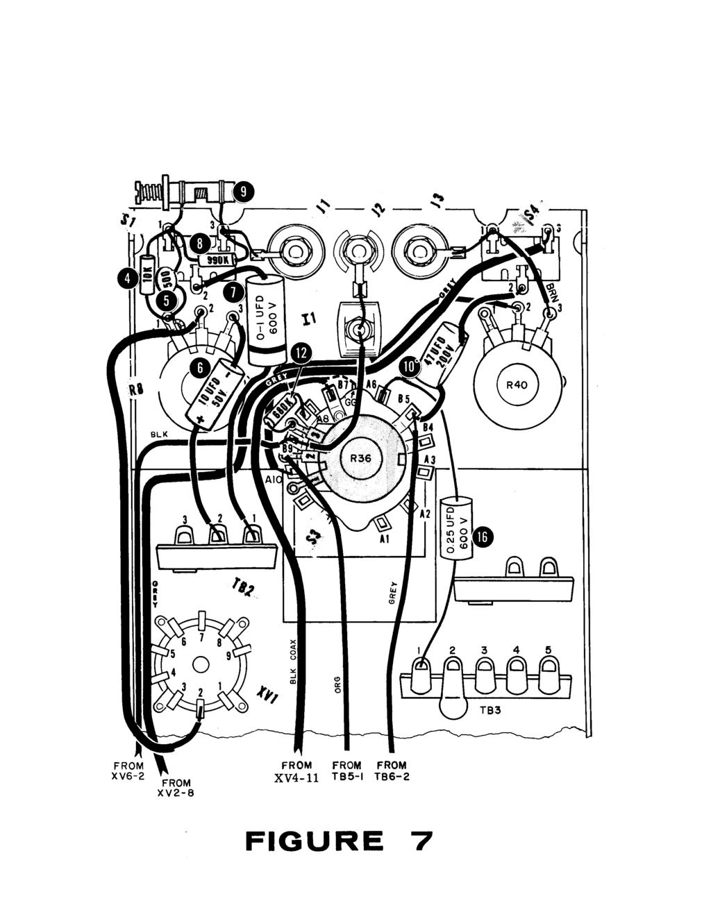
47
48
49
50
51
52
53

54
OPERATING INSTRUCTIONS FOR SYLVANIA. Type I08 Cathode-Ray Oscilloscope. Sylvania Electric Products Inc. Industrial Apparatus. Emporium, Pennsylvania
 OPERATING INSTRUCTIONS FOR SYLVANIA Type I08 Cathode-Ray Oscilloscope Sylvania Electric Products Inc. Industrial Apparatus Plant Emporium, Pennsylvania OPERATING INSTRUCTIONS FOR Sylvania Type 08 Cathode-Ray
MUK REAR PANEL ASSEMBLY ASSEMBLY INSTRUCTIONS
 Rev B. 13 August 2017 ASSEMBLY INSTRUCTIONS The Midnight Ultimate Keyer (MUK) consists of two functional assemblies: Rear Panel containing the interface and power connectors. Front Panel containing the
ASSEMBLY, INSTALLATION, AND REMOVAL OF CONTACTS AND MODULES
 ASSEMBLY, INSTALLATION, AND REMOVAL OF CONTACTS AND MODULES FOR 75 OHM AND 75 OHM HD COAXIAL CONTACTS AND MODULES Table of Contents SECTION 1 RECEIVER CONTACT ASSEMBLY INSTRUCTIONS SECTION 2 ITA CONTACT
Fixed Audio Output for the K2 Don Wilhelm (W3FPR) & Tom Hammond (NØSS) v August 2009
 & Tom Hammond (NØSS) v August 2009") Fixed Audio Output for the K2 Don Wilhelm (W3FPR) & Tom Hammond (NØSS) v. 2.1 06 August 2009 I have had several requests to provide a fixed audio output from the K2. After looking at the circuits that
Fixed Audio Output for the K2 Don Wilhelm (W3FPR) & Tom Hammond (NØSS) v. 2.1 06 August 2009 I have had several requests to provide a fixed audio output from the K2. After looking at the circuits that
Multi-Key v2.4 Multi-Function Amplifier Keying Interface
 Multi-Key v2.4 Multi-Function Amplifier Keying Interface ASSEMBLY & OPERATION INSTRUCTIONS INTRODUCTION The Harbach Electronics, LLC Multi-Key is a multi-function external device designed for the safe
Automatic Connector MHV Connectors MHV Introduction MHV series connectors Contents Polarized mating interfaces Anti-Rock mating interfaces
 Automatic s 2004 Automatic. All rights reserved. pdf 1.0 3-18-04 Contents Specifications........................... 2 Straight Cable Plugs...................... 3 Right Angle Cable Plugs...................
NewScope-7A Operating Manual
 2016 SIMMCONN Labs, LLC All rights reserved NewScope-7A Operating Manual Preliminary May 13, 2017 NewScope-7A Operating Manual 1 Introduction... 3 1.1 Kit compatibility... 3 2 Initial Inspection... 3 3
Tube Cricket Build Guide
 Tube Cricket Build Guide The Tube Cricket is a small-wattage amp that puts out about 1 watt of audio power. With a 12AU7 tube-preamp and a JRC386 power amp, the Tube Cricket gives you great tone in a compact
MAKE AN RGB CONTROL KNOB.
 MAKE AN RGB CONTROL KNOB. This is a knob based colour changing controller that uses a custom programmed microcontroller to pack a lot of features into a small affordable kit. The module can drive up to
Atari PICO Composite Mod Board Installation Instructions:
 Atari PICO Composite Mod Board Installation Instructions: Installation Guide 6 Switch Atari 2600 6 Switch Video Mod Installation Guide Disclaimer: I am not responsible for any damage done to your Atari.
HN Connectors. Automatic Connector. Introduction. Contents. 631/ FAX 631/
 Connectors Introduction 2004 Automatic Connector. All rights reserved. pdf 1.0 4-13-04 Contents Specifications........................... 2 Straight Cable Plugs...................... 3 Right Angle Cable
Build A Video Switcher
 Build A Video Switcher VIDEOSISTEMAS serviciotecnico@videosistemas.com www.videosistemas.com Reprinted with permission from Electronics Now Magazine September 1997 issue Copyright Gernsback Publications,
MclNTOSH MODEL C-4 and C-4P
 INSTRUCTION MANUAL MclNTOSH MODEL C-4 and C-4P AUDIO COMPENSATORS McINTOSH LABORATORY, INC. 320 Water St. Binghamton, N. Y. U.S.A. - 1 - INSTRUCTION MANUAL McINTOSH MODEL C-4 and C-4P AUDIO COMPENSATORS
Contents Section 9, Illustrated Parts
 Contents Section 9, Illustrated Parts Figures 9-1. Parts of RT7... 9-5 9-2. RT7 Drive Assembly... 9-9 9-3. RT7 Refrigeration System... 9-10 9-4. Parts of RT7 PLUS... 9-15 9-5. RT7 PLUS Drive Assembly...
Industrial Monitor Update Kit
 Industrial Monitor Update Kit (Bulletin Number 6157) Installation Instructions 2 Table of Contents Table of Contents Industrial Monitor Update Kit... 3 Overview... 3 Part 1 - Initial Preparation... 5 Part
OWNER'S MANUAL SIGNAL COMMANDER
 OWNER'S MANUAL SIGNAL COMMANDER THIS MANUAL CONTAINS INSTRUCTIONS FOR: LPDA 200 - INSTALLATION - OPERATION - TROUBLESHOOTING - EXPLODED PARTS DRAWING - WARRANTY AntennaTek, Inc. 425 S. Bowen, #4 Longmont,
PR-101 STEREO PREAMPLIFIER Phono Preamp ASSEMBLY MANUAL
 PR-101 STEREO PREAMPLIFIER Phono Preamp ASSEMBLY MANUAL 2016 AkitikA LLC All rights reserved Revision 1p18 March 12, 2016 Page 1 of 24 Table of Contents Table of Contents... 2 Table of Figures... 2 Section
IP-LINX Fiber :: X-XXXX
 Fiber :: 055-797X-XXXX User Manual Telect, Inc. All rights reserved. 146653-A0 Table of Contents Chapter 1: Introduction...3 1.1 Tools Required...3 1.2 Additional Parts...3 1.3 Assemblies...3 Chapter 2:
Non Magnetic Connectors
 Non Magnetic Connectors Johnson Components builds coaxial connectors using innovative materials and design to provide Mil Spec Performance at a commercial price. Now we offer our Non Magnetic Connectors
MONO AMPLIFIER KIT ESSENTIAL INFORMATION. Version 2.2 CREATE YOUR OWN SPEAKER DOCK WITH THIS
 ESSENTIAL INFORMATION BUILD INSTRUCTIONS CHECKING YOUR PCB & FAULT-FINDING MECHANICAL DETAILS HOW THE KIT WORKS CREATE YOUR OWN SPEAKER DOCK WITH THIS MONO AMPLIFIER KIT Version 2.2 Build Instructions
A449-6S 70 CENTIMETER FM YAGI ANTENNA MHz
 ASSEMBLY AND INSTALLATION A449-6S 70 CENTIMETER FM YAGI ANTENNA 440-450 MHz COMMUNICATIONS ANTENNAS 951425 (7/93) WARNING THIS ANTENNA IS AN ELECTRICAL CONDUCTOR. CONTACT WITH POWER LINES CAN RESULT IN
K Service Source. Apple High-Res Monochrome Monitor
 K Service Source Apple High-Res Monochrome Monitor K Service Source Specifications Apple High-Resolution Monochrome Monitor Specifications Characteristics - 1 Characteristics Picture Tube 12-in. diagonal
COLOUR CHANGING USB LAMP KIT
 TEACHING RESOURCES SCHEMES OF WORK DEVELOPING A SPECIFICATION COMPONENT FACTSHEETS HOW TO SOLDER GUIDE SEE AMAZING LIGHTING EFFECTS WITH THIS COLOUR CHANGING USB LAMP KIT Version 2.1 Index of Sheets TEACHING
OWNER'S MANUAL SIGNAL COMMANDER
 OWNER'S MANUAL SIGNAL COMMANDER THIS MANUAL CONTAINS INSTRUCTIONS FOR: MOD 550 - INSTALLATION - OPERATION - TROUBLESHOOTING - EXPLODED PARTS DRAWING - WARRANTY AntennaTek, Inc. 425 S. Bowen, #4 Longmont,
IP-LINX. Installation Guide
 Installation Guide Installation Guide, 146653-4 Copyright 2017, Telect, Inc. All Rights Reserved Telect and Connecting the Future are registered trademarks of Telect, Inc. 22425 East Appleway Ave. # 11
While the parts are already inventoried at the factory, please verify the inventory check as you go:
 Thank you for purchasing the kit for building the WJ9J DTMF controller. After building, you should read the document on operation (WJ9JDTMFControllerV5.pdf) in order to use. This is also in the link in
Instructions. Cable with Armor F CAUTION. October Rev A
 3M Single Conductor Accessory Breakout Kits (BOK's) for use with 3M Cable Accessories (Terminations, T-Bodies and Push-On Elbows) For Use With Single Conductor Accessories On Three-Core Conductor Cables
K Service Source. Apple High-Res Monochrome Monitor
 K Service Source Apple High-Res Monochrome Monitor K Service Source Specifications Apple High-Resolution Monochrome Monitor Specifications Characteristics - 1 Characteristics Picture Tube 12-in. diagonal
MASTR II BASE STATION 12/24V POWER SUPPLY 19A149979P1-120 VOLT/60 Hz 19A149979P2-230 VOLT/50 Hz
 Mobile Communications MASTR II BASE STATION 12/24V POWER SUPPLY 19A149979P1-120 VOLT/60 Hz 19A149979P2-230 VOLT/50 Hz CAUTION THESE SERVICING INSTRUCTIONS ARE FOR USE BY QUALI- FIED PERSONNEL ONLY. TO
Bill of Materials: Super Simple Water Level Control PART NO
 Super Simple Water Level Control PART NO. 2169109 Design a simple water controller in which electrodes are required to sense high and low water levels in a tank. Whenever the water level falls below the
Physics 123 Hints and Tips
 Physics 123 Hints and Tips Solderless Breadboards All of the analog labs and most of the digital labs will be built on the Proto-Board solderless breadboards. These provide three solderless breadboard
UNSIGNED HARDCOPY NOT CONTROLLED
 SUBJECT: APPROVED BY STATUS PURPOSE AFFECTED FUNCTIONS REFERENCES Cable and Harness Making Manager, Hardware Engineering Maintenance Revision Establishes requirements for the fabrication and inspection
Satellite Dish Installation Manual (Ver. 2) 1
 1") Satellite Dish Installation Manual Provided by DiscoverNet, Inc. Satellite Dish Installation Manual (Ver. 2) 1 Table of Contents Section 1: Introduction Page 3 Section 2: Recommended Tools and Materials
Satellite Dish Installation Manual Provided by DiscoverNet, Inc. Satellite Dish Installation Manual (Ver. 2) 1 Table of Contents Section 1: Introduction Page 3 Section 2: Recommended Tools and Materials
Multi-Media Installation Guide
 Multi-Media Installation Guide Coaxial Page 2 Data Plug Page 7 Data Jack Page 10 Telephone Page 13 Splicing Page 15 Cable Types Cable Types Two basic types of cable are used in multimedia installations.
Azatrax Model Railroad Track Signal Control - Single Track
 Installation Guide Azatrax Model Railroad Track Signal Control - Single Track TS2 What it is: The TS2 operates one or two trackside block signals (one in each direction) on one track to simulate the block
COHERENCE ONE PREAMPLIFIER
 COHERENCE ONE PREAMPLIFIER OWNER S MANUAL TABLE OF CONTENTS Introduction Features Unpacking Instructions Installation Phono Cartridge Loading Basic Troubleshooting Technical Specifications Introduction
Mal-2 assembly guide v1.0
 Mal-2 assembly guide v.0 SONIC POTIONS Schematic and BOM The BOM can be found on Google Docs Prepare the PCB Separate the PCBs using some pliers. PCB We start with the lower PCB and assemble it beginning
Medium Box for Cable Termination
 FIST-MB2-T I N S T A L L A T I O N I N S T R U C T I O N Medium Box for Cable Termination Contents 1 Introduction 1.1 Product description. 2 General 2.1 Tools 2.2 Kit contents 3 Installation and pre assembling
FIST-MB2-S. FIST Medium Box for Cable Splicing Only. 4 Cable installation. 1 Introduction. Contents. 2 General. 5. Fiber routing to individual trays
 FIST-MB2-S I N S T A L L A T I O N I N S T R U C T I O N FIST Medium Box for Cable Splicing Only Contents 1 Introduction 1.1 Product description 2 General 2.1 Tools 2.2 Kit contents 3 Installation and
3M Distribution Box (DDB)
") 3M Distribution Box (DDB) Merged Copper and Fiber Pole/Post Mount Enclosure Installation Instructions November 2015 78-0015-2736-1-A 2 November 2015 78-0015-2736-1-A Contents 1.0 General 2.0 Enclosure
3M Distribution Box (DDB) Merged Copper and Fiber Pole/Post Mount Enclosure Installation Instructions November 2015 78-0015-2736-1-A 2 November 2015 78-0015-2736-1-A Contents 1.0 General 2.0 Enclosure
C Connectors. Automatic Connector. Introduction. Contents. C Interface Options. 631/ FAX 631/
 utomatic onnector onnectors Introduction 2004 utomatic onnector. ll rights reserved. pdf 1.0.1 3-23-04 ontents Specifications........................... 2 Straight Plugs...................... 3 Right ngle
Etherwave Plus Field Upgrade Instructions
 Etherwave Plus Field Upgrade Instructions The Etherwave Plus Field Upgrade is an advanced project for upgrading a standard Moog Music Etherwave theremin to the Etherwave Plus. The new features of the Etherwave
A CENTIMETER FM YAGI ANTENNA MHz
 ASSEMBLY AND INSTALLATION A449-70 CENTIMETER FM YAGI ANTENNA 440-450 MHz COMMUNICATIONS ANTENNAS 951424 (10/91) WARNING THIS ANTENNA IS AN ELECTRICAL CONDUCTOR. CONTACT WITH POWER LINES CAN RESULT IN DEATH
Experiment 9A: Magnetism/The Oscilloscope
 Experiment 9A: Magnetism/The Oscilloscope (This lab s "write up" is integrated into the answer sheet. You don't need to attach a separate one.) Part I: Magnetism and Coils A. Obtain a neodymium magnet
Technical Information Bulletin
 June 4, 2001 #TIB0003 Units Affected: Model Serial Numbers Model Serial Numbers SVT-2PRO T2PDxxxxxxxxx SVTAV AXVDxxxxxxxxx ATLDxxxxxxxxx BJIDMAxxxxxxx SVT-2PROJ T2PJxxxxxxxxx SVTAVJ BAHJxxxxxxxxx ATLJxxxxxxxxx
August " BLANK PATCH PANEL FOR STP KEYSTONE JACKS. 19" PATCH PANEL - 24x STP CAT6A PORTS 19" BLANK PATCH PANEL FOR STP KEYSTONE JACKS
 19" BLANK PATCH PANEL FOR STP KEYSTONE JACKS WITH EXTRA LONG STRAIN RELIEF BAR The 24-port blank patch panel is designed to use with STP keystone jacks. It can hold up to 24 RJ45 keystone jacks. It features
PNP300 / PNP300UN / PNP350
 DOCUMENT NUMBER 400-0114-003 / UN / PNP350 Pop N Plug Slim INTERCONNECT BOX USER'S GUIDE TABLE OF CONTENTS Page PRECAUTIONS / SAFETY WARNINGS...2 GENERAL...2 INSTALLATION...2 CLEANING...2 ABOUT YOUR /300UN/350...3
Main PCB (The small one)
") Thanks for choosing our kits! This manual is written taking with the problems that we usually find in our workshops in mind. Also the order is meant to make assembly as easy as possible. Some steps are
Thanks for choosing our kits! This manual is written taking with the problems that we usually find in our workshops in mind. Also the order is meant to make assembly as easy as possible. Some steps are
National Wire and Cable and National Cable Molding Headquarters Los Angeles California
 National Wire and Cable and National Cable Molding Headquarters Los Angeles California CAPABILITIES Medical Business Machines Communications Equipment Computer Equipment Audio Systems General Instrumentation
SPECIAL SPECIFICATION 2344 TMC Support Equipment
 2004 Specifications CSJ 0912-00-488 SPECIAL SPECIFICATION 2344 TMC Support Equipment 1. Description. Furnish Traffic Management Center (TMC) support equipment in the City of Missouri City TMC location
DS1 Cross-Aisle Panel
 DS1 Cross-Aisle Panel Model 005-0005-0100 Installation Guide 1.1 Overview 1.1.1 Inspection Compare the contents of the DS1 Cross-Aisle Panel shipping container with the packing list. Call Telect if anything
Optical Distribution Box 300 Installation Guide. Version : R0.0
 Optical Distribution Box 300 Installation Guide Document No. : OD16-546-L-01 Version : R0.0 Date: 21-Mar-2018 IMPORTANT INSTRUCTIONS When using fiber optic equipment, basic precautions should always be
Cable ISOBUS Active Termination
 ISOBUS Retrofit Kit Ag Leader Technology Note: Indented items indicate parts included in an assembly listed above Part Name/Description Part Number Quantity ISOBUS Retrofit Kit 4100843 1 Hex Head Bolt
FOSC 450 C6 and D6 Closures
 FOSC 450 C6 and D6 Closures I N S T A L L A T I O N I N S T R U C T I O N Fiber Optic Splice Closure 1. General Product Information The FOSC 450 C6 and D6 fiber optic splice closures use compressed gel
OWNER'S MANUAL SIGNAL COMMANDER
 OWNER'S MANUAL SIGNAL COMMANDER THIS MANUAL CONTAINS INSTRUCTIONS FOR: LPDA 100 - INSTALLATION - OPERATION - TROUBLESHOOTING - EXPLODED PARTS DIAGRAM - WARRANTY AntennaTek, Inc. 425 S. Bowen, # 4 Longmont,
3M Cold Shrink Splice Kit QS-III 5416A
 3M Cold Shrink Splice Kit QS-III 5416A for Jacketed Concentric Neutral (JCN) and Concentric Neutral Cable Instructions IEEE Std. 404 15 kv Class 150 kv BIL CAUTION Working around energized systems may
S Regulators. Supplement 1. Contents. Control Replacement Assembly Installation Instructions Supplement
 Regulators Control Replacement Assembly Installation Instructions Supplement Service Information S225-40-1 Supplement 1 Figure 1. CL-6A Control Replacement Assembly. Contents Safety Information... 2 Product
2.4 METER SERIES 1250 ANTENNA SYSTEM
 June 1,2009 Revision B Assembly Manual 2.4 METER SERIES 1250 ANTENNA SYSTEM General Dynamics SATCOM Technologies 1500 Prodelin Drive Newton NC 28658 2.4 Meter 2 Piece Az/El Installation Instructions B
Table of Contents. Read This First.2. Introduction by Jim Fosgate...3. Unpacking..4. Tubes and Tube shield Installation 5. Product Placement...
 Owner s Manual Table of Contents Read This First.2 Introduction by Jim Fosgate...3 Unpacking..4 Tubes and Tube shield Installation 5 Product Placement...6 Connecting your Fosgate Signature..7 Phono stage
Assembling and Mounting the Presentation Display, Speakers, Speaker Screens, and Table Door
 CHAPTER 8 Assembling and Mounting the Presentation Display, Speakers, Speaker Screens, and Table Door July 13, 2012, This document provides you with the procedures you perform to assemble and mount the
A7 Owner's Manual ii
 Owner s Manual Table of Contents Introduction...1 Unpacking...2 Components...3 Assembling...4 Placing Stereo Loudspeakers...6 Connecting...7 Specifications...8 Warranty...9 030519 A7 Owner's Manual ii
3M Cold Shrink QS-III Silicone Rubber Splice Kit 5488A-TOW/WOT
 3M Cold Shrink QS-III Silicone Rubber Splice Kit 5488A-TOW/WOT For Tape Over Wire (TOW) and Wire-Over-Tape (WOT) Shielded Cable For 250 2000 kcmil cable with 650-mil primary insulation thickness Instructions
SUBCARRIER TRANSFER FILTER INSTRUCTION BOOK IB622702
 SCF611S SUBCARRIER TRANSFER FILTER INSTRUCTION BOOK IB622702 SCF611S SUBCARRIER TRANSFER FILTER TABLE OF CONTENTS PAGE SHIPPING INSPECTION 2 MODULE CONFIGURATION 2 INSTALLING MODULES 2-3 CABLING 3 FRONT
TV Lift System Model CL-65 Installation Instructions
 TV Lift System Model CL-65 Installation Instructions Contact: Support@Nexus21.com Toll Free: (866) 500-5438 Phone: (480) 951-6885 Fax: (480) 951-6879 Revised: 01/17/17 Below is a parts list describing
K Service Source. Macintosh Color Display
 K Service Source Macintosh Color Display K Service Source Specifications Macintosh Color Display Specifications Characteristics - 1 Characteristics Picture Tube 14-in. diagonal (11.5-in. viewable image)
2100/2200/4100/6200 & MPB Series Bottom Mount Drive Pack. for Standard Load Parallel Shaft 60 Hz Gearmotors
 00/00/400/600 & MPB Series Bottom Mount Drive Pack. for Standard Load Parallel Shaft 60 Hz Gearmotors Installation, Maintenance & Parts Manual DORNER MFG. CORP. INSIDE THE USA OUTSIDE THE USA P.O. Box
Table 4-1: Rating Levels
 OBJECTIVES 1. Describe various level ratings that apply to telecommunication cables and jacks and identify where each is implemented. 2. Describe the various levels of the cabling category rating systems.
4. Alignment and Adjustments
 4. Alignment and Adjustments 4-1 Preadjustment 4-1-1 Factory Mode 1. Do not attempt these adjustments in the Video Mode. 2. The Factory Mode adjustments are necessary when either the EEPROM (IC02) or the
apple Service Source Apple Studio Display 17" LCD (ADC) Updated 6 Decenber Apple Computer, Inc. All rights reserved.
 Updated 6 Decenber Apple Computer, Inc. All rights reserved.") apple Service Source Apple Studio Display 17" LCD (ADC) Updated 6 Decenber 2004 2003 Apple Computer, Inc. All rights reserved. apple Service Source Take Apart Apple Studio Display 17" LCD (ADC) 2003 Apple
apple Service Source Apple Studio Display 17" LCD (ADC) Updated 6 Decenber 2004 2003 Apple Computer, Inc. All rights reserved. apple Service Source Take Apart Apple Studio Display 17" LCD (ADC) 2003 Apple
SMA One Piece Semi-Rigid Connectors
 SMA One Piece Semi-Rigid Connectors The Johnson captivated solderless contact connectors for semi-rigid cable provide a unique solution for high frequency cable assemblers. As compared to standard solder-on
VITALink Taped Splice Straight Through Crimp
 A Marmon Wire & Cable Berkshire Hathaway Company VITALink Taped Splice Straight Through Crimp 2 Hour Fire-Rated Splice VITALink MC Cables, UL FHIT 120 Installation Instructions Description The VITALink
TeamWork Kits Installation Guide
 TX 0 RX COM +5V APARATUS US TeamWork Kits Installation Guide TeamWork 400 and TeamWork 600 Kits The TeamWork 400 and TeamWork 600 kits consist of an HDMI switcher, system controller, Cable Cubby, and cables
INSTALLATION MANUAL FOR THE TIMING LIGHT
 INSTALLATION MANUAL FOR THE TIMING LIGHT May 12 2014 SPORTS SPLIT STEP 12566 LAZY ACRES CRT NEVADA CITY, CA 95959 www.sports-split-step.com vicborg70@gmail.com 530-272-7345 1 1. The installation of the
SMA - 50 Ohm Connectors
 Alphabetical Index 142-0593-001 6 142-0593-006 6 142-0593-401 6 142-0593-406 6 142-0594-001 6 142-0594-006 6 142-0594-401 6 142-0594-406 6 142-0693-001 4 142-0693-006 4 142-0693-051 5 142-0693-056 5 142-0693-101
FOSC-600 C and D I N S T A L L A T I O N I N S T R U C T I O N
 FOSC-600 C and D I N S T A L L A T I O N I N S T R U C T I O N In-line and butt version Cold applied re-usable fiber optic closure Contents 1 Introduction 1.1 Product description 1.2 Capacity 2 General
VU-1 VU Meter Kit Volume Unit Meter
 VU-1 VU Meter Kit Volume Unit Meter Simplicity Counts, Detail Matters. No part of this document may be reproduced, either mechanically or electronically, posted online on the Internet, in whole or in part,
WINEGARD INSTALLATION MANUAL. Model GM Carryout Ladder Mount for mounting pipes with outer diameters between 1 to 1-1/8
 WINEGARD INSTALLATION MANUAL Model GM-3000 Carryout Ladder Mount for mounting pipes with outer diameters between 1 to 1-1/8 WARNING: DO NOT USE THE LADDER MOUNT AS A STEP! NOT INTENDED FOR USE WITH THE
IQPro Construction Notes by Gary Johnson, WB9JPS August 5, 2006
 IQPro Construction Notes by Gary Johnson, WB9JPS August 5, 2006 All parts of the enclosure were fabricated from 0.050 brass sheet, folded and soldered, with 0.187-thick brass strips soldered along edges
24-Fiber LANLINXS (Model # ) 48-Fiber LANLINXS (Model # ) User Manual
 48-Fiber LANLINXS (Model # ) User Manual") 24-Fiber LANLINXS (Model # 055-8632-5000) 48-Fiber LANLINXS (Model # 055-8832-5000) User Manual 24-Fiber LANLINXS (Model # 055-8632-5000) 48-Fiber LANLINXS (Model # 055-8832-5000) User Manual, Part Number
24-Fiber LANLINXS (Model # 055-8632-5000) 48-Fiber LANLINXS (Model # 055-8832-5000) User Manual 24-Fiber LANLINXS (Model # 055-8632-5000) 48-Fiber LANLINXS (Model # 055-8832-5000) User Manual, Part Number
ACCESSORIES MANUAL PART NUMBER: PRODUCT REVISION: 1 PNP202. Interconnect Box USER'S GUIDE
 MANUAL PART NUMBER: 400-0109-001 PRODUCT REVISION: 1 PNP202 Interconnect Box USER'S GUIDE INTRODUCTION Your purchase of the PNP202 Interconnect Box is greatly appreciated. We are sure you will find it
N3ZI Digital Dial Manual For kit with Backlit LCD Rev 4.00 Jan 2013 PCB
 N3ZI Digital Dial Manual For kit with Backlit LCD Rev 4.00 Jan 2013 PCB Kit Components Item Qty Designator Part Color/Marking PCB 1 LCD Display 1 LCD 1602 Volt Regulator 1 U1 78L05, Black TO-92 Prescaler
COMPOSITE VIDEO LUMINANCE METER MODEL VLM-40 LUMINANCE MODEL VLM-40 NTSC TECHNICAL INSTRUCTION MANUAL
 COMPOSITE VIDEO METER MODEL VLM- COMPOSITE VIDEO METER MODEL VLM- NTSC TECHNICAL INSTRUCTION MANUAL VLM- NTSC TECHNICAL INSTRUCTION MANUAL INTRODUCTION EASY-TO-USE VIDEO LEVEL METER... SIMULTANEOUS DISPLAY...
INSTRUMENT CATHODE-RAY TUBE
 Instrument cathode-ray tube D14-363GY/123 INSTRUMENT CATHODE-RAY TUBE mono accelerator 14 cm diagonal rectangular flat face internal graticule low power quick heating cathode high brightness, long-life
Theremino pulsometer
 Theremino System Theremino pulsometer Optical sensor for the arrhythmia detection theremino System - Pulsometer - December 8, 2017 - Page 1 Sensors of all types On the Internet there are many ideas to
HOM rev. new Heathkit of the Month #87: by Bob Eckweiler, AF6C. Heath of the Month #87 - Heathkit O-Series Oscilloscopes - Part II
 Heathkit of the Month #: by Bob Eckweiler, AF6C! ELECTRONIC TEST EQUIPMENT Heathkit O- through O- Oscilloscopes. Introduction: In the June RF Newsletter the first four Heathkit Oscilloscopes were discussed;
Build Your Own Clone Super 8 Kit Instructions
 Build Your Own Clone Super 8 Kit Instructions Warranty: BYOC, Inc. guarantees that your kit will be complete and that all parts and components will arrive as described, functioning and free of defect.
Operating Manual. Automated Gear. Apollo Design Technology, Inc Fourier Drive Fort Wayne, IN USA
 Operating Manual Automated Gear Apollo Design Technology, Inc. 4130 Fourier Drive Fort Wayne, IN 46818 USA PH: +01(260)497-9191 FX: +01(260)497-9192 www.apollodesign.net 11-25-09 5-6 POWERING UP THE RIGHT
Sphinx II. Owner s Manual. Tube Hybrid Integrated Power Amplifier. Rogue Audio, Inc. 3 Marian Lane Brodheadsville, PA Issue date: 08/01/16
 Sphinx II Tube Hybrid Integrated Power Amplifier Owner s Manual Rogue Audio, Inc. 3 Marian Lane Brodheadsville, PA 18322 Issue date: 08/01/16 TABLE OF CONTENTS 1) Introduction 2 2) Unpacking the Sphinx
TNC Connectors. RF Coax Connectors. Product Facts
 Product Facts Hex Crimp and Connectors 50 and 75 ohm commercial versions available Provides excellent performance at frequencies up to 7 GHz ow cost commercial type available type is smaller and lighter
Product Manual MNX10015 / REV C MODEL SB142, SB242. Dual Output Series Switch Boxes
 Product Manual MNX10015 / REV C MODEL SB142, SB242 Dual Output Series Switch Boxes Contents Section I Overview Introduction.... 2 Description... 2 Section II Installation Mounting... 3 Electrical Connections...
6000 Series Patch Panel Terminating Instructions
 6000 Series Patch Panel Terminating Instructions INTRODUCTION The 6000 Series patch panels include a unique feature not found on any other patch panel. This feature allows you to angle each of the four
Solid-State Digital Timer
 Solid-State Digital Timer 1/16 DIN, Digital-Set Timer with 0.1 Second to 9,990 Hours Range 8 field-selectable operation modes Universal AC/DC supply voltage timers available Operations include ON-delay,
APPLIANCES /// MTA, CST-100 II AND SL-156 CONNECTORS. CONNECTORS/ APPLIANCES MTA, CST-100 II and SL-156 Connectors
 PPLINCES /// MT, CST-100 II ND SL-156 CONNECTORS CONNECTORS/ PPLINCES MT, CST-100 II and SL-156 Connectors Contents Introduction This catalog has been designed to assist you, our customer, identify products
LUDLUM MODEL 43-5 ALPHA SCINTILLATOR. March 2011
 LUDLUM MODEL 43-5 ALPHA SCINTILLATOR LUDLUM MODEL 43-5 ALPHA SCINTILLATOR STATEMENT OF WARRANTY Ludlum Measurements, Inc. warrants the products covered in this manual to be free of defects due to workmanship,
Total solder points: 123 Difficulty level: beginner 1. advanced AUDIO ANALYZER K8098. audio gea Give your. . high-tech ILLUSTRATED ASSEMBLY MANUAL
 Total solder points: 123 Difficulty level: beginner 1 2 3 4 5 advanced AUDIO ANALYZER K8098 ra audio gea Give your. look high-tech ILLUSTRATED ASSEMBLY MANUAL H8098IP-1 Features & Specifications Features
OCT 15 Rev B
 AMP+ HVA280-3pxm XE High-Voltage Plug Connector with 1-Stage Latching Application Specification 114-32125 15 OCT 15 Rev B NOTE All numerical values are in metric units [with U.S. customary units in brackets].
Introduction 1. Green status LED, controlled by output signal ST. Sounder, controlled by output signal Q6. Push switch on input D6
 Introduction 1 Welcome to the GENIE microcontroller system! The activity kit allows you to experiment with a wide variety of inputs and outputs... so why not try reading sensors, controlling lights or
PNP300 & PNP350 POP N PLUG SLIM INTERCONNECT BOX USER S GUIDE
 The is shown above. MANUAL PART NUMBER: 400-0114-004 & PNP350 POP N PLUG SLIM INTERCONNECT BOX USER S GUIDE TABLE OF CONTENTS Page PRECAUTIONS / SAFETY WARNINGS... 2 GENERAL...2 HANDLING...2 CLEANING...2
Obtained from Omarshauntedtrail.com
 http://www.cindybob.com/halloween/ledlighting/ledspotlights/ Introduction In our 2005 haunt providing 120V AC power to the various lights and props requiring it became a fairly large problem. Extension
RCA PLUGS & JACKS Bulk Pkg (2) Bulk Pkg (2) Bulk Pkg (2) Bulk Pkg (2)
 Bulk Pkg (2) Bulk Pkg (2) Bulk Pkg (2)") RCA PLUGS & JACKS 24-100-0 Bulk 24-100-2 Pkg (2) Metal body RCA plug. Maximum cable dia. 7.5mm 24-104-0 Bulk 24-104-2 Pkg (2) Metal plug with strain relief. Maximum cable dia. 4.5mm Use 84-156-1 tool for
RCA PLUGS & JACKS 24-100-0 Bulk 24-100-2 Pkg (2) Metal body RCA plug. Maximum cable dia. 7.5mm 24-104-0 Bulk 24-104-2 Pkg (2) Metal plug with strain relief. Maximum cable dia. 4.5mm Use 84-156-1 tool for