Dynamic Animation Cube Group 1 Joseph Clark Michael Alberts Isaiah Walker Arnold Li
|
|
|
- Winfred Barber
- 5 years ago
- Views:
Transcription
1 Dynamic Animation Cube Group 1 Joseph Clark Michael Alberts Isaiah Walker Arnold Li Sponsored by: Department of Electrical Engineering & Computer Science at UCF

2 What is the DAC? The DAC is an array of LEDs assembled in a 16 * 16 * 16 array designed to simulate animation by producing images in 3-dimensional space in the Red, Green, Blue color spectrum.
3 Specifications Cube size: 3.5 x 3.5 x 4 ft (L x W x H) Visible sides: 5 sides Light Emitting Diode type: RGB Pixel resolution: 16 x 16 x 16 = 4096 Case construction: Transparent acrylic Communication: USB/ SD card controller Working temperature: F Working Humidity: 10-80% Working Voltage: AC 110V-230V Number of animations: 100
4 What hardware is required? Microcontroller LED Drivers Resistors Capacitors PNP transistors UART connection Computer power supply DC/DC step down voltage regulator Designed Printed Circuit board 4,096 RGB common anode LEDs 1 SDHC card

5

6
7 What are the hardwares functions? Store the animations that are to be displayed. Select the layer that is to be illuminated to display the animation. Provide current to the required diode to provide the desired color.
8 What software is required? Sprite implementation program to design the animations to be displayed on the cube. Cube operating code.
9 What are the software functions? Sprite implementation program: o Take the animations designed by the sure and write them into code that can be read by the microcontroller. Cube operating code: o Take the animation code written by the sprite implementation program and use it to display the desired images.

10 How does the DAC work?
11 What LED driver to select? Led Driver Outputs Gray Scale Control Brightness Control Error Detecti on Cost Per Driver TLC bit 7-bit No $1.79 TLC bit N/A Yes $3.53 TLC bit 6-bit Yes $3.36 LT bit 6-bit Yes $6.07

12 What are the benefits of the TLC5941? 16 Channels with 6-bit Dot correction Controlled In-Rush Current Two Separate Error Information Circuits 12-Bit Pulse Width Modulation Grayscale Control Current Accuracy
13 Stellaris LM3S bit ARM Cortex-M3 50-MHz processor core 256 KB flash and 64 KB SRAM 42 GPIOs Bit-Banding UART Synchronous serial interface (SSI) Pulse width modulation

14 TLC5941 LED Driver 1 st PCB will contain the LED drivers Ability to arrange devices in cascade allows a single control line to transmit data to an individual array of drivers

15 TLC5941 LED Driver 2 control lines per color o Best way to ensure that ideal amount of frames per second were displayed

16 Surface mount Vs. Dip Surface mount takes up significantly less space than dip A major factor in PCB design because 48 TLCs will be used to drive the LEDs
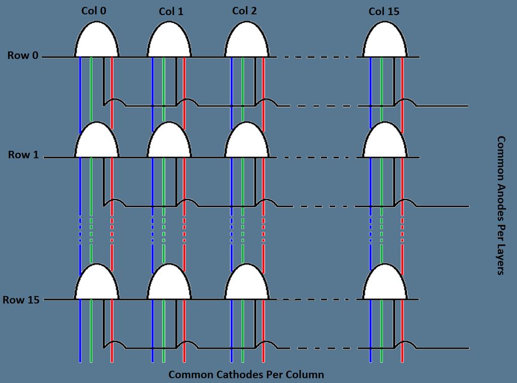
17 LED Lattice 5cm pitch This allows for the best possible viewing orientation If LEDs are too close together it would be impossible to see through the cube Arranged in a 16 x 16 x 16 architecture An RGB LED is actually three separate LEDs inside one "bulb" One common anode, three common cathodes
18

19 Layer Select 2 nd PCB will contain the Stellaris Stellaris uses 16 GPIOs to control which layer is selected. Sends output to array of transistors on separate PCB
20 Layer Select 3 rd PCB will contain the layer select transistors Transistors Receive Layer Select From MCU Output goes directly to layer 0 through 15
21 Displaying Images MCU sends data serially to the array of TLC5941s 2 input lines per color Other signals sent: o Latch o Output Enable o Input Clock o PWM Clock

22 Displaying Images Data received by drivers Held in internal registers until latch signal received
23 Displaying Images Layer is selected; states of LEDs are displayed Layer is turned off; Data is erased from the TLC Repeat Process 16 times for one frame
24 Current Requirements Maximum current draw of the LEDs is determined by assuming all LEDs in one layer are turned on at a single instant: o A single LED needs 20 ma of current to be in the on state o There are 256 LEDs per layer, if all LEDs are lit that is 5.12 A drawn. We will use a 5V computer power supply to step down to 3.3 V for the Stellaris Minimum current: 48 ma (Stellaris) + 3 x 50 ma (LED driver) + 0 x 20mA (LEDs) =.198 A ± 10% Maximum current: 48 ma (Stellaris) + 3 x 50 ma (LED driver) x 20mA (LEDs) = A ± 10%
25 Multiplexing Almost all LED cubes rely on persistence of vision. An entire image is made up of 16 layers Impractical to light up all 16 layers at once as we would need IO ports 1 Frame: a. Layer 0 is switched on for a short duration, a section of the image is displayed, then switched off b. Repeat for all 16 layers

26 Multiplexing
27 Persistence of Vision The effect is that the image is perceived as a whole by the viewer as long as the entire path is completed during the visual persistence time of the human eye. Our goal is to produce a 24 frame/second animation One image requires: 16 layers x 24 frames /sec = 384 layer selects/sec Almost all LED cubes rely on persistence of vision.
28 Pulse Width Modulation Without PWM the cube could only display red, green, or blue for each LED With PWM there are thousands of colors to choose from This is done by adjusting the brightness of each individual LED diode in a particular bulb o This allows the cube to turn on multiple colors without drawing too much current PWM is performed by the LED drivers Each output can have a value of 0 to 4096 because the length of a single output from the TLC is 12 bits
29 Color Wheel
30 phase < colorwheellength/3 r = maxbitcolor x sin(π x phase / (2 *colorwheellength/3)) g = 0 b = maxbitcolor x cos(π x phase / (2 *colorwheellength/3)) phase < 2 * colorwheellength/3 r = maxbitcolor x cos(π x (phase - colorwheellength/3) / (2 *colorwheellength/3)) g = maxbitcolor x sin(π x (phase - colorwheellength/3) / (2 *colorwheellength/3)) b = 0 phase < colorwheellength r = 0 g = maxbitcolor x cos(π x (phase - 2 *colorwheellength/3) / (2 *colorwheellength/3)) b = maxbitcolor x sin(π x (phase - 2 *colorwheellength/3) / (2 *colorwheellength/3))
31 red(phase) = 0 <= phase < colorwheellength/3 red(0) = maxbitcolor x sin(0) red = 0 - no red red(colorwheellength/3) = maxbitcolor x sin(π/2) red = maxbitcolor - max red
32 Animations The LEDs will be controlled using an animation file The color and location of which LEDs will be lit will be determined by the animation file SD Card will hold the animations Two Types of Animation Sprite based Function based
33 Sprite Animations Sprite based animations use the concept of sprites A group of images are displayed in sequence to make an animation This is done fast enough to create the sense of motion They will each have a specific number of frames and a specified frame delay
34 Function Animations Used for the more random based animations or animations with a strict pattern Such as a rain animation or moving cubes in a set pattern They will each have a set parameters and a duration
35 Creating Animations Sprite based animations will be created using a standalone program that will produce file that can be read from the SD Card Function based animations will be functions already defined and given variables from the SD Card

36 Displaying Animations
37 Class Diagram
38 Interrupt Service Routine The cube will have one ISR Its only job is to read the SD Card to display the animations Will simply loop through all the data on the SD Card forever
39 What is the budget? Components Cost per piece # of pieces Total LED Drivers $ Sampled Microcontroller $ Sampled LED $0.14 4,300 $ PCB TBD 2 TBD Resistors & Capacitors $0.10-$ $48.49 UART $ Sampled PNP Transistors $ $13.12 Total $ The University of Central Florida Department of Electrical Engineering & Computer Science has provided the group with an endowment of $1,000 for the completion of this project.
40 How far are we?
41 What is our time line?
42 Obstacles The cube will be 16 x 16 x 16 Size of the cube Prototype didn't work Stellaris MCU Testing LEDs Time
43 Problems to be solved Image storage o 24 fps / (144 fpg * 2gig) = 12 sec of animation o Use another storage medium? o 2 gig partitions? How to select? o USB to Synchronous Serial Interface (SSI)?
44
45 Questions?
Embedded System Training Module ABLab Solutions
 Embedded System Training Module ABLab Solutions www.ablab.in Table of Contents Course Outline... 4 1. Introduction to Embedded Systems... 4 2. Overview of Basic Electronics... 4 3. Overview of Digital
The Infinity Portal Craig A. Lindley 03/16/2011
 OK, I'll admit it. I'm a sucker for colored flashing lights especially if controlled by a micro processor (up). So recently when I came upon a really good deal on RGB LEDs on ebay and another really good
Published in A R DIGITECH
 Design of propeller clock by using 8051 Microcontroller Ahmed H. Al-Saadi*1 *1 (B.Sc. of Computer Engineering in Al Hussein University College of Engineering, Iraq) ah9@outlook.com*1 Abstract The propeller
Multi-Function Hexahedron An Interactive LED Cube
 Multi-Function Hexahedron An Interactive LED Cube Roberto Amaya, Luis Ferrer, Eury Reynoso, and Julio Romero College of Engineering and Computer Science, University of Central Florida, Orlando, Florida,
MBI5050 Application Note
 MBI5050 Application Note Foreword In contrast to the conventional LED driver which uses an external PWM signal, MBI5050 uses the embedded PWM signal to control grayscale output and LED current, which makes
Design and Implementation of an AHB VGA Peripheral
 Design and Implementation of an AHB VGA Peripheral 1 Module Overview Learn about VGA interface; Design and implement an AHB VGA peripheral; Program the peripheral using assembly; Lab Demonstration. System
Digital Effects Pedal Description Ross Jongeward 10 December 2014
 Digital Effects Pedal Description Ross Jongeward 10 December 2014 1 Contents Section Number Title Page 1.1 Introduction..3 2.1 Project Electrical Specifications..3 2.1.1 Project Specifications...3 2.2.1
Combinational vs Sequential
 Combinational vs Sequential inputs X Combinational Circuits outputs Z A combinational circuit: At any time, outputs depends only on inputs Changing inputs changes outputs No regard for previous inputs
Design and Implementation of Timer, GPIO, and 7-segment Peripherals
 Design and Implementation of Timer, GPIO, and 7-segment Peripherals 1 Module Overview Learn about timers, GPIO and 7-segment display; Design and implement an AHB timer, a GPIO peripheral, and a 7-segment
Optimized design for controlling LED display matrix by an FPGA board
 Journal of Advanced Computer Science & Technology, 3 (2) (24) 2-28 Science Publishing Corporation www.sciencepubco.com/index.php/jacst doi:.449/jacst.v3i2.288 Research Paper Optimized design for controlling
ECE 372 Microcontroller Design
 E.g. Port A, Port B Used to interface with many devices Switches LEDs LCD Keypads Relays Stepper Motors Interface with digital IO requires us to connect the devices correctly and write code to interface
ANDpSi025TD-LED 320 x 240 Pixels TFT LCD Color Monitor
 320 x 240 Pixels TFT LCD Color Monitor The ANDpSI025TD-LED is a 2.5 active matrix color TFT LCD module, that is suitable for applications such as a portable television (NTSC), camcorder, digital camera
Project Final Report. Z8 Arcade! 4/25/2006 James Bromwell,
 Project Final Report Z8 Arcade! 4/25/2006 James Bromwell, bromwell@gwu.edu Project Abstract Z8 Arcade! is an extension of the presentation on adding a composite video output line to the Z8 project board,
Pivoting Object Tracking System
 Pivoting Object Tracking System [CSEE 4840 Project Design - March 2009] Damian Ancukiewicz Applied Physics and Applied Mathematics Department da2260@columbia.edu Jinglin Shen Electrical Engineering Department
TIL311 HEXADECIMAL DISPLAY WITH LOGIC
 TIL311 Internal TTL MSI IC with Latch, Decoder, and Driver 0.300-Inch (7,62-mm) Character Height Wide Viewing Angle High Brightness Left-and-Right-Hand Decimals Constant-Current Drive for Hexadecimal Characters
UNIT V 8051 Microcontroller based Systems Design
 UNIT V 8051 Microcontroller based Systems Design INTERFACING TO ALPHANUMERIC DISPLAYS Many microprocessor-controlled instruments and machines need to display letters of the alphabet and numbers. Light
EEM Digital Systems II
 ANADOLU UNIVERSITY DEPARTMENT OF ELECTRICAL AND ELECTRONICS ENGINEERING EEM 334 - Digital Systems II LAB 3 FPGA HARDWARE IMPLEMENTATION Purpose In the first experiment, four bit adder design was prepared
Design and analysis of microcontroller system using AMBA- Lite bus
 Design and analysis of microcontroller system using AMBA- Lite bus Wang Hang Suan 1,*, and Asral Bahari Jambek 1 1 School of Microelectronic Engineering, Universiti Malaysia Perlis, Perlis, Malaysia Abstract.
8 PIN PIC PROGRAMMABLE BOARD (DEVELOPMENT BOARD & PROJECT BOARD)
") ESSENTIAL INFORMATION BUILD INSTRUCTIONS CHECKING YOUR PCB & FAULT-FINDING MECHANICAL DETAILS HOW THE KIT WORKS LEARN ABOUT PROGRAMMING WITH THIS 8 PIN PIC PROGRAMMABLE BOARD (DEVELOPMENT BOARD & PROJECT
ESSENTIAL INFORMATION BUILD INSTRUCTIONS CHECKING YOUR PCB & FAULT-FINDING MECHANICAL DETAILS HOW THE KIT WORKS LEARN ABOUT PROGRAMMING WITH THIS 8 PIN PIC PROGRAMMABLE BOARD (DEVELOPMENT BOARD & PROJECT
AND-TFT-64PA-DHB 960 x 234 Pixels LCD Color Monitor
 960 x 234 Pixels LCD Color Monitor The AND-TFT-64PA-DHB is a compact full color TFT LCD module, that is suitable for applications such as a car TV, portable DCD, GPS, multimedia applications and other
BCCU Brightness and Color Control Unit. XMC microcontrollers September 2016
 Brightness and Color Control Unit XMC microcontrollers September 2016 Agenda 1 2 3 4 5 6 7 Overview Key feature: Automatic high frequency brightness modulation Key feature: Automatic exponential dimming
Alice EduPad for Tiva or MSP432 TI ARM Launchpad. User s Guide Version /23/2017
 Alice EduPad for Tiva or MSP432 TI ARM Launchpad User s Guide Version 1.02 08/23/2017 1 Table OF Contents Chapter 1. Overview... 3 1.1 Welcome... 3 1.2 Tiva Launchpad features... 4 1.3 Alice EduPad hardware
VGA Controller. Leif Andersen, Daniel Blakemore, Jon Parker University of Utah December 19, VGA Controller Components
 VGA Controller Leif Andersen, Daniel Blakemore, Jon Parker University of Utah December 19, 2012 Fig. 1. VGA Controller Components 1 VGA Controller Leif Andersen, Daniel Blakemore, Jon Parker University
TV Synchronism Generation with PIC Microcontroller
 TV Synchronism Generation with PIC Microcontroller With the widespread conversion of the TV transmission and coding standards, from the early analog (NTSC, PAL, SECAM) systems to the modern digital formats
A MISSILE INSTRUMENTATION ENCODER
 A MISSILE INSTRUMENTATION ENCODER Item Type text; Proceedings Authors CONN, RAYMOND; BREEDLOVE, PHILLIP Publisher International Foundation for Telemetering Journal International Telemetering Conference
Keyboard Controlled Scoreboard
 Universities Research Journal 2011, Vol. 4, No. 4 Keyboard Controlled Scoreboard Kyaw Hlaing 1 and Win Swe 2 Abstract The objective of this research work is to design a keyboard controlled scoreboard that
PROTOTYPING AN AMBIENT LIGHT SYSTEM - A CASE STUDY
 PROTOTYPING AN AMBIENT LIGHT SYSTEM - A CASE STUDY Henning Zabel and Achim Rettberg University of Paderborn/C-LAB, Germany {henning.zabel, achim.rettberg}@c-lab.de Abstract: This paper describes an indirect
Digital Systems Principles and Applications. Chapter 1 Objectives
 Digital Systems Principles and Applications TWELFTH EDITION CHAPTER 1 Introductory Concepts Modified -J. Bernardini Chapter 1 Objectives Distinguish between analog and digital representations. Describe
LED Array Tutorial. This guide explains how to set up and operate the LED arrays that can be used for your. Internal Structure of LED Array
 LED Array Tutorial This guide explains how to set up and operate the LED arrays that can be used for your final EE 271 project. This tutorial is directed towards the FYM12882AEG 8x8 LED array, but these
Design and Implementation of SOC VGA Controller Using Spartan-3E FPGA
 Design and Implementation of SOC VGA Controller Using Spartan-3E FPGA 1 ARJUNA RAO UDATHA, 2 B.SUDHAKARA RAO, 3 SUDHAKAR.B. 1 Dept of ECE, PG Scholar, 2 Dept of ECE, Associate Professor, 3 Electronics,
Timing Pulses. Important element of laboratory electronics. Pulses can control logical sequences with precise timing.
 Timing Pulses Important element of laboratory electronics Pulses can control logical sequences with precise timing. If your detector sees a charged particle or a photon, you might want to signal a clock
16 Stage Bi-Directional LED Sequencer
 16 Stage Bi-Directional LED Sequencer The bi-directional sequencer uses a 4 bit binary up/down counter (CD4516) and two "1 of 8 line decoders" (74HC138 or 74HCT138) to generate the popular "Night Rider"
CHAPTER1: Digital Logic Circuits
 CS224: Computer Organization S.KHABET CHAPTER1: Digital Logic Circuits 1 Sequential Circuits Introduction Composed of a combinational circuit to which the memory elements are connected to form a feedback
V6118 EM MICROELECTRONIC - MARIN SA. 2, 4 and 8 Mutiplex LCD Driver
 EM MICROELECTRONIC - MARIN SA 2, 4 and 8 Mutiplex LCD Driver Description The is a universal low multiplex LCD driver. The version 2 drives two ways multiplex (two blackplanes) LCD, the version 4, four
IS01BFRGB LCD SmartDisplay from NKK Switches Simple implementation featuring the ATmega88PA from Atmel Complete software solution
 DKAN0003A Controlling the SmartDisplay with a SPI Peripheral 09 June 009 Features IS01BFRGB LCD SmartDisplay from NKK Switches Simple implementation featuring the ATmega88PA from Atmel Complete software
Data Sheet. Electronic displays
 Data Pack F Issued November 0 029629 Data Sheet Electronic displays Three types of display are available; each has differences as far as the display appearance, operation and electrical characteristics
BUSES IN COMPUTER ARCHITECTURE
 BUSES IN COMPUTER ARCHITECTURE The processor, main memory, and I/O devices can be interconnected by means of a common bus whose primary function is to provide a communication path for the transfer of data.
Module 4: Traffic Signal Design Lesson 1: Traffic Signal (Arduino) Control System Laboratory Exercise Grade 6-8
 Control System Laboratory Exercise Grade 6-8") Name: Class: Module 4: Traffic Signal Design Lesson 1: Traffic Signal (Arduino) Control System Laboratory Exercise Grade 6-8 Background Traffic signals are used to control traffic that flows in opposing
Name: Class: Module 4: Traffic Signal Design Lesson 1: Traffic Signal (Arduino) Control System Laboratory Exercise Grade 6-8 Background Traffic signals are used to control traffic that flows in opposing
Overview of All Pixel Circuits for Active Matrix Organic Light Emitting Diode (AMOLED)
") Chapter 2 Overview of All Pixel Circuits for Active Matrix Organic Light Emitting Diode (AMOLED) ---------------------------------------------------------------------------------------------------------------
Chapter 2 Overview of All Pixel Circuits for Active Matrix Organic Light Emitting Diode (AMOLED) ---------------------------------------------------------------------------------------------------------------
9/23/2014. Andrew Costin, Tom Syster, Ryan Cramer Advisor: Professor Hack Instructor: Professor Lin May 5 th, 2014
 Andrew Costin, Tom Syster, Ryan Cramer Advisor: Professor Hack Instructor: Professor Lin May 5 th, 2014 1 Problem Statement Introduction Executive Summary Requirements Project Design Activities Project
Super-Doubler Device for Improved Classic Videogame Console Output
 Super-Doubler Device for Improved Classic Videogame Console Output Initial Project Documentation EEL4914 Dr. Samuel Richie and Dr. Lei Wei September 15, 2015 Group 31 Stephen Williams BSEE Kenneth Richardson
Types of CRT Display Devices. DVST-Direct View Storage Tube
 Examples of Computer Graphics Devices: CRT, EGA(Enhanced Graphic Adapter)/CGA/VGA/SVGA monitors, plotters, data matrix, laser printers, Films, flat panel devices, Video Digitizers, scanners, LCD Panels,
Alice EduPad Board. User s Guide Version /11/2017
 Alice EduPad Board User s Guide Version 1.02 08/11/2017 1 Table OF Contents Chapter 1. Overview... 3 1.1 Welcome... 3 1.2 Launchpad features... 4 1.3 Alice EduPad hardware features... 4 Chapter 2. Software
Chrontel CH7015 SDTV / HDTV Encoder
 Chrontel Preliminary Brief Datasheet Chrontel SDTV / HDTV Encoder Features 1.0 GENERAL DESCRIPTION VGA to SDTV conversion supporting graphics resolutions up to 104x768 Analog YPrPb or YCrCb outputs for
Senior Design Report. Multi-Functional Hexahedron: An Interactive LED Cube. Group 5 Team Members: Roberto Amaya. Luis Ferrer.
 4000 Central Florida Blvd Orlando, FL32816-2993 Senior Design Report Multi-Functional Hexahedron: An Interactive LED Cube Group 5 Team Members: Roberto Amaya Luis Ferrer Eury Reynoso Julio Romero Table
EECS145M 2000 Midterm #1 Page 1 Derenzo
 UNIVERSITY OF CALIFORNIA College of Engineering Electrical Engineering and Computer Sciences Department EECS 145M: Microcomputer Interfacing Laboratory Spring Midterm #1 (Closed book- calculators OK) Wednesday,
Interfacing the TLC5510 Analog-to-Digital Converter to the
 Application Brief SLAA070 - April 2000 Interfacing the TLC5510 Analog-to-Digital Converter to the TMS320C203 DSP Perry Miller Mixed Signal Products ABSTRACT This application report is a summary of the
DIGITAL ELECTRONICS MCQs
 DIGITAL ELECTRONICS MCQs 1. A 8-bit serial in / parallel out shift register contains the value 8, clock signal(s) will be required to shift the value completely out of the register. A. 1 B. 2 C. 4 D. 8
Data Sheet. HDSP-573x Seven Segment Displays for High Light Ambient Conditions. Description. Features
 HDSP-x Seven Segment Displays for High Light Ambient Conditions Data Sheet High Efficiency Red: HDSP-900 Series Yellow: HDSP-00/-10/-0/-00 Series Description The HDSP-900 and HDSP-00/-10/-0/-00 are. mm,
CONTENTS. Section 1 Document Descriptions Purpose of this Document... 2
 CONTENTS Section 1 Document Descriptions... 2 1.1 Purpose of this Document... 2 1.2 Nomenclature of this Document... 2 Section 2 Solution Overview... 4 2.1 General Description... 4 2.2 Features and Functions...
Design of Vision Embedded Platform with AVR
 Design of Vision Embedded Platform with AVR 1 In-Kyu Jang, 2 Dai-Tchul Moon, 3 Hyoung-Kie Yoon, 4 Jae-Min Jang, 5 Jeong-Seop Seo 1 Dept. of Information & Communication Engineering, Hoseo University, Republic
Introduction. ECE 153B Sensor & Peripheral Interface Design Winter 2016
 Introduction ECE 153B Sensor & Peripheral Interface Design Course Facts Instructor Dr. John M. Johnson (johnson@ece.ucsb.edu) Harold Frank Hall 3165 Office hours: Monday and Wednesday, 12:30 1:30 PM Lecture
Linsn TS802 LED Card,SD802D LED Control Card
 Linsn TS802 LED Card,SD802D LED Control Card Linsn >> LED Sending Card >> TS802 LED Card TS802 LED Sending Card,SD802D LED Data Transmitter Function:Receiving signals from computer then fedding to receiving
SignalTap Plus System Analyzer
 SignalTap Plus System Analyzer June 2000, ver. 1 Data Sheet Features Simultaneous internal programmable logic device (PLD) and external (board-level) logic analysis 32-channel external logic analyzer 166
Sequential Logic. Introduction to Computer Yung-Yu Chuang
 Sequential Logic Introduction to Computer Yung-Yu Chuang with slides by Sedgewick & Wayne (introcs.cs.princeton.edu), Nisan & Schocken (www.nand2tetris.org) and Harris & Harris (DDCA) Review of Combinational
Hardware Design Considerations for a Wireless LED Based Display Design
 International Journal of Emerging Engineering Research and Technology Volume 3, Issue 11, November 2015, PP 50-57 ISSN 2349-4395 (Print) & ISSN 2349-4409 (Online) Hardware Design Considerations for a Wireless
4.3inch 480x272 Touch LCD (B) User Manual
 User Manual") 4.3inch 480x272 Touch LCD (B) User Manual Chinese website: www.waveshare.net English Website: www.wvshare.com Data download: www.waveshare.net/wiki Shenzhen Waveshare Electronics Ltd. Co. 1 目录 1. Overview...
4.3inch 480x272 Touch LCD (B) User Manual Chinese website: www.waveshare.net English Website: www.wvshare.com Data download: www.waveshare.net/wiki Shenzhen Waveshare Electronics Ltd. Co. 1 目录 1. Overview...
Solutions to Embedded System Design Challenges Part II
 Solutions to Embedded System Design Challenges Part II Time-Saving Tips to Improve Productivity In Embedded System Design, Validation and Debug Hi, my name is Mike Juliana. Welcome to today s elearning.
Chapter 9 MSI Logic Circuits
 Chapter 9 MSI Logic Circuits Chapter 9 Objectives Selected areas covered in this chapter: Analyzing/using decoders & encoders in circuits. Advantages and disadvantages of LEDs and LCDs. Observation/analysis
OLED THE PERFECT HIGH-RESOLUTION DISPLAY
 OLED THE PERFECT HIGH-RESOLUTION DISPLAY ST-Box 300 ST-Box 200 ST-Box 200 F OLED ST 961 ST 961 ST-Box 100 OLED ST 900 ST 961 Commander 43 2 OLED technology A NEW GENERATION OF COMPACT DISPLAYS Störk-Tronic
DT3162. Ideal Applications Machine Vision Medical Imaging/Diagnostics Scientific Imaging
 Compatible Windows Software GLOBAL LAB Image/2 DT Vision Foundry DT3162 Variable-Scan Monochrome Frame Grabber for the PCI Bus Key Features High-speed acquisition up to 40 MHz pixel acquire rate allows
MAKE AN RGB CONTROL KNOB.
 MAKE AN RGB CONTROL KNOB. This is a knob based colour changing controller that uses a custom programmed microcontroller to pack a lot of features into a small affordable kit. The module can drive up to
Preliminary Design Report. Remote Fencing Scoreboard Gator FenceBox
 EEL 4924 Electrical Engineering Design (Senior Design) Preliminary Design Report 2 February 2012 Remote Fencing Scoreboard Gator FenceBox Team Members: Adrian Montero Team Antero Alexander Quintero Project
Advancements in the Micromirror Array Projector Technology
 Advancements in the Micromirror Array Projector Technology D. Brett Beasley, Matt Bender, Jay Crosby, Tim Messer, and Daniel A. Saylor Optical Sciences Corporation www.opticalsciences.com P.O. Box 8291
Monitor and Display Adapters UNIT 4
 Monitor and Display Adapters UNIT 4 TOPIC TO BE COVERED: 4.1: video Basics(CRT Parameters) 4.2: VGA monitors 4.3: Digital Display Technology- Thin Film Displays, Liquid Crystal Displays, Plasma Displays
Monolithic CMOS Power Supply for OLED Display Driver / Controller IC
 Monolithic CMOS Power Supply for OLED Display Driver / Controller IC Cheung Fai Lee SOLOMON Systech Limited Abstract This paper presents design considerations of a power supply IC to meet requirements
Laboratory Exercise 4
 Laboratory Exercise 4 Polling and Interrupts The purpose of this exercise is to learn how to send and receive data to/from I/O devices. There are two methods used to indicate whether or not data can be
 Chapter 3 Evaluated Results of Conventional Pixel Circuit, Other Compensation Circuits and Proposed Pixel Circuits for Active Matrix Organic Light Emitting Diodes (AMOLEDs) -------------------------------------------------------------------------------------------------------
LCD MODULE SPECIFICATION
 TECHNOLOGY CO., LTD. LCD MODULE SPECIFICATION Model : MI0220IT-1 Revision Engineering Date Our Reference DOCUMENT REVISION HISTORY DOCUMENT REVISION DATE DESCRIPTION FROM TO A 2008.03.10 First Release.
(CSC-3501) Lecture 7 (07 Feb 2008) Seung-Jong Park (Jay) CSC S.J. Park. Announcement
 Lecture 7 (07 Feb 2008) Seung-Jong Park (Jay) CSC S.J. Park. Announcement") Seung-Jong Park (Jay) http://www.csc.lsu.edu/~sjpark Computer Architecture (CSC-3501) Lecture 7 (07 Feb 2008) 1 Announcement 2 1 Combinational vs. Sequential Logic Combinational Logic Memoryless Outputs
Seung-Jong Park (Jay) http://www.csc.lsu.edu/~sjpark Computer Architecture (CSC-3501) Lecture 7 (07 Feb 2008) 1 Announcement 2 1 Combinational vs. Sequential Logic Combinational Logic Memoryless Outputs
Special circuit for LED drive control TM1638
 I. Introduction TM1638 is an IC dedicated to LED (light emitting diode display) drive control and equipped with a keypad scan interface. It integrates MCU digital interface, data latch, LED drive, and
Hitachi Europe Ltd. ISSUE : app084/1.0 APPLICATION NOTE DATE : 28/04/99
 APPLICATION NOTE DATE : 28/04/99 Design Considerations when using a Hitachi Medium Resolution Dot Matrix Graphics LCD Introduction Hitachi produces a wide range of monochrome medium resolution dot matrix
Design of VGA Controller using VHDL for LCD Display using FPGA
 International OPEN ACCESS Journal Of Modern Engineering Research (IJMER) Design of VGA Controller using VHDL for LCD Display using FPGA Khan Huma Aftab 1, Monauwer Alam 2 1, 2 (Department of ECE, Integral
How smart dimming technologies can help to optimise visual impact and power consumption of new HDR TVs
 How smart dimming technologies can help to optimise visual impact and power consumption of new HDR TVs David Gamperl Resolution is the most obvious battleground on which rival TV and display manufacturers
DLP Pico Chipset Interface Manual
 Data Sheet TI DN 2510477 Rev A May 2009 DLP Pico Chipset Interface Manual Data Sheet TI DN 2510477 Rev A May 2009 IMPORTANT NOTICE BEFORE USING TECHNICAL INFORMATION, THE USER SHOULD CAREFULLY READ THE
Arduino LED Matrix Control. Controlling lots of LEDs
 Arduino LED Matrix Control Controlling lots of LEDs Intro LED basics Matrix-connected LED arrays Example: Lego 10196 Grand Carousel LED V/I relation V I 3 2.5 diode current vs. voltage 2 Current flows,
Counter/timer 2 of the 83C552 microcontroller
 INTODUCTION TO THE 83C552 The 83C552 is an 80C51 derivative with several extended features: 8k OM, 256 bytes AM, 10-bit A/D converter, two PWM channels, two serial I/O channels, six 8-bit I/O ports, and
Lecture (04) Arduino Microcontroller Programming and interfacing. By: Dr. Ahmed ElShafee
 Arduino Microcontroller Programming and interfacing. By: Dr. Ahmed ElShafee") Lecture (04) Arduino Microcontroller Programming and interfacing By: Dr. Ahmed ElShafee 1 Dr. Ahmed ElShafee, ACU : Spring 2019 EEP02 Practical Applications in Electrical Arduino Board Strong Friend Created
Lecture (04) Arduino Microcontroller Programming and interfacing By: Dr. Ahmed ElShafee 1 Dr. Ahmed ElShafee, ACU : Spring 2019 EEP02 Practical Applications in Electrical Arduino Board Strong Friend Created
The outputs are formed by a combinational logic function of the inputs to the circuit or the values stored in the flip-flops (or both).
.") 1 The outputs are formed by a combinational logic function of the inputs to the circuit or the values stored in the flip-flops (or both). The value that is stored in a flip-flop when the clock pulse occurs
1 The outputs are formed by a combinational logic function of the inputs to the circuit or the values stored in the flip-flops (or both). The value that is stored in a flip-flop when the clock pulse occurs
Technology Control Technology
 L e a v i n g C e r t i f i c a t e Technology Control Technology P I C A X E 1 8 X Prog. 1.SOUND Output Prog. 3 OUTPUT & WAIT Prog. 6 LOOP Prog. 7...Seven Segment Display Prog. 8...Single Traffic Light
APPLICATION NOTE VACUUM FLUORESCENT DISPLAY MODULE
 AN-E-3237A APPLICATION NOTE VACUUM FLUORESCENT DISPLAY MODULE GRAPIC DISPLAY MODULE GP92A1A GENERAL DESCRIPTION FUTABA GP92A1A is a graphic display module using a FUTABA 128 64 VFD. Consisting of a VFD,
The Micropython Microcontroller
 Please do not remove this manual from the lab. It is available via Canvas Electronics Aims of this experiment Explore the capabilities of a modern microcontroller and some peripheral devices. Understand
Chapter 7 Memory and Programmable Logic
 EEA091 - Digital Logic 數位邏輯 Chapter 7 Memory and Programmable Logic 吳俊興國立高雄大學資訊工程學系 2006 Chapter 7 Memory and Programmable Logic 7-1 Introduction 7-2 Random-Access Memory 7-3 Memory Decoding 7-4 Error
X-CHIP-100-DIP X-CHIP-100-SMD
 USER INSTRUCTIONS X-CHIP-00-DIP X-CHIP-00-SMD X-CHIP-00-DIP, 5 RGB LEDs(DIP), Length=00mm with PCB module X-CHIP-00-SMD, 5 SMD RGB LEDs, Length=00mm with PCB module PRODUCTION DESCRIPTION X-CHIP is a simple
Nixie Clock Type Frank 2 Z570M
 Assembly Instructions And User Guide Nixie Clock Type Frank 2 Z570M Software version: 7R PCB Revision: 11 April 09-1 - 1. INTRODUCTION 1.1 About the clock Nixie clock type Frank 2 is a compact design with
High Performance TFT LCD Driver ICs for Large-Size Displays
 Name: Eugenie Ip Title: Technical Marketing Engineer Company: Solomon Systech Limited www.solomon-systech.com The TFT LCD market has rapidly evolved in the last decade, enabling the occurrence of large
IS01BFRGB LCD SmartDisplay from NKK Switches Low cost implementation featuring the ATtiny13A from Atmel Complete software solution
 DKAN0002A Bit-banging the SmartDisplay 09 June 2009 Features IS01BFRGB LCD SmartDisplay from NKK Switches Low cost implementation featuring the ATtiny13A from Atmel Complete software solution Introduction
Chapter 3: Sequential Logic Systems
 Chapter 3: Sequential Logic Systems 1. The S-R Latch Learning Objectives: At the end of this topic you should be able to: design a Set-Reset latch based on NAND gates; complete a sequential truth table
EMERGING DISPLAY CUSTOMER ACCEPTANCE SPECIFICATIONS 32F00(CCFL TYPES) EXAMINED BY : FILE NO. CAS ISSUE : FEB.16,2000 TOTAL PAGE : 10
 EXAMINED BY : FILE NO. CAS ISSUE : FEB.16,2000 TOTAL PAGE : 10") EXAMINED BY : FILE NO. CAS-10094 APPROVED BY: EMERGING DISPLAY TECHNOLOGIES CORPORATION ISSUE : FEB.16,2000 TOTAL PAGE : 10 VERSION : 3 CUSTOMER ACCEPTANCE SPECIFICATIONS MODEL NO. : 32F00(CCFL TYPES)
EXAMINED BY : FILE NO. CAS-10094 APPROVED BY: EMERGING DISPLAY TECHNOLOGIES CORPORATION ISSUE : FEB.16,2000 TOTAL PAGE : 10 VERSION : 3 CUSTOMER ACCEPTANCE SPECIFICATIONS MODEL NO. : 32F00(CCFL TYPES)
Group 1. C.J. Silver Geoff Jean Will Petty Cody Baxley
 Group 1 C.J. Silver Geoff Jean Will Petty Cody Baxley Vision Enhancement System 3 cameras Visible, IR, UV Image change functions Shift, Drunken Vision, Photo-negative, Spectrum Shift Function control via
EECS150 - Digital Design Lecture 12 - Video Interfacing. Recap and Outline
 EECS150 - Digital Design Lecture 12 - Video Interfacing Oct. 8, 2013 Prof. Ronald Fearing Electrical Engineering and Computer Sciences University of California, Berkeley (slides courtesy of Prof. John
MULTIMEDIA TECHNOLOGIES
 MULTIMEDIA TECHNOLOGIES LECTURE 08 VIDEO IMRAN IHSAN ASSISTANT PROFESSOR VIDEO Video streams are made up of a series of still images (frames) played one after another at high speed This fools the eye into
XC-77 (EIA), XC-77CE (CCIR)
, XC-77CE (CCIR)") XC-77 (EIA), XC-77CE (CCIR) Monochrome machine vision video camera modules. 1. Outline The XC-77/77CE is a monochrome video camera module designed for the industrial market. The camera is equipped with
XC-77 (EIA), XC-77CE (CCIR) Monochrome machine vision video camera modules. 1. Outline The XC-77/77CE is a monochrome video camera module designed for the industrial market. The camera is equipped with
STA2051E VESPUCCI 32-BIT SINGLE CHIP BASEBAND CONTROLLER FOR GPS AND TELEMATIC APPLICATIONS 1 FEATURES. Figure 1. Packages
 STA2051 VESPUCCI 32-BIT SINGLE CHIP BASEBAND CONTROLLER FOR GPS AND TELEMATIC APPLICATIONS DATA BRIEF 1 FEATURES ARM7TDMI 16/32 bit RISC CPU based host microcontroller. Complete Embedded Memory System:
Single Channel LVDS Tx
 April 2013 Introduction Reference esign R1162 Low Voltage ifferential Signaling (LVS) is an electrical signaling system that can run at very high speeds over inexpensive twisted-pair copper cables. It
How to overcome/avoid High Frequency Effects on Debug Interfaces Trace Port Design Guidelines
 How to overcome/avoid High Frequency Effects on Debug Interfaces Trace Port Design Guidelines An On-Chip Debugger/Analyzer (OCD) like isystem s ic5000 (Figure 1) acts as a link to the target hardware by
TV Character Generator
 TV Character Generator TV CHARACTER GENERATOR There are many ways to show the results of a microcontroller process in a visual manner, ranging from very simple and cheap, such as lighting an LED, to much
DEM A SBH-PW-N
 DISPLAY Elektronik GmbH CONTENTS LCD MODULE DEM 160160A SBH-PW-N Version : 4.1 29.01.2008 GENERAL SPECIFICATION MODULE NO. : DEM 160160A SBH-PW-N CUSTOMER P/N VERSION NO. CHANGE DESCRIPTION DATE 0 ORIGINAL
MBI5152 Application Note
 MBI552 Application Note Forward MBI552 features an embedded 8k-bit SRAM, which can support up to :6 time-multiplexing application. Users only need to send the whole frame data once and to store in the
CHIMEI INNOLUX DISPLAY CORPORATION
 DISPLAY CORPORATION LCD MODULE SPECIFICATION Customer: Model Name: AT043TN20 Date: 2010/05/10 Version: 01 Preliminary Specification Final Specification Remark 4.3 FOG (FPC:44.05mm) For Customer s Acceptance