US-ILC Waveguide Industrialization Study. Marc Ross, Chris Nantista and Chris Adolphsen
|
|
|
- Lee Dorthy Bradford
- 5 years ago
- Views:
Transcription
1 US-ILC Waveguide Industrialization Study Marc Ross, Chris Nantista and Chris Adolphsen
 RF UNIT: 3 cryomodules (26 cavities) New layout")
2 ILC Local Power Distribution System (LPDS) variable power divider, pressurizable, 0-100%, phase stable pressure window variable H-hybrid, non-press., limited range 5 MW load Original layout from 10 MW klystron 9 cavities 4 cavities quad 4 cavities 9 cavities 6 windows (assuming ~2 MW capability) RF UNIT: 3 cryomodules (26 cavities) New layout Beam current lowered, 1/3 of klystrons eliminated WR770 run For low power RDR-like option, one klystron powers 1 ½ rf units or 4 ½ cryomodules.


3 Detailed View of 13-Cavity LPDS Unit Power to each ½ cryomodule is fully adjustable via VPD s without affecting phases. Unused power can be dumped to the end load. cavity coupler bellows isolator w/ pickups phase shifter load WR650 waveguide loads variable power divider variable H-hybrids pressure window POWER FLOW Each cavity feed line has a phase shifter, isolator w/ bi-directional coupler, and flex guide

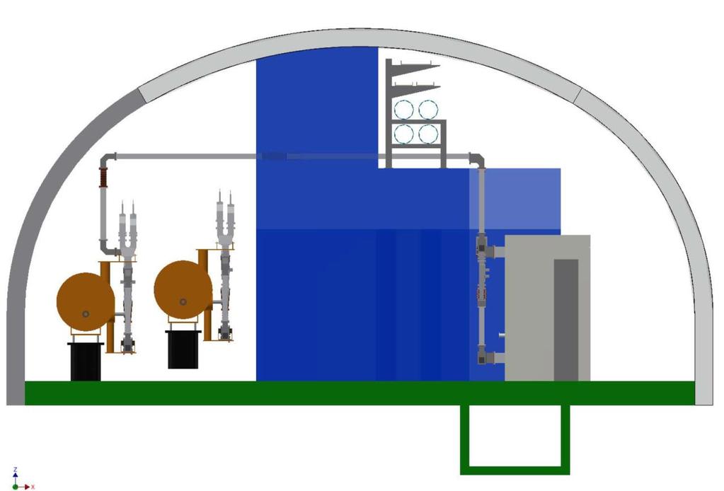
4 Tunnel End View

5 Feeding 3 Stations with 2 Klystrons WR770 used for long runs. Extra 2 3 port network needed at klystron.


6 Standard Waveguide and Waveguide Components Straight sections E-plane and H-plane bends T-splitters and magic T's Semi-flex waveguides folded magic T Need pressurizable and non-pressurizable versions, for stress relief in upper waveguide runs and at cavities.
 Newer model includes forward and reflected pick-ups,")
*.")
7 Isolator and Loads S.P.A. Ferrite, Ltd. (Russia) Newer model includes forward and reflected pick-ups, eliminating the need for a separate bi-directional coupler (reflectometer)*. * But costed as separate components Water cooled (2 types) P pk P av 2 MW 10 kw 5 MW 100 kw


8 SLAC Air-to-Air Window Bi-Directional Couplers (Reflectometers) High power tested up to 3 MW, 1 ms. Ceramic Plug Pressure Window May be largely eliminated by use of isolators with built-in pick-ups.


9 Phase Shifters DESY/SPA Ferrite KEK/Toshiba

10 KEK Variable H-Hybrid (Power Divider) Sergey Kazakov Variable H-hybrid geometry, sample field pattern and in-line port design modification. Moving the two suspended conductors in and out perturbs the relative phase between the two modes supported in the interior section while retaining match, resulting in a varying power split at the output ports.

 = 2")

11 U-Bend Phase Shifter simulation field plot SLAC Variable Power Divider (VPD) = 2 U-bend phase shifters + 2 folded magic-t's C. Nantista
12 XFEL PDS: XFEL Mega: ~ 7K$ / cavity 12
13 ILC PDS: Three kinds of parts: 1. Catalog items (cost basis from Mega/Furukawa; LC=0.95) (modification may be required for pressurization) 2. Loads / Circulators (cost basis SPA Ferrite St. Petersburg; same LC) 3. SLAC / KEK in-house designs with integrated electromechanical actuator; based on WR650 hardware (cost basis from first article; same LC) TDR cost distribution for the above three kinds: 27% 29% 44% (including K-PDS) 13
14 ILC Industrialization Study Part Count -P = pressurizable -NP = non-pressurizable Assume all LPDS s like standard ML klystron feeding 39 cavities: Nc = # of cavities = 16,024 ITEM FORMULA QUANTITY Isolator -NP Nc 16,024 Semi-Flex guide -NP Nc 16,024 Semi-Flex guide -P 3*Nc/13 3,698 Reflectometer -NP Nc 16,024 Reflectometer -P 2*Nc/ Phase Shifter -NP Nc 16,024 Phase Shifter -P Nc/ Pressure window -P 3*Nc/13 3,698 1 MW load -P 3*Nc/13 3,698 5 MW load -P Nc/13 1,233 U-bend Phase Shifter -P 6*Nc/13 7,396 Folded magic-t -P 6*Nc/13 7,396 Variable hybrid -NP 10*Nc/13 12,326 3-dB Hybrid -P Nc/ E-plane shunt T -P Nc/ E-plane bend -P 15*Nc/39 6,163 H-plane bend -P 7*Nc/39 2,876 H-plane bend -NP Nc+3*Nc/13 19,722 E-plane U-bend -NP Nc 16,024 WR converter -P 2*Nc/ WR770 straight 120 -P Nc/ WR650 straight 4 -P 10*Nc/39 4,109 WR650 straight 8 -P 7*Nc/39 2,876 WR650 straight 12 -P 6*Nc/39 2,465 WR650 straight 3 -NP 9*Nc/39 3,698 WR650 straight 8 -NP 27*Nc/39 11,093 Nut/bolt/washers 10*(tot+Nc) 1,918,790
15 Post-TDR MEGA Cost Study Scope Twelve production schemes considered: deliver full, only standard waveguide, only circulators and loads, and only electromechanical devices at 3 varied production levels (25%, 50% and 100%) over a period of 6 years with up to 2 additional years for the following to be completed: a. Casting and extrusion tooling and process development / qualification b. Facility build-out c. Equipment and workstation installation and pre-production verification / release d. Production tooling and process development and qualification The results of this study include plant layouts, time planning for equipment and labor, work flow diagrams, and costs for the industrial components of plan estimated at 2013 prices and rates 15
16 Specific Report Items (1): Plant equipment requirements, including building, technical equipment, and layout of equipment in building. Costs, in 2013 dollars, to create such a facility, and time required to build, prepare, and prove the plant is ready for production. A production plan, including labor and machine hours required. Identification of the top 3 throughput bottlenecks in the plant, and the remedy for each. Analysis of alternatives for each production step, and identification of the top 3 alternatives which should be pursued with R&D to have the greatest economic effect on the production.
17 Specific Report items (2) Identification of components or subcomponents that are prime candidates for subcontracting, including description of existing companies that could fulfill such roles or a description of an industry where such subcontracting should be pursued. Identification of particularly economically burdensome production process requirements or component tolerances which are, and possible remedies for such. Identification of the hub Laboratory contributions, the reasoning for the choice, and a description of the technical criteria that would define such a handoff.
18 Fabrication Tasks Assembly Blending Brazing Manual Mills Clean / Mask Compression Convoluter Copper Plate Electrical Test EMMEGI Final Inspection Forming / Weld Heat Treat In-Process Insp 630 mm HMC 630 mm VMC 1,000 mm HMC Pack / Ship Paint Pressure Test Rinse Router Saws Silver Plate Solder 300 mm Lathe Autowelder TIG Welder

19 Example: TIG Welding

20 The Project Timeline captures the major milestones of the facility build out and ramp up to meet the production demand timeline.
21 Learning Curves The purely mechanical straights and sweeps will quickly hit a production plateau gaining potentially a 10% improvement over time as the workers become more comfortable with the serial production operations and techniques during the first year of production. The more complex components will take significantly more time to attain optimized throughput levels, but we believe a 20% or more improvement may be possible.
22 Top 3 Processes Machining (assumes 85% machinery utilization over two 8 hour shifts per day, five days per week) Welding Testing (to be shared with hub lab) These are also the three potential bottlenecks they identified in particular, in regard to Equipment up time (5% downtime in PY1 and 3% in years PY2 PY6) Employee availability Raw material supply
23 Hub Lab Tasks High power rf testing Electro-mechanical integration (final assembly of subassemblies with motorized drives) Final PDS integration and tuning
24 Possible Improvements Integration of special components Electromechanical devices, typ. SLAC / KEK designs Extrusion Casting Testing automation May provide 20 to 30% cost reduction
25 Summary Industrialization study of non-high-tech components (PDS) completed March 2014 US PDS industry is small-business based Substantial cost-reduction (~1% of ILC total) possible with nominal R&D investment
Next Linear Collider. The 8-Pack Project. 8-Pack Project. Four 50 MW XL4 X-band klystrons installed on the 8-Pack
 The Four 50 MW XL4 X-band klystrons installed on the 8-Pack The Demonstrate an NLC power source Two Phases: 8-Pack Phase-1 (current): Multi-moded SLED II power compression Produce NLC baseline power: 475
Overview of RF Distribution System and Cost Drivers
 Overview of RF Distribution System and Cost Drivers For Snowmass 2005 WG 2 Brian Rusnak Lawrence Livermore National Laboratory *This work was performed under the auspices of the U. S. Department of Energy
INFN School on Electron Accelerators. RF Power Sources and Distribution
 INFN School on Electron Accelerators 12-14 September 2007, INFN Sezione di Pisa Lecture 7b RF Power Sources and Distribution Carlo Pagani University of Milano INFN Milano-LASA & GDE The ILC Double Tunnel
WG2 Group Summary. Chris Adolphsen Terry Garvey Hitoshi Hayano
 WG2 Group Summary Chris Adolphsen Terry Garvey Hitoshi Hayano Linac Options Fest On Thursday afternoon, various experts summarized the linac baseline options. Although hard choices have yet to be made,
Detailed Design Report
 Detailed Design Report Chapter 4 MAX IV Injector 4.6. Acceleration MAX IV Facility CHAPTER 4.6. ACCELERATION 1(10) 4.6. Acceleration 4.6. Acceleration...2 4.6.1. RF Units... 2 4.6.2. Accelerator Units...
XFEL High Power RF System Recent Developments
 XFEL High Power RF System Recent Developments for the XFEL RF Group Outline XFEL RF System Requirements Overview Basic Layout RF System Main Components Multibeam Klystrons Modulator RF Waveguide Distribution
3 cerl. 3-1 cerl Overview. 3-2 High-brightness DC Photocathode Gun and Gun Test Beamline
 3 cerl 3-1 cerl Overview As described before, the aim of the cerl in the R&D program includes the development of critical components for the ERL, as well as the construction of a test accelerator. The
ILC-LNF TECHNICAL NOTE
 IL-LNF EHNIAL NOE Divisione Acceleratori Frascati, July 4, 2006 Note: IL-LNF-001 RF SYSEM FOR HE IL DAMPING RINGS R. Boni, INFN-LNF, Frascati, Italy G. avallari, ERN, Geneva, Switzerland Introduction For
45 MW, 22.8 GHz Second-Harmonic Multiplier for High-Gradient Tests*
 US High Gradient Research Collaboration Workshop. SLAC, May 23-25, 2007 45 MW, 22.8 GHz Second-Harmonic Multiplier for High-Gradient Tests* V.P. Yakovlev 1, S.Yu. Kazakov 1,2, and J.L. Hirshfield 1,3 1
5 Project Costs and Schedule
 93 5 Project Costs and Schedule 5.1 Overview The cost evaluation for the integrated version of the XFEL with 30 experiments and 35 GeV beam energy as described in the TDR-2001 yielded 673 million EUR for
Nick Walker DESY MAC
 Nick Walker DESY MAC 4.5.2006 XFEL X-Ray Free-Electron Laser DESY ILC Project Group Accelerator Experimentation Behnke, Elsen, Walker (chair) WP 15, 16 WP 4-7 Accelerator Physics and Design WP 6 High Gradient
RF Upgrades & Experience At JLab. Rick Nelson
 RF Upgrades & Experience At JLab Rick Nelson Outline Background: CEBAF / Jefferson Lab History, upgrade requirements & decisions Progress & problems along the way Present status Future directions & concerns
A New 4MW LHCD System for EAST
 1 EXW/P7-29 A New 4MW LHCD System for EAST Jiafang SHAN 1), Yong YANG 1), Fukun LIU 1), Lianmin ZHAO 1) and LHCD Team 1) 1) Institute of Plasma Physics, Chinese Academy of Sciences, Hefei, China E-mail
Pulsed Klystrons for Next Generation Neutron Sources Edward L. Eisen - CPI, Inc. Palo Alto, CA, USA
 Pulsed Klystrons for Next Generation Neutron Sources Edward L. Eisen - CPI, Inc. Palo Alto, CA, USA Abstract The U.S. Department of Energy (DOE) Office of Science has funded the construction of a new accelerator-based
DEVELOPMENT OF A 10 MW SHEET BEAM KLYSTRON FOR THE ILC*
 DEVELOPMENT OF A 10 MW SHEET BEAM KLYSTRON FOR THE ILC* D. Sprehn, E. Jongewaard, A. Haase, A. Jensen, D. Martin, SLAC National Accelerator Laboratory, Menlo Park, CA 94020, U.S.A. A. Burke, SAIC, San
L-Band RF R&D. SLAC DOE Review June 15 th, Chris Adolphsen SLAC
 L-Band RF R&D SLAC DOE Review June 15 th, 2005 Chris Adolphsen SLAC International Linear Collider (ILC) RF Unit (TESLA TDR Layout) Gradient = 23.4 MV/m Bunch Spacing = 337 ns Fill Time = 420 µs Train Length
Oak Ridge Spallation Neutron Source Proton Power Upgrade Project and Second Target Station Project
 Oak Ridge Spallation Neutron Source Proton Power Upgrade Project and Second Target Station Project Workshop on the future and next generation capabilities of accelerator driven neutron and muon sources
J/NLC Progress on R1 and R2 Issues. Chris Adolphsen
 J/NLC Progress on R1 and R2 Issues Chris Adolphsen Charge to the International Linear Collider Technical Review Committee (ILC-TRC) To assess the present technical status of the four LC designs at hand,
LCLS RF Reference and Control R. Akre Last Update Sector 0 RF and Timing Systems
 LCLS RF Reference and Control R. Akre Last Update 5-19-04 Sector 0 RF and Timing Systems The reference system for the RF and timing starts at the 476MHz Master Oscillator, figure 1. Figure 1. Front end
The LEP Superconducting RF System
 The LEP Superconducting RF System K. Hübner* for the LEP RF Group CERN The basic components and the layout of the LEP rf system for the year 2000 are presented. The superconducting system consisted of
Experience with the Cornell ERL Injector SRF Cryomodule during High Beam Current Operation
 Experience with the Cornell ERL Injector SRF Cryomodule during High Beam Current Operation Matthias Liepe Assistant Professor of Physics Cornell University Experience with the Cornell ERL Injector SRF
PEP-II Overview & Ramp Down Plan. J. Seeman DOE PEP-II Ramp Down-D&D Review August 6-7, 2007
 PEP-II Overview & Ramp Down Plan J. Seeman DOE PEP-II Ramp Down-D&D Review August 6-7, 2007 Topics Overview of the PEP-II Collider PEP-II turns off September 30, 2008. General list of components and buildings
Present Status and Future Upgrade of KEKB Injector Linac
 Present Status and Future Upgrade of KEKB Injector Linac Kazuro Furukawa, for e /e + Linac Group Present Status Upgrade in the Near Future R&D towards SuperKEKB 1 Machine Features Present Status and Future
Availability and Reliability Issues for the ILC
 Availability and Reliability Issues for the ILC SLAC Presented at PAC07 26 June 07 Contents Introduction and purpose of studies The availability simulation What was modeled (important assumptions) Some
2 Work Package and Work Unit descriptions. 2.8 WP8: RF Systems (R. Ruber, Uppsala)
") 2 Work Package and Work Unit descriptions 2.8 WP8: RF Systems (R. Ruber, Uppsala) The RF systems work package (WP) addresses the design and development of the RF power generation, control and distribution
2 Work Package and Work Unit descriptions 2.8 WP8: RF Systems (R. Ruber, Uppsala) The RF systems work package (WP) addresses the design and development of the RF power generation, control and distribution
RF considerations for SwissFEL
 RF considerations for H. Fitze in behalf of the PSI RF group Workshop on Compact X-Ray Free Electron Lasers 19.-21. July 2010, Shanghai Agenda Introduction RF-Gun Development C-band development Summary
TITLE PAGE. Title of paper: PUSH-PULL FEL, A NEW ERL CONCEPT Author: Andrew Hutton. Author Affiliation: Jefferson Lab. Requested Proceedings:
 TITLE PAGE Title of paper: PUSH-PULL FEL, A NEW ERL CONCEPT Author: Andrew Hutton Author Affiliation: Jefferson Lab Requested Proceedings: Unique Session ID: Classification Codes: Keywords: Energy Recovery,
CLIC Feasibility Demonstration at CTF3
 CLIC Feasibility Demonstration at CTF3 Roger Ruber Uppsala University, Sweden, for the CLIC/CTF3 Collaboration http://cern.ch/clic-study LINAC 10 MO303 13 Sep 2010 The Key to CLIC Efficiency NC Linac for
X-Band Klystron Development at
 X-Band Klystron Development at SLAC Slide 1 The Beginning X-band klystron work began at SLAC in the mid to late 80 s to develop high frequency (4x SLAC s-band), high power RF sources for the linear collider
DELIVERY RECORD. Location: Ibaraki, Japan
 DELIVERY RECORD Client: Japan Atomic Energy Agency (JAEA) High Energy Accelerator Research Organization (KEK) Facility: J-PARC (Japan Proton Accelerator Research Complex) Location: Ibaraki, Japan 1 October
!"!3
 Abstract A single-mode 500 MHz superconducting cavity cryomodule has been developed at Cornell for the electronpositron collider/synchrotron light source CESR. The Cornell B-cell cavity belongs to the
Spear3 RF System Sam Park 11/06/2003. Spear3 RF System. High Power Components Operation and Control. RF Requirement.
 Spear3 RF System RF Requirement Overall System High Power Components Operation and Control SPEAR 3 History 1996 Low emittance lattices explored 1996 SPEAR 3 proposed 11/97 SPEAR 3 design study team formed
Development of Multiple Beam Guns for High Power RF Sources for Accelerators and Colliders
 SLAC-PUB-10704 Development of Multiple Beam Guns for High Power RF Sources for Accelerators and Colliders R. Lawrence Ives*, George Miram*, Anatoly Krasnykh @, Valentin Ivanov @, David Marsden*, Max Mizuhara*,
OF THIS DOCUMENT IS W8.MTO ^ SF6
 fflgh PEAK POWER TEST OF S-BAND WAVEGUIDE SWITCHES A. Nassiri, A. Grelick, R. L. Kustom, and M. White CO/0 ^"^J} 5, t * y ^ * Advanced Photon Source, Argonne National Laboratory» \^SJ ^ ^ * **" 9700 South
 STF Beta
 STATUS OF THE SWISSFEL C-BAND LINEAR ACCELERATOR
 Proceedings of FEL213, New York, NY, USA STATUS OF THE SWISSFEL C-BAND LINEAR ACCELERATOR F. Loehl, J. Alex, H. Blumer, M. Bopp, H. Braun, A. Citterio, U. Ellenberger, H. Fitze, H. Joehri, T. Kleeb, L.
Evaluation of Performance, Reliability, and Risk for High Peak Power RF Sources from S-band through X-band for Advanced Accelerator Applications
 Evaluation of Performance, Reliability, and Risk for High Peak Power RF Sources from S-band through X-band for Advanced Accelerator Applications Michael V. Fazio C. Adolphsen, A. Jensen, C. Pearson, D.
ILC RF System R&D. Chris Adolphsen, SLAC. Section of 1.3 GHz SC Linac. June 29, 2007 PAC07 Talk FRYC01
 ILC RF System R&D Chris Adolphsen, SLAC June 29, 2007 PAC07 Talk FRYC01 Section of 1.3 GHz SC Linac ILC Main Linac RF Unit (1 of 560) RF System Gradient = 31.5 MV/m Rep Rate = 5 Hz Beam Current = 9.0 ma
Towards an X-Band Power Source at CERN and a European Structure Test Facility
 Towards an X-Band Power Source at CERN and a European Structure Test Facility Erk Jensen and Gerry McMomagle CERN The X-Band Accelerating Structure Design and Test-Program Workshop Day 2: Structure Testing
Status of BESSY II and berlinpro. Wolfgang Anders. Helmholtz-Zentrum Berlin for Materials and Energy (HZB) 20th ESLS-RF Meeting
 20th ESLS-RF Meeting") Status of BESSY II and berlinpro Wolfgang Anders Helmholtz-Zentrum Berlin for Materials and Energy (HZB) 20th ESLS-RF Meeting 16.-17.11.2016 at PSI Outline BESSY II Problems with circulators Landau cavity
Status of BESSY II and berlinpro Wolfgang Anders Helmholtz-Zentrum Berlin for Materials and Energy (HZB) 20th ESLS-RF Meeting 16.-17.11.2016 at PSI Outline BESSY II Problems with circulators Landau cavity
RF Power Upgrade at Jefferson Lab
 RF Power Upgrade at Jefferson Lab Rick Nelson*, Andrew Kimber *nelson@jlab.org * Notice: Authored by Jefferson Science Associates, LLC under U.S. DOE Contract No. DE- AC05-06OR23177. The U.S. Government
DEPARTMENT OF ELECTRONICS AND COMMUNICATION ENGINEERING QUESTION BANK
 DEPARTMENT OF ELECTRONICS AND COMMUNICATION ENGINEERING QUESTION BANK SUBJECT NAME : MICROWAVE ENGINEERING UNIT I BASIC MICROWAVE COMPONENTS 1. State Faraday s rotation law. 2. State the properties of
SPS BPM system renovation. Roadmap & Milestones
 SPS BPM system renovation Roadmap & Milestones Synopsis Introduction and Overview: Andrea Infrastructures Fibres: Simao Cables: Joel Electronics Analogue Front-End: Manfred Digital Front-End: Manoel Back-End:
STATUS OF THE INTERNATIONAL LINEAR COLLIDER
 STATUS OF THE INTERNATIONAL LINEAR COLLIDER K. Yokoya, KEK, Tsukuba, Japan Abstract The International Linear Collider (ILC) is the nextgeneration electron-positron collider. Since the publication of the
SUMMARY OF THE ILC R&D AND DESIGN
 SUMMARY OF THE ILC R&D AND DESIGN B. C. Barish, California Institute of Technology, USA Abstract The International Linear Collider (ILC) is a linear electron-positron collider based on 1.3 GHz superconducting
DEVELOPMENT OF X-BAND KLYSTRON TECHNOLOGY AT SLAC
 DEVELOPMENT OF X-BAND KLYSTRON TECHNOLOGY AT SLAC George Caryotakis, Stanford Linear Accelerator Center P.O. Box 4349 Stanford, CA 94309 Abstract * The SLAC design for a 1-TeV collider (NLC) requires klystrons
Examples of Successful Collaboration Between CPI and DOE Labs. Todd Treado CPI December 2013
 Examples of Successful Collaboration Between CPI and DOE Labs Todd Treado CPI December 2013 Overview CPI has successfully collaborated with US DOE labs to develop and / or manufacture products for DOE
MPI Cable Selection Guide
 MPI Cable Selection Guide MPI engineers focus to provide on optimal cable solutions taking into account a number of requirements specific for wafer-level measurement systems: optimal cable length, cable
Thoughts on Project Standard in Japan
 Thoughts on Project Standard in Japan August 16, 2005 H. Hayano, KEK Thoughts on project standard in Japan Production is industry-base, almost all-case. 1. Industry makes every detail drawings. 2. (Big)
North Damping Ring RF
 North Damping Ring RF North Damping Ring RF Outline Overview High Power RF HVPS Klystron & Klystron EPICS controls Cavities & Cavity Feedback SCP diagnostics & displays FACET-specific LLRF LLRF distribution
ADE-R3GLH+ CONVERSION LOSS 50. ISOLATION (db) 10 LO= +7 dbm LO= +10 dbm LO=+13 dbm FREQUENCY (MHz) RF VSWR
 10 LO= +7 dbm LO= +10 dbm LO=+13 dbm FREQUENCY (MHz) RF VSWR") Surface Mount High Reliability Mixer Level 10 ( Power +10 dbm) 2000 to 2700 MHz Maximum Ratings Operating Temperature -40 C to 85 C Storage Temperature -55 C to 100 C RF Power 50mW IF Current 40mA Permanent
Surface Mount High Reliability Mixer Level 10 ( Power +10 dbm) 2000 to 2700 MHz Maximum Ratings Operating Temperature -40 C to 85 C Storage Temperature -55 C to 100 C RF Power 50mW IF Current 40mA Permanent
ILC Damping Ring Lattice Status Report. Louis Emery and Aimin Xiao Argonne National Laboratory Presented at KEK workshop Dec 18th, 2007
 Status Report Louis Emery and Aimin Xiao Argonne National Laboratory Presented at KEK workshop Dec 18th, 2007 Outline New 8-fold symmetric lattice on ILC Cornell wiki pages, as of 12/18/2007 Separated
White Paper. Performance analysis: DOCSIS 3.1 cable TV headend combining systems
 Performance analysis: DOCSIS 3.1 cable TV headend combining systems Measuring MER performance of QAM signals in passive & active combining systems White Paper Practical splitter performance Introduction
SPINNER BROADCAST EXPLANATION OF THE MULTI CHANNEL COMBINER SPECIFICATIONS
 EXPLANATION OF THE MULTI CHANNEL COMBINER SPECIFICATIONS Calculation of the maximum permissible output voltage Various signals are added up within the combiner. The peak voltages of the individual signal
PoS(EPS-HEP2015)525. The RF system for FCC-ee. A. Butterworth CERN 1211 Geneva 23, Switzerland
525. The RF system for FCC-ee. A. Butterworth CERN 1211 Geneva 23, Switzerland") CERN 1211 Geneva 23, Switzerland E-mail: andrew.butterworth@cern.ch O. Brunner CERN 1211 Geneva 23, Switzerland E-mail: olivier.brunner@cern.ch R. Calaga CERN 1211 Geneva 23, Switzerland E-mail: rama.calaga@cern.ch
CERN 1211 Geneva 23, Switzerland E-mail: andrew.butterworth@cern.ch O. Brunner CERN 1211 Geneva 23, Switzerland E-mail: olivier.brunner@cern.ch R. Calaga CERN 1211 Geneva 23, Switzerland E-mail: rama.calaga@cern.ch
Suggested ILC Beam Parameter Range Rev. 2/28/05 Tor Raubenheimer
 The machine parameters and the luminosity goals of the ILC were discussed at the 1 st ILC Workshop. In particular, Nick Walker noted that the TESLA machine parameters had been chosen to achieve a high
Pulses inside the pulse mode of operation at RF Gun
 Pulses inside the pulse mode of operation at RF Gun V. Vogel, V. Ayvazyan, K. Floettmann, D. Lipka, P. Morozov, H. Schlarb, S. Schreiber FLASH Seminar, DESY March 29, 2011 Contents Why we need a PiPmode
Karin Rathsman. Calculations on the RF Source and Distribution
 Accelerator Division ESS AD Technical Note ESS/AD/0002 Karin Rathsman Calculations on the RF Source and Distribution 26 March 2010 Calculations on the rf source and distribution system for the ESS elliptical
STATUS OF THE SwissFEL C-BAND LINAC
 STATUS OF THE SwissFEL C-BAND LINAC F. Loehl, J. Alex, H. Blumer, M. Bopp, H. Braun, A. Citterio, U. Ellenberger, H. Fitze, H. Joehri, T. Kleeb, L. Paly, J.-Y. Raguin, L. Schulz, R. Zennaro, C. Zumbach,
High Brightness Injector Development and ERL Planning at Cornell. Charlie Sinclair Cornell University Laboratory for Elementary-Particle Physics
 High Brightness Injector Development and ERL Planning at Cornell Charlie Sinclair Cornell University Laboratory for Elementary-Particle Physics June 22, 2006 JLab CASA Seminar 2 Background During 2000-2001,
Features. = +25 C, IF = 1 GHz, LO = +13 dbm*
 v.5 HMC56LM3 SMT MIXER, 24-4 GHz Typical Applications Features The HMC56LM3 is ideal for: Test Equipment & Sensors Point-to-Point Radios Point-to-Multi-Point Radios Military & Space Functional Diagram
PEP II STATUS AND PLANS *
 PEP II STATUS AND PLANS * John T. Seeman + Stanford Linear Accelerator Center, Stanford University, Stanford, CA 94309 USA The PEP II B-Factory 1 project is an e + e - colliding beam storage ring complex
Commissioning of Accelerators. Dr. Marc Munoz (with the help of R. Miyamoto, C. Plostinar and M. Eshraqi)
") Commissioning of Accelerators Dr. Marc Munoz (with the help of R. Miyamoto, C. Plostinar and M. Eshraqi) www.europeanspallationsource.se 6 July, 2017 Contents General points Definition of Commissioning
Commissioning of Accelerators Dr. Marc Munoz (with the help of R. Miyamoto, C. Plostinar and M. Eshraqi) www.europeanspallationsource.se 6 July, 2017 Contents General points Definition of Commissioning
A HIGH POWER LONG PULSE HIGH EFFICIENCY MULTI BEAM KLYSTRON
 A HIGH POWER LONG PULSE HIGH EFFICIENCY MULTI BEAM KLYSTRON A.Beunas and G. Faillon Thales Electron Devices, Vélizy, France S. Choroba DESY, Hamburg, Germany Abstract THALES ELECTRON DEVICES has developed
PEP II Status and Plans
 SLAC-PUB-6854 September 1998 PEP II Status and Plans By John T. Seeman Invited talk presented at the 16th IEEE Particle Accelerator Conference (PAC 95) and International Conference on High Energy Accelerators,
Status of SOLARIS. Paweł Borowiec On behalf of Solaris Team
 Status of SOLARIS Paweł Borowiec On behalf of Solaris Team e-mail: pawel.borowiec@uj.edu.pl XX ESLS-RF Meeting, Villingen 16-17.11.2016 Outline 1. Timeline 2. Injector 3. Storage ring 16-17.11.2016 XX
DESIGN AND PERFORMANCE OF L-BAND AND S-BAND MULTI BEAM KLYSTRONS
 DESIGN AND PERFORMANCE OF L-BAND AND S-BAND MULTI BEAM KLYSTRONS Y. H. Chin, KEK, Tsukuba, Japan. Abstract Recently, there has been a rising international interest in multi-beam klystrons (MBK) in the
Upgrade of CEBAF to 12 GeV
 Upgrade of CEBAF to 12 GeV Leigh Harwood (for 12 GeV Accelerator team) Page 1 Outline Background High-level description Schedule Sub-system descriptions and status Summary Page 2 CEBAF Science Mission
Design, Fabrication and Testing of Gun-Collector Test Module for 6 MW Peak, 24 kw Average Power, S-Band Klystron
 Available online www.ejaet.com European Journal of Advances in Engineering and Technology, 2014, 1(1): 11-15 Research Article ISSN: 2394-658X Design, Fabrication and Testing of Gun-Collector Test Module
Modulator Overview System Design vs. Tunnel Topologies. Snowmass Workshop August 16, 2005 Ray Larsen for the SLAC ILC Group
 Modulator Overview System Design vs. Tunnel Topologies Snowmass Workshop August 16, 2005 Ray Larsen for the SLAC ILC Group Outline! I. Modulator Options vs. Topologies! II. Preliminary Cost Estimates!
The FLASH objective: SASE between 60 and 13 nm
 Injector beam control studies winter 2006/07 talk from E. Vogel on work performed by W. Cichalewski, C. Gerth, W. Jalmuzna,W. Koprek, F. Löhl, D. Noelle, P. Pucyk, H. Schlarb, T. Traber, E. Vogel, FLASH
Status of CTF3. G.Geschonke CERN, AB
 Status of CTF3 G.Geschonke CERN, AB CTF3 layout CTF3 - Test of Drive Beam Generation, Acceleration & RF Multiplication by a factor 10 Drive Beam Injector ~ 50 m 3.5 A - 2100 b of 2.33 nc 150 MeV - 1.4
Features low conversion loss, 6.11 db typ. excellent L-R isolation, 44 db typ. CONVERSION LOSS (db) Mid-Band m. Range f L. Conversion Loss (db)
 Mid-Band m. Range f L. Conversion Loss (db)") Surface Mount Level 13 ( Power +13dBm) 2 to 500 MHz Maximum Ratings Operating Temperature -40 C to 85 C Storage Temperature -55 C to 100 C RF Power Pin Connections 1 RF 4 IF 5 GROUND 2,3,6 Outline Drawing
Surface Mount Level 13 ( Power +13dBm) 2 to 500 MHz Maximum Ratings Operating Temperature -40 C to 85 C Storage Temperature -55 C to 100 C RF Power Pin Connections 1 RF 4 IF 5 GROUND 2,3,6 Outline Drawing
Accelerator Instrumentation RD. Monday, July 14, 2003 Marc Ross
 Monday, Marc Ross Linear Collider RD Most RD funds address the most serious cost driver energy The most serious impact of the late technology choice is the failure to adequately address luminosity RD issues
Frequency Mixer wide band
 High IP3 Frequency Mixer wide band Level 13 ( Power+13 dbm) 500 to 3500 MHz Maximum Ratings Operating Temperature -55 C to 100 C Storage Temperature -55 C to 100 C RF Power IF Current Pin Connections 200
MAMX Sub-Harmonic Pumped Mixer GHz Rev. V1. Functional Schematic. Features. Description. Pin Configuration 1
 MAMX-119 Features Up or Down Frequency Mixer Low Conversion Loss: 11 db 2xLO & 3xLO Rejection: db RF Frequency: 14 - LO Frequency: 4-2 GHz IF Frequency: DC - 7 GHz Lead-Free 1.x1.2 mm 6-lead TDFN Package
News from HZB / BESSY Wolfgang Anders at ESLS-RF Meeting September 2010 Trieste
 News from HZB / BESSY Wolfgang Anders at ESLS-RF Meeting September 2010 Trieste Outline Status Klystrons / IOT Modifications of transmitters New LINAC for BESSY II Status BERLinPro HoBiCaT Extension --
Features low conversion loss, 5.94 db typ. aqueous washable J-leads for strain relief. CONVERSION LOSS (db) Mid-Band m. Range f L.
 Mid-Band m. Range f L.") Surface Mount Frequency Mixer Level 7 ( Power +7dBm) 0.5 to 500 MHz Maximum Ratings Operating Temperature -40 C to 85 C Storage Temperature -55 C to 100 C RF Power Pin Connections 1 RF 4 IF 5 GROUND 2,3,6
Surface Mount Frequency Mixer Level 7 ( Power +7dBm) 0.5 to 500 MHz Maximum Ratings Operating Temperature -40 C to 85 C Storage Temperature -55 C to 100 C RF Power Pin Connections 1 RF 4 IF 5 GROUND 2,3,6
NSLS-II RF Systems James Rose, Radio Frequency Group Leader PAC 2011
 NSLS-II RF Systems James Rose, Radio Frequency Group Leader PAC 2011 1 BROOKHAVEN SCIENCE ASSOCIATES Introduction Linac RF cavities and klystrons Booster Cavity-Transmitter Storage Ring 500 MHz SRF cavity
Welcome and FRIB Project Status. FRIB Highlights and Plan Ahead
 Welcome and FRIB Project Status Thomas Glasmacher Project Manager This material is based upon work supported by the U.S. Department of Energy Office of Science under Cooperative Agreement DE-SC0000661.
CEBAF 8 kw CW KLYSTRON SPECIFICATION EE0043, Rev. H January 15, 1998
 Thomas Jefferson National Laboratory Specification CEBAF 8 kw CW KLYSTRON SPECIFICATION EE0043, Rev. H January 15, 1998 Approved by: Richard Nelson Date William Merz Date Claus Rode Date EE0044, Rev. H
RF Design of the LCLS Gun C.Limborg, Z.Li, L.Xiao, J.F. Schmerge, D.Dowell, S.Gierman, E.Bong, S.Gilevich February 9, 2005
 RF Design of the LCLS Gun C.Limborg, Z.Li, L.Xiao, J.F. Schmerge, D.Dowell, S.Gierman, E.Bong, S.Gilevich February 9, 2005 Summary Final dimensions for the LCLS RF gun are described. This gun, referred
Hitachi Kokusai Electric Comark LLC
 Hitachi Kokusai Electric Comark LLC TRANSMIT TER OF THE FUTURE Solid State. Broadband. Affordable. The future has arrived. With rapid changes in solid state RF device technologies and design techniques,
A Cathode Development Cornell Cultera This scope includes all labor and purchases required produce photocathodes required by CBETA.
 A1.01 PROJECT MANAGEMENT BNL/Cornell Michnoff A1.01.01 Milestones BNL/Cornell Michnoff This scope is a placeholder for all project high level milestones for NYSERDA. There is no cost or labor related to
Summary of the 1 st Beam Line Review Meeting Injector ( )
") Summary of the 1 st Beam Line Review Meeting Injector (23.10.2006) 15.11.2006 Review the status of: beam dynamics understanding and simulations completeness of beam line description conceptual design of
Summary of the 1 st Beam Line Review Meeting Injector (23.10.2006) 15.11.2006 Review the status of: beam dynamics understanding and simulations completeness of beam line description conceptual design of
Studies on an S-band bunching system with hybrid buncher
 Submitted to Chinese Physics C Studies on an S-band bunching system with hybrid buncher PEI Shi-Lun( 裴士伦 ) 1) XIAO Ou-Zheng( 肖欧正 ) Institute of High Energy Physics, Chinese Academy of Sciences, Beijing
Axle Assembly Poke-Yoke
 Indiana University Purdue University Fort Wayne Opus: Research & Creativity at IPFW Manufacturing & Construction Engineering Technology and Interior Design Senior Design Projects School of Engineering,
LAVI-U252VH+ Performance Charts. LO=+18dBm LO=+21dBm LO=+24dBm. LO=+18dBm LO=+21dBm LO=+24dBm. LO=+18dBm LO=+21dBm LO=+24dBm
 Up Converter Frequency Mixer Level 21 ( Power +21 dbm) 10 to 2500 MHz Maximum Ratings Operating Temperature -45 C to 85 C Storage Temperature -55 C to 100 C Power Pin Connections +24 dbm IF Power +21 dbm
Karin Rathsman, Håkan Danared and Rihua Zeng. Report from RF Power Source Workshop
 Accelerator Division ESS AD Technical Note ESS/AD/0020 Karin Rathsman, Håkan Danared and Rihua Zeng Report from RF Power Source Workshop 10 July 2011 Report on the RF Power Source Workshop K. Rathsman,
TOSHIBA Industrial Magnetron E3328
 TOSHIBA E3328 is a fixed frequency continuous wave magnetron intended for use in the industrial microwave heating applications. The average output power is 3kW in the frequency range from 2450 to 2470
The PEFP 20-MeV Proton Linear Accelerator
 Journal of the Korean Physical Society, Vol. 52, No. 3, March 2008, pp. 721726 Review Articles The PEFP 20-MeV Proton Linear Accelerator Y. S. Cho, H. J. Kwon, J. H. Jang, H. S. Kim, K. T. Seol, D. I.
ANKA RF System - Upgrade Strategies
 ANKA RF System - Upgrade Strategies Vitali Judin ANKA Synchrotron Radiation Facility 2014-09 - 17 KIT University of the State Baden-Wuerttemberg and National Laboratory of the Helmholtz Association www.kit.edu
Features excellent conversion loss, 6.0 db typ. high L-R isolation, 40 db typ. L-I isolation, 55 db typ. rugged welded construction
 Plug-In NON-CATAG Level 10 ( Power +10 dbm) 10 to 1000 MHz Maximum Ratings Operating Temperature -55 C to 100 C Storage Temperature -55 C to 100 C RF Power Pin Connections 8 RF 3,4^ IF 1 GROUND 2,5,6,7
ARES Status 2004(JFY)
") ARES Status 2004(JFY) Tetsuo Abe for KEKB-RF/ARES-cavity group High Energy Accelerator Research Organization (KEK) Outline 1. Fundamentals of the ARES-cavity system 2. Operation status 3. D04C/ARES multipactoring
ARES Status 2004(JFY) Tetsuo Abe for KEKB-RF/ARES-cavity group High Energy Accelerator Research Organization (KEK) Outline 1. Fundamentals of the ARES-cavity system 2. Operation status 3. D04C/ARES multipactoring
Dark current and multipacting trajectories simulations for the RF Photo Gun at PITZ
 Dark current and multipacting trajectories simulations for the RF Photo Gun at PITZ Introduction The PITZ RF Photo Gun Field simulations Dark current simulations Multipacting simulations Summary Igor Isaev
Low Level RF for PIP-II. Jonathan Edelen LLRF 2017 Workshop (Barcelona) 16 Oct 2017
 16 Oct 2017") Low Level RF for PIP-II Jonathan Edelen LLRF 2017 Workshop (Barcelona) 16 Oct 2017 PIP-II LLRF Team Fermilab Brian Chase, Edward Cullerton, Joshua Einstein, Jeremiah Holzbauer, Dan Klepec, Yuriy Pischalnikov,
Low Level RF for PIP-II Jonathan Edelen LLRF 2017 Workshop (Barcelona) 16 Oct 2017 PIP-II LLRF Team Fermilab Brian Chase, Edward Cullerton, Joshua Einstein, Jeremiah Holzbauer, Dan Klepec, Yuriy Pischalnikov,
Operating Experience and Reliability Improvements on the 5 kw CW Klystron at Jefferson Lab
 Operating Experience and Reliability Improvements on the 5 kw CW Klystron at Jefferson Lab Richard Walker & Richard Nelson Jefferson Lab, Newport News VA Jefferson Lab is a $600M Department of Energy facility
TEST RESULTS OF THE 84 GHZ / 200 KW / CW GYROTRON
 TEST RESULTS OF THE 84 GHZ / 200 KW / CW GYROTRON V.I. Belousov, A.A.Bogdashov, G.G.Denisov, V.I.Kurbatov, V.I.Malygin, S.A.Malygin, V.B.Orlov, L.G.Popov, E.A.Solujanova, E.M.Tai, S.V.Usachov Gycom Ltd,
Monthly Progress Report Stanford Synchrotron Radiation Laboratory
 Monthly Progress Report Stanford Synchrotron Radiation Laboratory April 2003 TABLE OF CONTENTS A. Project Summary 1. Technical Progress 3 2. Cost Data 5 B. Design and Fabrication Reports 1.1 Magnets &
Mechanical aspects, FEA validation and geometry optimization
 RF Fingers for the new ESRF-EBS EBS storage ring The ESRF-EBS storage ring features new vacuum chamber profiles with reduced aperture. RF fingers are a key component to ensure good vacuum conditions and