7 N. F v : average latching force (without contact) 110 N. F a : average retention force (without contact) 9 N
|
|
|
- Daniella Fowler
- 5 years ago
- Views:
Transcription
1 PLASTIC CONNECTORS
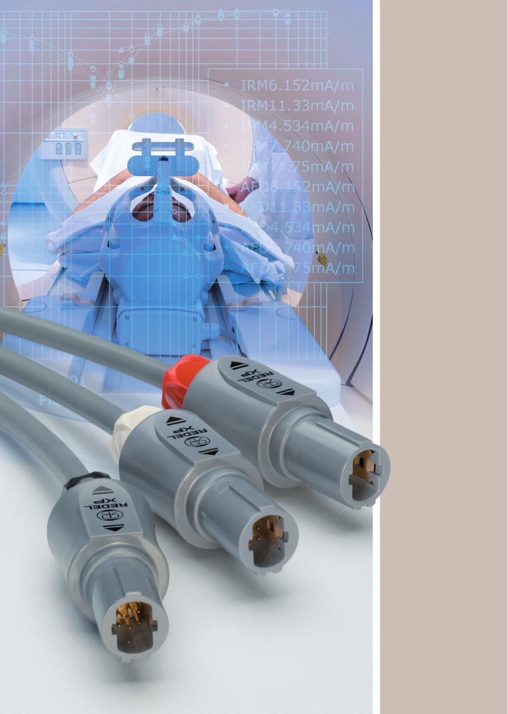
2 Precision modular connectors to suit your application Since its creation in Switzerland in 1946 the LEMO Group has been recognized as a global leader of circular Push-Pull connectors and connector solutions. Today LEMO and its affiliated companies, REDEL and COELVER, are active in more than 8 countries with the help of over 4 subsidiaries and distributors. Over 5 REDEL connectors The modular design of the REDEL range provides over 5 connectors from ø 14 mm to ø 21 mm, capable of handling cable diameters up to 9.5 mm and up to 32 contacts. This vast portfolio enables you to select the ideal connector configuration to suit almost any specific requirement in most markets, including medical devices, test and measurement instruments, machinery, audio video broadcast, telecommunications and military. REDEL s Push-Pull Self-Latching Connection System This self-latching system is renowned worldwide for its easy and quick mating and unmating features. It provides absolute security against vibration, shock or pull on the cable, and facilitates operation in a very limited space. F v 7 N The REDEL self-latching system allows the connector to be mated by simply pushing the plug axially into the socket. F v : average latching force (without contact) F a 11 N Once firmly latched, connection cannot be broken by pulling on the cable or any other component part other than the outer release sleeve. F a : average retention force (without contact) F d 9 N When required, the connector is disengaged by a single axial pull on the outer release sleeve. This first disengages the latches and then withdraws the plug from the socket. F d : average unmating force (without contact) UL Recognition REDEL connectors are recognized by the Underwriters Laboratories (UL). The approval of the complete system (REDEL connector, cable and your equipment) will be easier because REDEL connectors are approved. CE Marking CE marking means that the appliance or equipment bearing it complies with the protection requirements of one or several European safety directives. CE marking applies to complete products or equipment, but not to electromechanical components, such as connectors. RoHS REDEL connector specifications exceed the requirements of the RoHS directives (22/95/EC) of the European Parliament and the latest amendments. This directive specifies the restrictions of the use of hazardous substances in electrical and electronic equipment marketed in Europe. LEMO guarantees that its connectors are free of mercury, cadmium, lead, hexavalent chromium and polybromide biphenyl (PBB), polybromide diphenyl ether (PBDE), or DecaBDE. Cover picture: PET-IRM scanner installed in Hôpitaux Universitaires de Genève (Switzerland).

3 Exploded view of the REDEL XP Straight plug backnut cable collet insulator + contacts shell Straight plug with bend relief backnut for bend relief a bend relief cable collet insulator + contacts shell Fixed socket collet nut notched nut insulator + contacts shell front nut Free socket backnut cable collet insulator + contacts shell 1
4 XP Series The REDEL XP connectors are plastic Push-Pull connectors. These circular plastic connectors are especially adapted for applications such as medical electronics and test & measurement. The XP series offer additional features: the latch sleeve is recessed into the connector body ensuring greater shock resistance of the product. The complete connector can be assembled from spare parts (even the contact configuration) therefore offering good flexibility in stock keeping. The outer shell in Proprietary sulfone enables extensive sterilisation cycles of the product. A large choice of bend relief is available in different colour and size. REDEL XP series connectors are not compatible with the REDEL 1P or 2P series. Features & Benefits Applications Plastic shell made of Proprietary sulfone Medical electronics Blind mating, scoop proof Test & measurement Extended resistance to sterilisation Industrial electronics Enhanced ergonomics «hand grip» Increased resistance to shock New patented Push-Pull system UL recognized (file E11982) Standard models Straight plugs Fixed sockets Free sockets XA XL XR XA XK XR XK 2
5 Part numbering system X. M.. Plug... X A N M 1 3 G L A 6 G Variant Z = cable collet and nut for fitting a bend relief Model: (pages 4-5) Keying: (page 6) Contact configuration (page 6) Number of contacts: (page 6) Outershell colour: Insulator: L = PEEK G = grey N = black B = white Collet nut colour table: (page 7) G = grey N = black A = blue R = red J = yellow V = green B = white Collet: 3 = (cable ø 2.5 mm mm) 5 = (cable ø 4. mm mm) 6 = (cable ø 5.3 mm mm) 7 = (cable ø 6.6 mm mm) Contact type: (page 7) A = male to solder L = female to solder 1) C = male to crimp M = female to crimp 1) Free socket... X R N M 1 3 G L L 6 G Variant Z = cable collet and nut for fitting a bend relief Model: (pages 4-5) Keying: (page 6) Contact configuration (page 6) Number of contacts: (page 6) Outershell colour: Insulator: L = PEEK G = grey N = black B = white Collet nut colour table: (page 7) G = grey N = black A = blue R = red J = yellow V = green B = white Collet: 3 = (cable ø 2.5 mm mm) 5 = (cable ø 4. mm mm) 6 = (cable ø 5.3 mm mm) 7 = (cable ø 6.6 mm mm) Contact type: (page 7) A = male to solder 1) C = male to crimp 1) L = female to solder M = female to crimp Model: (pages 4-5) Keying: (page 6) Fixed socket Contact configuration (page 6) Number of contacts: (page 6) Outershell colour: G = grey N = black B = white X K N. M 1 3. G L L G Front nut colour table: (page 7) G = grey N = black A = blue R = red J = yellow V = green B = white Contact type: (page 7) A = male to solder 1) C = male to crimp 1) D = male to print 1) L = female to solder M= female to crimp N = female to print V = female 9 for print Insulator: L = PEEK XAN.M13.GLA.6G Straight plug with cable collet and alignment key (N), multipole type with 13 male contacts to solder, grey Proprietary sulfone shell, PEEK insulator, collet for max cable ø 6.5 mm and grey collet nut. XRN.M13.GLL.6G Free socket with cable collet and alignment key (N), multipole type with 13 female contacts to solder, grey Proprietary sulfone shell, PEEK insulator, collet for max cable ø 6.5 mm and grey collet nut. XKN.M13.GLLG Fixed socket with two nuts and alignment key (N), multipole type with 13 female contacts to solder, grey Proprietary sulfone shell, PEEK insulator and grey plastic front nut. Note: 1) contacts delivered only with S or T keying (inverted contacts). 3
6 Standard models (IP5) X. M.. Fixed socket 1 Outershell Straight plug 1 Outershell 2 Insulator 2 latch sleeve 3 Female contact 3 Backnut 4 Notched nut 4 Insulator 5 Front nut 5 Contact 6 Collet nut 6 Cable collet Characteristics Value Standards Characteristics Value Standards Average retention force when pulling on the cable 1N =.12 kg Cable retention force (depends on cable construction) 1N =.12 kg 11 IEC test 15f ~13 IEC test 17c Endurance (latching) Working temperature range (Proprietary sulfone) > 1 cycles IEC test 9a -5/+17 C XAN Straight plug, key (N) or keys (P, S and T), with cable collet ~46 XAN.M.GLA.3G XAN.M.GLA.5G XAN.M.GLA.6G XAN.M.GLA.7G Cable ø min max Note: replace. by contact configuration (see page 6). XLN Fixed socket, key (N) or keys (P, S and T), nut fixing a M14 x 1 ø 18.5 ø 16.5 ø 16.5 XAN Straight plug, key (N) or keys (P, S and T), with cable collet and nut for fitting a bend relief ~48. XAN.M.GLA.3GZ XAN.M.GLA.5GZ XAN.M.GLA.6GZ XAN.M.GLA.7GZ Cable ø min max Note: replace. by contact configuration (see page 6). The bend relief must be ordered separately (see page 1). Contact Solder Crimp a max (mm) a (mm) XLN.M.GLLG 2.2 Note: replace. by contact configuration (see page 6). S maxi 4 Note: all dimensions are in millimeters.
7 X. M.. XKN Fixed socket, key (N) or keys (P, S and T) with two nuts (back panel mounting) a Contact Solder Crimp a max (mm) a (mm) XKN.M.GLLG 2.2 Note: replace. by contact configuration (see page 6). M14 x 1 ø 18.5 S maxi XKN Fixed socket, key (N) or keys (P, S and T) with two nuts (back panel mounting) and with straight print contact a Contact Solder Crimp a max (mm) a (mm) XKN.M.GLNG 4.1 Note: replace. by contact configuration (see page 6). XRN Free socket, key (N) or keys (P, S and T), with cable collet XRN.M.GLL.3G XRN.M.GLL.5G XRN.M.GLL.6G XRN.M.GLL.7G Cable ø min max Note: replace. by contact configuration (see page 6). ~44.7 ø 15.7 ø 15.7 M14 x 1 ø 18.5 S maxi XRN Free socket, key (N) or keys (P, S and T), with cable collet and nut for fitting a bend relief ~46.7 XRN.M.GLL.3GZ XRN.M.GLL.5GZ XRN.M.GLL.6GZ XRN.M.GLL.7GZ Cable ø min max Note: replace. by contact configuration (see page 6). The bend relief must be ordered separately (see page 1). Note: all dimensions are in millimeters. 5
8 Alignment key X. M.. Verify the third digit of the part number in order to select the right keying. The standard keying is «N» coded. Keying (plug front view) Reference Contact type for plug Contact type for socket N male female P male female S female male T female male Insert configuration X. M.. Male solder contacts Female solder contacts Contact type Solder Crimp ø A ø A Male crimp contacts Female crimp contacts Reference Number of contacts Contact ø A (mm) Solder bucket ø (mm) 4) Crimp bucket ø (mm) 4) AWG max-min Solder / Crimp / Print (straight) Print (elbow) Test voltage (kv rms) 1) Contact-contact Air clearance min 2) (mm) Creepage distance min 3) (mm) Rated current (A) Test voltage (kv rms) 1) Contact-contact Air clearance min 2) (mm) Creepage distance min 3) (mm) Rated current (A) M4 18 4) M M Multipole M1 M ) ) M M M Note: 1) depending on specific application and related standard, more restrictive operating voltage may apply. We suggest operating voltage = 1/3 test voltage, see page 15. 2) shortest distance in air between two conductive parts. 3) shortest distance along the surface of the insulating material between two conductive parts. 4) for a given AWG, the diameter of some stranded conductor design is larger than the solder cup diameter (see page 14). 6
9 Outer shell material X. M.. Material Ref. Colour Temperature Proprietary sulfone G N B Grey Black White -5 / +17 C Note: adapted for sterilisation satured steam (12 C or 134 C). Contact type X. M.. Select the type of contact: solder or crimp? When should I use crimp rather than solder contacts? Plug Type solder crimp Male Female A L 1) C M 1) Soldering recommended for small volumes requires little amount of tooling (soldering iron) requires more time Socket Type Male Female solder A 1) L crimp - M print D 1) N print 9 - V Note: 1) only for S or T keying. Crimping recommended for large volumes no heat is required to make the connection for contacts with high density for use in high temperature environment (max. 17 C) requires extra tooling (crimping tools) Colour coding X. M.. Reference RAL code grey blue yellow black red green white G A J N R V B Note: the RAL colours are indicative and depend on raw material and production process. Colour may differ. Easy identification with the assistance of colour coding. Outershell is only available in grey, black or white. 7
 Kit contact part number Male Kit contact part number Female male / black marking female / black marking M4 4 1.3 M6 6.9 M8 8.9 M1 1.7 M13 13.7 M16 16.5 M18 18.")

10 Accessories XAN / XLN Insulator and male or female crimp contacts Contact nb. of ø contact configuration contacts (mm) Kit contact part number Male Kit contact part number Female male / black marking female / black marking M M6 6.9 M8 8.9 M1 1.7 M M M M XAN.M4.ZLC XAN.M6.ZLC XAN.M8.ZLC XAN.M1.ZLC XAN.M13.ZLC XAN.M16.ZLC XAN.M18.ZLC XAN.M22.ZLC XLN.M4.ZLM XLN.M6.ZLM XLN.M8.ZLM XLN.M1.ZLM XLN.M13.ZLM XLN.M16.ZLM XLN.M18.ZLM XLN.M22.ZLM XAN / XLN Insulator with male or female solder contacts Contact nb. of ø contact configuration contacts (mm) Kit contact part number Male Kit contact part number Female male / black marking female / black marking M M6 6.9 M8 8.9 M1 1.7 M M M M XAN.M4.ZLA XAN.M6.ZLA XAN.M8.ZLA XAN.M1.ZLA XAN.M13.ZLA XAN.M16.ZLA XAN.M18.ZLA XAN.M22.ZLA XLN.M4.ZLL XLN.M6.ZLL XLN.M8.ZLL XLN.M1.ZLL XLN.M13.ZLL XLN.M16.ZLL XLN.M18.ZLL XLN.M22.ZLL XAl.1.lZZ Plug outershell kit (no contacts) ~36 XA.1.GZZ XA.1.BZZ XA.1.NZZ grey white black Note: replace by alignment key (N, P, S or T). XRl.2.ll Free socket outershell kit (no contacts) ~35 XR.2.RG XR.2.RB XR.2.RN grey white black Note: replace by alignment key (N, P, S or T). XLl.2.lZZl Socket outershell kit (nut fixing), (no contacts) 23.5 ø 18.5 XL.2.GZZG XL.2.BZZB XL.2.NZZN grey white black Note: replace by alignment key (N, P, S or T). 8
 min. max. 2.5 3.9 4. 5.2 5.3 6.5 6.6 7.5 XAM.13.ll Nut for fitting a GMA.1B bend relief ø 1 2.")

11 XKl.2.lZZl Socket outershell kit (with two nuts), (no contacts) 23.5 ø 18.5 XK.2.GZZG XK.2.BZZB XK.2.NZZN grey white black Note: replace by alignment key (N, P, S or T). XAN Collet max ø XAN.739.RG XAN.752.RG XAN.765.RG XAN.775.RG Cable ø (mm) min. max XAM.13.ll Nut for fitting a GMA.1B bend relief ø ø 12.5 XAM.13.RG XAM.13.RB XAM.13.RN grey white black Note: only for XA, XR models. XLN Notched nut 18.5 M14 x 1 4 XLN.24.RG grey Note: all dimensions are in millimeters. XLN Collet nut M11 x XLN.23.RG grey 12.5 XLN Plastic front nut for XLl models 18.5 M14 x XLN.22.RG XLN.22.RB XLN.22.RR XLN.22.RN XLN.22.RJ XLN.22.RA XLN.22.RV grey white red black yellow blue green 9

 Bend relief Cable ø A L max. min. 2.5 3 2.9 2.5 3. 3 3.4 3. 3.5 3 3.9 3.5 4. 3 4.4 4. 4.5 3 4.9 4.")
12 XKN Plastic front nut for XKl models 18.5 M14 x 1 4 XKN.22.RG XKN.22.RB XKN.22.RR XKN.22.RN XKN.22.RJ XKN.22.RA XKN.22.RV grey white red black yellow blue green GMA.1B Bend relief L A bend relief absorbs the angular force that may be exerted on cables. These are designed for plugs and free sockets with cable collet and nut. The of these bend reliefs are not identical to the RAL coulours of the socket s front nut. ø A GMA.1B.25.DG GMA.1B.3.DG GMA.1B.35.DG GMA.1B.4.DG GMA.1B.45.DG GMA.1B.54.DG GMA.1B.65.DG GMA.1B.25.RG GMA.1B.3.RG GMA.1B.35.RG GMA.1B.4.RG GMA.1B.45.RG GMA.1B.51.RG GMA.1B.57.RG GMA.1B.63.RG Dimensions (mm) Bend relief Cable ø A L max. min Material Desmopan 786 Polyurethane elastomer Silicone elastomer VMQ in dry atmosphere Temperature range in water steam -4 C, +8 C -6 C, +2 C +14 C Reference Note: the last letter «G» of the part number indicates a grey colour, see the adjacent table and replace letter «G» by the letter of the colour required. All dimensions are in millimeters. A B G J M N R S V blue white grey yellow brown black red orange green Note: the selection of pigments, which should remain stable at high temperature, is limited by the new regulations. For this reason, some colours will be a shade different from those used for Desmopan bend reliefs. The selected solutions represent the best possible compromise. 1


 Note: the variance in conductor stranding diameter for the minimum AWG is such that some can have a")
13 Tooling XOP.19.HN Spanners with notch for securing the notched nut XOB.186.GN XOB.187.GN Spanners for nut XLN.22Rl Spanners for nut XKN.22Rl 3 ø Material: Black polyamide. For notched nut XLN.24.RG. Material: Black polyamide DPC V Crimping tool XOE Positioners for crimp contacts male female DCF Automatic extraction tools for crimp contacts Configuration Contact ø (mm) Conductor AWG Male contact Positioner part number Female contact Selector No Setting Male contact Part number extractor Female contact M M6/M M1/M M16/M18/M XOE.13.VC XOE.9.VC XOE.7.VC XOE.5.VC XOE.13.VM XOE.9.VM XOE.7.VM XOE.5.VM DCF LT DCF LT DCF LT DCF LT DCF LT DCF LT DCF LT 1) DCF LT 1) Note: the variance in conductor stranding diameter for the minimum AWG is such that some can have a cross section which is not sufficient to guarantee crimping as per IEC standard. 1) With this extractor, the user must remove the insulator from the outer shell. All dimensions are in millimeters. 11
14 Panel hole For XLl and XKl 12.6 ±.5 ø min. Note: Socket mounting nut torque = 1 Nm. All dimensions are in millimeters. PCB drilling pattern For straight contacts x ø x ø x ø x ø M4 M6 M8 M x ø x ø x ø x ø M13 M16 M18 M22 Note: all dimensions are in millimeters 12
 Solder contacts Crimp contacts L T L T 11.5 3.5 15. 3.5 13. 3. 15. 3.5 13. 3. 15. 3.5 12.5 2.")


15 Assembly instructions Solder contacts / Crimp contacts ➀ ➁ ➂ ➄ ➅ ➆ 1. Slide the collet nut ➀ and then the collet ➁ onto the cable. L Configuration M4 M6, M8 M1, M13 M16 to M22 Dimensions (mm) Solder contacts Crimp contacts L T L T Strip the cable according to the lengths given in the table. Tin the conductors. T 3. Solder conductors into contacts, starting with the center contacts, making sure that neither solder nor flux gets onto the insulator or cable insulation. solder / crimp Fix the appropriate positioner in the crimping tool. Set selector to the number corresponding to the conductor AWG as indicated on the positioner label. Fit conductor into contact and make sure it is visible through the inspection hole in the crimp barrel. Slide conductor-contact combination into the open crimping tool; make sure that the contact is fully pushed into the positioner. Close the tool. Remove from crimping tool and check that conductor is secure in contact and shows in inspection hole. 4. Slide the collet ➁ forward and locate both tags ➂ in the slots ➄ on the insulator ➅. Push collet ➁ and insulator ➅ assembly into the shell ➆ whilst turning it to ensure that the tag ➂ locates in the inside slot of the shell. 5. Slide collet nut ➀ over collet ➁ and tighten the collet nut ➀ to the maximum torque of.3 Nm. Socket mounting nut torque = 1 Nm. 13
16 Technical tables Table of American Wire Gauge Table of wire gauges according to IEC-6228 standard AWG ) ) ) ) ) 18 1) ) ) ) Construction ø wire max Wire section Strand AWG/ (mm) (in) (mm 2 ) (sq in) nb strand x x x x x x x x x x x x x x x x x x x x x x x x x1-6 Conductor no x ø (mm) 196x.4 7x x.4 7x1.72 1x4.5 8x.4 7x1.38 1x3.6 84x.3 7x1.5 1x x.3 7x.86 1x2.25 5x.25 7x.68 1x1.78 3x.25 7x.52 1x1.4 32x.2 7x.43 1x x.15 28x.2 1x1. 28x.15 16x.2 1x.8 7x.25 1x.6 14x.15 7x.2 18x.1 14x.1 21x.7 14x.1 Note: 1) not included in the standard Max ø Max ø Section Section (mm) (in) (mm 2 ) (sq in) x x x x x x x x x x x1-4 14
17 Product safety notice PLEASE READ AND FOLLOW ALL INSTUCTIONS CAREFULLY AND CONSULT ALL RELEVENT NATIONAL AND INTERNATIONAL SAFETY REGULATIONS FOR YOUR APPLICATION. IMPROPER HANDLING, CABLE ASSEMBLY, OR WRONG USE OF CONNECTORS CAN RESULT IN HAZARDOUS SITUATIONS. 1. SHOCK AND FIRE HAZARD Incorrect wiring, the use of damaged components, presence of foreign objects (such as metal debris), and / or residue (such as cleaning fluids), can result in short circuits, overheating, and / or risk of electric shock. Mated components should never be disconnected while live as this may result in an exposed electric arc and local overheating, resulting in possible damage to components. 2. HANDLING Connectors and their components should be visually inspected for damage prior to installation and assembly. Suspect components should be rejected or returned to the factory for verification. Connector assembly and installation should only be carried out by properly trained personnel. Proper tools must be used during installation and / or assembly in order to obtain safe and reliable performance. 3. USE Connectors with exposed contacts should never be live (or on the current supply side of a circuit). Under general conditions voltages above 3 VAC and 42 VDC are considered hazardous and proper measures should be taken to eliminate all risk of transmission of such voltages to any exposed metal part of the connector. 4. TEST AND OPERATING VOLTAGES The maximum admissible operating voltage depends upon the national or international standards in force for the application in question. Air and creepage distances impact the operating voltage; reference values are indicated in the catalog however these may be influenced by PC board design and / or wiring harnesses. The test voltage indicated in the catalog is 75% of the mean breakdown voltage; the test is applied at 5 V/s and the test duration is 1 minute. 5. CE MARKING CE marking means that the appliance or equipment bearing it complies with the protection requirements of one or several European safety directives. CE marking applies to complete products or equipment, but not to electromechanical components, such as connectors. 6. PRODUCT IMPROVEMENTS The LEMO Group reserves the right to modify and improve to our products or specifications without providing prior notification. 15
18 Notes 16


19 LEMO complete product range Unipole Multipole Coaxial 5 Ω Coaxial 75 Ω Multi Coaxial Mixed Coax + LV Triaxial 5 Ω Triaxial 75 Ω Mixed Triax + LV Quadrax High Voltage Multi High Voltage Mixed HV + LV Fibre Optic Multi Fibre Optic Mixed FO + LV Thermocouple Fluidic Multi Fluidic Mixed Fluidic + LV B S K E F 1 A 3T 4A 4M 3K. 93C Most frequently used in darker colour 1D Y 5 5G 2G 2C L H M R N 3 V W F P D K/S 1 DIN B Series Keyed S Series K Series Keyed E Series F Series Keyed Series 1 Series A Series 3T Series 4A Series 4M Series Keyed 3K.93C Series Keyed 1D Series Y Series 5 Series 5G Series Keyed 2G Series Keyed 2C Series L Series Keyed H Series M Series Keyed R Series Keyed N Series Keyed 3 Series Keyed V Series W Series Keyed Cable assembly K/S Series Keyed REDEL F Series P REDEL Series Keyed D REDEL Series 1 Series Keyed VAA Series SAA Series TAA Series No reproduction or use without express permission of editorial or pictorial content, in any manner. LEMO SA reserves the right to modify and improve specifications, at all times, without any notification.
 914 23 2 Fax:(+43 1) 914 23 2 11 sales@lemo.at CHINA LEMO Trading (Shanghai) Co.")
20 LEMO HEADQUARTERS SWITZERLAND LEMO SA Chemin des Champs-Courbes 28 - P.O. Box CH-124 Ecublens Tel. (+41 21) Fax (+41 21) info@lemo.com LEMO SUBSIDIARIES AUSTRIA LEMO Elektronik GesmbH Lemböckgasse 49/E Wien Tel: (+43 1) Fax:(+43 1) sales@lemo.at CHINA LEMO Trading (Shanghai) Co., Ltd LEMO Electronics (Shanghai) Co., Ltd 5th Floor, Block 6, City of ELITE, 1 Jinhai Road, Pudong Shanghai, China 2126 Tel: (+86 21) Fax: (+86 21) cn.sales@lemo.com DENMARK LEMO Denmark A/S Gammel Mosevej Gentofte Tel: (+45) Fax: (+45) info-dk@lemo.com FRANCE LEMO France Sàrl 24/28 Avenue Graham Bell Bâtiment Balthus 4 Bussy Saint Georges 7767 Marne la Vallée Cedex 3 Tel: (+33 1) Fax: (+33 1) info-fr@lemo.com GERMANY LEMO Elektronik GmbH Hanns-Schwindt-Str München Tel: (+49 89) Fax: (+49 89) info@lemo.de HONG KONG LEMO Hong Kong Ltd Unit 127, 12/F, Corporation Square, 8 Lam Lok Street, Kowloon Bay, Kowloon - Hong Kong Tel: (+852) Fax: (+852) hk.sales@lemo.com HUNGARY REDEL Elektronika Kft Nagysándor József u Budapest Tel: (+36 1) Fax: (+36 1) redelemo@lemo.hu ITALY LEMO Italia srl Viale Lunigiana Milano Tel: (+39 2) Fax: (+39 2) sales.it@lemo.com JAPAN LEMO Japan Ltd 4-1-3, Takaido Higashi, Suginami-ku, Tokyo, Tel: (+81 3) Fax: (+81 3) lemoinfo@lemo.co.jp NETHERLANDS / BELGIUM LEMO Connectors Benelux De Trompet DC Heemskerk Tel. (+31) Fax (+31) info@lemo.nl NORWAY / ICELAND LEMO Norway A/S Stanseveien 6B 975 Oslo Tel: (+47) Fax: (+47) info-no@lemo.com SINGAPORE LEMO Asia Pte Ltd 4 Leng Kee Road, #6-9 SiS Building Singapore Tel: (+65) Fax: (+65) sg.sales@lemo.com SPAIN / PORTUGAL IBERLEMO S.A. Brasil, 45, 842 Granollers Barcelona Tel: (+34 93) Fax: (+34 93) info-es@lemo.com Madrid Office Antonio López, 96, 2819 Madrid Tel: (+34 91) Fax: (+34 91) SWEDEN / FINLAND LEMO Nordic AB Mariehällsvägen 39A Bromma Tel: (+46 8) Fax: (+46 8) info-se@lemo.com SWITZERLAND LEMO Verkauf AG Grundstrasse 22 B 6343 Rotkreuz Tel: (+41 41) Fax: (+41 41) ch.sales@lemo.com UNITED KINGDOM LEMO UK Ltd 12-2 North Street Worthing West Sussex, BN11 1DU Tel: ( ) Fax: ( ) lemouk@lemo.com USA LEMO USA Inc P.O. Box 248 Rohnert Park, CA Tel: (+1 77) (+1 8) Fax:(+1 77) info@lemousa.com CAT.XP.REN.P11, updated October, 211 LEMO DISTRIBUTORS AUSTRALIA, BRAZIL, CANADA, CZECH REPUBLIC, GREECE, INDIA, ISRAEL, NEW ZEALAND, PAKISTAN, POLAND, RUSSIA, SOUTH AFRICA, SOUTH KOREA, TAIWAN, TURKEY, UKRAINE 18
PLASTIC CONNECTORS R
 PLASTIC CONNECTORS Precision modular connectors to suit your application Since it s creation in Switzerland in 1946 the LEMO Group has been recognized as a global leader of circular Push-Pull connectors
LEMO FLUIDIC / PNEUMATIC CONNECTORS WITH VALVE FOR B AND K SERIES PLUS ADDENDUM FOR FLUIDIC / PNEUMATIC WITHOUT VALVE
 LEMO FLUIDIC / PNEUMATIC CONNECTORS WITH VALVE FOR B AND K SERIES PLUS ADDENDUM FOR FLUIDIC / PNEUMATIC WITHOUT VALVE 1 LEMO Fluidic / Pneumatic Connectors This catalog gives an overview of monofluidic
Interconnections. General characteristics. Plug
 NEW Interconnections Sockets Sockets Plug General characteristics 0R and 1R series connectors provide the following main features: Security of the Push-Pull LEMO self-latching system Housing of composite
QUALITY CONNECTION SOLUTIONS
 QUALITY CONNECTION SOLUTIONS Our vision To be market leader in the design and provision of quality custom connection solutions and a centre of excellence in electrical & fibre optic terminations. About
PL Series. Plastic Push Pull Interconnects
 PL Series Plastic Push Pull Interconnects We Connect When it matters most For more than a century, ITT Cannon has developed innovative interconnect solutions for the world s most critical applications.
HIGH SPEED MULTIPOLE CAT 6A CONNECTORS
 HIGH SPEED MULTIPOLE CAT 6A CONNECTORS Cat 6A connector The high speed connectors complete the line of 2B series connector. These new contact Specifications: Transmission performance meets Category 6A
Installation Instructions. What This Option Provides
 Installation Instructions IN Bulletin 1336 PLUS, 1336 IMPACT, and 1336 FORCE TM NEMA Type 4/12 Gasket Kit Installation & Drive Mounting (Catalog Number 1336 RF2 1336S RF3 1336 RF4 1336 RF5 1336 RF6 1336
Automatic Connector MHV Connectors MHV Introduction MHV series connectors Contents Polarized mating interfaces Anti-Rock mating interfaces
 Automatic s 2004 Automatic. All rights reserved. pdf 1.0 3-18-04 Contents Specifications........................... 2 Straight Cable Plugs...................... 3 Right Angle Cable Plugs...................
MaxiBridge mm Connectors. Ed Full-scale MaxiBridge 8 Pins Catalog E
 MaxiBridge 2.54 mm Connectors Ed. 10 11.2014 Full-scale MaxiBridge 8 Pins Catalog E 074593 CABLE CONNECTOR SYSTEM GENERAL MaxiBridge Male and Female Connector The 2.54 mm single and dual row cable connector
HN Connectors. Automatic Connector. Introduction. Contents. 631/ FAX 631/
 Connectors Introduction 2004 Automatic Connector. All rights reserved. pdf 1.0 4-13-04 Contents Specifications........................... 2 Straight Cable Plugs...................... 3 Right Angle Cable
Amphenol. Amphenol-Tuchel Electronics GmbH. C 112 Series M12 - Connectors
 Amphenol Amphenol-Tuchel Electronics GmbH C 112 Series M12 - Connectors We connect con The company Amphenol-Tuchel Electronics is a worldwide leader in electrical connectors and contacting devices. Our
SMPTE COMPATIBLE HDTV CONNECTION SYSTEM 3K.93C SERIES
 SMPTE COMPATIBLE HDTV CONNECTION SYSTEM 3K.93C SERIES LEMO pioneered and set the standard for HDTV The global standard for HDTV fibre connector LEMO developed the 3K.93C Series connectors in the early
Speed sensor MiniCoder GEL 2471
 Speed sensor MiniCoder GEL 2471 for electrically conducting toothed-wheels Technical information version 10.02 The MiniCoder family from Lenord + Bauer offers spacesaving solutions for the contactless
8D with High Frequency Coaxial Contact
 8D Series M Coaxial Contacts 8D with High Frequency Coaxial Contact robust and powerfull coaxial High Frequency transmission (M) now available in any size 8 SOURIU insert of D38999 Series III. Spring HF
FISCHER MINIMAX TM SERIES
 FISCHER MINIMAX TM SERIES CABLE ASSEMBLY INSTRUCTIONS WITH OPTIONAL BOOT BEND RELIEF THE RELIABLE EXPERT REQUIRED TOOLING To successfully cable the Fischer MiniMax Series tooling is required to insure
HARTING Ethernet cabling cables and connectors, 4 wire
 Industrial Cat. 5e Standard cable, 4-wire Type A for permanent installation or to build-up PROFINET system cables PVC X 8 wire X Cat. 5e X Cat. 6 Cat. 6 A Cat. 7 Cable structure Core structure Wire insulation
NEW. Cable/Pipe sizes. InsertStrip. MainBlock
 W E N HandiBlock Newly developed insert block that provides greater flexibility, simple and safe installation. Tested and approved by leading classification societies and patented world wide. NEW Greater
RAIL D-SUB BACKSHELLS
 RAIL D-SUB BACKSHELLS FOR D-SUBMINIATURE CONNECTORS D-SUB BACK SHELLS /// DATA SHEET RAIL D-SUB BACKSHELLS FOR D-SUBMINIATURE CONNECTORS TE Connectivity (TE) provide a comprehensive range of ruggedized
Amphenol. Circular. Connectors C 16-1 / C Circular Connectors. Amphenol-Tuchel Electronics
 Amphenol C 6- / C 6- Circular Circular Connectors Connectors Amphenol-Tuchel Electronics General information We reserve the right to change the design due to improvement in quality, development or production
SECTION 4 TABLE OF CONTENTS
 Contents Introduction LC, SC and ST Series...4-2 Markets and Applications...4-2 International Standard Documents Compliance...4-2 LC Series Features and Benefits...4-3 LC Standard... 4-4 to 4-5 LC for
SUHNER QMA SUBMINIATURE CONNECTORS
 SUHNER QMA SUBMINIATURE CONNECTORS Description Content Page SUHNER QMA coaxial connectors are available with 50 Ω impedance. The frequency range extends to 11 GHz, depending on the connector and cable
SQM40/41 Actuators for air and gas dampers
 SQM40/41 Actuators for air and gas dampers Description SQM40/41 actuators are used for the positioning of flow control valves, butterfly valves, dampers or any application requiring rotary motion. The
Arc Detecting and Protection System
 Data Sheet Arc Detecting and Protection System Protection of Switchboards Personnel safety, the cost of employees. Loss of supply and operation of the switchboard, the cost of a production down time. Damage
eclipse HYBRID POWER & SIGNAL THE SCIENCE OF CERTAINTY M06U-NC For use in power supplies, server equipment and related hardware
 eclipse HYBRID POWER & SIGNAL For use in power supplies, server equipment and related hardware Machined power contacts paired with formed signals offer very high performance-to-cost ratio M06U-NC Eclipse
Amphenol. Circular Connector Series. easier & quicker. by Amphenol. Amphenol-Tuchel Electronics GmbH
 Amphenol Circular Connector Series easier & quicker by Amphenol A successful connector program now available in a new design with new technology. 3 + PE Screw termination 6 + PE Solder termination 6 +
Troubleshooting Analog to Digital Converter Offset using a Mixed Signal Oscilloscope APPLICATION NOTE
 Troubleshooting Analog to Digital Converter Offset using a Mixed Signal Oscilloscope Introduction In a traditional acquisition system, an analog signal input goes through some form of signal conditioning
TE Connectivity DEUTSCH DL Series MIL-DTL Series III Connectors
 Applications Features TE Connectivity DEUTSCH DL Series MIL-DTL-83723 Series III Connectors High-performance military aircraft Commercial aircraft Communications equipment Armored personnel carriers &
FIBER OPTIC POSITRONIC INDUSTRIES. Interconnection Systems. RoHS Compliant Options Available! Catalog A-011 Rev.
 FIBER OPTIC Interconnection Systems RoHS Compliant Options Available! POSITRONIC INDUSTRIES Catalog A-11 Rev. NC FIBER OPTIC End Face Geometry Example of an Interferometer 3D Photograph 2 Typical Distribution
Hinges with built-in safety multiple switch SUPER CFSW. Hinges and connections. IP67 RoHS PA
 Hinges with built-in safety multiple switch SUPER ECHNO POLYMER IP RoHS PA +0-0 MAERIAL Hinge body: self-extinguish high-rigidity SUPER-technopolymer, black or grey colour RAL 00 (C). Rotation pin: glass-fibre
ARINC 801 Fiber Optic Interconnects for Aerospace & Defense. A Complete End-to-End Solution Featuring Connectors, Termini & Cable Harnesses
 ARINC 801 Fiber Optic Interconnects for Aerospace & Defense A Complete End-to-End Solution Featuring Connectors, Termini & Cable Harnesses We Connect the Aerospace & Defense Industry with High-Speed Data,
0.3 mm Pitch, 1.5 mm Mated Height, Board- to-fine Coaxial Cable Connectors
 All non-rohs products have been discontinued, or will be discontinued soon. Please check the products status on the Hirose website RoHS search at www.hirose-connectors.com, or contact your Hirose sales
HighBand 25. TrueNet Category 6 Solutions
 HighBand 25 TrueNet Category 6 Solutions The highest performing cross-connect system in the world. A unique high-density solution with superior cable management. ADC KRONE s HighBand 25 cross connect solution
Unipole and Multipole Connectors
 Unipole and Multipole Connectors Miniature Cylindrical Connectors With Push-Pull-Locking Shenzhen Medplus Connector Co.,Limited. 2 th Floor,Ming An Street,GongMing Town, Baoan District, Shenzhen, China
MicroBridge. for Automotive-Applications ED Full-scale MicroBridge Male Connector 6 Pin Catalog E
 MicroBridge for Automotive-Applications ED. 02 08.2017 Full-scale MicroBridge Male Connector 6 Pin Catalog E 074671 MODULAR CONNECTORS GENERAL Right Angle Male Connector, Female Connector with 90 Cable
INSTRUCTION MANUAL. H4 PV Cable Connector Series Dual Approval (UL+IEC/TUV)
") H4 PV Cable Connector Series Dual Approval (UL+IEC/TUV) REVISION RECORD REV DESCRIPTION DATE A FIRST RELEASE July/28/2011 B IMPROVED LAYOUT Sep/6/2011 C UPDATE TORQUE Nov/3/2011 D UPDATE THE S&F REQUIREMENT
H4 PV Cable Connector Series Dual Approval (UL+IEC/TUV) REVISION RECORD REV DESCRIPTION DATE A FIRST RELEASE July/28/2011 B IMPROVED LAYOUT Sep/6/2011 C UPDATE TORQUE Nov/3/2011 D UPDATE THE S&F REQUIREMENT
MCX Miniature Coaxial Connectors
 ONLINE CATALOG MCX Miniature Coaxial Connectors 104 John W. Murphy Drive P.O. Box 510 New Haven, CT 06513 www.aepconnectors.com e-mail: aepsales@aepconnectors.com Mating Interfaces MCX Miniature Coaxial
Modular pulse operated latching relay 16 A
 87045 LIMOGES Cedex Telephone number: +33 (0)5 55 06 87 87 Fax: +33 (0)5 55 06 88 88 Modular pulse operated latc / 05 / 07 / 08 / 10 / 11 / 12 / 14 / 16 / 20 and 927 00 / 49 CONTENTS PAGES 1. Description,
M-relays, 2, 3 or 4 pole, 7-12 A Datasheet
 , 2, 3 or 4 pole, 7-12 A Datasheet Features Compact plug-in design 2, 3 or 4 C/O contacts Standard mechanical indicator Flat and silver relay pins for excellent connection in socket Wide range sockets
3M Mini D Ribbon (MDR) Cable Assembly
 Cable Assembly") 3M Mini D Ribbon (MDR) Cable Assembly.050 Digital Camera Extension Cable 26 position 1WL26-TZ3B-XXX-03C Mates to popular 3M MDR 26 position receptacle on one end, and to another MDR 26 position cable assembly
3M Mini D Ribbon (MDR) Cable Assembly.050 Digital Camera Extension Cable 26 position 1WL26-TZ3B-XXX-03C Mates to popular 3M MDR 26 position receptacle on one end, and to another MDR 26 position cable assembly
Non Magnetic Connectors
 Non Magnetic Connectors Johnson Components builds coaxial connectors using innovative materials and design to provide Mil Spec Performance at a commercial price. Now we offer our Non Magnetic Connectors
National Wire and Cable and National Cable Molding Headquarters Los Angeles California
 National Wire and Cable and National Cable Molding Headquarters Los Angeles California CAPABILITIES Medical Business Machines Communications Equipment Computer Equipment Audio Systems General Instrumentation
Arc-fault Protection System
 Short Form Catalogue Arc-fault Protection System Protection of Switchboards Improve personnel safety. Minimize production down time. Reduce damage to material and the cost of repair or replacement. Arcing
HDRFI Series Tensolite High-Performance Cable & Interconnect Systems. High Density RF Interconnect
 HDRFI Series Tensolite High-Performance Cable & Interconnect Systems High Density RF Interconnect HDRFI is a patented Tensolite connection system that transfers high frequency signals through a unique
EBU Technical Recommendation R Connectors for camera cables with fibre optical transmission
 Connectors for camera cables with fibre optical transmission EBU UER EBU Committee First Issued Revised Re-issued PMC 1999 Keywords: Cameras, digital processing, fibre optical transmission The EBU has
Keysight N9355/6 Power Limiters 0.01 to 18, 26.5 and 50 GHz High Performance Power Limiters. Technical Overview
 Keysight N9355/6 Power Limiters 0.01 to 18, 26.5 and 50 GHz High Performance Power Limiters Technical Overview Introduction Broad frequency range up to 50 GHz maximizes the operating range of your instrument
SECTION 9 BNC/BNC 75 HDTV/BNC-TRX R141/R142/R266 SIMPLIFICATION IS OUR INNOVATON. Visit for more information
 SECTION 9 BNC/BNC 75 HDTV/BNCTRX R141/R142/R266 SIMPLIFICATION IS OUR INNOVATON Visit www.radiall.com for more information Contents BNC Introduction... 94 to 95 Interfaces... 96 to 97 Characteristics...98
LCS2 Cat. 6 RJ 45 Patch panels and units
 87045 LIMOGES Cedex Telephone: 33 0 5 55 06 87 87 - Fax: 33 0 5 55 06 88 88 LCS2 Cat. 6 RJ 45 CONTENTS Page 1. General characteristics....1 2. Presentation...2 3. Installation...2 4. Technical characteristics...2
Tektronix Logic Analyzer Probes P6900 Series Datasheet for DDR Memory Applications
 Tektronix Logic Analyzer Probes P6900 Series Datasheet for DDR Memory Applications Leading probe solutions for real-time digital systems analysis Verification and debug of today's high speed, low voltage
PERFORMANCE SPECIFICATION SHEET
 INCH-POUND 5 October 2016 SUPERSEDING w/amendment 2 July 2016 PERFORMANCE SPECIFICATION SHEET CONNECTORS, PLUG, ELECTRICAL, COAXIAL, RADIO FREQUENCY, SERIES SMA (CABLED) PIN CONTACT, RIGHT ANGLE, CLASS
Inductive sensor With analog output BI15-M30-LI-EXI
 ATEX category II 1 G, Ex-zone 0 ATEX category II 2 D, Ex-zone 21 Threaded barrel, M30 x 1.5 Chrome-plated brass 2-wire, 14 30 VDC Analog output 4 20 ma Cable connection Wiring Diagram Type designation
SECTION 10 BNC / BNC 75 HDTV / BNC-TRX R141 / R142 / R266
 SECTION 10 10 BNC / BNC 75 HDTV / BNC-TRX R141 / R142 / R266 Contents Introduction... 10-4 to 10-5 Interfaces... 10-6 to 10-7 Characteristics... 10-8 to 10-11 Finder guide...10-12 to 10-13 COMPOSITE BNC
with handle LIMOGES Cedex 1. DESCRIPTION - USE 3. DIMENSIONS Symbol: Technology: Use:. For controlling a load remotely via a switch 2.
 87045 LIMOGES Cedex Téléphone : 05 55 06 87 87 Télécopie : 05 55 06 88 88 25A power contactors silent CONTENTS PAGES 1. Description, use... 1 2. Range... 1 3. Dimensions... 1 4. Positioning - Connection...
Inductive sensor. 2-wire, analog output BI8-M18-LI-EXI
 ATEX category II 1 G, Ex-zone 0 ATEX category II 2 D, Ex-zone 21 Threaded barrel, M18 x 1 Chrome-plated brass 2-wire, 14 30 VDC Analog output 4 20 ma Cable connection Wiring diagram Type code Ident no.
Processing Specification MiniBridge IDC
 Processing Specification MiniBridge IDC ERNI Electronics GmbH & Co. KG Seestrasse 9 l 73099 Adelberg / Germany l +49 7166 50-0 l www.erni.com Version 5 IMS Verarbeitungsspezifikationen Seite 1 von 11 Table
 www.mete-enerji.com.tr INDUSTIAL IEC PLUGS AND SOCKETS INDUSTIAL IEC PLUGS AND SOCKETS Position of the Earthing Contact acc. to IEC 60309-2 225/400-265/460 V~ 60 Hz (1) 3 P+N+ 3 P+ 2 P+ 120/208-144/250V~
10 PDUs 19 PDUs Zero-U PDUs
 128, av. du Maréchal-de-Lattre-de-Tassigny - 87045 LIMOGES Cedex - France Tel: +33 (0)5 55 06 87 87 Fax: +33 (0)5 55 06 88 88 www.legrand.com 10 PDUs Page 1. GENERL CHRCTERISTICS...1 2. EQUIPMENT ND PERFORMNCE...3
Assembly Instructions
 Assembly Instructions REP Series Environmentally - Sealed Rectangular Plastic Connectors Hypertac S.A. January 2014 Assembly Instructions REP Series January 2014 1 Table of Contents I. Introduction A.
PERFORMANCE SPECIFICATION SHEET CONNECTORS, PLUGS, ELECTRICAL, COAXIAL, RADIO FREQUENCY (SERIES SMA (CABLED) - PLUG, PIN CONTACT, CLASS 2)
 - PLUG, PIN CONTACT, CLASS 2)") INCH-POUND MIL-PRF-39012/55G 6 February 2008 SUPERSEDING MIL-PRF-39012/55G 6 January 2006 PERFORMANCE SPECIFICATION SHEET CONNECTORS, PLUGS, ELECTRICAL, COAXIAL, RADIO FREQUENCY (SERIES SMA (CABLED) -
INCH-POUND MIL-PRF-39012/55G 6 February 2008 SUPERSEDING MIL-PRF-39012/55G 6 January 2006 PERFORMANCE SPECIFICATION SHEET CONNECTORS, PLUGS, ELECTRICAL, COAXIAL, RADIO FREQUENCY (SERIES SMA (CABLED) -
Flexibility and Safety. BERNSTEIN safety hinge switches
 Flexibility and Safety BERNSTEIN safety hinge switches Safety solutions for automation engineering Our expertise for your safety In the field of industrial automation engineering, safety technology is
APPLIANCES /// MTA, CST-100 II AND SL-156 CONNECTORS. CONNECTORS/ APPLIANCES MTA, CST-100 II and SL-156 Connectors
 PPLINCES /// MT, CST-100 II ND SL-156 CONNECTORS CONNECTORS/ PPLINCES MT, CST-100 II and SL-156 Connectors Contents Introduction This catalog has been designed to assist you, our customer, identify products
SERIES BNC 50, COAXIAL MINIATURE CONNECTORS
 SERIES BNC 50, COAXIAL MINIATURE CONNECTORS DESCRIPTION CONTENTS PAGE HUBER+SUHNER BNC is still one of the most popular connector series, featuring a two stud bayonet coupling mechanism, which is particularly
EXPlora. Introduction
 Introduction EXPlora The EXPlora range is most suited to manufacturers of ancillary electrical equipment such as motors, pumps, lighting equipment, process and control gear for use in factories and plant
12G Broadcast connectors
 12G Broadcast connectors Delivering 12G in a single punch www.coax-connectors.com Welcome to COAX 12G BNC Plug return loss COAX Connectors Ltd is a leading UK designer, manufacturer and supplier of high
LED MODULES READYLINE DL
 LED MODULES READYLINE DL BUILT-IN MODULE LED-MODULE READYLINE DOWNLIGHT DL WU-M-538 / WU-M-539 / WU-M-540 Typical Applications Downlights Replacement for CFL DIRECT MAINS CONNECTION REDUCED FLICKER HIGH
Small Circular Connector. JN1/JN2 Series. Dust Cap
 COMPONENTS PRODUCT INFORMATION RoHS Compliant NEW Small Circular Connector JN1/JN2 Series Angle Plug CONNECTOR MB-0054-8 October 2009 [JN1] [JN2] [JN1] [JN2] Straight Plug Cable Connecting Individual Plug
Trends and Challenges of HV Cable Systems
 Trends and Challenges of HV Cable Systems Bruno Arnold Electrical Engineer FH Global Sales Far East, Latin America and India Pfisterer Business Unit PTS Cable Trends and Challenges of HV Cable Systems
C Connectors. Automatic Connector. Introduction. Contents. C Interface Options. 631/ FAX 631/
 utomatic onnector onnectors Introduction 2004 utomatic onnector. ll rights reserved. pdf 1.0.1 3-23-04 ontents Specifications........................... 2 Straight Plugs...................... 3 Right ngle
Lightweight SMT Miniature Coaxial Connectors 1.4 mm Mated Height
 Lightweight SMT Miniature Coaxial Connectors 1.4 mm Mated Height N.FL Series Mated height comparison (With U.FL-LP(V) ) Features 1. Low profile Nominal mated height is 1.4 mm (Max. 1.5 mm) 2. Small size:
Small Circular Connector. JN1W / JN2W Series
 COMPONENTS PRODUCT INFORMATION RoHS Compliant NEW Small Circular Connector / Series CONNECTOR MB-0178-5 December 2012 Angle Plug Cable Connecting Straight Plug Wall Mount Cable Connecting Waterproof Cap
W 9-2: A Versatile, Complete and Compact Series
 suitable sensor can be selected from the W 9- series. Overview of the sensors: WT 9-, with adjustable background suppression, max. scanning distance 0 mm, WT 9-, energetic, max. scanning distance 0 mm,
Photoelectrics Through-beam Type PA18C.T..., DC
 Photoelectrics Through-beam Type, DC Miniature sensor range Range: 20 m (Axial), 16 m (Radial) Sensitivity adjustment by potentiometer Modulated, infrared light 850 nm Supply voltage: to 30 VDC Output:
FINE PITCH BOARD-TO-BOARD CONNECTOR SERIES THE SMART WAY TO GO FOR RELIABILITY
 QUICK REFERENCE GUIDE FINE PITCH BOARD-TO-BOARD CONNECTOR SERIES THE SMART WAY TO GO FOR RELIABILITY FINE PITCH BOARD-TO-BOARD CONNECTOR SERIES When it comes to high-reliability in small spaces, TE delivers
Ultra Small Surface Mount Coaxial Connectors - Low Profile 1.9mm or 2.4mm Mated Height
 Ultra Small Surface Mount Coaxial Connectors - Low Profile 1.9mm or 2.mm Mated Height U.FL Series Up to 6GHz Transmission Speed Mated Height Comparison (With E.FL series) 1.9(2.0Max) U.FL-LP(V)-00 2.(2.5Max)
SignalCorrect Software and TCS70902 Calibration Source Option SC SignalCorrect software
 SignalCorrect Software and TCS70902 Calibration Source Option SC SignalCorrect software Eye of signal after de-embed using SignalCorrect Features and benefits Measurement and de-embed: Characterize cables
Installation. SAPTF33xx-1xx in the Network. Standard Configuration
 SAPTF33xx-1xx in the Network Standard Configuration One Unit A device (SAPTF33xx-100) and one device () are required for the standard configuration. The Unit A device is connected to the while the device
Broadcast Interconnect Solutions CONNECTING INNOVATION TO APPLICATION
 Broadcast Interconnect Solutions CONNECTING INNOVATION TO APPLICATION Contact Information NORTH AMERICA United States Winchester Electronics World Headquarters 62 Barnes Industrial Road North Wallingford,
Sentronic PLUS Electronic Pressure Regulator. Installation Manual
 Sentronic PLUS Electronic Pressure Regulator Installation Manual Sentronic PLUS ASCO NUMATICS Sentronic PLUS Electronic Pressure Regulator Electrical Characteristics * Max. ripple: 10 % Specifications
Series MCX 50 micro miniature connectors
 Series MCX 50 micro miniature connectors Description Content MCX 50 HUBER+SUHNER MCX micro miniature snap-on connectors offer you an excellent blend of size,weight, durability and performance for applications
LINK-RAY TM MODULATORS FOR CONSTANT- VOLTAGE. LinkRay Modulators 12 V / 24 V Constant-voltage Applications MODULATORS
 MUSIUM RESTAURANT SOUVENIR SHOP EXIT LinkRay Modulators 12 V / 24 V Constant-voltage Applications LINK-RAY TM MODULATORS FOR CONSTANT- VOLTAGE LINK-RAY TM MODULATORS FOR CONSTANT-VOLTAGE APPLICATIONS 186755
40 Gb/s PatternPro Programmable Pattern Generator PPG4001 Datasheet
 40 Gb/s PatternPro Programmable Pattern Generator PPG4001 Datasheet Applications Semiconductor device testing Optical component testing Transceiver module testing The Tektronix PPG4001 PatternPro programmable
Agilent 87405C 100 MHz to 18 GHz Preamplifier
 Agilent 8745C 1 MHz to 18 GHz Preamplifier Technical Overview Key Features Rugged, portable design for ease of use in the field Probe-power bias connection eliminates the need for an additional power supply
bmam connectors DIVIDER PAGE
 bmam connectors DIVIDER PAGE 4 bmam interface dimensions "E" "D" REF. PLANE "E" REF. PLANE "G" "C".0 REF. 60 "C" "B" "B".0 REF. 0 "F" "D" male, plug INCHES / MILLIMETERS MINIMUM MAXIMUM LTR. IN. MM. IN.
ENCODER. Incremental Angle Transducer. Series A36, A58. Key-Features:
 ENCODER Incremental Angle Transducer Series A36, A58 Key-Features: Content: Technical Data A36...2 Technical Data A58...4 Elektrical Data...6 Accessories...7 Measuring Wheels...8 Order Code...9 - Incremental
Ultra-Small Surface Mount Coaxial Connectors mm Mated Height
 All non- products have been discontinued, or will be discontinued soon. the products status on the Hirose website search at www.hirose-connectors.com, or contact your Hirose sales representative. NEW Ultra-Small
INNOVATION IN MAGNETICS DS3434/5. Mag612. Miniature Three-Axis Fluxgate Probe.
 INNOVATION IN MAGNETICS DS3434/5 Mag612 Miniature Three-Axis Fluxgate Probe www.bartington.com Mag612 Miniature Three-Axis Fluxgate Probes Mag612 Miniature Three-Axis Fluxgate Probe This miniature fluxgate
Click & Go. LWL-NE4-Katalog. Click & Go Modular Solutions. Subject to technical changes! 1
 Modular Solutions Subject to technical changes! 1 Since 1986, braun telecom has stood for continuity and competence in broadband communication and has become one of the leading suppliers of products and
BNC 75 Ohm RF-Connectors
 BNC 75 Ohm RF-Connectors Table of Contents BNC 75 Ohm 1/2 Page Company Profile... 3 Product Description... 4 Technical Data... 5 Design Options... 6 Connectors Cable Plug... 8 Adaptor... 12 U-Link... 14
Ordering Information. Absolute 60-mm-dia. Rotary Encoder E6F-A. High Accuracy and Durability for Automatic Equipment.
 Absolute 60-mm-dia. Rotary Encoder A High Accuracy and Durability for Automatic Equipment Stronger shaft and greater durability (120 N in the radial direction and 50 N in the thrust direction) than previous
Model ED 400 Drying and heating chambers Classic.Line with natural convection
 Model ED 400 Drying and heating chambers Classic.Line with natural convection BENEFITS Uniform drying conditions thanks to APT.line technology Identical test conditions throughout the chamber interior
Automatic Changeover Unit ECO8020 Datasheet
 Automatic Changeover Unit ECO8020 Datasheet The ECO8020 is a highly versatile automatic sync and signal changeover unit with configurations and capabilities required to address modern master sync application
46 GBaud Multi-Format Optical Transmitter
 46 GBaud Multi-Format Optical Transmitter OM5110 Datasheet Applications Testing coherent optical receivers Golden reference coherent optical transmitter Transmitter for multi-carrier superchannel systems
Keysight N9355/6 Power Limiters 0.01 to 18, 26.5 and 50 GHz High Performance Power Limiters. Technical Overview
 Keysight N9355/6 Power Limiters 0.01 to 18, 26.5 and 50 GHz High Performance Power Limiters Technical Overview Introduction Broad frequency range up to 50 GHz maximizes the operating range of your instrument
Inductive sensor NI3-EG08K-Y1-H1341
 ATEX category II 1 G, Ex zone 0 ATEX category II 1 D, Ex zone 20 SIL2 (Low Demand Mode) acc. to IEC 61508, PL c acc. to ISO 13849-1 at HFT0 SIL3 (All Demand Mode) acc. to IEC 61508, PL e acc. to ISO 13849-1
Binder LED more than light!
 Binder LED more than light! Binder Connector Group Leading in the Way of Development and Manufacturing Connectors for Industrial Applications and Automation Technology The Binder Connector Group, headquartered
Cables for robot applications
 Cables for robot applications 67 Primary cables Robot primary cable Cable design Internal conductor Special conductor Strand class VI (super-fine wire) Highly flexible Core insulation TPM or PUR Core identification
BNCpro for 3G and Ultra-HD/4K
 BNCpro for 3G and Ultra-HD/4K Table of Contents BNCpro Page Company Profile... 1 Product Description... 2 Technical Data... 3 Design Options... 5 Products Cable Plug... 6 Adaptor... 8 U-Link... 9 Terminator
Non Magnetic Connectors Product Catalog
 Non Magnetic Connectors Product Catalog Introduction Johnson s Non-Magnetic Connector Additions Offer Solutions to MR Imaging Technology Johnson, a product line of Cinch Connectivity Solutions, has expanded
Obsolete Product(s) - Obsolete Product(s)
 - Obsolete Product(s)") Power over ethernet 10 W module Preliminary data Features Input voltage range: 38.5 V to 60 V 10 W output Based on ST devices integrating standard PoE interface and current mode PVM controller IEEE 802.3af
Power over ethernet 10 W module Preliminary data Features Input voltage range: 38.5 V to 60 V 10 W output Based on ST devices integrating standard PoE interface and current mode PVM controller IEEE 802.3af
PatternPro Error Detector PED3200 and PED4000 Series Datasheet
 PatternPro Error Detector PED3200 and PED4000 Series Datasheet Auto-synchronization to input pattern The PED3200 and PED4000 series programmable error detectors offer effective multi-channel BER for stressed
Habiasense. Cables for measurement applications
 Habiasense Cables for measurement applications Contents About the concept... 0 Habiasense Materials HT 5... 05 HT 6... 06 HT... 0 ZH 1... 08 ZH... 09 Insulation and sheath information... 10 All data within