Video Wall A large 4 x 4 video wall including up scaling of HD video source. Digital Signage Rotated displays ensure an eye catching display. Command
|
|
|
- Patience Ferguson
- 5 years ago
- Views:
Transcription


1 ET-MWP100G Technical Guide 1


2 Video Wall A large 4 x 4 video wall including up scaling of HD video source. Digital Signage Rotated displays ensure an eye catching display. Command & Control - complex, linked Control Rooms. 2

3 Layout and Canvas Concept Layout Defines how each output is used. Outputs can be grouped together or used individually, and can be independently rotated through 360 in real-time, without adding additional delay, for use in creative video wall applications. Multiple layouts can be used at the same time or one layout can be designed to tie multiple projectors or displays together as one large image. Up to 4 layouts can be used simultaneously. Actual display units/projection screens From simple rectangles to complex formations, screens or display units can be configured into a variety of combinations. Canvas Designates how input images are output to screens or displays. Multiple canvases can be used at the same time to define multiple layouts to aid in choreographing a video design. Up to 4 canvases can be stored to memory and recalled anytime during operation, which enables dynamic and impressive visual design. Output image Images are displayed in the set windows. Window Up to 36 windows can be used to design a canvas with the capability to resize and rotate each window 360 on the canvas. The order in which windows overlap can also be set. Output Window Canvas Layout A physical input into the mainframe. Most cards have two inputs per card except HD-SDI which has 4 inputs. A physical output from the mainframe. All cards have two outputs per card. An input window placed on a canvas. A number of video windows applied to a canvas. An arrangement of one or more screens that will have a layout displayed on it/them. Layout Capabilities ET-MWP100G is able to display 4 layouts simultaneously. In this simple example we are using 4 input and 4 output slots with 8 sources feeding a two projector blended image, a 2 x 2 video wall, a monitoring screen showing all inputs and outputs and a presenters confidence monitor. 3

. This gives you much more flexibility and means you do not waste any inputs or outputs.")
4 What is Universal DVI? DVI-U stands for DVI Universal a TV One lead standard that uses a series of DVI adaptors to connect to a wide range of digital and analogue signals. With HDMI embedded audio is possible: Digital: HDMI, DVI-D, DVI-A Analogue: RGBHV, RGBs, YUV, YPbP, CV and Y/C The signal will be auto detected (except Y/C signals). This gives you much more flexibility and means you do not waste any inputs or outputs. HDMI Male to DVI Male HDMI Male to DVI Female HDMI Female to DVI Male DVI 3 x BNC to DVI Male Composite Video to DVI Male RGB to DVI Male YPbPr to DVI male YC to DVI male YC BNC to DVI Male RGBHV to DVI Male 4


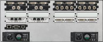
5 Inputs + Output Connections There are various types of modules which can be fitted to your CORIOmaster which must always include a CPU module and a Power Supply. For ease of identification the input/output cards are colour coded:- ¹Universal DVI allows the connection of a number of different adaptors for HDMI, VGA, Y/C, Composite, etc. ²Although other modules have two connections; the HD-SDI card allows the connection of four HD-SDI connections. ³ The DIGITAL LINK module allows for transmission of uncompressed, HDMI quality, video, audio and LAN up to 100m, with good quality cabling. The card has two independent DIGITAL LINK outputs and a single LAN input, supporting DIGITAL LINK. 5

6 Each output slots need to be assigned same layout thanks to the limitation of the processor. For example, if you have 2 layouts, you can connect 2 outputs of one boards to one layouted displays. However, if you connect to 2 different layout from one output board, you cannot assign. 6

7 User Interface ET-MWP100G uses a common PC interface for control which features a number of menu areas together with asset lists and controls. The high level menus Settings, Layouts, Canvases, Live and Comm Data are used to configure and use the system:- Settings General This menu shows the software level and the number of inputs/outputs. Ethernet Used to configure the system for IP control of a ET-MWP100G. Inputs Physical inputs into the mainframe. Most cards have two inputs per card except HD-SDI which has 4 inputs. This menu is used to configure and rename Inputs. Outputs These are the physical outputs from the mainframe. All cards have two outputs per card. This menu is used to configure and rename Inputs. Save We can save all of the System settings. This is important once changes have been made to ensure they are saved on the mainframe. Layouts Layouts An arrangement of one or more output projectors or monitor screens that will have a Canvas displayed on it. Outputs Used to select the physical outputs to be included on Canvases. A physical output can only be used on a single Canvas. Canvases Canvases This menu is used to arrange a number of video windows applied to a Layout. Layouts A canvas can be applied to one or more Layouts this is where we select which Layouts are used. Inputs The list of available system inputs is listed here. An input can be used multiple times. Presets Once we have set up a Canvas or a number of Canvases we can save them to Presets which can be recalled in this menu or in the Live mode. Live Comm Data Log Out In the Live menu we can recall Presets and change the video inputs being displayed. Comm data shows a dynamic text view of the system operations. Plus text commands can also be entered. As well as logging out of the software it is possible to save a copy of the system settings. 7
8 Getting Started Control Software ET-MWP100G is controlled using a Multi Window Processor software application in PC. Software Microsoft Windows XP + Windows 7, Windows 8 (32 or 64 Bit) Other applications Microsoft.NET.4, Microsoft Silverlight Connecting to ET-MWP100G The initial connection between the ET-MWP100G and the control PC should be via RS232 using the connector on the rear of the unit (using an USB to RS232 adaptor if your PC does not have RS232). Once connected, power up the unit at first the ET-MWP100G will set its fans at full speed. As the unit progresses through the power up sequence you will see that the lights on the input/output modules will turn green before the final unit checks after which the LED indicator on the front panel will change from red to green. With the unit is initialised and ready to use, start the control software and login. If required the Ethernet port on the ET-MWP100G can now be configure to allow the unit to be controlled over a network. 8


9 Logging in In the Settings area you can choose to control the system via RS232 or using IP. The maximum Log size can also be set. Default TCP/IP setting: IP address : Port : Please make sure to turn-off wireless signal, otherwise the system may get log-in failure. Both of these settings can be edited whilst logged in by using the General menu. The View Log button displays the Communications Log which shows all of the actions being carried out by the system. You can also Save Log to a text file if you wish to keep a copy of the log. The default Login details for your system is: Username: admin Password: adminpw Change IP Address: In order to change IP address for ET-MWP100G, need to connect via serial cable. After log-in via serial cable, you can change IP address in "Settings" >"Ethernet" after click "Take" button. 9

 is used for full screen which requires detail data, letters and drawing on large format displays and HQ is normally selected for")


10 Configuring Inputs and Outputs Before you can start to create Canvases and Layouts you must first set up your Inputs and Outputs using the Settings Menu. In the Settings menu you can access General system data, set up Ethernet network connections and we set up the Inputs and Outputs. Please configure how many displays planning to use for the system since the system requires reboot to change window configuration. Window Configuration EHQ(Extra High Quality) is used for full screen which requires detail data, letters and drawing on large format displays and HQ is normally selected for video contents. All use Panasonic s high quality interpolation and resizing algorithms so it is not possible to compare directly but the sizes of the Windows are based on following configuration: Window Configuration -EHQ Extra High Quality - HQ High Quality - PW Preview scaled resolution preferable source - up to 1920 x 1200 Suitable for detail data, letters and - up to 1024 x 1200 Video contents, Presentation - up to 224 x 128 Preview Monitor, signal check There are correlation between EHQ and HQ; 1 EHQ =2HQ. There is system limitation for max. number of windows. Besides system limitation, there is window limitation for one canvas too. ie) use 8EHQ and 8HQ in 8 EHQ mode A)If using just one canvas Max. windows are 8EHQ, 0HQ. B)If using several canvases You can use more windows in the system Canvas#1 8EHQ Canvas#2 0EHQ, 8HQ 10

11 Saving Data 1) Save to ET-MWP100G To save all system settings including presets, input and output layout, please go to "Settings" >"General" and select "Save All Settings" in Setting tab. And then, you can save whole data in non volatile memory of ET-MWP100G. To resume data, please select "Use unit data" when you log in the system. 2) Save to Local folder in connected PC To save all system settings including presets, input and output layout, please select "Log out", and you can name whole setting data and save in local folder in PC. To resume data, please select "Use local data" when you log in the system. 3) Save to SD Card for backup [Service Purpose] The other function is Backup to SD Card. An SD card is mounted on the CPU Module. If firmware update is needed, you can backup current setting into SD Card. After firmware has been updated, you can resume whole backup data from SD Card by typing control command. For the command, please check command list. 11

12 Appendix. Saved data is stored in the following folder, this is just an example, so that you cannot copy and paste following address. Address may vary dependent on OS version and setting structure. If you copy these data to deferent PC, you can use same data with different PC. [Windows7] 32bit Japanese OS C:\Users\"Username"\AppData\LocalLow\Microsoft\Silverlight\is\sku5do21.vvf \ew3v0fpq.aka\1\s\cn0h5yuupoeupbc13vuem1kaxfgf41gidh3tdd3ujvojpayk4baaaeca\f [Windows XP] Japanese OS C:\Documents and Settings\"username"\Local Settings\ApplicationData\Microsoft\Silverlight\is \ixo4f34m. u1d\tuwx4ud4.5ut\1\s \cn0h5yuupoeupbc13vuem1kaxfgf41gidh3tdd3ujvojpayk4baaaeca\f Once you saved in local PC, there are7 different files created as one saved system. ie) _demosample_CORIOmasterInputs.xml System Serial#* System Name 7 different filename Files in one system Canvases.xml Inputs.xml Layouts.xml Outputs.xml Preset.xml System.xml Windows.xml The system refers to the system serial#, so that if you swap the product, need to change system serial# as well in order to resume the data into new product. If your system configuration is different, you may not log in the ET-MWP100G. Here is the step. 1) Check system serial# of new unit You can check system serial# in "Settings" >"General" tab. 2) Change system serial# from old to new. ie) old new _demosample_CORIOmasterInputs.xml _demosample_CORIOmasterInputs.xml 3) Open "...system.xml" file. Change system serial# and overwrite the file. 4) Then, you can resume the system when you log-in a new unit. *System serial# is different from Product serial#, so that you cannot see the number unless you log-in ET-MWP100G. 12
 by default it is possible to enter a user definable name which must contain no spaces or hyphens using underscores where spaces are required.")


13 Inputs The Inputs menu is used to set up the various sources connected to ET-MWP100G. Although your inputs will be shown as Slot and Input (eg Slot1.In1) by default it is possible to enter a user definable name which must contain no spaces or hyphens using underscores where spaces are required. The card type and input status (OK, Missing) is automatically detected. However if it does not detect automatically, please select "Input Type" is to select a source type from the inputs supported by the type of connection. For example, here a DVI-U connector could be used to give us a variety of digital and analogue input types. The Colour Scale is normally set to Auto but can also be used to manually select the colour space to be used:- Black Gives a monochrome output YUV - Used for standard component sources RGB For standard computer sources eg DVI-I or VGA RGB_601/RGB_709 a variation of the RGB colour space YUV_601/YUV_709 a variation of the YUV colour space The Source Resolution and Selected Resolution are read from the Input menu. The Source Loss Colour means show the color image if no source comes through each input. Each source can have a Procamp applied to it to change Brightness and Contrast with a limited range. 13


14 Outputs The Outputs menu is used to set up the various displays that are connected to the ET-MWP100G. Although your Outputs will be shown as Slot and Input (eg Slot9.Out2) by default it is possible to enter a user definable name which must contain no spaces or hyphens using underscores where spaces are required. The output resolutions must be changed to suitable resolution since defualt resolution is settled as 1280x720p60. The output Colour Scale is normally set to Auto but can also be used to manually select the colour space to be used:- Black Gives a monochrome output YUV - Used for standard component sources RGB For standard computer sources eg DVI-I or VGA RGB_601/RGB_709 a variation of the RGB colour space YUV_601/YUV_709 a variation of the YUV colour space Genlock is used to lock the CORIOmaster to a selected output The Display Type can be selected from Monitor, Projector and None. If Projector is selected, additional projector blending options will be made available in the Layouts menu. The output colour space has to be set manually from the following options:- RGBHV VGA RGBS mixed syncs RGsB sync on green YUV DVI/HDMI 14 If the outputs display a padlock symbol it indicates that HDCP is present.
 from being copied for illegal distribution.")
15 What are HDCP & EDID? HDCP Basics HDCP stands for High-Bandwidth Digital Content Protection and was developed by Intel Corporation. HDCP is a security feature requiring communication between the sender and receiver to prevent protected material (usually High Definition video) from being copied for illegal distribution. HDCP encrypts the digital signal with a key that requires authentication from the transmitting and receiving product. If authentication fails then the signal fails, which means no picture on your screen. HDCP Support ET-MWP100G supports the HDCP Protocol. Out of the box HDCP protection is enabled so that an HDCP encrypted input may flash, not appear or appear as snow (encrypted video). To view the source you must change the HDCP settings in the Adjust Outputs and Adjust Sources menus. To be able to pass HDCP protected content through the box ensure that you select HDCP in both the Adjust Sources and Adjust Outputs menus as the default menu setting is On to ensure HDCP compliance. EDID Extended Display Identification Data (EDID) is a data provided by a digital display to describe its capabilities to a video source e.g. graphics card. It is what enables a computer to know what kinds of monitors are connected to it. The EDID includes manufacturer name and serial number, product type, timings supported by the display, display size, luminance data and pixel mapping data. Default EDID setting for ET-MWP100G is WUXGA because of its highest resolution. 15


16 Setting Up Layouts The Layouts menu is used to create physical screen layouts which can consist of a number of physical displays. Displays can be identical or of different sizes and resolutions. By default the display will be zoomed in to around 30% which is suitable for normal type layout setups. To see the complete layout area, use the Zoom control to zoom out to around 4%. In this set up two Layouts have been created already of which one has been renamed and the other left with its default name. If we look at the layout area the Two Projector Blend layout you can see ghosting on the image which shows the sources which are laid over the Layout. If we select one of the empty Layouts a list of available output displays is shown. 16


17 By selecting one of the output displays an Add Output dialogue allows you change the Actual Size of the display to adjust the display size for bezels and under scans. You can also change the Display Type which will also change the setting in the General/Outputs menu. Hitting OK will place a representation of the Output display on your Layout which will be centred over a 0/0 cross hair which indicates the centre of the Layout area. The side bar shows settings relating to the Output display that is currently selected. Zoom All changes the Zoom value to include all Output displays in your layout. Centre Layout Origin Centres the layout to 0/0. Name allows you to change the Output name. Width/Height in Layout this is where you can edit the size you set when you originally selected the Output to be shown on the Layout. Playout Centre we can move the displays using these controls to place the displays together to represent the way they are physically mounted. Normally, we use the Image Positioning Mode to change the position of Output displays. Rotation a control to change the rotation of the Output display in one degree increments/decrements. Resolution Allows you to edit the Output setting as selected in the General/Outputs menu. Display Type - Allows you to edit the Output setting as selected in the General/Outputs menu. Underneath the Take button you can select an alignment grid using Grid Setup. Grid Setup gives you fill control over the Grid including Step Size for spacing, Rotation and Offsets. 17


18 Setting up output designs Single Screen In the layouts menu select a free Layout. Multiple Output displays can be added within the 8000 x 8000 units of measure. Output displays can have Rotation applied. All Output displays can be independently moved, scales and rotated. In the layouts menu select a free Layout. Then, select Outputs from the ones that are free. Now, select the resolution and display type Projector :Edge Blending function is applicable Monitor :Edge Blending function is not applicable The monitor will now be displayed centrally over the centre marker. 18


19 Video Walls Base Size (Only used for different display/screen size layout in one canvas) Base Size is used to make layouts consisting of different sized monitors of the same resolution optimising the layout resolution to the system s internal operation. By default Base Size is set to zero which turns off the function. However, when we start to work with a series of differently sized displays but with the same resolution we need to set our Base Size which is a useful aid in producing the required positioning and sizing. Firstly, take one monitor as a reference measure the horizontal physical display excluding the bezel (it is also useful to note down bezel size at the same time) enter that as a base size. Now, when another output is added to a layout a new Base Size can be set to match that screens size. It is useful to note that the physical measurements do not have to be any particular type of unit mm, inches and pixels are possible which allow for even the largest displays to fit with the 8000 x 8000 unit allowance. 19


20 Creating Video Walls To create a video wall Canvas add two or more Outputs to a Layout. By default they will appear overlaid over the top of each other. Best practice is to move the screens on the Layout so that the centre marker is displayed in the centre of the screens. This will make later calculations much easier. With multiple outputs a quick and easy to resize and centre the display is using these buttons. Bezel Adjustment The best way to adjust and line up a video wall is to use a grid pattern across all of the screens. To allow for our screen bezel we must first know the size of the bezel, width of the display area and the resolution of the screen. Using these figures we can simply calculate the positions of our displays on the base. To calculate the settings to allow for the bezels divide the horizontal screen resolution by the visible display width (eg = 4.04). Now, use the answer and multiply it by the bezel width and times it by2 to allow for the bezels of both screens (eg 4.04 x 18 x 2= ) and round this number up or down to the nearest whole number. 20
21 Slanted Displays One of CORIOmaster s strengths is to be able display images on rotated, or slanted, displays. In this section we will examine how the following display was created to illustrate how we create complex slanted screen layouts. Screen Information: Monitors are Samsung 460UXN-3 Monitor size: (H) X (V) Display area: mm (H) x mm (V) Note: - All sizes are rounded up to the nearest mm. 21
22 Central Displays The vertical display in this example uses the display area from the spec sheet, our Horizontal size (H) in the layout is 1018 and our Vertical size (V) in layout is 573. Since it is centered in the layout, H and V Position in the layout are 0 and 0. Rotation is 90º. The monitor below it is simple as well. The size is the same and the rotation is 0º. H position is 0 as well. The vertical position is calculated using the actual monitor size instead of only the display area. This means that the bezels are accounted for. Since the positions are calculated based off the center of the images, this distance is half the horizontal size plus half of the vertical size. This is based on the center display that is rotated 90º and the display for which we are calculating the position. So this gives us (h/2)+(w/2) or (1049.4mm/2)+(602.6mm/2) = 524.7mm mm = 826mm. Since this is below the center line, the V position will be Rotated Displays The rotated displays are more difficult to account for because we cannot just go off the spec sheets. However, as everything is based off the center of the displays, as long as our sizes are based off the same scale (in this case the actual size of the displays based in mm) bezels will automatically be accounted for as well as different sized displays. 22


23 Projector Alignment The layout grid can also be used for setting up projectors for edge blending. This time however the gridlines should be spaced smaller than the projector resolution so that the outputs overlap on the layout. The maximum overlap is 500 pixels. Once the layout has been constructed and output types set to projector the projector alignment button should be pressed. This locks the output positions so that they can no longer be dragged by the mouse. Edge Alignment The user can easily set up projectors with a blended area between them. When two adjacent outputs are activated (red) then a set of alignment lines are inserted into the outputs. An outer border of green is displayed on both selected outputs and two red inner lines are shown at the join between the projectors. The user should now use these lines to correct the projectors alignment by mechanical positioning or lens control on each projector. The aim is to make sure the size of the projections are the same by use of the green boxes and that the red and green lines are both parallel with each other and are projecting on top of each other to produce a single yellow line. The user is able to produce a small amount of adjustment of the red lines in software by nudging the position of the outputs on the right-hand side. However this should only be used for minor corrections. Next we edit the Blend between the two images. Either Outputs can be adjusted at the same time or each adjusted independently by selecting only one of them. 23


24 Once all the projectors have been aligned the next stage is to correct for and brightness non linearity at the blends. This will adjust the brightness on ALL of the blends. By careful adjustment the user should be able to find the correct value that removes any brightness rise or fall originally seen. Linearity Correction allows us to control the overlap between the two projectors. The overlap is defined in the overlap area in the line-up graphic (not the amount of the projectors). With the control slid to the right the overlay has a strong gradient applied to both images which will result in a black edge in the centre of the image. Moving the slider to the left overlaps the fade out between the projectors so that the black line disappears. The Linearity Correction can also be applied using Gamma for Red, Blue and Green channels independently. This can be useful where your projectors have a different lamp life and they fade to black in slightly different hues. To adjust the various Gammas, a good way of seeing colour issues is to use a Test Signal Generator to output colour bars then White Red, Green and Blue colour fields making small adjustments until the best match across all colour fields is obtained. By clicking on the S-Curve button it is replaced with individual R G and B Gamma adjustments. The user should change the input source from White to Red green or Blue. For each of these if they see a projector outputting a different brightness then that output should be selected on the software (make it the only one red) and then adjust the appropriate gamma to remove any visible difference. When the Gamma correction has been completed a black source should be used to adjust the Black Level Boost. In very low light conditions it may be possible to see a lighter area on the blended edges. By adjusting the Black Level Boost the level of brightness on each output is raised to match that at the joins. The user should exit the Projector Alignment by clicking on the highlighted red button and then press Take to store all the settings for the newly constructed Layout. 24


25 Setting Up Canvases We have already seen that CORIOmaster can have four active Layouts. These are further defined by our four Canvasses which are used to arrange our Windows or inputs. To give flexibility on the internal routing of our Canvas designs any of the Layouts and Canvasses can be linked so that changes can be made across one or many Layouts. Later in this guide we will see how we can link to 20 system Presets to allow quick changes. 25

26 This will display the Add Window box for you to select the quality of Window you want to apply. You can also set resize settings in this window. EHQ is normally used for full screen windows on large displays, HQ is our normal window size and Preview is used for monitoring applications such as thumbnails in video walls. As soon as you hit OK on Add Window menu the Window will be displayed on the Canvas. It can be repositioned and resized using your mouse or the controls on the editing bar. 26

27 Zoom All will zoom the Canvas to include all of your Windows. Centre Canvas Origin centres the Canvas on your Windows design Window Management displays the name of the current Window selected plus allows you to change this default name. Input Name displays the name you allocated to the Input. Input Crop Settings Crops the Input and resizes the image to fit with the Window you have defined. Size Resizes the image without crops. Position & Rotation Uses figures derived from the centre of the Canvas to show the position and rotation of the Window. Border Used to apply Border colour and size to a Window. Flip Flips the image either Horizontally or Vertically. Local Aspect Control Locks the aspect to that of the Input used as a Window. Unlocking it will stretch the video horizontally. Snap to Output Snaps the Window selected to the Canvas. If more than one display is used it can also snap to a single display. Snap to Grid Snaps a Window to a Grid. Snap on Addition Will place new windows adjacent to the nearest window on the canvas. 27


28 To set up Grids select Grid Setup below the Take button. Grids are used to quickly and accurately line up Windows on our Canvas. The size, Rotation and Offset of the Grid are used to define the Grid. Window can be used to set Window sizes. Now, when we drag a Window and get the Add Window menu we can Snap to grid with the option to snap to a Grid rotation also. We can also position a Window to our Grid after placing the Window on the Canvas by selecting Snap to grid in the side menu. Grids can be used for accurate placement in the Layout and Canvas menus. For example in the Layout menu it can be used to set the size of the bezels of the output screens. 28


29 Setting Up Presets When you select the Presets menu you will see a blank list. To recall system Presets you select Get All Presets. Your CORIOmaster will then download all of the Presets from the mainframe to the control software. By default the Presets are numbered from Preset2 to Preset21. Preset1 is used by the CORIOmaster to allow for live switching between presets and is not displayed. If you press and hold on a Preset in the Save column it will save the settings and the button in the Restore column will turn green. Here we have saved a number of Presets the green button shows the currently selected preset. Selecting one of the other buttons in the Restore column will change the Canvas design and take it the Outputs. 29


30 Live Mode The Live menu is used to control your processor in changing environment where, in addition to changing Presets, you also want to change the sources of Windows. Your Presets are shown at the top of the Live menu and, as with the Presets menu, allow you to change between your various settings quickly. 30
 Backup settings to SD card. This will do a complete back up of all settings from the system flash memory onto the internally mounted Micro SD card designed for user storage.")
31 Comm Data The Comm Data menu shows a rolling display of system activity. It also has the facility for entering Control Commands. Some useful commands are:- Command Action 1 System.backupToSDCard() Backup settings to SD card. This will do a complete back up of all settings from the system flash memory onto the internally mounted Micro SD card designed for user storage. This is used to back up the settings where the system software needs to be reinstalled or updated. 2 System.RestoreBackup() Restore settings from SD card. This will write the settings saved to the user storage onto the system flash memory. This is typically done after reinstalling or upgrading the system hardware. It may not always be possible to use the backup file if the versions do not match depending on the software release. System.SaveAllSettings() This command saves the current system configuration as the power on default. 3 System.ClearSavedSettings() Save all settings to restore the settings when you restart the system. 4 System.RestoreAll() Restore all settings 5 System.Reset() Reset the system. The unit will come back up with the last saved settings. You will be required to log back in to the system to gain control. 6 Coriomax.Software_Update() Update the firmware 31
.")
32 Installation Tips Case 1 : Create large video wall with multiple units of ET-MWP100G In order to display Highest quality video wall like for the control room, it is neccessary to distribute EHQ windows for each displays. However ET-MWP100G can distribute up to 8 EHQ windows, so that multiple units may be required for the large video wall like 3x4 (12units). 2 units of ET-MWP100G can cover up to 16 EHQ windows, so that they can distribute dot-by-dot native resolution for 3x4 video wall. Here is tips to do in order to design for large video wall. Before start: Please change IP address for either of ET-MWP100G by referring page 9 to change default IP address. Setting procedure (ie. 3x4 Video wall) 1) Need tos separate network diagram for the left side and right side. 2) One ET-MWP100G should connect to 6 displays on the left, and another ET-MWP100G should connect to 6 displays on the right. 3) Each of ET-MWP100G should connect to PC through a router. 4) You can launch two control softwares simultaneously, one for left and the other for right. 5) For the border of left and right system, you need to distribute same input source by using spritter. 32


33 Case 2 : Crop window without streching image Crop Input function is crop the specific area and strech the image to fulfill original window size. So that, if you need to trim the data, need to make sure to adjust window aspect ratio. FAQ s How do I replace a module that has failed on ET-MWP100G? Pull the failed module from the unit and put in a replacement module. Although changing the module is possible with the system powered up, you must reboot the unit for it to be recognised. I am not getting any outputs on my screen or outputs are flashing or showing snow. This will normally indicate an issue with HDCP where the unit is protecting the high definition content from being copied. Enable HDCP on the Input and Output you are using. Is there a quick health check I can carry out on my unit? Many 'faults' are due to incorrect set-up or use so set the unit up with your equipment as described in this training guide. This will hopefully determine whether or not the unit is actually faulty and prevent units from being returned unnecessarily. Check the troubleshooting tips of the manual. Don t presume it is the unit that is causing the problem. Check that the equipment being used with it is fully working and setup correctly bypass the unit if possible by connecting the video source directly to the video display. Check the AC power. Is it present and is the unit turned on? Check that all cables are properly plugged in and are not damaged and then make certain that all equipment connected to the unit is working properly. It is also worth ensuring that the latest firmware is installed in the unit although, again, user settings are lost during a firmware update. 33
CORIO master C3-540 Series CORIO 3 Technology
 C3-540 CORIO master offers a new, more efficient approach to building video systems. Using TV One s Remotely latest CORIO controlled 3 technology, version it gives the user access to new levels of video
OPERATING GUIDE. HIGHlite 660 series. High Brightness Digital Video Projector 16:9 widescreen display. Rev A June A
 OPERATING GUIDE HIGHlite 660 series High Brightness Digital Video Projector 16:9 widescreen display 111-9714A Digital Projection HIGHlite 660 series CONTENTS Operating Guide CONTENTS About this Guide...
CORIO master C3-540 Series
 Key Features Manage up to 4 independent video walls Uses CORIOgrapher; simple, powerful software interface Universal DVI Inputs/Outputs: (HDMI/CV/YC/RGB/YPbPr) SDI Inputs/Outputs: SD/HD-SDI/3G-SDI to 1080p60
VSP 198CVS Quick Start
 VIEWSIZE THE WORLD VSP 198CVS Quick Start Max 2048 1152@60Hz/2560 1152 50Hz input/output resolution User customize output resolution 3G/HD/SD-SDI input Multiple cascade mapping for super resolution DVI
KRAMER ELECTRONICS LTD. USER MANUAL
 KRAMER ELECTRONICS LTD. USER MANUAL MODEL: Projection Curved Screen Blend Guide How to blend projection images on a curved screen using the Warp Generator version K-1.4 Introduction The guide describes
CORIO master C3-540 Series CORIO 3 Technology C3-540 CORIO master offers a new, more efficient approach to building video systems.
 C3-540 CORIO master offers a new, more efficient approach to building video systems. Using TV One s Remotely latest CORIO controlled 3 technology, version it gives the user access to new levels of video
Statement SmartLCT User s Manual Welcome to use the product from Xi an NovaStar Tech Co., Ltd. (hereinafter referred to as NovaStar ). It is our great
. It is our great") LED Display Configuration Software SmartLCT User s Manual Software Version: V3.0 Rev3.0.0 NS110100239 Statement SmartLCT User s Manual Welcome to use the product from Xi an NovaStar Tech Co., Ltd. (hereinafter
LED Display Configuration Software SmartLCT User s Manual Software Version: V3.0 Rev3.0.0 NS110100239 Statement SmartLCT User s Manual Welcome to use the product from Xi an NovaStar Tech Co., Ltd. (hereinafter
DB-VRC4H 4K HDMI Compact Video Wall Controller with 45 degree screen rotation
 DB-VRC4H 4K HDMI Compact Video Wall Controller with 45 degree screen rotation The DigiBird DB-VRC4H Video Wall Controller is the simplest and most cost-effective solution to build an eyecatching and creative
HD Leeza. Quick Setup Guide
 Page 1 of 15 Model KD-HD1080P Key Digital Video Processor Quick Setup Guide Have a question or a technical issue with your set-up? Call the Key Digital Hotline at: 866-439-8988 or 203-798-7187 E-mail the
G406 application note for projector
 G406 application note for projector Do you have trouble in using projector internal warp and edge blending function? Inconvenient in multiple signal source connection System resolution is not enough after
G-700LITELite multiple Channel warping processor
 G-700LITELite multiple Channel warping processor Version: 2.01, Date: 2017-07 G-700Lite is a warping processor with the ability to provide multiple processing modules to control from 1 to 4 projectors
C3-540 CORIOmaster C3-510 CORIOmaster mini CORIOgrapher V2.3
 C3-540 CORIOmaster C3-510 CORIOmaster mini CORIOgrapher V2.3 User Guide V2.00 Firmware version M402 and above PDF-C3-5x0 V2.00 Jan 2017 In this guide Welcome to CORIOgrapher Help 1 Setting up your CORIOmaster
LedSet User s Manual V Official website: 1 /
 LedSet User s Manual V2.6.1 1 / 42 20171123 Contents 1. Interface... 3 1.1. Option Menu... 4 1.1.1. Screen Configuration... 4 1.1.1.1. Instruction to Sender/ Receiver/ Display Connection... 4 1.1.1.2.
CONTENT Product Introduction... 2 Packing Configuration...3 Hardware Orientation... 4 Front Panel... 4 Back Panel... 6 Using Your Product... 7 Content
 VENUS X1PRO Quick Start 4K input support in DP, HDMI and DVI Input standard 2K formats Scale and switch seamlessly between 2K and 4K inputs Output to any format 2K or 4K EDID management on board HDCP 2.0
G-106Ex Single channel edge blending Processor. G-106Ex is multiple purpose video processor with warp, de-warp, video wall control, format
 G-106Ex Single channel edge blending Processor G-106Ex is multiple purpose video processor with warp, de-warp, video wall control, format conversion, scaler switcher, PIP/POP, 3D format conversion, image
G-106 GWarp Processor. G-106 is multiple purpose video processor with warp, de-warp, video wall control, format conversion,
 G-106 GWarp Processor G-106 is multiple purpose video processor with warp, de-warp, video wall control, format conversion, scaler switcher, PIP/POP, 3D format conversion, image cropping and flip/rotation.
SIERRA VIDEO SP-14 SETUP GUIDE. User s Manual
 SIERRA VIDEO SP-14 SETUP GUIDE User s Manual SP-14 Setup Guide Version S 1.0 1 Contents Introduction 3 The Basic System 4 Flexible Connectivity 5 Control via Front Panel Buttons 6 Set Scaler Functions
VSP 168HD Quick Start
 VSP 168HD Quick Start Support 10Gbps of transmission rate Support HDBaseT protocols and standards Support USB upgrade Max 2048 1152@60Hz/2560 816 60Hz input/output resolution Support custom output resolution
P-2 Installing the monitor (continued) Carry out as necessary
 Carry out as necessary") P-2 Installing the monitor (continued) Carry out as necessary Using the monitor without the bezel MDT552S satisfies the UL requirements as long as it is used with the bezel attached. When using the monitor
P-2 Installing the monitor (continued) Carry out as necessary Using the monitor without the bezel MDT552S satisfies the UL requirements as long as it is used with the bezel attached. When using the monitor
VSP 9516S Quick Start
 VIEWSIZE THE WORLD VSP 9516S Quick Start Max 2048 1152@60Hz/2560 816 60Hz input/output resolution User-defined resolution adjustment Picture in picture Audio and video sync Seamless switching between inputs
Table of Contents TABLE OF CONTENTS. Vivid Drive 23N User Manual Rev. 1
 User Manual TABLE OF CONTENTS Table of Contents 1. Before You Begin... 1 What Is Included... 1 Unpacking Instructions... 1 Claims... 1 Text Conventions... 1 Symbols... 1 Disclaimer... 1 Safety Notes...
Quick Guide Book of Sending and receiving card
 Quick Guide Book of Sending and receiving card ----take K10 card for example 1 Hardware connection diagram Here take one module (32x16 pixels), 1 piece of K10 card, HUB75 for example, please refer to the
Projector Management Application Version 7.00 Instruction Guide
 Projector Management Application Version 7.00 Instruction Guide Contents 1 INTRODUCTION... 4 1.1 OUTLINE... 4 1.2 SYSTEM... 4 2 INSTALLATION... 5 2.1 SYSTEM REQUIREMENTS... 5 2.2 PROJECTOR MANAGEMENT APPLICATION
CI-218 / CI-303 / CI430
 CI-218 / CI-303 / CI430 Network Camera User Manual English AREC Inc. All Rights Reserved 2017. l www.arec.com All information contained in this document is Proprietary Table of Contents 1. Overview 1.1
QUICK START GUIDE. QT Analog HD Camera & DVR Bundle ENGLISH
 QUICK START GUIDE QT Analog HD Camera & DVR Bundle ENGLISH Table of Contents Welcome What s Included...3 Understanding your DVR...4 Get Connected Registration...5 Connect Your Cameras...5 Connect DVR to
First Time Setup Guide
 First Time Setup Guide www.exhibio.com 1.877.EXHIBIO (394.4246) Exhibio ST-200 Components & Accessories Standing Mount TV Tuner with Input Cable (USB 2.0 only) VESA Mount Over-the-Air Antenna Power Adapter
G3 NET 2K USER MANUAL
 G3 NET 2K USER MANUAL Article No: RGB-RD-UM-G3 NET 2K E001 Revision No: V1.0 CONTENTS CONTENTS... 1 Declarations... 3 FCC/Warranty... 3 Operators Safety Summary... 4 Installation Safety Summary... 4 Chapter
OPERATING GUIDE. M-Vision Cine 3D series. High Brightness Digital Video Projector 16:9 widescreen display. Rev A August A
 OPERATING GUIDE M-Vision Cine 3D series High Brightness Digital Video Projector 16:9 widescreen display 112-022A Digital Projection M-Vision Cine 3D series CONTENTS Operating Guide CONTENTS About this
RMS 8424S Quick Start
 VIEWSIZE THE WORLD RMS 8424S Quick Start Standard 4 unit rack mount size 8 inch LCD 2 1024 3 (RGB) 600 16:9 / 4:3 adjustable SDI/HDMI embedded audio output via 3.5mm earphone socket Support SDI/DVI audio
DVI, HDMI, VGA, 3G-SDI, CVBS and USB are available, as are DisplayPort, HDBaseT FiberPort and H.264 IP Streaming
 Redefined SmartSlot Fully Modular Design Throughout Input & Output along with Comm. and Preview cards feature RGBlink SmartSlot technology. SmartSlot offers auto-identification and setup of the X2 based
KRAMER ELECTRONICS LTD. USER GUIDE MODEL: VP-790 Blending Projected Images on a Curved Screen. P/N: Rev 1
 KRAMER ELECTRONICS LTD. USER GUIDE MODEL: VP-790 Blending Projected Images on a Curved Screen P/N: 2900-300214 Rev 1 Contents 1 Introduction 1 2 Setting the Basic System 2 2.1 Optical Alignment 3 3 Setting
DRAFT RELEASE FOR BETA EVALUATION ONLY
 IPM-16 In-Picture Audio Metering User Manual DRAFT RELEASE FOR BETA EVALUATION ONLY Ver 0.2 April 2013 1 Contents Introduction...3 In Picture Audio Meter Displays...4 Installation...7 External Audio Board
HIGHlite Laser 3D Series High Brightness Digital Video Projector
 HIGHlite Laser 3D Series High Brightness Digital Video Projector 4INSTALLATION AND QUICK-START GUIDE 4CONNECTION GUIDE 4OPERATING GUIDE 4REFERENCE GUIDE 114-913C About This Document Follow the instructions
Table of content. Table of content Introduction Concepts Hardware setup...4
 Table of content Table of content... 1 Introduction... 2 1. Concepts...3 2. Hardware setup...4 2.1. ArtNet, Nodes and Switches...4 2.2. e:cue butlers...5 2.3. Computer...5 3. Installation...6 4. LED Mapper
2D/3D Multi-Projector Stacking Processor. User Manual AF5D-21
 2D/3D Multi-Projector Stacking Processor User Manual AF5D-21 Thank you for choosing AF5D-21 passive 3D processor. AF5D-21 is an advanced dual channel passive 3D processor with 10 bits high end scaler and
HIGHlite 660 3D Series High Brightness Digital Video Projector
 HIGHlite 660 3D Series High Brightness Digital Video Projector 4INSTALLATION AND QUICK-START GUIDE 4CONNECTION GUIDE 4OPERATING GUIDE 4REFERENCE GUIDE 114-242E About This Document Follow the instructions
Copyright 2018 Xi an NovaStar Tech Co., Ltd. All Rights Reserved. No part of this document may be copied, reproduced, extracted or transmitted in any
 MCTRL660 PRO Independent Controller Product Version: Document Number: V1.0.0 NS110100560 Copyright 2018 Xi an NovaStar Tech Co., Ltd. All Rights Reserved. No part of this document may be copied, reproduced,
Precautions and Disclaimers What You Can Do with Geometry Manager Pro Check Your Computer System requirements...
 Operating Instructions Geometric & Setup Management Software Windows Geometry Manager Pro Ver. 4.0 Thank you for purchasing this Panasonic product. Before using this software, please read the instructions
FS3. Quick Start Guide. Overview. FS3 Control
 FS3 Quick Start Guide Overview The new FS3 combines AJA's industry-proven frame synchronization with high-quality 4K up-conversion technology to seamlessly integrate SD and HD signals into 4K workflows.
C / C / C Scaling with Speed and Agility
 C2-2855 / / Scaling with Speed and Agility A new generation of Scalers tvone s evolutionary development of our renowned CORIO 2 scaler technology continues to provide commercial integrators with unsurpassed
QUICK START GUIDE QT ANALOG HD CAMERA & DVR BUNDLE ENGLISH
 QUICK START GUIDE QT ANALOG HD CAMERA & DVR BUNDLE ENGLISH Table of Contents Welcome What s Included...3 Understanding your DVR...4 Get Connected Registration...5 Connect Your Cameras...5 Connect DVR to
VIDEO GRABBER. DisplayPort. User Manual
 VIDEO GRABBER DisplayPort User Manual Version Date Description Author 1.0 2016.03.02 New document MM 1.1 2016.11.02 Revised to match 1.5 device firmware version MM 1.2 2019.11.28 Drawings changes MM 2
Matrox PowerStream Plus
 Matrox PowerStream Plus User Guide 20246-301-0100 2016.12.01 Contents 1 About this user guide...5 1.1 Using this guide... 5 1.2 More information... 5 2 Matrox PowerStream Plus software...6 2.1 Before you
Xi an NovaStar Tech Co., Ltd. User's Manual. LED Video Controller VX4S/VX4. Rev1.1.2 NS
 User's Manual LED Video Controller VX4S/VX4 Rev1.1.2 NS160110080 Statement You are welcome to use the products from (hereinafter referred to as Novastar). It is our great pleasure to offer this manual
VSP 516S Quick Start
 VIEWSIZE THE WORLD VSP 516S Quick Start Max 2048 1152@60Hz/2560 816 60Hz input/output resolution User customize output resolution 3G/HD/SD-SDI input Multiple cascade mapping for super resolution Seamless
HD/SD-SDI TO VGA CONVERTER. DAC-60 Quick Start Guide.
 HD/SD-SDI TO VGA CONVERTER DAC-60 Quick Start Guide www.datavideo.com Warranty Standard Warranty Datavideo equipment is guaranteed against any manufacturing defects for one year from the date of purchase.
Matrox PowerStream Plus
 Matrox PowerStream Plus User Guide 20246-301-0200 2017.07.04 Contents 1 About this user guide... 5 1.1 Using this guide... 5 1.2 More information... 5 2 Matrox PowerStream Plus software... 6 2.1 Before
V pro8 QUICK START GUIDE
 QUICK START GUIDE Welcome to your V pro8 FIRST STEPS POWERING ON CONNECTING YOUR COMPUTER Thank you for buying the Lawo V pro8, a true high-quality product developed and manufactured in Rastatt, Germany.
Broadcast A / V Division M-LYNX-702 V.3. Dual 7 LCD Display. User Manual
 Broadcast A / V Division M-LYNX-702 V.3 Dual 7 LCD Display User Manual Table of Contents Table of Contents 1. Package Includes 2. Product Description 2.1 Front Panel 2.2 Rear Panel Connections 3. On-Screen
HIGHlite 740 Series High Brightness Digital Video Projector
 HIGHlite 740 Series High Brightness Digital Video Projector 4INSTALLATION AND QUICK-START GUIDE 4CONNECTION GUIDE 4OPERATING GUIDE 4REFERENCE GUIDE 114-751I About This Document Please follow the instructions
USER MANUAL. HIGHlite Laser 3D Series INSTALLATION AND QUICK-START GUIDE CONNECTION GUIDE OPERATING GUIDE REFERENCE GUIDE
 HIGHlite Laser 3D Series High Brightness Digital Video Projector USER MANUAL INSTALLATION AND QUICK-START GUIDE CONNECTION GUIDE OPERATING GUIDE REFERENCE GUIDE 114-913B Digital Projection HIGHlite Laser
USER MANUAL USER MANUAL. VIO 4K Ref. V701 PROGRAMMER S GU.
 USER MANUAL VIO 4K Ref. V701 1 Table of Contents 1 Introduction... 6 1.1 Why use the VIO 4K?... 6 1.2 VIO 4K at a glance... 6 1.3 Key features... 6 1.4 Inputs... 7 1.5 Outputs... 7 1.6 Universal system
J6 User Manual. User Manual. Multi-Screen Splicing Processor J6. Xi an NovaStar Tech Co., Ltd. Rev1.0.1 NS
 J6 User Manual User Manual Multi-Screen Splicing Processor J6 Rev1.0.1 NS160110162 Statement Dear users, You are welcome to use the J6, a multi-screen splicing processor of Xi'an NovaStar Tech Co., Ltd.
Specifications Quantum Elite Series
 Specifications Quantum Elite Series Video input composite and S-video QEC I12VID Number/signal type... 12 S-video, composite video Connectors... 2 female 26-pin HD (included adapter allows input on 24
EdgeConnect Module Quick Start Guide ITERIS INNOVATION FOR BETTER MOBILITY
 EdgeConnect Module Quick Start Guide ITERIS INNOVATION FOR BETTER MOBILITY 493456301 Rev B April 2009 Table of Contents Installation... 1 Setup... 2 Operation... 4 Live Video... 4 Video Settings... 5 Network
The absolute opposite of ordinary. G804 Quad Channel Edge Blending processor
 The absolute opposite of ordinary G804 Quad Channel Edge Blending processor Input: up to 4096*2160 @60hz 4:4:4 full color sampling Output: 2048*1080 @60Hz New generation Warp & Edge blending engine Technical
USER MANUAL. HIGHlite Laser 3D Series INSTALLATION AND QUICK-START GUIDE CONNECTION GUIDE OPERATING GUIDE REMOTE COMMUNICATIONS GUIDE REFERENCE GUIDE
 HIGHlite Laser 3D Series High Brightness Digital Video Projector USER MANUAL INSTALLATION AND QUICK-START GUIDE CONNECTION GUIDE OPERATING GUIDE REMOTE COMMUNICATIONS GUIDE REFERENCE GUIDE 114-913A Digital
Operating Instructions
 Marshall Electronics Broadcast A/V Division Model No. VSW-2200 4-Input Seamless SDI A/V Switcher Operating Instructions Table of Contents 1. Overview... 2. Features.... Package Contents... 4. Specifications...
KRAMER ELECTRONICS LTD. USER MANUAL MODEL: VP-725NA Presentation Switcher/Scaler. P/N: Rev 4
 KRAMER ELECTRONICS LTD. USER MANUAL MODEL: VP-725NA Presentation Switcher/Scaler P/N: 2900-000739 Rev 4 Contents 1 Introduction 1 2 Getting Started 2 2.1 Achieving the Best Performance 2 3 Overview 3
FS1-X. Quick Start Guide. Overview. Frame Rate Conversion Option. Two Video Processors. Two Operating Modes
 FS1-X Quick Start Guide Overview Matching up and synchronizing disparate video and audio formats is a critical part of any broadcast, mobile or post-production environment. Within its compact 1RU chassis,
Live events staging. Media centers
 Christie Spyder X80 80 megapixel, true 4K@60Hz performance across multiple displays Auditoriums Control rooms Live events staging Post-production Broadcast studios Corporate lobbies Media centers Sports
Installation / Set-up of Autoread Camera System to DS1000/DS1200 Inserters
 Installation / Set-up of Autoread Camera System to DS1000/DS1200 Inserters Written By: Colin Langridge Issue: Draft Date: 03 rd July 2008 1 Date: 29 th July 2008 2 Date: 20 th August 2008 3 Date: 02 nd
Marshall Electronics. Pro A/V Communications VMV-402-SH. 3G/HD/SD-SDI Quad-viewer/Switcher with Audio Meter Display. User Manual.
 Marshall Electronics Pro A/V Communications VMV-402-SH 3G/HD/SD-SDI Quad-viewer/Switcher with Audio Meter Display User Manual Table of Contents 1. Introduction... 3 2. Features... 3 3. Package Contents...
Kramer Electronics, Ltd. USER MANUAL. Model: VP-725DSA. Presentation Switcher / Scaler
 Kramer Electronics, Ltd. USER MANUAL Model: VP-725DSA Presentation Switcher / Scaler Contents Contents 1 Introduction 1 2 Getting Started 1 2.1 Quick Start 1 3 Overview 3 4 Your VP-725DSA Presentation
Broadcast A/V Division M-LYNX-702 V.3. Dual 7 LCD Display. User Manual
 Broadcast A/V Division M-LYNX-702 V.3 Dual 7 LCD Display User Manual 1. Package Includes Table of Contents 1. Package Includes Table of Contents 01 02 One M-LYNX-702 Monitor One universal AC power adapter
Network Disk Recorder WJ-ND200
 Network Disk Recorder WJ-ND200 Network Disk Recorder Operating Instructions Model No. WJ-ND200 ERROR MIRROR TIMER HDD1 REC LINK /ACT OPERATE HDD2 ALARM SUSPEND ALARM BUZZER STOP Before attempting to connect
U S E R G U I D E HD1000
 U S E R G U I D E HD1000 1 W e l c o m e t o R o k u! In This Guide... Bring your HDTV to life with Roku. For the first time, you ll enjoy viewing your favorite digital photos in high-definition on your
IMPORTANT! This instruction guide explains how to install your CCTV system.
 IMPORTANT! This instruction guide explains how to install your CCTV system. Which accessories do you need before getting started? 1. Monitor or TV (recommended not less than 19" for clear viewing) 2. HDMI
AVG-SC121D-T. Features
 The AVG-SC121D-T is a full HD scaler switcher with 12 video, 6 audio & 2 MIC inputs. It scales & switches HDMI, VGA, YPbPr, C-Video & S- video to HDBaseT, HDMI & VGA simultaneously, and audio to a 2x20W
VENUS X1PRO-E Quick Start
 VENUS X1PRO-E Quick Start 4K input support in DP, HDMI and Dual Link DVI Support 8K x 1K, 4K x 2K Seamless Splicing EDID management Modular 2K input: Three slots for 2K input options 2K-2K and/or 4K-2K
User Manual. Multi-Screen Splicing Processor J6
 User Manual Multi-Screen Splicing Processor J6 Rev1.0.0 NS160100147 Statement Dear users, Welcome to use the J6, a multi-screen splicing processor. This manual is intended to help you to understand and
YCbCr (480i/576i) and RGBsync. 4 Press Component to change source to component connec tor. This connector supports YPbPr (480p/576p/720p/1080i)
 and RGBsync. 4 Press Component to change source to component connec tor. This connector supports YPbPr (480p/576p/720p/1080i)") Introduction Product Features This product is an XGA single chip 0.7 DLP TM projector. Outstanding features include: u True XGA, 1024 x 768 addressable pixels u Single chip DLP TM technology u NTSC3.58/NTSC4.43/PAL/SECAM
Introduction Product Features This product is an XGA single chip 0.7 DLP TM projector. Outstanding features include: u True XGA, 1024 x 768 addressable pixels u Single chip DLP TM technology u NTSC3.58/NTSC4.43/PAL/SECAM
EZwindow4K-LL TM Ultra HD Video Combiner
 EZwindow4K-LL Specifications EZwindow4K-LL TM Ultra HD Video Combiner Synchronizes 1 to 4 standard video inputs with a UHD video stream, to produce a UHD video output with overlays and/or windows. EZwindow4K-LL
Kramer Electronics, Ltd. USER MANUAL. Model: VP-725DS. Presentation Switcher / Scaler
 Kramer Electronics, Ltd. USER MANUAL Model: VP-725DS Presentation Switcher / Scaler Contents Contents 1 Introduction 1 2 Getting Started 1 2.1 Quick Start 1 3 Overview 3 4 Your VP-725DS Presentation Switcher
Statement Welcome to use the product from Xi an NovaStar Tech Co., Ltd. (hereinafter referred to as Novastar ). It is our great pleasure to offer this
. It is our great pleasure to offer this") User's Manual LED Display Video Controller VX2U/VX4U XI'AN NOVASTAR TEC Rev1.0.3 NS160100228 Statement Welcome to use the product from Xi an NovaStar Tech Co., Ltd. (hereinafter referred to as Novastar
User's Manual LED Display Video Controller VX2U/VX4U XI'AN NOVASTAR TEC Rev1.0.3 NS160100228 Statement Welcome to use the product from Xi an NovaStar Tech Co., Ltd. (hereinafter referred to as Novastar
HD/SD-SDI TO VGA CONVERTER. DAC-60 Quick Start Guide.
 HD/SD-SDI TO VGA CONVERTER DAC-60 Quick Start Guide www.datavideo.com Warranty Standard Warranty Datavideo equipment is guaranteed against any manufacturing defects for one year from the date of purchase.
ivw-fd122 Video Wall Controller MODEL: ivw-fd122 Video Wall Controller Supports 2 x 2 Video Wall Array User Manual Page i Rev. 1.
 MODEL: ivw-fd122 Video Wall Controller Supports 2 x 2 Video Wall Array User Manual Rev. 1.01 Page i Copyright COPYRIGHT NOTICE The information in this document is subject to change without prior notice
Model VS-2A 2-Port VGA Switch with Audio & Serial Control
 Model VS-2A 2-Port VGA Switch with Audio & Serial Control UMA1119 Rev B Copyright Hall Research, Inc. All rights reserved. 1163 Warner Ave Tustin, CA 92780, Ph: (714)641-6607, Fax -6698 Model VS-2A 2 2-Port
TABLE OF CONTENTS. 03 Overview. 04 Working Environment. 06 User Interface Introduction 08 FAQ. 41 Glossary and Abbreviations.
 2 TABLE OF CONTENTS 03 Overview Checking Info 15 Updating the Firmware 16 04 Working Environment Setting Video Format 18 Supported OS 04 Setting Volume 21 Supported Hardwares 04 Setting Input 27 Setting
Statement Dear users: Welcome to use Nova's Products. We are pleased to offer this manual to help you understand and use the product. In the preparati
 User's Manual LED Display Video Controller VX4 VX4S Rev1.0.0 NS160100018 Statement Dear users: Welcome to use Nova's Products. We are pleased to offer this manual to help you understand and use the product.
CP 3072S Quick Start
 VIEWSIZE THE WORLD CP 3072S Quick Start 4 channels, 16 signal sources Preview and program outputs separately PIP between any two inputs Seamless switching between any two channels Seamless switching between
User Instruction Manual IQSDA30/IQSDA32. Intelligent Reclocking High Performance HD-SDI/SD-SDI Distribution Amplifiers. snellgroup.
 User Instruction Manual IQSDA30/IQSDA32 Intelligent Reclocking High Performance HD-SDI/SD-SDI Distribution Amplifiers snellgroup.com IQSDA30/IQSDA32 www.snellgroup.com Information and Notices Information
Omega 4K/UHD Three-Input Switcher. Introduction. Applications. for HDMI and USB-C with HDBaseT and HDMI Outputs
 Introduction The Atlona AT-OME-ST31 is a 3 1 switcher and HDBaseT transmitter with HDMI and USB-C inputs. It features mirrored HDMI and HDBaseT outputs and is HDCP 2.2 compliant. The USB-C input is ideal
VENUS X1 USER MANUAL
 VENUS X1 USER MANUAL Article No: RGB-RD-UM-X1 E001 Revision No: V1.5 CONTENTS CONTENTS... 1 Declarations... 3 FCC/Warranty... 3 Operators Safety Summary... 4 Installation Safety Summary... 4 Chapter 1
2-Channel Video Processor Models C2-7260, C2-7210, C2-7200
 C2-7260 2-Channel 17-Input Video Processor moves well beyond video processing, switching and HD-SDI Up, Down and Cross Convers ion by providing many additional features. Two independent video processing
SCHD24K 4K UHD + HDMI to HDMI Scaler
 SCHD24K 4K UHD + HDMI to HDMI Scaler Operation Manual DISCLAIMERS The information in this manual has been carefully checked and is believed to be accurate. Ampronix assumes no responsibility for any infringements
Logic Controls LV3000 VGA Connected Virtual Pole Display
 One Blue Hill Plaza, 16 th Floor, PO Box 1546 Pearl River, NY 10965 1-800-PC-AMERICA, 1-800-722-6374 (Voice) 845-920-0800 (Fax) 845-920-0880 Logic Controls LV3000 VGA Connected Virtual Pole Display This
MultiQ Digital signage template system for widescreen monitors
 Technical Note MultiQ Digital signage template system for widescreen monitors This document is intended as a guide for users of the MultiQ Digital Signage Template System for widescreen monitors in landscape
Network Camera Operating Manual
 Network Camera Operating Manual Model No. WV-NW484S Before attempting to connect or operate this product, please read these instructions carefully and save this manual for future use. Preface About these
Modular Video Wall Controller
 Modular Video Wall Controller isemc T Series Equipped for incorporating any sort of video and information source on any showcase divider design, isemc video wall controllers are generally utilized for
The absolute opposite of ordinary
 The absolute opposite of ordinary G408 4K/60 vido wall controller 2x HDMI 2.0 in, 8x FHD out 10-bit processor 4:4:4 Chroma sampling Independent rotation/ scaling/ cropping Also serve as two Quad channel
Safety Information. Do Not
 Safety Information Do Read, keep, and follow instructions. Heed all warnings. Turn off and unplug the power plug from the AC outlet before cleaning the unit. Use a soft dry cloth with mild detergent to
Setting Up the Warp System File: Warp Theater Set-up.doc 25 MAY 04
 Setting Up the Warp System File: Warp Theater Set-up.doc 25 MAY 04 Initial Assumptions: Theater geometry has been calculated and the screens have been marked with fiducial points that represent the limits
GV-3D People Counter 3DPCV10-A
 GV-3D People Counter User's Manual Before attempting to connect or operate this product, please read these instructions carefully and save this manual for future use. 3DPCV10-A 2013 GeoVision, Inc. All
DM-TX-201-C DigitalMedia 8G+ Transmitter. Supplemental Guide Crestron Electronics, Inc.
 DM-TX-201-C DigitalMedia 8G+ Transmitter Supplemental Guide Crestron Electronics, Inc. The product warranty can be found at www.crestron.com/warranty. The specific patents that cover Crestron products
icon H600: Network centric visualization
 icon H600: Network centric visualization NEW YORK LONDON TOKYO High-definition, multi-site information sharing revolutionizes the way you work as a team Easy operation using wireless mouse and keyboard
4K Presentation switcher-scaler Chameleon PS200/300 series 2017
 4K Presentation switcher-scaler Chameleon PS200/300 series 2017 Chameleon PS200/300 series HQUltra technology was chosen by the European Broadcast Union for frame rate and standards conversion of the recent
C / C / C Scaling with Speed and Agility
 / / Scaling with Speed and Agility A new generation of Scalers tvone s evolutionary development of our renowned CORIO 2 scaler technology continues to provide commercial integrators with unsurpassed image
Globalmediapro SMR-650
 Globalmediapro SMR-650 16 x 16 Modularized Hybrid 3G-SDI Matrix Operation Manual CONTENTS 1. Introduction... 1 2. Applications... 1 3. Package Contents... 1 4. System Requirements... 1 5. Features... 2
Quick Reference. PowerLite Pro Z9750UNL/Z9870UNL Z10000UNL/Z10005UNL
 PowerLite Pro Z9750UNL/Z9870UNL Z10000UNL/Z10005UNL Quick Reference This Quick Reference card gives brief instructions on connecting your PowerLite projector and using common features. For details, see