Microcontroller Interfacing: Selected Topics
|
|
|
- Beatrix Oliver
- 5 years ago
- Views:
Transcription
.")
1 Microcontroller Interfacing: Selected Topics Operation of LCD Displays Common Input Devices Common Output Devices and Actuators 10/29/ Liquid crystal twists light polarization by 90 degrees if no E field present, and by 0 degrees if an E field is present (since presence of an AC or DC E field straightens out the liquid crystal molecules). NOTE: The upper polarizer may be aligned to pass light with leftright polarization, while the lower polarizer may be aligned to pass light with a polarization that is into/out of the paper. Thus an AC waveform > 2.8V rms applied across electrodes, the LC molecules straightened out so the light polarization is not rotated as it passes through the LC, and so the light never gets through the lower polarizer, and the segment is black, but if < 1.7V rms, the light polarization is twisted by 90 degrees, 10/29/2008 and the segment is white. 2
, but have no long range order in the other")
2 10/29/ Liquid crystals encompass a broad group of materials that posses the properties of both a solid and a liquid. More specifically, they are a liquid with molecules oriented in one common direction (having a long range and repeating pattern-- definition of a crystal), but have no long range order in the other two directions. For example, all the molecules form lines are oriented in the Y direction (up and down), but they posses no common ordering in the x direction (disorder is also assumed in the Z direction). To more easily visualize this, think a 1-molecule-thick slice (one layer of molecules to be exact) of a block of liquid crystal material. If you examined another slice, the molecules would still be oriented in the Y direction, but they would be in different positions along the X-axis. By stacking millions of these thin slices, the Z direction is built up and as a result of the change in relative position on the x-axis, the Z direction has no long range order. 10/29/2008 4
3 Liquid crystals must be aligned to the top and bottom pieces of glass in order to obtain the desired twist. In other words, the 90 degree twist is formed by anchoring the liquid crystal on one glass plate and forcing it to twist across the cell gap (the distance between the two glass plates) when contacting the second plate. Furthermore, The actual image quality of the display will be dependent on the surface alignment of the LC material. The method currently used for aligning liquid crystals was developed by the Dai-Nippon Screening (English= Big Japan Screening) Company. The process consists of coating the top and bottom sheets of glass with a Polyimide based film. The top piece of glass is coated and rubbed in a particular orientation; the bottom panel/polyimide is rubbed perpendicular (90 degrees for TN displays) with respect to the top panel. It was discovered that by rubbing the polyimide with a cloth, nanometer (1 X 10⁻⁹ meters) size grooves are formed and the liquid crystals align with the direction of the grooves. It is common that when assembling a TN LC cell, it will be necessary to eliminate patches of nonuniform areas. The two parameters required to eliminate the nonuniformities and complete the TN LC display are pretilt angle and cholesteric impurities. 10/29/ There's more to building an LCD than simply creating a sheet of liquid crystals. The combination of four facts makes LCDs possible: Light can be polarized. Liquid crystals can transmit and change the polarization of polarized light. The structure of liquid crystals can be changed by an electric field. There are transparent substances that can conduct electricity. An LCD is a device that uses these four facts in a surprising way. To create an LCD, you take two sheets of polarized glass. A special polymer that creates microscopic grooves in the surface is rubbed on the side of the glass that does not have the polarizing film on it. The grooves must be in the same direction as the polarizing film. You then add a coating of nematic liquid crystals to one of the filters. The grooves will cause the first layer of molecules to align with the filter's orientation. Then add the second piece of glass with the polarizing film at a right angle to the first piece. Each successive layer of TN molecules will gradually twist until the uppermost layer is at a 90-degree angle to the bottom, matching the polarized glass filters. As light strikes the first filter, it is polarized. The molecules in each layer then guide the light they receive to the next layer. As the light passes through the liquid crystal layers, the molecules also change the light's plane of vibration to match their own angle. When the light reaches the far side of the liquid crystal substance, it vibrates at the same angle as the final layer of molecules. If the final layer is matched up with the second polarized glass filter, then the light will pass through. 10/29/2008 6


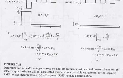
4 , Twisted Nematic Liquid Crystal Image courtesy Dr. Oleg Lavrentovich, Liquid Crystal Institute 10/29/ We have seen that a typical LCD display segment requires <1.7V rms front-toback electrode to turn OFF the segment, and >2.8V rms to turn ON the segment. HOWEVER, the dc component or average value of the front-to-back electrode voltage waveform MUST BE 0, or the LCD display will suffer permanent damage. 10/29/2008 8


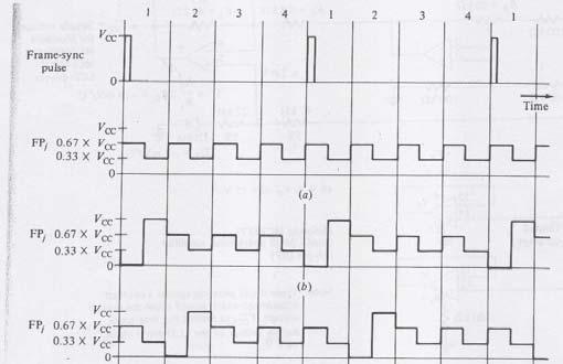
5 Note how the FP1 electrodes are passed under by one BP1, one BP2, one BP3, and one BP4 electrode. The same goes for the FP2, FP3,, FP8 electrodes. 10/29/ Note that the BP signals are always the same, and are shown below for 1:4 LCD display multiplexing. 10/29/


6 10/29/ /29/


7 CUSTOM LCD Display Example using 1:4 Multiplexing: NOTE: Top two edge finger connections on left and right side are the four backplane connections. The rest of the edge fingers are frontplane connections which connect to exactly four segments. 10/29/ /29/


8 10/29/ /29/

9 10/29/ /29/

10 INPUT DEVICES FOR EMBEDDED DESIGN 10/29/ Switches 10/29/


11 A. DIP SWITCH 10/29/ B. Microswitch Internal structure of SPDT Microswitch 10/29/
12 A micro switch is a generic term used to refer to a small electric switch that is able to be actuated by very little physical force. They are very common due to their low cost and extreme durability, typically greater than 1 million cycles and up to 10 million cycles for heavy duty models. This durability is a natural consequence of the design. Internally a stiff metal strip must be bent to activate the switch. This produces a very distinctive clicking sound and a very crisp feel. When pressure is removed the metal strip springs back to its original state. Common applications of micro switches include computer mouse buttons and arcade game's joysticks and buttons. Micro switches are commonly used in tamper switches on gate valves on fire sprinkler systems and other water pipe systems, where it is necessary to know if a valve has been opened or shut. The defining feature of micro switches is that a relatively small movement at the actuator button produces a relative large movement at the electrical contacts, which occurs at high speed (regardless of the speed of actuation). Most successful designs also exhibit mechanical hysteresis meaning that a small reversal of the actuator is insufficient to reverse the contacts; there must be a significant movement in the opposite direction. Both of these characteristics help to achieve a clean and reliable interruption to the switched circuit. 10/29/ C. SPST Switch Debouncing (Needed when driving a counter, etc.) Vc1 Schmitt Input Hysteresis: Vt- = 1.5 V, Vt+ = 2.5 V => AC noise on Vc1 may be as large as = 1 v without causing output changes. Vt+ Vt- Vc1 close open t 10/29/

13 D. BCD Encoded Thumbwheel Switch 10/29/ E. Magnetic Reed Switch The reed switch contains two magnetizable and electrically conductive ferromagnetic reeds which have end portions separated by a small gap when the switch is open. The reeds are hermetically sealed in opposite ends of a tubular glass envelope to guard against contact corrosion. A magnetic field (from an electromagnet or a permanent magnet) will cause the contacts to pull together, thus completing an electrical circuit. The stiffness of the reeds causes them to separate, and open the circuit, when the magnetic field ceases It was invented at Bell Telephone Laboratories in 1936 by W. B. Elwood 10/29/

14 10/29/ One important quality of the switch is its sensitivity, the amount of magnetic energy necessary to actuate it. Sensitivity is measured in units of Ampere-turns, corresponding to the current in a coil multiplied by the number of turns. Typical pull-in sensitivities for commercial devices are in the 10 to 60 AT range. Thus a small coil of wire may be wound around the reed switch to turn it into a reasonably sensitive reed relay. Reed switches are commonly used in mechanical systems as proximity switches, in door and window sensors in burglar alarm systems and in safety interlocks. Reed switches were formerly used in the keyboards for computer terminals, where each key had a magnet and a reed switch actuated by depressing the key. Speed sensors on bicycles use a reed switch to detect when the magnet on the wheel passes the sensor. 10/29/

 through the following output sequence: 01111111 10111111 11011111 11101111 11110111 11111011 11111101 11111110 After each number is output,")
15 A reed switch combined with an electromagnet becomes a reed relay. The electromagnet consists of a coil with the reed switch inside. Reed relays are used when high operating speed is required, or where very low-level signals must be switched. 10/29/ F. Software scanned keypad (Scanning accomplished without using bidirectional ports) 64 key keypad scanned using one 8-bit output port and one 8-bit input port. Output port scans keypad by repetitively cycling (scanning) through the following output sequence: After each number is output, the input port is read, and if 0xFFis read the scan continues. If some other value than 0xFF is read (just one 0),scanning stops, and the position of the 0 at the output port and the position of the 0 read at the input port locate the key that was pressed! 10/29/


16 G. Optoelectronic Switches 10/29/ Reflective Optoelectronic Switch 10/29/


17 UPC Bar Code Scanning Wand Coding table for left half of the UPC bar code.. The coding table for the right half has The black and white areas exchanged. Using a reflective optoelectronic switch as the scanning wand, black => high level (1) and white => low level (0). Note the 101 SYNC patterns at both ends of the code and the middle 0101 pattern 10/29/ Transmissive Optoelectronic Switch Light Emitting Diode (LED) and Phototransistor (PT) face each other from opposite sides of the sensor. When an object interrupts the light beam, the output rises from 0V to 5 V. 10/29/

18 Optical Tachometer If codewheel has 360 equally spaced light/dark changes around its periphery, then the number of output pulses counted in 1 second yields the speed of angular rotation in degrees/second. 10/29/ Sensing Direction of Rotation as well as angular displacement Count rising edges of A to determine the angular displacement. Check level on B when A rises in order to deduce direction of rotation (either Clockwise (B=1) or CounterClockwise (B=0) 10/29/

19 Displacement sensing for mouse, trackball, or dc motor in robotics 10/29/ Optoisolator Consider a transmissive optoelectronic switch with its air gap sealed. What good is this? Actually, it is still quite useful! It may be used in signal transmission and electrical shock isolation systems! For example, in the digital communication link shown on the next slide, the grounds at the two sites are at different potentials which differ by V1 volts. (During an electrical storm, the difference in ground potentials at two different sites might be as high as 2500 V!). If these grounds were connected directly together, excessive current would flow through the ground wire, and the wire will melt. Use of the optoisolator no longer requires the grounds to be tied together between the two remote locations. 10/29/


20 Using an optoisolator To provide Ground Fault Isolation in a Digital Communication Link 10/29/ H. Magnetic Sensing without moving parts Hall Effect Switch Unlike a permanent magnet moving past a inductive pickup coil, which, by Faraday s Law of Induction, is more sensitive to faster moving magnets, the Hall Effect Switch is position, not velocity, dependent. Even the presence of a stationary magnet can be detected with the Hall Effect Device. 10/29/
21 1.6 x C 10/29/ /29/
 so that the N-type material used in the Hall effect device forms a")

22 Note that the P-type substrate is connected to the lowest voltage in the circuit (ground) so that the N-type material used in the Hall effect device forms a reverse biased isolation junction that isolates the Hall effect device from the rest of the circuitry on the IC. 10/29/ Integrated Hall Effect Sensor 10/29/

23 10/29/ /29/


24 2. Digital Shaft Angle Encoder (Binary vs. Gray Coded) 10/29/ Optical Gray-Coded Encoder Disk 10/29/

25 3. Interfacing Analog Sensors via A/D Converter 10/29/ The A/D Converter makes it possible to connect many different kinds of Analog Sensors (Transducers) to a microcontroller. Such transducers convert any different physical quantities that occur naturally in analog form into analog voltage, which then converted by the A/D into binary numbers. For example: transducers are available for measuring: Displacement (position) Velocity Acceleration Temperature Pressure Light Intensity, Light Color (Wavelength) Humidity Etc., Etc, Etc. 10/29/
26 Analog Sensor Characteristics Sensors have certain characteristics which should be specified in the data sheet: Sensitivity Offset Range Linearity Error Accuracy Resolution Stability Reference level Transfer function and Interdependence. 10/29/ Analog Sensor Specifications: 10/29/

27 10/29/ Output Devices/Actuators 10/29/


28 LED Displays 10/29/ Multiplexed 8-Digit 7-Segment LED Display 10/29/


29 Driving high power loads (Solenoids, stepper motors, lamps, etc.) 10/29/ SCR can only conduct during the positive half of a sine wave! Triac can conduct during both positive and negative half of a sine wave 10/29/
30 10/29/ /29/

31 10/29/ /29/


32 10/29/ Triacs: Switching BOTH halves of the 60 Hz AC Cycle 10/29/


33 Solid-state Relay -Allows microcontroller to switch on/off a high current, 115 VAC load device. -Magnetically Isolated to protect microcontroller side from lightning strikes on the 115 VAC power line side. -Could also employ optical isolation via optoisolator. 10/29/ /29/
34 H-bridge --- Bidirectional DC Motor Control Note: TIP107 s s are PNP and act as current sources. TIP102 s s are NPN and act as current sinks. 10/29/ FWD REV ENA* Description Turn on upper left source and lower right sink. (go forward) Disable lower right sink. When ENA* is fed a PWM signal the bridge modulates the "forward" current through the motor Turn on both lower left sink and lower right sink, shorting the motor. This causes a rotating motor to stop rotating so this mode is called "Braking." Disable both lower sinks. When ENA* is fed a PWM signal the bridge modulates the "braking" of the motor Turn on the upper right source and lower left sink. (go backward) Disable lower left sink. When ENA* is fed a PWM signal the bridge modulates the "reverse" current through the motor Turn off all sources and sinks. Motor coasts. Braking is NOT engaged Turn off all sources and sinks. Motor coasts. Braking is NOT engaged. 10/29/


35 Permanent Magnet Stepper Motor => Magnetic field steps 90 degrees / revolution from B 00 to B 01 to B 11 to B 10 10/29/ Assume that the rotor is made up of 3 permanent bar magnets equi-angularly spaced at 120 degrees with respect to each other. Imagine that one of the South (S) poles of the rotor is initially aligned with the initial magnetic field B 00 When the microcontroller steps the magnetic field by 90 degrees (from B 00 to B 01 ), the nearest south pole is attracted into alignment with B 01, and the rotor rotates counter clockwise by = 30 degrees. Due to symmetry, it is easy to see that this process repeats with each 90 degree step of the magnetic field B, and the motor executes 30 degree steps, or 12 steps per revolution as the B field is stepped from B 00 -> B 01 -> B 11 -> B 10 etc. B 00 3-Pole Permament Magnet Rotor => 30 degree stepsize, or 12 steps per revolution B 01 10/29/ = 30 degrees
36 Switching Inductive Loads: Diode Transient Protection 10/29/ /29/

37 10/29/ /29/
38 10/29/ /29/

39 10/29/ /29/

40 Inkjet Printer 10/29/ /29/

41 10/29/ Positioning the ink dots Accurate placement of ink dots on the page is critical to achieving uniform colors without banding. Optical encoders precisely control the location of the printed dots, both across and down the page. An optical encoder consists of three main components: a light emitting diode, a photodetector, and a transparent code wheel or code strip positioned between the light emitter and the detector. The motion of the ink jet carriage across the page is controlled by a long plastic code strip which extends across the full width of the print zone. This code strip passes between a light emitter and detector mounted on the moving carriage. 10/29/
42 To the casual observer, this plastic strip might look like an unimportant light gray piece of flimsy plastic sheet material, but it is actually one of the keys to the precision of the whole ink jet mechanism. It consists of a dense array of precision black stripes printed on a thin sheet of clear plastic, which make it look from a distance like it is a uniform color of light gray. As the carriage passes each stripe, the light beam is interrupted and the photodetector generates a synchronization pulse which controls the timing of the ink drop ejection. These synchronization signals insure that the ink drops are printed in accurate locations even if there is some variation in the carriage velocity, or if the carriage is accelerating or decelerating near the beginning or end of its travel. 10/29/ Color LCD Display 10/29/
43 Passive LCD Display Panels use a simple grid to supply the charge to a particular pixel on the display. Creating the grid is quite a process! It starts with two glass layers called substrates. One substrate is given columns and the other is given rows made from a transparent conductive material. This is usually indium-tin oxide. The rows or columns are connected to integrated circuits that control when a charge is sent down a particular column or row. The liquid crystal material is sandwiched between the two glass substrates, and a polarizing film is added to the outer side of each substrate. 10/29/ Active-matrix LCDs depend on thin film transistors (TFTs). Basically, TFTs are tiny switching transistors and capacitors. They are arranged in a matrix on a glass substrate. To address a particular pixel, the proper row is switched on, and then a charge is sent down the correct column. Since all of the other rows that the column intersects are turned off, only the capacitor at the designated pixel receives a charge. 10/29/
44 The capacitor is able to hold the charge until the next refresh cycle. And if we carefully control the amount of voltage supplied to a crystal, we can make it untwist only enough to allow some light through. By doing this in very exact, very small increments, LCDs can create a gray scale. Most displays today offer 256 levels of brightness per pixel. 10/29/ An LCD that can show colors must have three subpixels with red, green and blue color filters to create each color pixel. Through the careful control and variation of the voltage applied, the intensity of each subpixel can range over 256 shades. Combining the subpixels produces a possible palette of 16.8 million colors (256 shades of red x 256 shades of green x 256 shades of blue). These color displays take an enormous number of transistors. 10/29/

45 For example, a typical laptop computer supports resolutions up to 1,024x768. If we multiply 1,024 columns by 768 rows by 3 subpixels, we get 2,359,296 transistors etched onto the glass! If there is a problem with any of these transistors, it creates a "bad pixel" on the display. Most active matrix displays have a few bad pixels scattered across the screen. 10/29/ Color TFT LCD Panel 10/29/


46 Driving TFT LCD Display Pixel 10/29/ Structure of Color TFT Panel 10/29/


47 Vertical Structure of Pixel 10/29/ Active Addressing of 3 x 3 Matrix 10/29/


48 Examples of how RGB subpixels create a colored pixel 10/29/ /29/
UNIT V 8051 Microcontroller based Systems Design
 UNIT V 8051 Microcontroller based Systems Design INTERFACING TO ALPHANUMERIC DISPLAYS Many microprocessor-controlled instruments and machines need to display letters of the alphabet and numbers. Light
Chapter 9 MSI Logic Circuits
 Chapter 9 MSI Logic Circuits Chapter 9 Objectives Selected areas covered in this chapter: Analyzing/using decoders & encoders in circuits. Advantages and disadvantages of LEDs and LCDs. Observation/analysis
These are used for producing a narrow and sharply focus beam of electrons.
 CATHOD RAY TUBE (CRT) A CRT is an electronic tube designed to display electrical data. The basic CRT consists of four major components. 1. Electron Gun 2. Focussing & Accelerating Anodes 3. Horizontal
Liquid Crystal Displays
 Liquid Crystal Displays Cosmin Ioniţă - Spring 2006 - A brief history 1888 - Friedrich Reinitzer, an Austrian chemist working in the Institute of Plant Physiology at the University of Prague, discovered
Display Devices & its Interfacing
 Display Devices & its Interfacing 3 Display systems are available in various technologies such as i) Cathode ray tubes (CRTs), ii) Liquid crystal displays (LCDs), iii) Plasma displays, and iv) Light emitting
28 North Lotts, Dublin 1, Ireland Tel: info [AT] phonevolts.com
![28 North Lotts, Dublin 1, Ireland Tel: info [AT] phonevolts.com](/thumbs/91/104995975.jpg "28 North Lotts, Dublin 1, Ireland Tel: info [AT] phonevolts.com") www.phonevolts.ie 28 North Lotts, Dublin 1, Ireland Tel: 01 8728722 Email: info [AT] phonevolts.com PhoneVolts is owned and operated by GSMsolutions.ie What is an LCD? A liquid crystal display (commonly
www.phonevolts.ie 28 North Lotts, Dublin 1, Ireland Tel: 01 8728722 Email: info [AT] phonevolts.com PhoneVolts is owned and operated by GSMsolutions.ie What is an LCD? A liquid crystal display (commonly
Screens; media that use additive primaries
 Image display Display is the final stage in the image processing pipeline: Continuous scenes are acquired and digitally processed. The display process essentially converts the discrete image back to continuous
High-resolution screens have become a mainstay on modern smartphones. Initial. Displays 3.1 LCD
 3 Displays Figure 3.1. The University of Texas at Austin s Stallion Tiled Display, made up of 75 Dell 3007WPF LCDs with a total resolution of 307 megapixels (38400 8000 pixels) High-resolution screens
the Most Popular Display Technology?
 Why is LCD the Most Popular Display Technology? History of Liquid Crystal Display (LCD) As early as 1889, scientists discovered that chemicals such as cholesteryl benzoate, when melted into liquid form,
Computer Graphics : Unit - I
 Computer Graphics Unit 1 Introduction: Computer Graphics it is a set of tools to create, manipulate and interact with pictures. Data is visualized through geometric shapes, colors and textures. Video Display
Liquid Crystal Display (LCD)
") Liquid Crystal Display (LCD) When coming into contact with grooved surface in a fixed direction, liquid crystal molecules line up parallelly along the grooves. When coming into contact with grooved surface
Liquid Crystal Display (LCD) When coming into contact with grooved surface in a fixed direction, liquid crystal molecules line up parallelly along the grooves. When coming into contact with grooved surface
Digital Systems Based on Principles and Applications of Electrical Engineering/Rizzoni (McGraw Hill
 Digital Systems Based on Principles and Applications of Electrical Engineering/Rizzoni (McGraw Hill Objectives: Analyze the operation of sequential logic circuits. Understand the operation of digital counters.
Monitor and Display Adapters UNIT 4
 Monitor and Display Adapters UNIT 4 TOPIC TO BE COVERED: 4.1: video Basics(CRT Parameters) 4.2: VGA monitors 4.3: Digital Display Technology- Thin Film Displays, Liquid Crystal Displays, Plasma Displays
Types of CRT Display Devices. DVST-Direct View Storage Tube
 Examples of Computer Graphics Devices: CRT, EGA(Enhanced Graphic Adapter)/CGA/VGA/SVGA monitors, plotters, data matrix, laser printers, Films, flat panel devices, Video Digitizers, scanners, LCD Panels,
Technology White Paper Plasma Displays. NEC Technologies Visual Systems Division
 Technology White Paper Plasma Displays NEC Technologies Visual Systems Division May 1998 1 What is a Color Plasma Display Panel? The term Plasma refers to a flat panel display technology that utilizes
Durham Magneto Optics Ltd. NanoMOKE 3 Wafer Mapper. Specifications
 Durham Magneto Optics Ltd NanoMOKE 3 Wafer Mapper Specifications Overview The NanoMOKE 3 Wafer Mapper is an ultrahigh sensitivity Kerr effect magnetometer specially configured for measuring magnetic hysteresis
4.9 BEAM BLANKING AND PULSING OPTIONS
 4.9 BEAM BLANKING AND PULSING OPTIONS Beam Blanker BNC DESCRIPTION OF BLANKER CONTROLS Beam Blanker assembly Electron Gun Controls Blanker BNC: An input BNC on one of the 1⅓ CF flanges on the Flange Multiplexer
Chapter 3. Display Devices and Interfacing
 Chapter 3 Display Devices and Interfacing Monitor Details Collection of dots Matrix of dots creates character Monochrome monitor screen is collection of 350 *720 350 rows and each rows having 720 dots
Transducers and Sensors
 Transducers and Sensors Dr. Ibrahim Al-Naimi Chapter THREE Transducers and Sensors 1 Digital transducers are defined as transducers with a digital output. Transducers available at large are primary analogue
CATHODE RAY OSCILLOSCOPE. Basic block diagrams Principle of operation Measurement of voltage, current and frequency
 CATHODE RAY OSCILLOSCOPE Basic block diagrams Principle of operation Measurement of voltage, current and frequency 103 INTRODUCTION: The cathode-ray oscilloscope (CRO) is a multipurpose display instrument
Display Systems. Viewing Images Rochester Institute of Technology
 Display Systems Viewing Images 1999 Rochester Institute of Technology In This Section... We will explore how display systems work. Cathode Ray Tube Television Computer Monitor Flat Panel Display Liquid
VARIOUS DISPLAY TECHNOLOGIESS
 VARIOUS DISPLAY TECHNOLOGIESS Mr. Virat C. Gandhi 1 1 Computer Department, C. U. Shah Technical Institute of Diploma Studies Abstract A lot has been invented from the past till now in regards with the
Innovative Rotary Encoders Deliver Durability and Precision without Tradeoffs. By: Jeff Smoot, CUI Inc
 Innovative Rotary Encoders Deliver Durability and Precision without Tradeoffs By: Jeff Smoot, CUI Inc Rotary encoders provide critical information about the position of motor shafts and thus also their
2.2. VIDEO DISPLAY DEVICES
 Introduction to Computer Graphics (CS602) Lecture 02 Graphics Systems 2.1. Introduction of Graphics Systems With the massive development in the field of computer graphics a broad range of graphics hardware
Development of Simple-Matrix LCD Module for Motion Picture
 Development of Simple-Matrix LCD Module for Motion Picture Kunihiko Yamamoto* Shinya Takahashi* Kouki Taniguchi* * A1203 Project Team Abstract A simple-matrix LCD module (12.1-in. SVGA) has been developed
EM1. Transmissive Optical Encoder Module Page 1 of 9. Description. Features
 Description Page 1 of 9 The EM1 is a transmissive optical encoder module designed to be an improved replacement for the HEDS-9000 series encoder module. This module is designed to detect rotary or linear
SPECIFICATION NO Model 207 Automatic GTAW Welding System
 1.0 Introduction The Model 207 is a completely self-contained Gas Tungsten Arc Welding (GTAW) System requiring only input power, inert gas and AMI Welding Head (or manual torch) for operation. Its small
Basically we are fooling our brains into seeing still images at a fast enough rate so that we think its a moving image.
 Basically we are fooling our brains into seeing still images at a fast enough rate so that we think its a moving image. The formal definition of a Moving Picture... A sequence of consecutive photographic
Display Technologies CMSC 435. Slides based on Dr. Luebke s slides
 Display Technologies CMSC 435 Slides based on Dr. Luebke s slides Recap: Transforms Basic 2D Transforms: Scaling, Shearing, Rotation, Reflection, Composition of 2D Transforms Basic 3D Transforms: Rotation,
1. Introduction. 1.1 Graphics Areas. Modeling: building specification of shape and appearance properties that can be stored in computer
 1. Introduction 1.1 Graphics Areas Modeling: building specification of shape and appearance properties that can be stored in computer Rendering: creation of shaded images from 3D computer models 2 Animation:
Lecture Flat Panel Display Devices
 Lecture 13 6.111 Flat Panel Display Devices Outline Overview Flat Panel Display Devices How do Displays Work? Emissive Displays Light Valve Displays Display Drivers Addressing Schemes Display Timing Generator
Elements of a Television System
 1 Elements of a Television System 1 Elements of a Television System The fundamental aim of a television system is to extend the sense of sight beyond its natural limits, along with the sound associated
Displays and framebuffers
 Reading Optional Displays and framebuffers Brian Curless CSE 557 Autumn 2017 OpenGL Programming Guide (the red book available online): First four sections of chapter 2 First section of chapter 6 Foley
AF-300 E11 Adjustable Frequency Drive
 AF-300 E11 Adjustable Frequency Drive The AF-300 E11 adjustable frequency drive is GE s new generation of micro drives. GE recognized your need for a high-performance, full-featured compact drive and designed
DISPLAY TECHNOLOGIES. Group 6: Steve Lenhart, Ryan King, Ramsey Akl, and Andrew Scheib
 DISPLAY TECHNOLOGIES Group 6: Steve Lenhart, Ryan King, Ramsey Akl, and Andrew Scheib DISPLAY TECHNOLOGIES Group 6: Steve Lenhart, Ryan King, Ramsey Akl, and Andrew Scheib Introduction First computers
Hello and welcome to this training module for the STM32L4 Liquid Crystal Display (LCD) controller. This controller can be used in a wide range of
 controller. This controller can be used in a wide range of") Hello and welcome to this training module for the STM32L4 Liquid Crystal Display (LCD) controller. This controller can be used in a wide range of applications such as home appliances, medical, automotive,
Hello and welcome to this training module for the STM32L4 Liquid Crystal Display (LCD) controller. This controller can be used in a wide range of applications such as home appliances, medical, automotive,
Lt DELTA USA, Inc
 Infrared LOOP SCANNER Rota-Sonde TS2006 Infrared - high sensitivity 480 F or 750 F Quick and easy commissioning Self-monitoring and alarm functions Lt 1037 1 Applications R o t a - S o n d e TS2 0 0 6
Considerations for Specifying, Installing and Interfacing Rotary Incremental Optical Encoders
 Considerations for Specifying, Installing and Interfacing Rotary Incremental Optical Encoders Scott Hewitt, President SICK STEGMANN, INC. Dayton, OH www.stegmann.com sales@stegmann.com 800-811-9110 The
ED3. Digital Encoder Display Page 1 of 13. Description. Mechanical Drawing. Features
 Description Page 1 of 13 The ED3 is an LCD readout that serves as a position indicator or tachometer. The ED3 can display: Speed or position of a quadrature output incremental encoder Absolute position
SPECIFICATION NO NOTE
 NOTE The Model 207-1 is a special version of the standard M-207 Power Supply. It has been altered for a special applications requiring low current operation at high arc voltages in ambient and pressurized
CHAPTER 9. Actives Devices: Diodes, Transistors,Tubes
 CHAPTER 9 Actives Devices: Diodes, Transistors,Tubes 1 The electrodes of a semiconductor diode are known as anode and cathode. In a semiconductor diode, electrons flow from cathode to anode. In order for
EM1. Transmissive Optical Encoder Module Page 1 of 8. Description. Features
 Description Page 1 of 8 The EM1 is a transmissive optical encoder module designed to be an improved replacement for the HEDS-9000 series encoder module. This module is designed to detect rotary or linear
Digital High Resolution Display Technology. A New Way of Seeing Things.
 R Digital High Resolution Display Technology A New Way of Seeing Things. Raytheon s Digital Display Digital Light Processing (DLP ) by Texas Instruments is a revolutionary new way to project and display
MTI-2100 FOTONIC SENSOR. High resolution, non-contact. measurement of vibration. and displacement
 A worldwide leader in precision measurement solutions MTI-2100 FOTONIC SENSOR High resolution, non-contact measurement of vibration and displacement MTI-2100 Fotonic TM Sensor Unmatched Resolution and
CATHODE-RAY OSCILLOSCOPE (CRO)
") CATHODE-RAY OSCILLOSCOPE (CRO) I N T R O D U C T I O N : The cathode-ray oscilloscope (CRO) is a multipurpose display instrument used for the observation, measurement, and analysis of waveforms by plotting
CATHODE-RAY OSCILLOSCOPE (CRO) I N T R O D U C T I O N : The cathode-ray oscilloscope (CRO) is a multipurpose display instrument used for the observation, measurement, and analysis of waveforms by plotting
Flat Panel Displays: LCD Technologies and Trends
 Flat Panel Displays: LCD Technologies and Trends Robert Dunhouse, Sr. Engineering Manager, Display BU Class ID: 4C01B Renesas Electronics America Inc. Robert F. Dunhouse, Jr. Sr. Engineering Manager, Display
ID C10C: Flat Panel Display Basics
 ID C10C: Flat Panel Display Basics Renesas Electronics America Inc. Robert Dunhouse, Display BU Engineering Manager 12 October 2010 Revision 1.1 Robert F. Dunhouse, Jr. Displays Applications Engineering
6-DIGIT FREQUENCY METER, TACHOMETER, RATE METER, TIMER, PULSE TOTALIZER, PROCESS METER & TOTALIZER WITH RS-232 PENTA P6000
 6-DIGIT FREQUENCY METER, TACHOMETER, RATE METER, TIMER, PULSE TOTALIZER, PROCESS METER & TOTALIZER WITH RS-232 PENTA P6000 NEWPORT PRODUCT INFO MANUAL (HTML) - (PDF Version) P6000A/P5000 - INPUT OPTIONS
MODULE I MCA COMPUTER GRAPHICS ADMN APPLICATIONS OF COMPUTER GRAPHICS
 MODULE 1 1. APPLICATIONS OF COMPUTER GRAPHICS Computer graphics is used in a lot of areas such as science, engineering, medicine, business, industry, government, art, entertainment, advertising, education
Computer Graphics Prof. Sukhendu Das Dept. of Computer Science and Engineering Indian Institute of Technology, Madras Lecture - 5 CRT Display Devices
 Computer Graphics Prof. Sukhendu Das Dept. of Computer Science and Engineering Indian Institute of Technology, Madras Lecture - 5 CRT Display Devices Hello everybody, welcome back to the lecture on Computer
EM1. Transmissive Optical Encoder Module Page 1 of 8. Description. Features
 Description Page 1 of 8 The EM1 is a transmissive optical encoder module. This module is designed to detect rotary or linear position when used together with a codewheel or linear strip. The EM1 consists
PTIK UNNES. Lecture 02. Conceptual Model for Computer Graphics and Graphics Hardware Issues
 E3024031 KOMPUTER GRAFIK E3024032 PRAKTIK KOMPUTER GRAFIK PTIK UNNES Lecture 02 Conceptual Model for Computer Graphics and Graphics Hardware Issues 2014 Learning Objectives After carefully listening this
Sep 09, APPLICATION NOTE 1193 Electronic Displays Comparison
 Sep 09, 2002 APPLICATION NOTE 1193 Electronic s Comparison Abstract: This note compares advantages and disadvantages of Cathode Ray Tubes, Electro-Luminescent, Flip- Dot, Incandescent Light Bulbs, Liquid
Modular Lube Lubrication Systems System Controls
 Model 84501 Program Timer Solid State Designed to control the lubrication cycle frequency of air-operated single-stroke pumps. Timer turns pump on/off at programmed intervals via a 3-way or 4-way air solenoid
1.5mm amplitude at 10 to 55Hz frequency in each X, Y, Z direction for 2 hours 500m/s² (approx. 50G) in each X, Y, Z direction for 3 times
 in each X, Y, Z direction for 3 times") Color Mark Color Mark Feature Outstanding color matching accuracy - RGB light emitting diodes and 12-bit resolution - 2 detection modes (color only / color + intensity) - -step sensitivity adjustment for
Color Mark Color Mark Feature Outstanding color matching accuracy - RGB light emitting diodes and 12-bit resolution - 2 detection modes (color only / color + intensity) - -step sensitivity adjustment for
Overview of All Pixel Circuits for Active Matrix Organic Light Emitting Diode (AMOLED)
") Chapter 2 Overview of All Pixel Circuits for Active Matrix Organic Light Emitting Diode (AMOLED) ---------------------------------------------------------------------------------------------------------------
Chapter 2 Overview of All Pixel Circuits for Active Matrix Organic Light Emitting Diode (AMOLED) ---------------------------------------------------------------------------------------------------------------
Data Sheet. Electronic displays
 Data Pack F Issued November 0 029629 Data Sheet Electronic displays Three types of display are available; each has differences as far as the display appearance, operation and electrical characteristics
Part No. ENC-LAB01 Users Manual Introduction EncoderLAB
 PCA Incremental Encoder Laboratory For Testing and Simulating Incremental Encoder signals Part No. ENC-LAB01 Users Manual The Encoder Laboratory combines into the one housing and updates two separate encoder
Physics in Entertainment and the Arts
 Physics in Entertainment and the Arts Chapter XXII Audio/Video Recording and Playback Audio Recording and Playback This diagram shows the basic processes for recording and playing back sound Sound Sensor
Exercise 4-2. Counting of Actuator Cycles EXERCISE OBJECTIVE & & &
 Exercise 4-2 EXERCISE OBJECTIVE To describe the operation of an electrical counter; To assemble and test a continuous reciprocation system; To extend and retract a cylinder a definite number of times using
Electrical & Electronic Measurements: Class Notes (15EE36) Module-5. Display Devices
 Module-5. Display Devices") Module-5 Display Devices Syllabus: Introduction Character formats Segment displays Dot matrix displays Bar graph displays Cathode ray tubes Light emitting diodes Liquid crystal displays Nixies Incandescent
Module-5 Display Devices Syllabus: Introduction Character formats Segment displays Dot matrix displays Bar graph displays Cathode ray tubes Light emitting diodes Liquid crystal displays Nixies Incandescent
This module senses temperature and humidity. Output: Temperature and humidity display on serial monitor.
 Elegoo 37 Sensor Kit v2.0 Elegoo provides tutorials for each of the sensors in the kit provided by Maryland MESA. Each tutorial focuses on a single sensor and includes basic information about the sensor,
Bill of Materials: Super Simple Water Level Control PART NO
 Super Simple Water Level Control PART NO. 2169109 Design a simple water controller in which electrodes are required to sense high and low water levels in a tank. Whenever the water level falls below the
Cylindrical Photoelectric Sensor CY-100 SERIES
 Cylindrical Photoelectric Sensor CY-00 SERIES Listing (2 m cable length type only) Features Wide product range Shape: Standard type Side view type Connector: 2 m cable length type M2 plug-in connector
Operating Instructions (ed. 5.97) Electronic Preset Counter Type Series 904
 Electronic Preset Counter Type Series 904") Operating Instructions 3.96.3 (ed. 5.97) Electronic Preset Counter Type Series 904 1. Description 6 digit preset counter, 2 presets, add./subtr. bright 2-line LCD display with symbols for activated outputs
Operating Instructions 3.96.3 (ed. 5.97) Electronic Preset Counter Type Series 904 1. Description 6 digit preset counter, 2 presets, add./subtr. bright 2-line LCD display with symbols for activated outputs
Vorne Industries. 87/719 Analog Input Module User's Manual Industrial Drive Itasca, IL (630) Telefax (630)
 Telefax (630)") Vorne Industries 87/719 Analog Input Module User's Manual 1445 Industrial Drive Itasca, IL 60143-1849 (630) 875-3600 Telefax (630) 875-3609 . 3 Chapter 1 Introduction... 1.1 Accessing Wiring Connections
Vorne Industries 87/719 Analog Input Module User's Manual 1445 Industrial Drive Itasca, IL 60143-1849 (630) 875-3600 Telefax (630) 875-3609 . 3 Chapter 1 Introduction... 1.1 Accessing Wiring Connections
Gechstudentszone.wordpress.com
 Unit 3: Photodiodes 3.1 Photodiodes Photodiodes are junction semiconductor light sensors that generate current or voltage when the PN junction in the semiconductor is illuminated by light of sufficient
Hitachi Europe Ltd. ISSUE : app084/1.0 APPLICATION NOTE DATE : 28/04/99
 APPLICATION NOTE DATE : 28/04/99 Design Considerations when using a Hitachi Medium Resolution Dot Matrix Graphics LCD Introduction Hitachi produces a wide range of monochrome medium resolution dot matrix
Single Axis Position Controller
 SERIES P9511 Single Axis Position Controller Compact Construction Simple Go-to operation Integrated Relay Output Integrated Mains Power Supply ELEKTRO-TRADING sp. Z o.o. 44-109 Gliwice, ul. Mechaników
Operating instructions Electronic preset counter Type series 717
 Operating instructions Electronic preset counter Type series 717 1. Description 5.98.3_gb 6-digit adding/subtracting counter with two presets Very bright 8mm high LED display Counting and preset range
Semiconductors Displays Semiconductor Manufacturing and Inspection Equipment Scientific Instruments
 Semiconductors Displays Semiconductor Manufacturing and Inspection Equipment Scientific Instruments Electronics 110-nm CMOS ASIC HDL4P Series with High-speed I/O Interfaces Hitachi has released the high-performance
SCALE & WEIGHT DISPLAYS
 The MICRO SERIES SCALE & WEIGHT DISPLAYS LARGE DIGIT MODELS Mighty-5S DPM MODELS Micro-S & Mighty-1S Mighty-1S Micro-S ELECTRO-NUMERICS, INC. Introduction The Electro-Numerics family of Digital Panel Meters
Understanding VFD. Variable Frequency Drive. nfi. nfi
 Understanding VFD Variable Frequency Drive Practical Demonstration of VFD Delta- M Series 1.5 KW I/P: 230V 1/3 Phase O/P: 230 3 Phase VFD Status Screen Motor OFF Command Freq. Parameters Direction Amperes
FP-QUAD-510. Features. Power Requirement OPERATING INSTRUCTIONS. 4-Axis, Quadrature Input Module
 OPERATING INSTRUCTIONS FP-QUAD-510 4-Axis, Quadrature Input Module These operating instructions describe the installation, features, and characteristics of the FP-QUAD-510. For details on configuring and
General Specifications
 General Specifications WG41F11C Compact O Frame GS 14M04B10-20E-Z1 [Style: S1] Overview The WG41F11C Compact O frame is a space-saving frame designed for coating lines of battery electrode sheets. This
UNIVERSAL DIGITAL METER DC Volts and Amps AC RMS Volts and Amps Thermocouples and RTDs Process Signals Strain Gauge and Load Cell
 99 Washington Street Melrose, MA 02176 Fax 781-665-0780 TestEquipmentDepot.com UNIVERSAL DIGITAL METER DC Volts and Amps AC RMS Volts and Amps Thermocouples and RTDs Process Signals Strain Gauge and Load
Spatial Light Modulators XY Series
 Spatial Light Modulators XY Series Phase and Amplitude 512x512 and 256x256 A spatial light modulator (SLM) is an electrically programmable device that modulates light according to a fixed spatial (pixel)
THE CAPABILITY to display a large number of gray
 292 JOURNAL OF DISPLAY TECHNOLOGY, VOL. 2, NO. 3, SEPTEMBER 2006 Integer Wavelets for Displaying Gray Shades in RMS Responding Displays T. N. Ruckmongathan, U. Manasa, R. Nethravathi, and A. R. Shashidhara
Ch. 1: Audio/Image/Video Fundamentals Multimedia Systems. School of Electrical Engineering and Computer Science Oregon State University
 Ch. 1: Audio/Image/Video Fundamentals Multimedia Systems Prof. Ben Lee School of Electrical Engineering and Computer Science Oregon State University Outline Computer Representation of Audio Quantization
THE ASTRO LINE SERIES GEMINI 5200 INSTRUCTION MANUAL
 THE ASTRO LINE SERIES GEMINI 5200 INSTRUCTION MANUAL INTRODUCTION The Gemini 5200 is another unit in a multi-purpose series of industrial control products that are field-programmable to solve multiple
Application Note [AN-007] LCD Backlighting Technologies and Configurations
![Application Note [AN-007] LCD Backlighting Technologies and Configurations](/thumbs/81/83266365.jpg "Application Note [AN-007] LCD Backlighting Technologies and Configurations") Application Note [AN-007] LCD Backlighting Technologies Introduction Liquid Crystal Displays (LCDs) are not emissive i.e. they do not generate their own light. Transmissive and transflective displays require
Application Note [AN-007] LCD Backlighting Technologies Introduction Liquid Crystal Displays (LCDs) are not emissive i.e. they do not generate their own light. Transmissive and transflective displays require
.152 (3.86) KEYWAY DEPTH .033 (.84).066 (1.68) .550 DIA (13.97) MOUNTING SURFACE .350 (8.89) 3/8-32 UNEF-2A THREADS (19.71.
 KEYWAY DEPTH .033 (.84).066 (1.68) .550 DIA (13.97) MOUNTING SURFACE .350 (8.89) 3/8-32 UNEF-2A THREADS (19.71.") Optical SERIES 61K High Resolution, 4-Pin FEATURES 25, 32, 50, 64, 100, 128 and 256 Cycles per Revolution Available Sealed Version Available Rugged Construction Cable or Pin Versions 10 Million Rotational
Optical SERIES 61K High Resolution, 4-Pin FEATURES 25, 32, 50, 64, 100, 128 and 256 Cycles per Revolution Available Sealed Version Available Rugged Construction Cable or Pin Versions 10 Million Rotational
SPECIAL SPECIFICATION 1987 Single Mode Fiber Optic Video Transmission Equipment
 1993 Specifications CSJ 0027-12-086, etc. SPECIAL SPECIFICATION 1987 Single Mode Fiber Optic Video Transmission Equipment 1. Description. This Item shall govern for the furnishing and installation of color
(Cat. No IJ, -IK)
") (Cat. No. 1771-IJ, -IK) Product Data The Encoder/Counter Module Assembly (cat. no. 1771-IJ or 1771-IK) maintains a count, independent of the processor, of input pulses that may typically originate from
(Cat. No. 1771-IJ, -IK) Product Data The Encoder/Counter Module Assembly (cat. no. 1771-IJ or 1771-IK) maintains a count, independent of the processor, of input pulses that may typically originate from
Digital Light Processing
 A Seminar report On Digital Light Processing Submitted in partial fulfillment of the requirement for the award of degree of Bachelor of Technology in Computer Science SUBMITTED TO: www.studymafia.org SUBMITTED
PSC300 Operation Manual
 PSC300 Operation Manual Version 9.10 General information Prior to any attempt to operate this Columbia PSC 300, operator should read and understand the complete operation of the cubing system. It is very
(12) United States Patent (10) Patent No.: US 6,885,157 B1
 United States Patent (10) Patent No.: US 6,885,157 B1") USOO688.5157B1 (12) United States Patent (10) Patent No.: Cok et al. (45) Date of Patent: Apr. 26, 2005 (54) INTEGRATED TOUCH SCREEN AND OLED 6,504,530 B1 1/2003 Wilson et al.... 345/173 FLAT-PANEL DISPLAY
USOO688.5157B1 (12) United States Patent (10) Patent No.: Cok et al. (45) Date of Patent: Apr. 26, 2005 (54) INTEGRATED TOUCH SCREEN AND OLED 6,504,530 B1 1/2003 Wilson et al.... 345/173 FLAT-PANEL DISPLAY
PROFESSIONAL D-ILA PROJECTOR DLA-G11
 PROFESSIONAL D-ILA PROJECTOR DLA-G11 A new digital projector that projects true S-XGA images with breakthrough D-ILA technology Large-size projection images with all the sharpness and clarity of a small-screen
Experiment 9A: Magnetism/The Oscilloscope
 Experiment 9A: Magnetism/The Oscilloscope (This lab s "write up" is integrated into the answer sheet. You don't need to attach a separate one.) Part I: Magnetism and Coils A. Obtain a neodymium magnet
PROFESSIONAL D-ILA PROJECTOR DLA-G11
 PROFESSIONAL D-ILA PROJECTOR DLA-G11 A new digital projector that projects true S-XGA images with breakthrough D-ILA technology Large-size projection images with all the sharpness and clarity of a small-screen
1995 Metric CSJ SPECIAL SPECIFICATION ITEM 6031 SINGLE MODE FIBER OPTIC VIDEO TRANSMISSION EQUIPMENT
 1995 Metric CSJ 0508-01-258 SPECIAL SPECIFICATION ITEM 6031 SINGLE MODE FIBER OPTIC VIDEO TRANSMISSION EQUIPMENT 1.0 Description This Item shall govern for the furnishing and installation of color Single
General Items: Reading Materials: Miscellaneous: Lecture 8 / Chapter 6 COSC1300/ITSC 1401/BCIS /19/2004. Tests? Questions? Anything?
 General Items: Tests? Questions? Anything? Reading Materials: Miscellaneous: F.Farahmand 1 / 14 File: lec7chap6f04.doc What is output? - A computer processes the data and generates output! - Also known
Polarization Engineering for LCD Projection
 Polarization Engineering for LCD Projection Michael G. Robinson, Jianmin Chen, and Gary D. Sharp Colorlink Inc., USA John Wiley & Sons, Ltd Contents Series Editor's Foreword Preface XIII XV 1 Introduction
16 Stage Bi-Directional LED Sequencer
 16 Stage Bi-Directional LED Sequencer The bi-directional sequencer uses a 4 bit binary up/down counter (CD4516) and two "1 of 8 line decoders" (74HC138 or 74HCT138) to generate the popular "Night Rider"
ORDERING Page 6 BASLER RELAY STANDARDS, DIMENSIONS, ACCESSORIES Request bulletin SDA
 BE1-59NC CAPACITOR NEUTRAL OVERVOLTAGE RELAY The BE1-59NC Capacitor Neutral Overvoltage Relay provides sensitive protection for capacitor banks. ADDITIONAL INFORMATION INSTRUCTION MANUAL ADVANTAGES Helps
Dynamic Animation Cube Group 1 Joseph Clark Michael Alberts Isaiah Walker Arnold Li
 Dynamic Animation Cube Group 1 Joseph Clark Michael Alberts Isaiah Walker Arnold Li Sponsored by: Department of Electrical Engineering & Computer Science at UCF What is the DAC? The DAC is an array of
Type SCH94FO. Type SCH94FO. Description
 Type SCH94FO Hollow Shaft Fiber Optic Encoder - Ø 94 mm Dual Output Option (Digital & Fiber Optic) Fiber Optic Transmission up to 2,000 meters (~ 1.25 miles) No Degradation of Encoder Signal from Electrical
Lecture 17 Microwave Tubes: Part I
 Basic Building Blocks of Microwave Engineering Prof. Amitabha Bhattacharya Department of Electronics and Communication Engineering Indian Institute of Technology, Kharagpur Lecture 17 Microwave Tubes:
A comprehensive guide to control room visualization solutions!
 A comprehensive guide to control room visualization solutions! Video walls Multi output and 4K display Thin Client Video Extenders Video Controller & Matrix switcher Table of Contents Introduction... 2
EPROM pattern generator with "Genlock"
 EPROM pattern generator with "Genlock" This generator uses an EPROM to store several pictures that can then be selected by means of a thumb-wheel switch. Alternatively, if the pictures stored are in a