THE NEW AXIAL BUNCHER AT INFN-LNS
|
|
|
- Doris Allen
- 5 years ago
- Views:
Transcription


1 17/09/2013 Antonio Caruso / Cyc13 Vancouver 1 THE NEW AXIAL BUNCHER AT INFN-LNS Antonio Caruso INFN-LNS
2 17/09/2013 Antonio Caruso / Cyc13 Vancouver 2 Talking points Main reasons for a new axial buncher Buncher study Design: mechanical, electrical, numerical simulations LLRF system of the buncher Test and measurements Conclusions References Discussion
3 17/09/2013 Antonio Caruso / Cyc13 Vancouver 3 New axial buncher, main reasons. Present axial buncher is installed along the vertical beam line inside the yoke of the cyclotron at about half meter from the median plane. INFN-LNS K-800 SUPERCONDUCTING CYCLOTRON Maintenance and technical inspection are very difficult to carry out in this situation.

4 17/09/2013 Antonio Caruso / Cyc13 Vancouver 4 New axial buncher, main reasons. Present Buncher Position INTERNAL 3m Maintenance and technical inspection should be much easier Median plane 0,5 m Axial beam line New Axial Buncher Position INFN-LNS K-800 SUPERCONDUCTING CYCLOTRON EXTERNAL Present axial buncher is installed along the vertical beam line inside the yoke of the cyclotron at about half meter from the median plane. Maintenance and technical inspection are very difficult to carry out in this situation.


5 17/09/2013 Antonio Caruso / Cyc13 Vancouver 5 0,5 m cyclotron 1,4 m Just to give an idea of the complexity involved in maintenance work of the present buncher beam line Present buncher V A C U U M Covering flange A I R Axial beam line 3 1/8 coax line, water cooling pipe inside the inner coax, dated Same position today removing the present buncher in case of failures, maintenance can be problematic


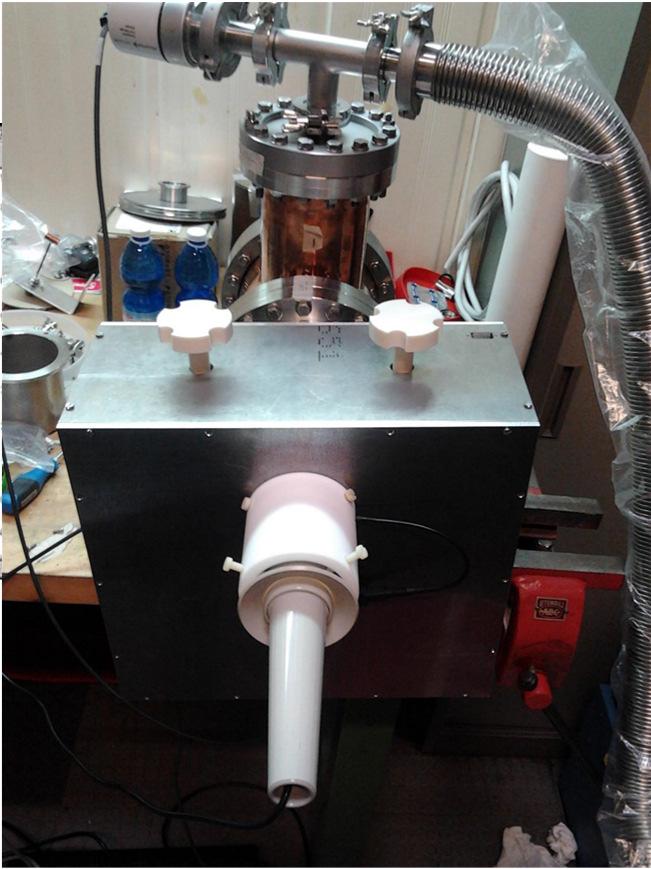
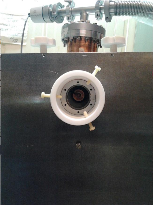
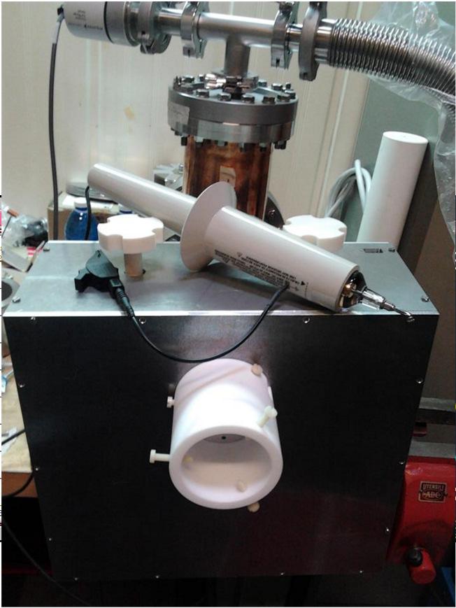
6 17/09/2013 Antonio Caruso / Cyc13 Vancouver 6 0,5 m 3,8 m 3 m Present buncher NEW AXIAL BUNCHER POSITION 3 1/8 RIGID COAX LINE V A C U U M Covering flange A I R Axial Beam line Axial beam line 3 1/8 coax line, water cooling pipe inside the inner coax, in Same position today
7 17/09/2013 Antonio Caruso / Cyc13 Vancouver 7 THE AXIAL BUNCHER STUDY the buncher consists of a drift tube driven by a sinusoidal RF signal in the range of MHz, a matching box, an amplifier, and an electronic control system.


8 17/09/2013 Antonio Caruso / Cyc13 Vancouver 8 Basic two gap buncher structure 0 Z L g1 L d1 L g2 L d2 Drift tube BEAM LINE ION SOURCE V b CYCLOTRON L g1 and L g2 It is a drift tube, fed by a sinusoidal voltage and placed between two grounded tube electrodes. are the two gaps of 5 mm length The distance between the Buncher and the inflector at the cyclotron central region (time focus) is 3011 mm, and it is imposed by mechanical constraints
9 17/09/2013 Antonio Caruso / Cyc13 Vancouver 9 Ion source beam table "Ion" "MeV/n" "Vo(kV)" Fh2(MHz)" "Vb(Volt)" 1 "4 He 1+" 2 "4 He 2+" 3 "4 He 2+" 4 "9 Be 3+" 5 "12 C 3+" "13 C 4+" We now 7 "27Al 9+" illustrate the 8 "40Ar9+" typical case for 9 "48Ca9+" α particles 10"48Ca15+" particle velocity z=0 charge Voltage source output electrode / mass (with f cyclotron frequency) is the path of the particles in one period and, because of the fixed geometry of the cyclotron central region, has to be constant L d1 = 83.5 mm drift tube length This length is chosen so that L d1 +L g1 is an odd integer multiple of the (N+1/2) / in our case with N=2 and βλ=35,4 mm 11"58Ni 21+" 12"84Kr 17+" Sn 31+" Sn 21+" Xe 31+" Au 31+" Au 36" βλ = constant
10 17/09/2013 Antonio Caruso / Cyc13 Vancouver 10 α Charged particle case "Ion" "MeV/n" "Vo(kV)" Fh2(MHz)" 1 "4 He 1+" "4 He 2+" L g1 = L g2 = 5 mm L d1 = 83.5 mm L d2 = 3011 mm - L g2 (L d1 /2) = mm 3 "4 He 2+" particle velocity when it arrives at the z = 0 position, due to the ion source voltage Ion specie considered = 4 He 2+ Ion source voltage - V s = kv sin /0.95 V rad/s mm Cyclotron acceptance interval phase = 35 o

11 17/09/2013 Antonio Caruso / Cyc13 Vancouver 11 In this case the calculated particle trajectories are shown in the Applegate diagrams, referred to one period 3011 mm Cyclotron entrance Cyclotron entrance Applegate diagram. There is the indication of the z-position of the Cyclotron entrance. Cyclotron entrance Enlarged view of the Applegate diagram. There is the indication of the z-position of the Cyclotron entrance.

12 17/09/2013 Antonio Caruso / Cyc13 Vancouver 12 In the graph the plot of t d2 versus t 0 /T is shown. The voltage has been applied to optimize the particle transmission within the cyclotron acceptance time, referred to the 35 o phase. This is clearly shown, where the curve is tangent to the dotted boundaries. Cyclotron acceptance time interval Arrival time of each particle at the Cyclotron entrance, with respect to the t 0 time when each particle arrives at the z = 0 position. T = 1/f. Cyclotron acceptance time interval Enlarged view of Figure on the left. T = 1/f. Under these conditions the particle transmission to the cyclotron is TR = 57.6%, and the energy spread is / 1.15%.
13 17/09/2013 Antonio Caruso / Cyc13 Vancouver 13 Mechanical design (drift tube mostly) Median plane Ground 3m Drift tube New axial buncher Axial beam line New Axial Buncher Position EXTERNAL


 Median")


14 17/09/2013 Antonio Caruso / Cyc13 Vancouver 14 Mechanical design (drift tube mostly) Median plane Ground 3m Drift tube New axial buncher Axial beam line New Axial Buncher Position EXTERNAL

15 17/09/2013 Antonio Caruso / Cyc13 Vancouver 15 Mechanical details mm Standard flange DN100 CF Standard flange DN160 CF 403 mm 83.5 mm New axial buncher 75 mm Standard feed-through Ground electrodes Drift tube
16 17/09/2013 Antonio Caruso / Cyc13 Vancouver 16 Copper deposition STEEL Drift tube copper made. COPPER Galvanic copper deposition on the ground electrodes and beam line All surfaces are in copper (except flanges). Consequently Q-factor increases, prevents/minimizes any copper surfaces facing a steel surface under high vacuum COPPER
 and to connect the ground electrodes to the beam line (a, c).")
17 17/09/2013 Antonio Caruso / Cyc13 Vancouver 17 Soldering technique A soft soldering has been adopted to connect the feed-through to the drift tube, copper-copper (b). T.I.G welding technique T.I.G. welding has been adopted to weld the flange at ground (steelsteel) and to connect the ground electrodes to the beam line (a, c). COPPER Soft soldering copper-copper


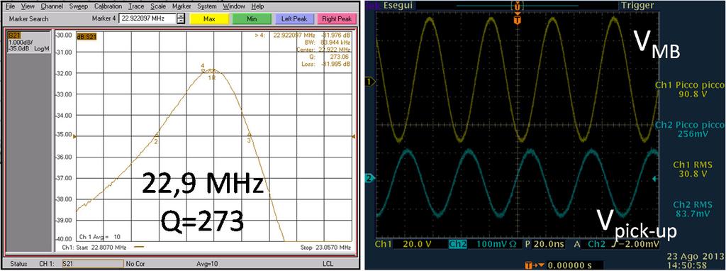
18 17/09/2013 Antonio Caruso / Cyc13 Vancouver 18 Electrical design DRIFT TUBE From the electrical point of view the drift tube can be seen as a capacitance. C MHz An LCR meter confirms the simulated capacitance value of about 27pF and, with a vector network analyser, the selfresonance of 352,75 MHz has been measured through an N-adaptor.
 and")
19 17/09/2013 Antonio Caruso / Cyc13 Vancouver 19 From a fixed frequency system of MHz to the cyclotron frequency MHz bandwidth of MHz We need a sort of transformer network to match this drift tube capacitance in terms of impedance (standard 50 Ω) and total bandwidth (15-50 MHz)
 ) MATCHING BOX DRIFT TUBE L 2 C 2 50Ω L 1 T 1 T 2 CE C1")
20 17/09/2013 Antonio Caruso / Cyc13 Vancouver 20 Impedance transformer from Z 0 to buncher impedance Z b Z in = Z Z shunt shunt ( Z + ( Z series series + + Z Z b b ) ) MATCHING BOX DRIFT TUBE L 2 C 2 50Ω L 1 T 1 T 2 CE C1

 Higher Bandwidth: 25-51 MHz L 1 = L 2 = 1.")
21 17/09/2013 Antonio Caruso / Cyc13 Vancouver 21 2 bandwidths to cover all the frequency range between MHz C E C2 C1 T 1-2 L1 L2 50Ω input Lower Bandwidth: MHz L 1 = L 2 = 4.2 µh (T 1 -T 2 open) Higher Bandwidth: MHz L 1 = L 2 = 1.3 µh (T 1 -T 2 closed) C 1 = C 2 variable capacitors between pf


22 17/09/2013 Antonio Caruso / Cyc13 Vancouver 22 direct connection between drift-tube and matching box. This particular design prevents any connection through coaxial transmission line. It reduces the entire geometry, the connection losses, the total RF power and the maintenance.


23 17/09/2013 Antonio Caruso / Cyc13 Vancouver 23 potential (a). 3D electric field distribution (b). Numerical simulations Mutual Mode 1 Mode 2 Mode 3 Mode 4 G1 G2 Capacita nce F A F A F A F A pf e e e e pf e e e e pf e e e e pf e e e e pf e e e e-8 G1 G2

 TURN ON/OFF THE SYSTEM")
24 17/09/2013 Antonio Caruso / Cyc13 Vancouver 24 LOW LEVEL RF MATCHING BOX CONTROL PANEL LLRF CONTROL PANEL SET FREQUENCY, AMPLITUDE, PHASE BY THE DDS TECHNIQUE PROTECT THE SYSTEM (MULTIPACT, REFLECTED WAVE) TURN ON/OFF THE SYSTEM (AUTO-MANUAL MODE)
25 17/09/2013 Antonio Caruso / Cyc13 Vancouver 25 Test and measurements BLOCK DIAGRAM VACUUM LEVEL BANDWIDTH Q-FACTOR AND VOLTAGES


26 17/09/2013 Antonio Caruso / Cyc13 Vancouver 26 Test and measurements Useful mechanical/electrical tool design to measure the drift tube voltage from outside the matching box VACUUM LEVEL BLOCK DIAGRAM BANDWIDTH Q-FACTOR AND VOLTAGES


27 17/09/2013 Antonio Caruso / Cyc13 Vancouver 27 Conclusion Axial buncher in brief Frequency range MHz Voltage on the drift tube V Gain calculated about 6 Energy spread 1,15% Particles transmission to the cyclotron is 57.6 % All RF tests and measurement have been achieved at full power on the test bench. The cyclotron long maintenance programme has delayed the final test on the axial beam line of the new buncher. We believe we can produce a first test on the beam at the beginning of 2014.
28 17/09/2013 Antonio Caruso / Cyc13 Vancouver 28 Thank you for your kindly attention References: D. Rifuggiato et al., "Variety of beam production at the INFN LNS Superconducting Cyclotron", M0PPT011, these proceedings. L. Calabretta et al, The Radiofrequency Pulsing System at INFN-LNS, USA,CYCLOTRONS 2001, p C. Goldstein and A. Laisne, NIM 61, 221, [W.J.G.M. Kleeven et al, NIM B 64, 367, S. Gammino et al, Review of scientific instruments volume 70, nr. 9 September A. Caruso et al, MOPCP057 Proceedings of CYCLOTRONS 2010, Lanzhou, China, p A special thanks goes to: G. Gallo, A. Longhitano INFN-LNS, Catania, Italy J. Sura, Warsaw University, Warsaw, Poland F. Consoli, Associazione Euratom-ENEA sulla Fusione, Frascati, Italy Li Pengzhan, China Institute of Atomic Energy, Beijing, China
100 MeV H - CYCLOTRON DEVELOPMENT AND 800 MeV PROTON CYCLOTRON PROPOSAL*
 Proceedings of Cyclotrons2016, Zurich, Switzerland TUC01 100 MeV H - CYCLOTRON DEVELOPMENT AND 800 MeV PROTON CYCLOTRON PROPOSAL* Tianjue Zhang and Jianjun Yang, China Institute of Atomic Energy, Beijing,
RF Power Generation II
 RF Power Generation II Klystrons, Magnetrons and Gyrotrons Professor R.G. Carter Engineering Department, Lancaster University, U.K. and The Cockcroft Institute of Accelerator Science and Technology Scope
III. Proton-therapytherapy. Rome SB - 3/5 1
 Outline Introduction: an historical review I Applications in medical diagnostics Particle accelerators for medicine Applications in conventional radiation therapy II III IV Hadrontherapy, the frontier
Design and Simulation of High Power RF Modulated Triode Electron Gun. A. Poursaleh
 Design and Simulation of High Power RF Modulated Triode Electron Gun A. Poursaleh National Academy of Sciences of Armenia, Institute of Radio Physics & Electronics, Yerevan, Armenia poursaleh83@yahoo.com
Design, Fabrication and Testing of Gun-Collector Test Module for 6 MW Peak, 24 kw Average Power, S-Band Klystron
 Available online www.ejaet.com European Journal of Advances in Engineering and Technology, 2014, 1(1): 11-15 Research Article ISSN: 2394-658X Design, Fabrication and Testing of Gun-Collector Test Module
Commissioning the TAMUTRAP RFQ cooler/buncher. E. Bennett, R. Burch, B. Fenker, M. Mehlman, D. Melconian, and P.D. Shidling
 Commissioning the TAMUTRAP RFQ cooler/buncher E. Bennett, R. Burch, B. Fenker, M. Mehlman, D. Melconian, and P.D. Shidling In order to efficiently load ions into a Penning trap, the ion beam should be
4.9 BEAM BLANKING AND PULSING OPTIONS
 4.9 BEAM BLANKING AND PULSING OPTIONS Beam Blanker BNC DESCRIPTION OF BLANKER CONTROLS Beam Blanker assembly Electron Gun Controls Blanker BNC: An input BNC on one of the 1⅓ CF flanges on the Flange Multiplexer
Detailed Design Report
 Detailed Design Report Chapter 4 MAX IV Injector 4.6. Acceleration MAX IV Facility CHAPTER 4.6. ACCELERATION 1(10) 4.6. Acceleration 4.6. Acceleration...2 4.6.1. RF Units... 2 4.6.2. Accelerator Units...
Experience with the Cornell ERL Injector SRF Cryomodule during High Beam Current Operation
 Experience with the Cornell ERL Injector SRF Cryomodule during High Beam Current Operation Matthias Liepe Assistant Professor of Physics Cornell University Experience with the Cornell ERL Injector SRF
2 Work Package and Work Unit descriptions. 2.8 WP8: RF Systems (R. Ruber, Uppsala)
") 2 Work Package and Work Unit descriptions 2.8 WP8: RF Systems (R. Ruber, Uppsala) The RF systems work package (WP) addresses the design and development of the RF power generation, control and distribution
2 Work Package and Work Unit descriptions 2.8 WP8: RF Systems (R. Ruber, Uppsala) The RF systems work package (WP) addresses the design and development of the RF power generation, control and distribution
4.4 Injector Linear Accelerator
 4.4 Injector Linear Accelerator 100 MeV S-band linear accelerator based on the components already built for the S-Band Linear Collider Test Facility at DESY [1, 2] will be used as an injector for the CANDLE
A HIGH POWER LONG PULSE HIGH EFFICIENCY MULTI BEAM KLYSTRON
 A HIGH POWER LONG PULSE HIGH EFFICIENCY MULTI BEAM KLYSTRON A.Beunas and G. Faillon Thales Electron Devices, Vélizy, France S. Choroba DESY, Hamburg, Germany Abstract THALES ELECTRON DEVICES has developed
Lecture 17 Microwave Tubes: Part I
 Basic Building Blocks of Microwave Engineering Prof. Amitabha Bhattacharya Department of Electronics and Communication Engineering Indian Institute of Technology, Kharagpur Lecture 17 Microwave Tubes:
Keysight Technologies De-Embedding and Embedding S-Parameter Networks Using a Vector Network Analyzer. Application Note
 Keysight Technologies De-Embedding and Embedding S-Parameter Networks Using a Vector Network Analyzer Application Note L C Introduction Traditionally RF and microwave components have been designed in packages
Chris Gilmour Studies into the Design of a Higher Efficiency Ku Band ring-loop Travelling Wave Tube SWS using the CST PIC Software.
 Chris Gilmour Studies into the Design of a Higher Efficiency Ku Band ring-loop Travelling Wave Tube SWS using the CST PIC Software.... the power in microwaves! History TMD have been making ring-loop TWTs
The PEFP 20-MeV Proton Linear Accelerator
 Journal of the Korean Physical Society, Vol. 52, No. 3, March 2008, pp. 721726 Review Articles The PEFP 20-MeV Proton Linear Accelerator Y. S. Cho, H. J. Kwon, J. H. Jang, H. S. Kim, K. T. Seol, D. I.
IOT OPERATIONAL EXPERIENCE ON ALICE AND EMMA AT DARESBURY LABORATORY
 IOT OPERATIONAL EXPERIENCE ON ALICE AND EMMA AT DARESBURY LABORATORY A. Wheelhouse ASTeC, STFC Daresbury Laboratory ESLS XVIII Workshop, ELLETRA 25 th 26 th November 2010 Contents Brief Description ALICE
Studies on an S-band bunching system with hybrid buncher
 Submitted to Chinese Physics C Studies on an S-band bunching system with hybrid buncher PEI Shi-Lun( 裴士伦 ) 1) XIAO Ou-Zheng( 肖欧正 ) Institute of High Energy Physics, Chinese Academy of Sciences, Beijing
K800 RF AMPLIFIER TUBE UPGRADE
 R. F. Note 107 John Vincent August 5, 1988 K800 RF AMPLIFIER TUBE UPGRADE Contents: 1. Introduction 2. RCA 4648 Operating Experience and Evaluation. 3. Tube Selection Criteria 4. Cost and Availability
INTERNATIONAL JOURNAL OF ELECTRONICS AND COMMUNICATION ENGINEERING & TECHNOLOGY (IJECET)
") INTERNATIONAL JOURNAL OF ELECTRONICS AND COMMUNICATION ENGINEERING & TECHNOLOGY (IJECET) International Journal of Electronics and Communication Engineering & Technology (IJECET), ISSN 0976 6464(Print)
INTERNATIONAL JOURNAL OF ELECTRONICS AND COMMUNICATION ENGINEERING & TECHNOLOGY (IJECET) International Journal of Electronics and Communication Engineering & Technology (IJECET), ISSN 0976 6464(Print)
Electrical and Electronic Laboratory Faculty of Engineering Chulalongkorn University. Cathode-Ray Oscilloscope (CRO)
") 2141274 Electrical and Electronic Laboratory Faculty of Engineering Chulalongkorn University Cathode-Ray Oscilloscope (CRO) Objectives You will be able to use an oscilloscope to measure voltage, frequency
2141274 Electrical and Electronic Laboratory Faculty of Engineering Chulalongkorn University Cathode-Ray Oscilloscope (CRO) Objectives You will be able to use an oscilloscope to measure voltage, frequency
CPI Gyrotrons For Fusion EC Heating
 CPI Gyrotrons For Fusion EC Heating H. Jory, M. Blank, P. Borchard, P. Cahalan, S. Cauffman, T. S. Chu, and K. Felch CPI, Microwave Power Products Division 811 Hansen Way, Palo Alto, CA 94303, USA e-mail:
INFN School on Electron Accelerators. RF Power Sources and Distribution
 INFN School on Electron Accelerators 12-14 September 2007, INFN Sezione di Pisa Lecture 7b RF Power Sources and Distribution Carlo Pagani University of Milano INFN Milano-LASA & GDE The ILC Double Tunnel
Fast beam chopper at SARAF accelerator via RF deflector before RFQ
 Journal of Instrumentation OPEN ACCESS Fast beam chopper at SARAF accelerator via RF deflector before RFQ To cite this article: A Shor et al View the article online for updates and enhancements. Related
Cyclotron Institute upgrade project. H. L. Clark, F. Abegglen, G. Chubarian, G. Derrig, G. Kim, D. May, and G. Tabacaru
 Cyclotron Institute upgrade project H. L. Clark, F. Abegglen, G. Chubarian, G. Derrig, G. Kim, D. May, and G. Tabacaru On January 3, 2005 the Cyclotron Institute Upgrade Project (CIUP) began with the approval
18 GHz, 2.2 kw KLYSTRON GENERATOR GKP 24KP 18GHz WR62 3x400V
 18 GHz, 2.2 kw KLYSTRON GENERATOR GKP 24KP 18GHz WR62 3x400V With its characteristics of power stability whatever the load, very fast response time when pulsed (via external modulated signal), low ripple,
ANKA RF System - Upgrade Strategies
 ANKA RF System - Upgrade Strategies Vitali Judin ANKA Synchrotron Radiation Facility 2014-09 - 17 KIT University of the State Baden-Wuerttemberg and National Laboratory of the Helmholtz Association www.kit.edu
Klystron Tubes. Two forms of such a device, also called linear beam klystron, are given in the following figure.
 Klystron Tubes Go to the klystron index The principle of velocity-variation, first used in Heil oscillators, was also used in other microwave amplifying and oscillating tubes. The application for klystron
vacuum analysis surface science plasma diagnostics gas analysis
 Hiden ESPION series electrostatic plasma probes Advanced Langmuir probes for plasma diagnostics vacuum analysis surface science plasma diagnostics gas analysis versatility ESPION from Hiden Analytical
A KIND OF COAXIAL RESONATOR STRUCTURE WITH LOW MULTIPACTOR RISK. Engineering, University of Electronic Science and Technology of China, Sichuan, China
 Progress In Electromagnetics Research Letters, Vol. 39, 127 132, 2013 A KIND OF COAXIAL RESONATOR STRUCTURE WITH LOW MULTIPACTOR RISK Xumin Yu 1, 2, Xiaohong Tang 1, Juan Wang 2, Dan Tang 2, and Xinyang
DELIVERY RECORD. Location: Ibaraki, Japan
 DELIVERY RECORD Client: Japan Atomic Energy Agency (JAEA) High Energy Accelerator Research Organization (KEK) Facility: J-PARC (Japan Proton Accelerator Research Complex) Location: Ibaraki, Japan 1 October
SatLabs Recommendation for a Common Inter-Facility Link for DVB-RCS terminals
 SatLabs Recommendation for a Common Inter-Facility Link for DVB-RCS terminals Version 1.6-06/01/2005 This document is the result of a cooperative effort undertaken by the SatLabs Group. Neither the SatLabs
Tutorial: Trak design of an electron injector for a coupled-cavity linear accelerator
 Tutorial: Trak design of an electron injector for a coupled-cavity linear accelerator Stanley Humphries, Copyright 2012 Field Precision PO Box 13595, Albuquerque, NM 87192 U.S.A. Telephone: +1-505-220-3975
Experimental Results of the Coaxial Multipactor Experiment. T.P. Graves, B. LaBombard, S.J. Wukitch, I.H. Hutchinson PSFC-MIT
 Experimental Results of the Coaxial Multipactor Experiment T.P. Graves, B. LaBombard, S.J. Wukitch, I.H. Hutchinson PSFC-MIT Summary A multipactor discharge is a resonant condition for electrons in an
Investigation of Radio Frequency Breakdown in Fusion Experiments
 Investigation of Radio Frequency Breakdown in Fusion Experiments T.P. Graves, S.J. Wukitch, I.H. Hutchinson MIT Plasma Science and Fusion Center APS-DPP October 2003 Albuquerque, NM Outline Multipactor
RF Solutions for Science.
 RF Solutions for Science www.thalesgroup.com State-of-the-art RF sources for your scientific needs High-power klystrons HIGH KLYSTRONS WITH RF LONG PULSE above 50 μs Thales has been one of the leading
Chapter 6 Tuners. How is a tuner build: In it's most simple form we have an inductor and a capacitor. One in shunt and one in series.
 Chapter 6 Tuners Because most users on the VWNA group are also HAM, I will do some chapters on HAM related gear. But not to worry, a tuner is something you use in most RF designs. A tuner is just a device
Pulsed Klystrons for Next Generation Neutron Sources Edward L. Eisen - CPI, Inc. Palo Alto, CA, USA
 Pulsed Klystrons for Next Generation Neutron Sources Edward L. Eisen - CPI, Inc. Palo Alto, CA, USA Abstract The U.S. Department of Energy (DOE) Office of Science has funded the construction of a new accelerator-based
3 cerl. 3-1 cerl Overview. 3-2 High-brightness DC Photocathode Gun and Gun Test Beamline
 3 cerl 3-1 cerl Overview As described before, the aim of the cerl in the R&D program includes the development of critical components for the ERL, as well as the construction of a test accelerator. The
Principles of Electrostatic Chucks 6 Rf Chuck Edge Design
 Principles of Electrostatic Chucks 6 Rf Chuck Edge Design Overview This document addresses the following chuck edge design issues: Device yield through system uniformity and particle reduction; System
THE IBA SUPERCONDUCTING SYNCHROCYCLOTRON PROJECT S2C2
 THE IBA SUPERCONDUCTING SYNCHROCYCLOTRON PROJECT S2C2 W. Kleeven, M. Abs, E. Forton, S. Henrotin, Y. Jongen, V. Nuttens, Y. Paradis, E. Pearson, S. Quets, J. Van de Walle, P. Verbruggen, S. Zaremba, IBA,
Recent developments in cyclotrons for proton therapy at IBA
 Recent developments in cyclotrons for proton therapy at IBA Yves Jongen. Founder & CRO IBA sa We Protect, Enhance and Save Lives. A typical PT center 30-55 millions for equipment 45-100 millions for the
Empirical Model For ESS Klystron Cathode Voltage
 Empirical Model For ESS Klystron Cathode Voltage Dave McGinnis 2 March 2012 Introduction There are 176 klystrons in the superconducting portion of ESS linac. The power range required spans a factor of
Development, construction and testing of a room temperature CH-DTL
 Development, construction and testing of a room temperature CH-DTL G.Clemente 1, H.Podlech 1, R. Tiede 1, U.Ratzinger 1, L.Groening 2, S.Minaev 3 1) Institute for Applied Physics, J.W. Goethe University,
CHAPTER 3 OSCILLOSCOPES AND SIGNAL GENERATOR
 CHAPTER 3 OSCILLOSCOPES AND SIGNAL GENERATOR OSCILLOSCOPE 3.1 Introduction The cathode ray oscilloscope (CRO) provides a visual presentation of any waveform applied to the input terminal. The oscilloscope
14 GHz, 2.2 kw KLYSTRON GENERATOR GKP 22KP 14GHz WR62 3x400V
 14 GHz, 2.2 kw KLYSTRON GENERATOR GKP 22KP 14GHz WR62 3x400V With its characteristics of power stability independent of the load, very fast response time when pulsed (via external modulated signal), low
Operating Experience and Reliability Improvements on the 5 kw CW Klystron at Jefferson Lab
 Operating Experience and Reliability Improvements on the 5 kw CW Klystron at Jefferson Lab Richard Walker & Richard Nelson Jefferson Lab, Newport News VA Jefferson Lab is a $600M Department of Energy facility
650MHz/800kW Klystron Development at IHEP
 650MHz/800kW Klystron Development at IHEP Shilun Pei, IHEP On behalf of HERSC (High Efficiency RF Source R&D Collaboration) in China Presentation at the IAS Program on High Energy Physics January 22, 2018,
Jefferson Lab Experience with Beam Halo, Beam Loss, etc.
 Jefferson Lab Experience with Beam Halo, Beam Loss, etc. Pavel Evtushenko with a lot of input from many experienced colleagues Steve Benson, Dave Douglas, Kevin Jordan, Carlos Hernandez-Garcia, Dan Sexton,
Recent ITER-Relevant Gyrotron Tests
 Journal of Physics: Conference Series Recent ITER-Relevant Gyrotron Tests To cite this article: K Felch et al 2005 J. Phys.: Conf. Ser. 25 13 View the article online for updates and enhancements. Related
THE OPERATION OF A CATHODE RAY TUBE
 THE OPERATION OF A CATHODE RAY TUBE OBJECT: To acquaint the student with the operation of a cathode ray tube, and to study the effect of varying potential differences on accelerated electrons. THEORY:
XFEL High Power RF System Recent Developments
 XFEL High Power RF System Recent Developments for the XFEL RF Group Outline XFEL RF System Requirements Overview Basic Layout RF System Main Components Multibeam Klystrons Modulator RF Waveguide Distribution
TEST WIRE FOR HIGH VOLTAGE POWER SUPPLY CROWBAR SYSTEM
 TEST WIRE FOR HIGH VOLTAGE POWER SUPPLY CROWBAR SYSTEM Joseph T. Bradley III and Michael Collins Los Alamos National Laboratory, LANSCE-5, M.S. H827, P.O. Box 1663 Los Alamos, NM 87545 John M. Gahl, University
Measurement of Television Channel Levels on CATV Networks
 Measurement of Television Channel Levels on CATV Networks D E Woollard, SCTE Papers Committee Chairman 21st January 1999 1. Introduction Traditionally the measurement of Television channels has been concerned
SuperFRS GEM-TPC Development Status Report
 SuperFRS GEM-TPC Development Status Report COLLABORATORS F. García, R. Turpeinen, J. Heino, A. Karadzhinova, E. Tuominen, R. Lauhakangas Helsinki Institute of Physics University of Helsinki - Finland R.
ECGR 6264 RF Design Midterm Spring 2005
 ECGR 6264 RF Design Midterm Spring 2005 Name: Student Number: Do NOT begin until told to do so Make sure that you have all pages before starting Open notes DO ALL WORK ON THE SPACE GIVEN Do NOT use the
HHH. report from MULCOPIM 08. Frank Zimmermann LCU Meeting, 1 October 2008
 report from HHH MULCOPIM 08 Frank Zimmermann LCU Meeting, 1 October 2008 We acknowledge the support of the European Community-Research Infrastructure Activity under the FP6 "Structuring the European Research
FRONT-END AND READ-OUT ELECTRONICS FOR THE NUMEN FPD
 FRONT-END AND READ-OUT ELECTRONICS FOR THE NUMEN FPD D. LO PRESTI D. BONANNO, F. LONGHITANO, D. BONGIOVANNI, S. REITO INFN- SEZIONE DI CATANIA D. Lo Presti, NUMEN2015 LNS, 1-2 December 2015 1 OVERVIEW
9th ESLS RF Meeting September ALBA RF System. F. Perez. RF System 1/20
 ALBA RF System F. Perez RF System 1/20 ALBA Synchrotron Light Source in Barcelona (Spain) 3 GeV accelerator 30 beamlines (7 on day one) 50-50 Spanish Government Catalan Government First beam for users
Uniformity of Plasma Density and Film Thickness of Coatings Deposited Inside a Cylindrical Tube by Radio Frequency Sputtering
 Plasma Science and Technology, Vol.10, No.5, Oct. 2008 Uniformity of Plasma Density and Film Thickness of Coatings Deposited Inside a Cylindrical Tube by Radio Frequency Sputtering CUI Jiangtao (wô7) 1,TIANXiubo(X?Å)
R&S RT-Zxx High-Bandwidth Probes Specifications
 R&S RT-Zxx High-Bandwidth Probes Specifications Test & Measurement Data Sheet 14.00 CONTENTS Definitions... 3 Probe/oscilloscope chart... 4 R&S RT-ZZ80 transmission line probe... 5 R&S RT-ZS10/-ZS10E/-ZS20/-ZS30
Mechanical aspects, FEA validation and geometry optimization
 RF Fingers for the new ESRF-EBS EBS storage ring The ESRF-EBS storage ring features new vacuum chamber profiles with reduced aperture. RF fingers are a key component to ensure good vacuum conditions and
Bunch-by-bunch feedback and LLRF at ELSA
 Bunch-by-bunch feedback and LLRF at ELSA Dmitry Teytelman Dimtel, Inc., San Jose, CA, USA February 9, 2010 Outline 1 Feedback Feedback basics Coupled-bunch instabilities and feedback Beam and feedback
Development of High Power Vacuum Tubes for Accelerators and Plasma Heating
 Development of High Power Vacuum Tubes for Accelerators and Plasma Heating Vishnu Srivastava Microwave Tubes Division, CSIR-Central Electronics Engineering Research Institute, Pilani-333031, Rajasthan,
Features. PFD Output Voltage 2000 mv, Pk - Pk. PFD Gain Gain = Vpp / 2π Rad khz 100 MHz Square Wave Ref.
 HMC98LP5 / 98LP5E Typical Applications The HMC98LP5(E) is ideal for: Satellite Communication Systems Point-to-Point Radios Military Applications Sonet Clock Generation Functional Diagram Features Ultra
Physics Requirements for the CXI Ion Time-of-Flight
 PHYSICS REQUIREMENT DOCUMENT (PRD) Doc. No. SP-391-000-30 R0 LUSI SUB-SYSTEM CXI Physics Requirements for the CXI Ion Time-of-Flight Sébastien Boutet CXI Scientist, Author Paul Montanez CXI Lead Engineer
7000 Series Signal Source Analyzer & Dedicated Phase Noise Test System
 7000 Series Signal Source Analyzer & Dedicated Phase Noise Test System A fully integrated high-performance cross-correlation signal source analyzer with platforms from 5MHz to 7GHz, 26GHz, and 40GHz Key
Basic rules for the design of RF Controls in High Intensity Proton Linacs. Particularities of proton linacs wrt electron linacs
 Basic rules Basic rules for the design of RF Controls in High Intensity Proton Linacs Particularities of proton linacs wrt electron linacs Non-zero synchronous phase needs reactive beam-loading compensation
An extreme high resolution Timing Counter for the MEG Upgrade
 An extreme high resolution Timing Counter for the MEG Upgrade M. De Gerone INFN Genova on behalf of the MEG collaboration 13th Topical Seminar on Innovative Particle and Radiation Detectors Siena, Oct.
DESIGN AND TECHNOLOGICAL ASPECTS OF KLYSTRON DEVELOPMENT
 DESIGN AND TECHNOLOGICAL ASPECTS OF KLYSTRON DEVELOPMENT Dr. L M Joshi Emeritus Scientist CSIR-CEERI, PILANI lmj1953@gmail.com 22 February 2017 IPR 1 Schemetic Diagram 22 February 2017 IPR 2 Basic Principle
THE OPERATION OF A CATHODE RAY TUBE
 THE OPERATION OF A CATHODE RAY TUBE OBJECT: To acquaint the student with the operation of a cathode ray tube, and to study the effect of varying potential differences on accelerated electrons. THEORY:
Upgrading LHC Luminosity
 1 Upgrading LHC Luminosity 2 Luminosity (cm -2 s -1 ) Present (2011) ~2 x10 33 Beam intensity @ injection (*) Nominal (2015?) 1 x 10 34 1.1 x10 11 Upgraded (2021?) ~5 x10 34 ~2.4 x10 11 (*) protons per
Svetlana 3CX10,000A7/8160
 Svetlana 3CX1,A7/816 High-Mu Power Triode T he Svetlana 3CX1,A7/816 is a high-performance ceramic/metal power triode designed for use in zero-bias, class B RF or audio amplifiers. A modern mesh filament
Available online Journal of Scientific and Engineering Research, 2018, 5(5): Research Article
: Research Article") Available online www.jsaer.com, 218, 5(5):247-251 Research Article ISSN: 2394-263 CODEN(USA): JSERBR Optimization of Klystron Cavity Using Dielectric Materials Digima Mustapha 1 *, Ibrahim Mustapha 2,
Available online www.jsaer.com, 218, 5(5):247-251 Research Article ISSN: 2394-263 CODEN(USA): JSERBR Optimization of Klystron Cavity Using Dielectric Materials Digima Mustapha 1 *, Ibrahim Mustapha 2,
The ESS Accelerator. For Norwegian Industry and Research. Oslo, 24 Sept Håkan Danared Deputy Head Accelerator Division Group Leader Beam Physics
 The ESS Accelerator For Norwegian Industry and Research Oslo, 24 Sept 2013 Håkan Danared Deputy Head Accelerator Division Group Leader Beam Physics The Hadron Intensity Frontier Courtesy of M. Seidel (PSI)
NZQA unit standard version 3 Page 1 of 7. Demonstrate knowledge of telecommunications cable systems
 Page 1 of 7 Title Demonstrate knowledge of telecommunications cable systems Level 4 Credits 20 Purpose This unit standard covers underpinning knowledge necessary for technicians employed in installation
INTEGRATED CIRCUITS DATA SHEET. TDA4510 PAL decoder. Product specification File under Integrated Circuits, IC02
 INTEGRATED CIRCUITS DATA SHEET File under Integrated Circuits, IC02 March 1986 GENERAL DESCRIPTION The is a colour decoder for the PAL standard, which is pin sequent compatible with multistandard decoder
Joint Institute for Nuclear Research Flerov Laboratory of Nuclear Reactions
 DC-110 dedicated heavy ion cyclotron for industrial production of track membranes B.N.Gikal, S.N.Dmitriev, G.G.Gulbekian, P.Yu.Apel, S.L.Bogomolov, O.N.Borisov, V.A.Buzmakov, A.A.Efremov, I.A.Ivanenko,
Optimization of a triode-type cusp electron gun for a W-band gyro-twa
 Optimization of a triode-type cusp electron gun for a W-band gyro-twa Liang Zhang, 1, a) Craig R. Donaldson, 1 and Wenlong He 1 Department of Physics, SUPA, University of Strathclyde, Glasgow, G4 0NG,
Rx antennas at IV3PRK: the 4-Square Rx Vertical Array
 Rx antennas at IV3PRK: the 4-Square Rx Vertical Array Part 1: EZNEC modeling and the array design by Pierluigi Luis Mansutti IV3PRK After long studies and modelling with Flags and Pennants phasing, followed
li, o p a f th ed lv o v ti, N sca reb g s In tio, F, Z stitu e tests o e O v o d a eters sin u i P r th e d est sezio tefa ectro lity stem l su
 Design and prototype tests of the system for the OPERA spectrometers Stefano Dusini INFN sezione di Padova Outline OPERA Detector Inner Tracker Design Mechanical support Gas & HV Production and Quality
S op o e p C on o t n rol o s L arni n n i g n g O bj b e j ctiv i e v s
 ET 150 Scope Controls Learning Objectives In this lesson you will: learn the location and function of oscilloscope controls. see block diagrams of analog and digital oscilloscopes. see how different input
CATHODE RAY OSCILLOSCOPE. Basic block diagrams Principle of operation Measurement of voltage, current and frequency
 CATHODE RAY OSCILLOSCOPE Basic block diagrams Principle of operation Measurement of voltage, current and frequency 103 INTRODUCTION: The cathode-ray oscilloscope (CRO) is a multipurpose display instrument
UNIT-3 Part A. 2. What is radio sonde? [ N/D-16]
![UNIT-3 Part A. 2. What is radio sonde? [ N/D-16]](/thumbs/88/116973079.jpg "UNIT-3 Part A. 2. What is radio sonde? [ N/D-16]") UNIT-3 Part A 1. What is CFAR loss? [ N/D-16] Constant false alarm rate (CFAR) is a property of threshold or gain control devices that maintain an approximately constant rate of false target detections
UNIT-3 Part A 1. What is CFAR loss? [ N/D-16] Constant false alarm rate (CFAR) is a property of threshold or gain control devices that maintain an approximately constant rate of false target detections
JOSEPH T. BRADLEY I11 MICHAEL COLLINS ' 9 7 PULSED POWER CONFERENCE JUNE JULY 2, BALTIMORE, DISCLAIMER
 Title Author(s) Submitted tc TEST WIRE FOR HIGH VOLTAGE POWER SUPPLY CROWBAR SYSTEM JOSEPH T. BRADLEY I MICHAEL COLLINS ' 9 7 PULSED POWER CONFERENCE JUNE 3 - JULY 2, 9 9 7 BALTIMORE, MD DISCLAIMER This
ISOMET. Compensation look-up-table (LUT) and How to Generate. Isomet: Contents:
 and How to Generate. Isomet: Contents:") Compensation look-up-table (LUT) and How to Generate Contents: Description Background theory Basic LUT pg 2 Creating a LUT pg 3 Using the LUT pg 7 Comment pg 9 The compensation look-up-table (LUT) contains
Compensation look-up-table (LUT) and How to Generate Contents: Description Background theory Basic LUT pg 2 Creating a LUT pg 3 Using the LUT pg 7 Comment pg 9 The compensation look-up-table (LUT) contains
Super Idea for Ultrasonic Inspection
 Super Idea for Ultrasonic Inspection Ultrasound Inspection Ultrasound phased array (PA) and Time Of Flight Diffraction (TOFD), two of the new NDT technologies, have become one important development trend
Digital Delay / Pulse Generator DG535 Digital delay and pulse generator (4-channel)
") Digital Delay / Pulse Generator Digital delay and pulse generator (4-channel) Digital Delay/Pulse Generator Four independent delay channels Two fully defined pulse channels 5 ps delay resolution 50 ps
Digital Delay / Pulse Generator Digital delay and pulse generator (4-channel) Digital Delay/Pulse Generator Four independent delay channels Two fully defined pulse channels 5 ps delay resolution 50 ps
THE ALPI LINAC AS RIB ACCELERATOR
 CHAPTER VIII THE ALPI LINAC AS RIB ACCELERATOR 8.1 Introduction The linear accelerator ALPI [1], with a β range between about 0.04 and 0.2 and CW operation, represents an ideal re-accelerator for the radioactive
Low-Cost, 900MHz, Low-Noise Amplifier and Downconverter Mixer
 19-193; Rev 1; 1/ EVALUATION KIT AVAILABLE Low-Cost, 9MHz, Low-Noise Amplifier General Description The s low-noise amplifier (LNA) and downconverter mixer comprise the major blocks of an RF front-end receiver.
A Cylindrical GEM Detector with Analog Readout for the BESIII Experiment. Gianluigi Cibinetto (INFN Ferrara) on behalf of the BESIIICGEM consortium
 on behalf of the BESIIICGEM consortium") A Cylindrical GEM Detector with Analog Readout for the BESIII Experiment Gianluigi Cibinetto (INFN Ferrara) on behalf of the BESIIICGEM consortium Outline The BESIII experiment the Inner tracker The BESIII
A Cylindrical GEM Detector with Analog Readout for the BESIII Experiment Gianluigi Cibinetto (INFN Ferrara) on behalf of the BESIIICGEM consortium Outline The BESIII experiment the Inner tracker The BESIII
4. ANALOG TV SIGNALS MEASUREMENT
 Goals of measurement 4. ANALOG TV SIGNALS MEASUREMENT 1) Measure the amplitudes of spectral components in the spectrum of frequency modulated signal of Δf = 50 khz and f mod = 10 khz (relatively to unmodulated
Cyclotron Institute upgrade project. H. L. Clark, F. Abegglen, G. Chubarian, G. Derrig, G. Kim, D. May, B. Roeder and G. Tabacaru
 Cyclotron Institute upgrade project H. L. Clark, F. Abegglen, G. Chubarian, G. Derrig, G. Kim, D. May, B. Roeder and G. Tabacaru On January 3, 2005 the Cyclotron Institute Upgrade Project (CIUP) began
TV PATTERN GENERATOR GV-298
 TV PATTERN GENERATOR GV-298 1 GENERAL 1.1 Description The exceptional attributes the GV-298 video generator consists of have been designed in accordance with the latest trends of modern technology. Its
A New 4MW LHCD System for EAST
 1 EXW/P7-29 A New 4MW LHCD System for EAST Jiafang SHAN 1), Yong YANG 1), Fukun LIU 1), Lianmin ZHAO 1) and LHCD Team 1) 1) Institute of Plasma Physics, Chinese Academy of Sciences, Hefei, China E-mail
New Results on the Electron Cloud at the Los Alamos PSR
 New Results on the Electron Cloud at the Los Alamos PSR Robert Macek, LANL, 4/15/02 Co-authors: A. Browman, D. Fitzgerald, R. McCrady, T. Spickermann, & T. S. Wang - LANL For more information see the website
NEW CYCLOTRON DEVELOPMENTS AT IBA
 NEW CYCLOTRON DEVELOPMENTS AT Y. Jongen, W. Kleeven and S.Zaremba, Chemin du Cyclotron 3, B-1348 Louvain-la-Neuve, Belgium Abstract This paper describes some recent cyclotron developments done at - Ion
The Construction Status of CSNS Linac
 The Construction Status of CSNS Linac Sheng Wang Dongguan branch, Institute of High Energy Physics, CAS Sep.2, 2014, Geneva Outline The introduction to CSNS accelerators The commissoning of ion source
INTRODUCTION. SLAC-PUB-8414 March 2000
 SLAC-PUB-8414 March 2 Beam Diagnostics Based on Time-Domain Bunch-by-Bunch Data * D. Teytelman, J. Fox, H. Hindi, C. Limborg, I. Linscott, S. Prabhakar, J. Sebek, A. Young Stanford Linear Accelerator Center
LASERTRON SIMULATION WITH A TWO-GAP OUTPUT CAVITY*
 SLAC/AP-41 April 1985 CAP) LASERTRON SMULATON WTH A TWO-GAP OUTPUT CAVTY* W. B. Herrmannsfeldt Stanford Linear Accelerator Center Stanford University, Stanford, California 94305 Abstract: With a two-gap