DESIGN AND TECHNOLOGICAL ASPECTS OF KLYSTRON DEVELOPMENT
|
|
|
- Adam Clarke
- 5 years ago
- Views:
Transcription
1 DESIGN AND TECHNOLOGICAL ASPECTS OF KLYSTRON DEVELOPMENT Dr. L M Joshi Emeritus Scientist CSIR-CEERI, PILANI lmj1953@gmail.com 22 February 2017 IPR 1

2 Schemetic Diagram 22 February 2017 IPR 2


3 Basic Principle 22 February 2017 IPR 3
4 Schematic Diagram of a Multi-cavity Klystron RF Window Exhaust Port Interaction Structure Electron Gun Collector Anode Cathode IT-10
5 Design Considerations Bottom-up Design Approach Basic analytical design calculations Small signal modeling Large signal modeling: Mainly to design output RF section Realization of cavity or circuit properties through cavity simulation programs Design of electron gun and focusing section for desired beam optics. Thermo-mechanical design Lay out design of assemblies and piece parts
6 Challenges Improved performance and reliability Reduced lifetime cost of ownership Reduced environmental hazards Alternative materials Low voltage operation Spurious emissions Improved systems integration
7 APPROACH Improved computer modelling Improved understanding of device operation Improved understanding of breakdown phenomena Better characterisation of materials Dielectric properties Surface physics (secondary electron emission, cold cathodes) Novel tube types
8 Klystron problem areas Reliability (including rate of RF trips) Voltage breakdown in gun and output cavity Window failure Waveguide arcs Efficiency Electronic efficiency Solenoid power consumption Cost Industrial capacity
9 Design issues: High peak power High voltage and current High efficiency High voltage and low current Low solenoid power High reliability Low voltage to avoid gun and output cavity breakdown Low cathode loading for long cathode life Low peak power to avoid output window failure and wave guide arcs
10 High Voltage Breakdown Along the insulators Between electrodes of the gun Cavity gaps with high RF fields Window surface
11 Klystron Efficiency Perveance, P = I / V3/2 η (%)= X P (µperv.) For a given perveance improves with Shorter length of interaction region Use of second Harmonic cavity
12 BASIC RELATIONS FOR ANALYTICAL CALCULATIONS DC Electrons Velocity Angular Frequency Electron Wave Number ω= 2πf Drift Tube Radius Beam Radius Normalized Beam Radius
13 Charge Density Plasma Frequency ) ε0= farad/m, (e/m)= C/kg Reduced Plasma Frequency Reduced Plasma Wave Length Length of Drift Tube
14 Typical Tube Development Cycle Tube Specifications Electrical design Engineering design, Thermal/structrucal Design, Machining of Parts, Cold testing, Chemical Processing, Design of jigs, Brazing, Welding Leak testing Vacuum Processing Performance Evaluation Development of Key Technologies 22 February 2017 IPR 14
15 Synthesis of Gun Parameters S. No. Design parameters Synthesized data 1. Beam voltage (Volts) 130, Beam current (Amps) Beam perveance (µp) Emission current 5 A/cm 2 density (J c ) 5. Beam waist radius (r a ) 8.0 mm 6. Cathode disk radius mm (r c ) 7. BFE angle 67.5 Parameters Value 8. Beam voltage (V 0 ) 130 KV Half cone angle (θ) Beam current (I 0 ) 94 A 9. Cathode spherical radius (R c ) 50.0 mm Beam perveance 2 µp 10. Cathode anode distance (Z ca ) mm Beam waist radius 8.0 mm 11. Beam radius at anode plane r b mm (Z a ) 12. Anode aperture radius (r a ) mm 22 February 2017 IPR 13. Axial location of beam waist 70.8 mm w.r.t cathode (Z w ) 15
 2.02678 1.97 1.998 4. Emission current 5 A/cm 2 5A/cm 2 5A/cm 2 density (J c ) 5. Beam waist radius (r a ) 8.0 mm 8.1 mm 8.0 mm 6. Cathode disk radius 24.59245 mm 25.00 25.")
16 Optimization using Analytical codes Sl. No. Design parameters Synthesized data Simulated data TRAK MAGIC 1. Beam voltage (V 0 ) 130, , , Beam current (Amps) Beam perveance (µp) Emission current 5 A/cm 2 5A/cm 2 5A/cm 2 density (J c ) 5. Beam waist radius (r a ) 8.0 mm 8.1 mm 8.0 mm 6. Cathode disk radius mm (r c ) 7. BFE angle Half cone angle (θ) Cathode spherical 50.0 mm 50.0 mm 50.0mm radius (R c ) 10. Cathode anode mm 30.0mm 30.0mm distance (Z ca ) 11. Beam radius at anode plane r b (Z a ) mm 12.89m m 12.76m m 12. Anode aperture radius (r a ) mm m m m m 13. Axial location of 70.8 mm 74.8mm 75.0mm 22 February 2017 beam waist w.r.t IPR cathode (Z w ) 16
17 Focussing structure design Linear collider installations use thousands of klystrons The power consumed by solenoids is of the same order as is needed for running rest of the system Major design emphasis is on Super conducting magnets Permanent Magnets PPM

18 Magnetic Focusing Field 22 February 2017 IPR 18
19 Electron Gun Simulation Beam Radius = 8.0mm Perveance = 2 micro Beam Current = 94A Beam Voltage =130KV 22 February 2017 IPR 19

20 Klystron with Electromagnet Magnetic field (Gauss) Magnetic field measurement with pole pieces magnetic field at main current=100a,aux.current=150a magnetic field at main current=120a,aux.current=150a Axial distance(cm) 22 February 2017 IPR 20
21 Cavity Design 22 February 2017 IPR 21
22 22 February 2017 IPR 22
23 When electrons are passed through the modulating field, some electrons have their velocities increased and some will have their velocities decreases when the voltage is reversed. As the electrons leave the gap, those with increased velocities overtake the slower electrons, as a result electron bunching

24 Reentrant Cavity
25 Cavity Parameters
26 Power Coupling
27 Cavity Tuning


28 Cavity Simulation 22 February 2017 IPR 28
29 Computation of Input cavity Parameters 22 February 2017 IPR 29
30 Simulated Cavity Parameters S.No. Resonant frequency f o (MHz) Q o (unloaded quality factor) Q e (external quality factor) Q L (loaded quality factor) R/Q , , , February 2017 IPR 30
31 RF Window It is most susceptible organ of the tube More than 70% klystron failures are attributed to window failure Reasons for Window Failure Thermal stresses caused by heat generation due to dielectric losses. Tensile stresses at the peripheral surface cause window fracturing

32 Increase in window ceramic thickness can reduce this Problem

33 Fractures due to Thermal Stresses
34 RF Window(cont.) Multipactoring causes high localized heating. Suppression of secondary emission form window surface, for example, coating of TiN film, reduces this problem substantially RF electrical breakdown at the surface of window is also responsible for window failure Threshold is 8 kv/mm for highly purified ceramic Remedies: Larger diameter of window ceramic Mixed mode window design

35 Window Simulation 22 February 2017 IPR 35

36 Simulation of beam-wave interaction using AJDISK code

37 Electron Bunching 22 February 2017 IPR 37
38 Particle Energy along Axial Direction 22 February 2017 IPR 38
39 Output Power Computation Parameters Desired Simulated values Values Efficiency (%) 45(nominal) 41 Gain (db) 45(nominal) 49 Output Power (MW) February 2017 IPR 39
40 Collector Design 22 February 2017 IPR 40

41 Thermal Design of Collector Simulation for a smooth collector with full geometry Heat dissipation = 52KW Water inlet = 15 deg. 22 February 2017 IPR 41
42 Engineering Design Design drawing Selection of Material of individual parts Electrical Selection of Magnetic brazing materials Thermal and chemical Vacuum compatibility processes 22 February 2017 IPR Jig fabrication 42
43 Development of Sub-assemblies Chemical Processing Parts Assembly & alignment verification Brazing/ Welding Leak testing Cold testing 22 February 2017 IPR 43
44 Processes Involved All components must be hermetically sealed. Joining techniques must be suitable for high temperature processing All materials must be ultra-pure and clean. Brazing, up to 1100C in H2, N2 Vacuum firing up to 1100C, 10-7 torr TIG welding Laser beam welding Acid and alkali cleaning Clean room assembly Klystron evacuation to 10-9 torr

45 22 February 2017 IPR 45

46 Thermal characterization of the cathode 22 February 2017 IPR 46

47 Sub-assembly Fabrication 22 February 2017 IPR 47


48 Cold testing of RF Section 22 February 2017 IPR 48
49 Integration, Vacuum Processing & Testing Integration of Sub-assemblies through Brazing/welding Leak testing of full tube Vacuum Processing Cathode breakdown Pinch-off Hot Testing 22 February 2017 IPR 49

50 Vertical Retort Furnace Brazing 22 February 2017 IPR 50

51 22 February 2017 IPR 51


52 TIG Welding 22 February 2017 IPR 52
53 Problems still to be solved Bringing down the manufacturing cost Necessity of high voltages for high power operations. Higher beam voltage causes not only higher costs for the devices themselves, but also for many things in their periphery like power supplies and modulators, high voltage insulation, X-ray shielding, size of building and environmental protection measures.
54 Multi Beam Klystron The Multibeam Klystron uses several electron beams and each beam propagates along its own individual transit time path through a resonator unit. The current and perveance of the individual beam are not high but the total current and perveance of the entire multibeam stream can be high. The operating voltage is significantly reduced (2 to 10 times) with a consequent reduction in the dimensions and weight of the devices and their power supplies. At the same time, the individual low perveance beams are better focused and bunched and give up their energies to the field of the resonator in an efficient manner resulting in an excellent performance
55 Design Issues The major challenge is to focus the off-axis electron beams. This requires substantial threading of the focusing magnetic field to each cathode with flux tubes shaped in a manner so as to have symmetrical convergence about each beam centerline. The transverse field should be negligible. One of the critical issues for gun design using off-axis electron beams is actual dimensions of the gun at operating temperature. The transverse field affects the beam transmission and some times is responsible for parasitic oscillations also. Magnetic screens are employed near the beam trajectories to suppress the transverse field and to restore the local cylindrical symmetry of the field. Values of B1/Bn< have been practically achieved.

56 5: Multi beam Klystrons Electron trajectories through square aperture Electron trajectories through circular aperture Electron trajectories from OPERA 3-D simulations of a four beam electron gun with different apertures


57 Multi Beam Gun Simulation using MAGIC 22 February 2017 IPR 57

58 Different Parts of MBG 22 February 2017 IPR 58

59 Parts of Multibeam RF Cavity 22 February 2017 IPR 59


60 6: Design Studies on Sheet Beam Klystrons MODE NO: CST MWS simulated results Experime ntally measured results (GHz) (GHz) February 2017 IPR 60
61 Klystron continues to be main work horse for RF accelerators. It is most reliable device for applications involving high peak and average microwave power. Its capabilities are being continuously improved by suitably addressing most of the design and technological issues responsible for limiting power output, bandwidth efficiency gain and life. Efficiency figures have reached beyond 65%, Beam transmission close to 99% and MTBF, ranging from 25,000 to 35,000 hours.
62 REFERENCES: [1] Synthesis of the Pierce gun, Vaughan, IEEE Trans. Electronics Devices, Vol 2.8 no. 1, PP , [2] High efficiency klystron amplifier Erling, L. Lien, Varian Associates, Palo Alto, California. [3] Design consideration for high power multicavity klystron Paul J Tallerico, IEEE Trans. Electron Devices, vol. ED-18, no. 6, June [4 ] Computer aided study of some re-entrant cavity structures for klystrons M.V. Karthikeyan, L.M. Joshi, A.K. Sinha & H.N. Bandopadhayay, Journal of IETE, vol. 39, no. 6, Nov-Dec-1993, PP [5] Numerical studies of the shapes of drift tubes and linac cavities Hary C Hoyt, IEEE Tans., Vol. NS-12, PP , [6] RF section design of a high power klystron M Tech. thesis by Indrajit Banerjee. [7] Study on RF section design for a high power klystron M.Tech. thesis by Shiv Narain. 22 February 2017 IPR 62
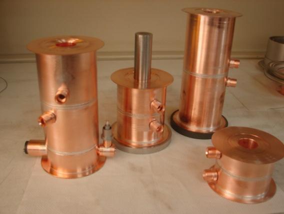
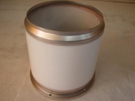
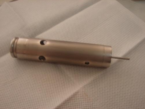
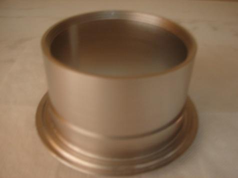
Design, Fabrication and Testing of Gun-Collector Test Module for 6 MW Peak, 24 kw Average Power, S-Band Klystron
 Available online www.ejaet.com European Journal of Advances in Engineering and Technology, 2014, 1(1): 11-15 Research Article ISSN: 2394-658X Design, Fabrication and Testing of Gun-Collector Test Module
A HIGH POWER LONG PULSE HIGH EFFICIENCY MULTI BEAM KLYSTRON
 A HIGH POWER LONG PULSE HIGH EFFICIENCY MULTI BEAM KLYSTRON A.Beunas and G. Faillon Thales Electron Devices, Vélizy, France S. Choroba DESY, Hamburg, Germany Abstract THALES ELECTRON DEVICES has developed
INTERNATIONAL JOURNAL OF ELECTRONICS AND COMMUNICATION ENGINEERING & TECHNOLOGY (IJECET)
") INTERNATIONAL JOURNAL OF ELECTRONICS AND COMMUNICATION ENGINEERING & TECHNOLOGY (IJECET) International Journal of Electronics and Communication Engineering & Technology (IJECET), ISSN 0976 6464(Print)
INTERNATIONAL JOURNAL OF ELECTRONICS AND COMMUNICATION ENGINEERING & TECHNOLOGY (IJECET) International Journal of Electronics and Communication Engineering & Technology (IJECET), ISSN 0976 6464(Print)
RF Power Generation II
 RF Power Generation II Klystrons, Magnetrons and Gyrotrons Professor R.G. Carter Engineering Department, Lancaster University, U.K. and The Cockcroft Institute of Accelerator Science and Technology Scope
Development of Multiple Beam Guns for High Power RF Sources for Accelerators and Colliders
 SLAC-PUB-10704 Development of Multiple Beam Guns for High Power RF Sources for Accelerators and Colliders R. Lawrence Ives*, George Miram*, Anatoly Krasnykh @, Valentin Ivanov @, David Marsden*, Max Mizuhara*,
Tutorial: Trak design of an electron injector for a coupled-cavity linear accelerator
 Tutorial: Trak design of an electron injector for a coupled-cavity linear accelerator Stanley Humphries, Copyright 2012 Field Precision PO Box 13595, Albuquerque, NM 87192 U.S.A. Telephone: +1-505-220-3975
Effect on Beam Current on varying the parameters of BFE and Control Anode of a TWT Electron Gun
 International Journal of Photonics. ISSN 0974-2212 Volume 7, Number 1 (2015), pp. 1-9 International Research Publication House http://www.irphouse.com Effect on Beam Current on varying the parameters of
DESIGN AND PERFORMANCE OF L-BAND AND S-BAND MULTI BEAM KLYSTRONS
 DESIGN AND PERFORMANCE OF L-BAND AND S-BAND MULTI BEAM KLYSTRONS Y. H. Chin, KEK, Tsukuba, Japan. Abstract Recently, there has been a rising international interest in multi-beam klystrons (MBK) in the
CEPC Klystron Development
 CEPC Klystron Development Zusheng Zhou On behalf of High Efficiency RF Source R&D Collaboration Institute of High Energy Physics Sep. 26, 2018, HKUST, Hong Kong 1 Outline Strategy and plan 650MHz/800kW
Pulsed Klystrons for Next Generation Neutron Sources Edward L. Eisen - CPI, Inc. Palo Alto, CA, USA
 Pulsed Klystrons for Next Generation Neutron Sources Edward L. Eisen - CPI, Inc. Palo Alto, CA, USA Abstract The U.S. Department of Energy (DOE) Office of Science has funded the construction of a new accelerator-based
Detailed Design Report
 Detailed Design Report Chapter 4 MAX IV Injector 4.6. Acceleration MAX IV Facility CHAPTER 4.6. ACCELERATION 1(10) 4.6. Acceleration 4.6. Acceleration...2 4.6.1. RF Units... 2 4.6.2. Accelerator Units...
DEVELOPMENT OF A 10 MW SHEET BEAM KLYSTRON FOR THE ILC*
 DEVELOPMENT OF A 10 MW SHEET BEAM KLYSTRON FOR THE ILC* D. Sprehn, E. Jongewaard, A. Haase, A. Jensen, D. Martin, SLAC National Accelerator Laboratory, Menlo Park, CA 94020, U.S.A. A. Burke, SAIC, San
Development of High Power Vacuum Tubes for Accelerators and Plasma Heating
 Development of High Power Vacuum Tubes for Accelerators and Plasma Heating Vishnu Srivastava Microwave Tubes Division, CSIR-Central Electronics Engineering Research Institute, Pilani-333031, Rajasthan,
UNIT-3 Part A. 2. What is radio sonde? [ N/D-16]
![UNIT-3 Part A. 2. What is radio sonde? [ N/D-16]](/thumbs/88/116973079.jpg "UNIT-3 Part A. 2. What is radio sonde? [ N/D-16]") UNIT-3 Part A 1. What is CFAR loss? [ N/D-16] Constant false alarm rate (CFAR) is a property of threshold or gain control devices that maintain an approximately constant rate of false target detections
UNIT-3 Part A 1. What is CFAR loss? [ N/D-16] Constant false alarm rate (CFAR) is a property of threshold or gain control devices that maintain an approximately constant rate of false target detections
650MHz/800kW Klystron Development at IHEP
 650MHz/800kW Klystron Development at IHEP Shilun Pei, IHEP On behalf of HERSC (High Efficiency RF Source R&D Collaboration) in China Presentation at the IAS Program on High Energy Physics January 22, 2018,
DEVELOPMENT OF X-BAND KLYSTRON TECHNOLOGY AT SLAC
 DEVELOPMENT OF X-BAND KLYSTRON TECHNOLOGY AT SLAC George Caryotakis, Stanford Linear Accelerator Center P.O. Box 4349 Stanford, CA 94309 Abstract * The SLAC design for a 1-TeV collider (NLC) requires klystrons
Design and Simulation of High Power RF Modulated Triode Electron Gun. A. Poursaleh
 Design and Simulation of High Power RF Modulated Triode Electron Gun A. Poursaleh National Academy of Sciences of Armenia, Institute of Radio Physics & Electronics, Yerevan, Armenia poursaleh83@yahoo.com
Pseudospark-sourced Micro-sized Electron Beams for High Frequency klystron Applications
 Pseudospark-sourced Micro-sized Electron Beams for High Frequency klystron Applications H. Yin 1*, D. Bowes 1, A.W. Cross 1, W. He 1, K. Ronald 1, A. D. R. Phelps 1, D. Li 2 and X. Chen 2 1 SUPA, Department
Department of Electronics and Communication Engineering Shrinathji Institute of Technology & Engineering, Nathdwara (Raj.)
") Sensitivity and Misalignment Analysis of MIG for 120 GHz, 3MW Gyrotron Manoj Kumar Sharma 1, Mahesh Kumar Porwal 2 1 M Tech-IV Semester, 2 Associate Professor Department of Electronics and Communication
Sensitivity and Misalignment Analysis of MIG for 120 GHz, 3MW Gyrotron Manoj Kumar Sharma 1, Mahesh Kumar Porwal 2 1 M Tech-IV Semester, 2 Associate Professor Department of Electronics and Communication
INFN School on Electron Accelerators. RF Power Sources and Distribution
 INFN School on Electron Accelerators 12-14 September 2007, INFN Sezione di Pisa Lecture 7b RF Power Sources and Distribution Carlo Pagani University of Milano INFN Milano-LASA & GDE The ILC Double Tunnel
X-Band Klystron Development at
 X-Band Klystron Development at SLAC Slide 1 The Beginning X-band klystron work began at SLAC in the mid to late 80 s to develop high frequency (4x SLAC s-band), high power RF sources for the linear collider
Recent ITER-Relevant Gyrotron Tests
 Journal of Physics: Conference Series Recent ITER-Relevant Gyrotron Tests To cite this article: K Felch et al 2005 J. Phys.: Conf. Ser. 25 13 View the article online for updates and enhancements. Related
Lecture 17 Microwave Tubes: Part I
 Basic Building Blocks of Microwave Engineering Prof. Amitabha Bhattacharya Department of Electronics and Communication Engineering Indian Institute of Technology, Kharagpur Lecture 17 Microwave Tubes:
These tests will be repeated for different anode positions. Radiofrequency interaction measurements will be made subsequently. A.
 VI. MICROWAVE ELECTRONICS Prof. L. D. Smullin Prof. L. J. Chu A. Poeltinger Prof. H. A. Haus L. C. Bahiana C. W. Rook, Jr. Prof. A. Bers R. J. Briggs J. J. Uebbing D. Parker A. HIGH-PERVEANCE HOLLOW ELECTRON-BEAM
4.4 Injector Linear Accelerator
 4.4 Injector Linear Accelerator 100 MeV S-band linear accelerator based on the components already built for the S-Band Linear Collider Test Facility at DESY [1, 2] will be used as an injector for the CANDLE
Defense Technical Information Center Compilation Part Notice
 UNCLASSIFIED Defense Technical Information Center Compilation Part Notice ADPO1 1739 TITLE: Modelling of Micromachined Klystrons for Terahertz Operation DISTRIBUTION: Approved for public release, distribution
This work was supported by FINEP (Research and Projects Financing) under contract
 under contract") MODELING OF A GRIDDED ELECTRON GUN FOR TRAVELING WAVE TUBES C. C. Xavier and C. C. Motta Nuclear & Energetic Research Institute, São Paulo, SP, Brazil University of São Paulo, São Paulo, SP, Brazil Abstract
MODELING OF A GRIDDED ELECTRON GUN FOR TRAVELING WAVE TUBES C. C. Xavier and C. C. Motta Nuclear & Energetic Research Institute, São Paulo, SP, Brazil University of São Paulo, São Paulo, SP, Brazil Abstract
Evaluation of Performance, Reliability, and Risk for High Peak Power RF Sources from S-band through X-band for Advanced Accelerator Applications
 Evaluation of Performance, Reliability, and Risk for High Peak Power RF Sources from S-band through X-band for Advanced Accelerator Applications Michael V. Fazio C. Adolphsen, A. Jensen, C. Pearson, D.
Low-Noise, High-Efficiency and High-Quality Magnetron for Microwave Oven
 Low-Noise, High-Efficiency and High-Quality Magnetron for Microwave Oven N. Kuwahara 1*, T. Ishii 1, K. Hirayama 2, T. Mitani 2, N. Shinohara 2 1 Panasonic corporation, 2-3-1-3 Noji-higashi, Kusatsu City,
45 MW, 22.8 GHz Second-Harmonic Multiplier for High-Gradient Tests*
 US High Gradient Research Collaboration Workshop. SLAC, May 23-25, 2007 45 MW, 22.8 GHz Second-Harmonic Multiplier for High-Gradient Tests* V.P. Yakovlev 1, S.Yu. Kazakov 1,2, and J.L. Hirshfield 1,3 1
A tapered multi-gap multi-aperture pseudospark-sourced electron gun based X-band slow wave oscillator
 A tapered multi-gap multi-aperture pseudospark-sourced electron gun based X-band slow wave oscillator N. Kumar 1, R. P. Lamba 1, A. M. Hossain 1, U. N. Pal 1, A. D. R. Phelps and R. Prakash 1 1 CSIR-CEERI,
TECHNICAL SPECIFICATION Multi-beam S-band Klystron type BT267
 TECHNICAL SPECIFICATION Multi-beam S-band Klystron type BT267 The company was created for the development and manufacture of precision microwave vacuum-electron-tube devices (VETD). The main product areas
CHAPTER 4: HIGH ENERGY X-RAY GENERATORS: LINEAR ACCELERATORS. Jason Matney, MS, PhD
 CHAPTER 4: HIGH ENERGY X-RAY GENERATORS: LINEAR ACCELERATORS Jason Matney, MS, PhD Objectives Medical electron linear accelerators (often shortened to LINAC) The Basics Power Supply Magnetron/Klystron
Final Report. U.S. Department of Energy Grant Number DE-FG02-04ER83916
 Development of a 200 MHz Multiple Beam Klystron Final Report U.S. Department of Energy Grant Number DE-FG02-04ER83916 July 2004 - March 2005 Calabazas Creek Research, Inc. 20937 Comer Drive Saratoga, CA
NEW METHOD FOR KLYSTRON MODELING
 NEW METHOD FOR KLYSTRON MODELING Y. H. Chin, KEK, 1-1 Oho, Tsukuba-shi, Ibaraki-ken, 35, Japan Abstract We have developed a new method for a realistic and more accurate simulation of klystron using the
CPI Gyrotrons For Fusion EC Heating
 CPI Gyrotrons For Fusion EC Heating H. Jory, M. Blank, P. Borchard, P. Cahalan, S. Cauffman, T. S. Chu, and K. Felch CPI, Microwave Power Products Division 811 Hansen Way, Palo Alto, CA 94303, USA e-mail:
A SHEET-BEAM KLYSTRON PAPER DESIGN
 SLAC-PUB-8967 A SHEET-BEAM KLYSTRON PAPER DESIGN G. Caryotakis Stanford Linear Accelerator Center, Stanford University, Stanford Ca. 94309 Abstract What may be the first detailed cold test and computer
Development of klystrons with ultimately high - 90% RF power production efficiency
 Development of klystrons with ultimately high - 90% RF power production efficiency A. Baikov (MUFA), I. Syratchev (CERN), C. Lingwood, D. Constable (Lancaster University) Introduction FCC has high power
SLAC-PUB-2380 August 1979 (A)
") 1979 LINEAR ACCELERATOR CONFERENCE RF SOURCES DEVELOPMENTS* Jean V. Lebacqz Stanford Linear Accelerator Center Stanford University, Stanford, California 94305 SLAC-PUB-2380 August 1979 (A) Abstract The
1979 LINEAR ACCELERATOR CONFERENCE RF SOURCES DEVELOPMENTS* Jean V. Lebacqz Stanford Linear Accelerator Center Stanford University, Stanford, California 94305 SLAC-PUB-2380 August 1979 (A) Abstract The
RF Solutions for Science.
 RF Solutions for Science www.thalesgroup.com State-of-the-art RF sources for your scientific needs High-power klystrons HIGH KLYSTRONS WITH RF LONG PULSE above 50 μs Thales has been one of the leading
ADVANCED HIGH-POWER MICROWAVE VACUUM ELECTRON DEVICE DEVELOPMENT
 ADVANCED HIGH-POWER MICROWAVE VACUUM ELECTRON DEVICE DEVELOPMENT H. P. Bohlen, Inc., Palo Alto, CA Abstract The microwave 1 power requirements of particle accelerators have been growing almost exponentially
Particle-in-cell simulation study of PCE-gun for different hollow cathode aperture sizes
 Indian Journal of Pure & Applied Physics Vol. 53, April 2015, pp. 225-229 Particle-in-cell simulation study of PCE-gun for different hollow cathode aperture sizes Udit Narayan Pal a,b*, Jitendra Prajapati
IOT RF Power Sources for Pulsed and CW Linacs
 LINAC 2004 Lübeck, August 16 20, 2004 IOT RF Power Sources H. Bohlen, Y. Li, Bob Tornoe Communications & Power Industries Eimac Division, San Carlos, CA, USA Linac RF source property requirements (not
Investigation of Radio Frequency Breakdown in Fusion Experiments
 Investigation of Radio Frequency Breakdown in Fusion Experiments T.P. Graves, S.J. Wukitch, I.H. Hutchinson MIT Plasma Science and Fusion Center APS-DPP October 2003 Albuquerque, NM Outline Multipactor
Low Frequency Gyrotrons for Fusion
 13th Joint Workshop on Electron Cyclotron Emission and Electron Cyclotron Resonance Heating Nizhny Novgorod, Russia May 17-20, 2004 РАН Low Frequency Gyrotrons for Fusion НПП ГИКОМ V.E. Zapevalov, Yu.K.
THE X-BAND KLYSTRON PROGRAM AT SLAC'
 SLAC-PUB-7 146 April 1996 THE X-BAND KLYSTRON PROGRAM AT SLAC' George Caryotakis ' Stanford Linear Accelerator Center Stanford University, Stanford, CA 9439 The X-band r f source development at SLAC can
TOSHIBA Industrial Magnetron E3328
 TOSHIBA E3328 is a fixed frequency continuous wave magnetron intended for use in the industrial microwave heating applications. The average output power is 3kW in the frequency range from 2450 to 2470
TEST RESULTS OF THE 84 GHZ / 200 KW / CW GYROTRON
 TEST RESULTS OF THE 84 GHZ / 200 KW / CW GYROTRON V.I. Belousov, A.A.Bogdashov, G.G.Denisov, V.I.Kurbatov, V.I.Malygin, S.A.Malygin, V.B.Orlov, L.G.Popov, E.A.Solujanova, E.M.Tai, S.V.Usachov Gycom Ltd,
Klystron Tubes. Two forms of such a device, also called linear beam klystron, are given in the following figure.
 Klystron Tubes Go to the klystron index The principle of velocity-variation, first used in Heil oscillators, was also used in other microwave amplifying and oscillating tubes. The application for klystron
High Brightness Injector Development and ERL Planning at Cornell. Charlie Sinclair Cornell University Laboratory for Elementary-Particle Physics
 High Brightness Injector Development and ERL Planning at Cornell Charlie Sinclair Cornell University Laboratory for Elementary-Particle Physics June 22, 2006 JLab CASA Seminar 2 Background During 2000-2001,
RF Design of the LCLS Gun C.Limborg, Z.Li, L.Xiao, J.F. Schmerge, D.Dowell, S.Gierman, E.Bong, S.Gilevich February 9, 2005
 RF Design of the LCLS Gun C.Limborg, Z.Li, L.Xiao, J.F. Schmerge, D.Dowell, S.Gierman, E.Bong, S.Gilevich February 9, 2005 Summary Final dimensions for the LCLS RF gun are described. This gun, referred
Optimization of a triode-type cusp electron gun for a W-band gyro-twa
 Optimization of a triode-type cusp electron gun for a W-band gyro-twa Liang Zhang, 1, a) Craig R. Donaldson, 1 and Wenlong He 1 Department of Physics, SUPA, University of Strathclyde, Glasgow, G4 0NG,
RF plans for ESS. Morten Jensen. ESLS-RF 2013 Berlin
 RF plans for ESS Morten Jensen ESLS-RF 2013 Berlin Overview The European Spallation Source (ESS) will house the most powerful proton linac ever built. The average beam power will be 5 MW which is five
CEBAF 8 kw CW KLYSTRON SPECIFICATION EE0043, Rev. H January 15, 1998
 Thomas Jefferson National Laboratory Specification CEBAF 8 kw CW KLYSTRON SPECIFICATION EE0043, Rev. H January 15, 1998 Approved by: Richard Nelson Date William Merz Date Claus Rode Date EE0044, Rev. H
Experience with the Cornell ERL Injector SRF Cryomodule during High Beam Current Operation
 Experience with the Cornell ERL Injector SRF Cryomodule during High Beam Current Operation Matthias Liepe Assistant Professor of Physics Cornell University Experience with the Cornell ERL Injector SRF
Empirical Model For ESS Klystron Cathode Voltage
 Empirical Model For ESS Klystron Cathode Voltage Dave McGinnis 2 March 2012 Introduction There are 176 klystrons in the superconducting portion of ESS linac. The power range required spans a factor of
w. B. HERRMANNSFELDT and K. R. EPPLEY
 Particle Accelerators, 199, Vol. 3, pp. 197-29 Reprints available directly from the publisher Photocopying permitted by license only 199 Gordon and Breach, Science Publishers, Inc. Printed in the United
Performance of a DC GaAs photocathode gun for the Jefferson lab FEL
 Nuclear Instruments and Methods in Physics Research A 475 (2001) 549 553 Performance of a DC GaAs photocathode gun for the Jefferson lab FEL T. Siggins a, *, C. Sinclair a, C. Bohn b, D. Bullard a, D.
Next Linear Collider. The 8-Pack Project. 8-Pack Project. Four 50 MW XL4 X-band klystrons installed on the 8-Pack
 The Four 50 MW XL4 X-band klystrons installed on the 8-Pack The Demonstrate an NLC power source Two Phases: 8-Pack Phase-1 (current): Multi-moded SLED II power compression Produce NLC baseline power: 475
SLS RF operation report 2003
 SLS RF operation report 2003 M. Pedrozzi, Jean-Yves Raguin Paul Scherrer Institute, 5232 Villigen PSI, Switzerland SUMMARY LINAC report SR Superconducting Third Harmonic system report SR 500 MHz system
X-Band klystron development at the Stanford Linear Accelerator Center
 SLAC-PUB-8346 March 2000 X-Band klystron development at the Stanford Linear Accelerator Center D. Sprehn, G. Caryotakis, E. Jongewaard, R. M. Phillips, and A. Vlieks Stanford Linear Accelerator Center
SECTION I INTRODUCTION
 SECTION I INTRODUCTION This handbook analyzes the operation of EIMAC power grid tubes and provides design and application information to assist the user of these tubes to achieve long tube life, maximum
The PEFP 20-MeV Proton Linear Accelerator
 Journal of the Korean Physical Society, Vol. 52, No. 3, March 2008, pp. 721726 Review Articles The PEFP 20-MeV Proton Linear Accelerator Y. S. Cho, H. J. Kwon, J. H. Jang, H. S. Kim, K. T. Seol, D. I.
Teltron Delection Tube D
 Teltron Delection Tube D 1011119 Overview The electron-beam deflection tube is intended for investigating the deflection of electron beams in electrical and magnetic fields. It can be used to estimate
IOT OPERATIONAL EXPERIENCE ON ALICE AND EMMA AT DARESBURY LABORATORY
 IOT OPERATIONAL EXPERIENCE ON ALICE AND EMMA AT DARESBURY LABORATORY A. Wheelhouse ASTeC, STFC Daresbury Laboratory ESLS XVIII Workshop, ELLETRA 25 th 26 th November 2010 Contents Brief Description ALICE
KLYSTRON GUN ARCING AND MODULATOR PROTECTION
 SLAC-PUB-10435 KLYSTRON GUN ARCING AND MODULATOR PROTECTION S.L. Gold Stanford Linear Accelerator Center (SLAC), Menlo Park, CA USA Abstract The demand for 500 kv and 265 amperes peak to power an X-Band
THE NEXT LINEAR COLLIDER TEST ACCELERATOR: STATUS AND RESULTS * Abstract
 SLAC PUB 7246 June 996 THE NEXT LINEAR COLLIDER TEST ACCELERATOR: STATUS AND RESULTS * Ronald D. Ruth, SLAC, Stanford, CA, USA Abstract At SLAC, we are pursuing the design of a Next Linear Collider (NLC)
3 cerl. 3-1 cerl Overview. 3-2 High-brightness DC Photocathode Gun and Gun Test Beamline
 3 cerl 3-1 cerl Overview As described before, the aim of the cerl in the R&D program includes the development of critical components for the ERL, as well as the construction of a test accelerator. The
Operating Experience and Reliability Improvements on the 5 kw CW Klystron at Jefferson Lab
 Operating Experience and Reliability Improvements on the 5 kw CW Klystron at Jefferson Lab Richard Walker & Richard Nelson Jefferson Lab, Newport News VA Jefferson Lab is a $600M Department of Energy facility
Development of high power gyrotron and EC technologies for ITER
 1 Development of high power gyrotron and EC technologies for ITER K. Sakamoto 1), K.Kajiwara 1), K. Takahashi 1), Y.Oda 1), A. Kasugai 1), N. Kobayashi 1), M.Henderson 2), C.Darbos 2) 1) Japan Atomic Energy
Design of a 50 MW Klystron at X-Band*
 SLAC-PUB-954676 July 1995 Background Eight Next Linear Collider (NLC) prototype klystrons, known as the XC-series Design of a 50 MW Klystron at X-Band* klystrons, have been evaluated at SLAC with a goal
Review of Diamond SR RF Operation and Upgrades
 Review of Diamond SR RF Operation and Upgrades Morten Jensen on behalf of Diamond Storage Ring RF Group Agenda Stats X-ray and LN2 pressure results Cavity Failure Conditioning in the RFTF Cavity Simulations
The Elettra Storage Ring and Top-Up Operation
 The Elettra Storage Ring and Top-Up Operation Emanuel Karantzoulis Past and Present Configurations 1994-2007 From 2008 5000 hours /year to the users 2010: Operations transition year Decay mode, 2 GeV (340mA)
Status of BESSY II and berlinpro. Wolfgang Anders. Helmholtz-Zentrum Berlin for Materials and Energy (HZB) 20th ESLS-RF Meeting
 20th ESLS-RF Meeting") Status of BESSY II and berlinpro Wolfgang Anders Helmholtz-Zentrum Berlin for Materials and Energy (HZB) 20th ESLS-RF Meeting 16.-17.11.2016 at PSI Outline BESSY II Problems with circulators Landau cavity
Status of BESSY II and berlinpro Wolfgang Anders Helmholtz-Zentrum Berlin for Materials and Energy (HZB) 20th ESLS-RF Meeting 16.-17.11.2016 at PSI Outline BESSY II Problems with circulators Landau cavity
Commissioning the TAMUTRAP RFQ cooler/buncher. E. Bennett, R. Burch, B. Fenker, M. Mehlman, D. Melconian, and P.D. Shidling
 Commissioning the TAMUTRAP RFQ cooler/buncher E. Bennett, R. Burch, B. Fenker, M. Mehlman, D. Melconian, and P.D. Shidling In order to efficiently load ions into a Penning trap, the ion beam should be
A New 4MW LHCD System for EAST
 1 EXW/P7-29 A New 4MW LHCD System for EAST Jiafang SHAN 1), Yong YANG 1), Fukun LIU 1), Lianmin ZHAO 1) and LHCD Team 1) 1) Institute of Plasma Physics, Chinese Academy of Sciences, Hefei, China E-mail
High-power klystrons. The benchmark in scientific research. State-of-the-art RF sources for your accelerator
 > High- klystrons The benchmark in scientific research State-of-the-art RF sources for your accelerator Thales has been one of the leading manufacturers of RF and microwave sources for decades, and is
RF Upgrades & Experience At JLab. Rick Nelson
 RF Upgrades & Experience At JLab Rick Nelson Outline Background: CEBAF / Jefferson Lab History, upgrade requirements & decisions Progress & problems along the way Present status Future directions & concerns
Multipaction Breakdown Prediction of Passive Microwave Devices with CST Particle-Studio
 Multipaction Breakdown Prediction of Passive Microwave Devices with CST Particle-Studio José R. Montejo Garai (1), Carlos A. Leal (1), Jorge A. Ruiz Cruz (2) Jesús M. Rebollar Machaín (1) (1) Dpto. de
CATHODE-RAY OSCILLOSCOPE (CRO)
") CATHODE-RAY OSCILLOSCOPE (CRO) I N T R O D U C T I O N : The cathode-ray oscilloscope (CRO) is a multipurpose display instrument used for the observation, measurement, and analysis of waveforms by plotting
CATHODE-RAY OSCILLOSCOPE (CRO) I N T R O D U C T I O N : The cathode-ray oscilloscope (CRO) is a multipurpose display instrument used for the observation, measurement, and analysis of waveforms by plotting
M.G.M.'S COLLEGE OF ENGG. NANDED. DEPT OF ECT QUESTION BANK NO:- 1 CLASS:-BE(ECT) SUB:-DVD DATE: / /...
 SUB:-DVD DATE: / /...") M.G.M.'S COLLEGE OF ENGG. NANDED. DEPT OF ECT QUESTION BANK NO:- 1 CLASS:-BE(ECT) SUB:-DVD DATE: / /... 1) Explain historical perspective & issues in digital design. 2) Explain trends in digital design.
M.G.M.'S COLLEGE OF ENGG. NANDED. DEPT OF ECT QUESTION BANK NO:- 1 CLASS:-BE(ECT) SUB:-DVD DATE: / /... 1) Explain historical perspective & issues in digital design. 2) Explain trends in digital design.
Available online Journal of Scientific and Engineering Research, 2018, 5(5): Research Article
: Research Article") Available online www.jsaer.com, 218, 5(5):247-251 Research Article ISSN: 2394-263 CODEN(USA): JSERBR Optimization of Klystron Cavity Using Dielectric Materials Digima Mustapha 1 *, Ibrahim Mustapha 2,
Available online www.jsaer.com, 218, 5(5):247-251 Research Article ISSN: 2394-263 CODEN(USA): JSERBR Optimization of Klystron Cavity Using Dielectric Materials Digima Mustapha 1 *, Ibrahim Mustapha 2,
18 GHz, 2.2 kw KLYSTRON GENERATOR GKP 24KP 18GHz WR62 3x400V
 18 GHz, 2.2 kw KLYSTRON GENERATOR GKP 24KP 18GHz WR62 3x400V With its characteristics of power stability whatever the load, very fast response time when pulsed (via external modulated signal), low ripple,
Diamond RF Status (RF Activities at Daresbury) Mike Dykes
 Mike Dykes") Diamond RF Status (RF Activities at Daresbury) Mike Dykes ASTeC What is it? What does it do? Diamond Status Linac Booster RF Storage Ring RF Summary Content ASTeC ASTeC was formed in 2001 as a centre of
Diamond RF Status (RF Activities at Daresbury) Mike Dykes ASTeC What is it? What does it do? Diamond Status Linac Booster RF Storage Ring RF Summary Content ASTeC ASTeC was formed in 2001 as a centre of
Spear3 RF System Sam Park 11/06/2003. Spear3 RF System. High Power Components Operation and Control. RF Requirement.
 Spear3 RF System RF Requirement Overall System High Power Components Operation and Control SPEAR 3 History 1996 Low emittance lattices explored 1996 SPEAR 3 proposed 11/97 SPEAR 3 design study team formed
RF POWER GENERATION FOR FUTURE LINEAR COLLIDERS* 1. Introduction
 SLAC-PUB-5282 June 1990 (A) RF POWER GENERATION FOR FUTURE LINEAR COLLIDERS* W. R. Fowkes, M. A. Allen, R. S. Callin, G. Caryotakis, K. R. Eppley, K. S. Fant, Z. D. Farkas, J. Feinstein, K. Ko, R. F. Koontz,
CHAPTER 4 OSCILLOSCOPES
 CHAPTER 4 OSCILLOSCOPES 4.1 Introduction The cathode ray oscilloscope generally referred to as the oscilloscope, is probably the most versatile electrical measuring instrument available. Some of electrical
K800 RF AMPLIFIER TUBE UPGRADE
 R. F. Note 107 John Vincent August 5, 1988 K800 RF AMPLIFIER TUBE UPGRADE Contents: 1. Introduction 2. RCA 4648 Operating Experience and Evaluation. 3. Tube Selection Criteria 4. Cost and Availability
RF considerations for SwissFEL
 RF considerations for H. Fitze in behalf of the PSI RF group Workshop on Compact X-Ray Free Electron Lasers 19.-21. July 2010, Shanghai Agenda Introduction RF-Gun Development C-band development Summary
J/NLC Progress on R1 and R2 Issues. Chris Adolphsen
 J/NLC Progress on R1 and R2 Issues Chris Adolphsen Charge to the International Linear Collider Technical Review Committee (ILC-TRC) To assess the present technical status of the four LC designs at hand,
14 GHz, 2.2 kw KLYSTRON GENERATOR GKP 22KP 14GHz WR62 3x400V
 14 GHz, 2.2 kw KLYSTRON GENERATOR GKP 22KP 14GHz WR62 3x400V With its characteristics of power stability independent of the load, very fast response time when pulsed (via external modulated signal), low
DEPARTMENT OF ELECTRONICS AND COMMUNICATION ENGINEERING QUESTION BANK
 DEPARTMENT OF ELECTRONICS AND COMMUNICATION ENGINEERING QUESTION BANK SUBJECT NAME : MICROWAVE ENGINEERING UNIT I BASIC MICROWAVE COMPONENTS 1. State Faraday s rotation law. 2. State the properties of
Dark current and multipacting trajectories simulations for the RF Photo Gun at PITZ
 Dark current and multipacting trajectories simulations for the RF Photo Gun at PITZ Introduction The PITZ RF Photo Gun Field simulations Dark current simulations Multipacting simulations Summary Igor Isaev
Experimental Results of the Coaxial Multipactor Experiment. T.P. Graves, B. LaBombard, S.J. Wukitch, I.H. Hutchinson PSFC-MIT
 Experimental Results of the Coaxial Multipactor Experiment T.P. Graves, B. LaBombard, S.J. Wukitch, I.H. Hutchinson PSFC-MIT Summary A multipactor discharge is a resonant condition for electrons in an
Accelerator Instrumentation RD. Monday, July 14, 2003 Marc Ross
 Monday, Marc Ross Linear Collider RD Most RD funds address the most serious cost driver energy The most serious impact of the late technology choice is the failure to adequately address luminosity RD issues
Summary of the 1 st Beam Line Review Meeting Injector ( )
") Summary of the 1 st Beam Line Review Meeting Injector (23.10.2006) 15.11.2006 Review the status of: beam dynamics understanding and simulations completeness of beam line description conceptual design of
Summary of the 1 st Beam Line Review Meeting Injector (23.10.2006) 15.11.2006 Review the status of: beam dynamics understanding and simulations completeness of beam line description conceptual design of
KEKB INJECTOR LINAC AND UPGRADE FOR SUPERKEKB
 KEKB INJECTOR LINAC AND UPGRADE FOR SUPERKEKB S. Michizono for the KEK electron/positron Injector Linac and the Linac Commissioning Group KEK KEKB injector linac Brief history of the KEK electron linac
Linac 4 Instrumentation K.Hanke CERN
 Linac 4 Instrumentation K.Hanke CERN CERN Linac 4 PS2 (2016?) SPL (2015?) Linac4 (2012) Linac4 will first inject into the PSB and then can be the first element of a new LHC injector chain. It will increase
150-MW S-Band Klystron Program at the Stanford Linear Accelerator Center1
 SLAC Pub 7232 July 1996 4 15-MW S-Band Klystron Program at the Stanford Linear Accelerator Center1 D. SPREHN, G. CARYOTAKS, and R. M. PHLLPS Stanford Linear Accelerator Center Stanford Universiw, Stanford,
STATUS OF THE SWISSFEL C-BAND LINEAR ACCELERATOR
 Proceedings of FEL213, New York, NY, USA STATUS OF THE SWISSFEL C-BAND LINEAR ACCELERATOR F. Loehl, J. Alex, H. Blumer, M. Bopp, H. Braun, A. Citterio, U. Ellenberger, H. Fitze, H. Joehri, T. Kleeb, L.