TOURMASTER QUICK OPERATION
|
|
|
- Gordon Booker
- 5 years ago
- Views:
Transcription
1
2 TOURMASTER QUICK OPERATION Press the Back key to reach the top menu- the LCD shows. Softkeys are shown in italics e.g.: setup. SETTING DMX PATCH ADDRESSES AND LOCKING THE KEYS To change the DMX address of any dimmer in any bin: 1. From the top menu, press Menu three times to arrive at the DMX Patch Address menu. 2. Press 5/ 6 to adjust the address. Press3/4to set 10s, 100s, or the dimmer or bin number. 3. Press Back to return to the top menu: the screen shows Changes saved to flash memory. 4. To lock the keypad, hold3+4+5for 2 seconds. To unlock the keypad, hold3+4+6for 8 seconds. SETTING DMX FAIL MODE To set the DMX Fail Mode of all bins in the cabinet, to either Fade to Black or Hold DMX levels : 1. From the top menu, press Menu twice, select DMX fail mode setup, press Menu. 2. Use 5/ 6 to select the mode, then press on (4) to set the mode On. 3. Press times (Menu) to enter the DMX Fail Fade Delay/Time menu: use the arrow keys to edit the times. 4. Press Back to return to the top menu: the screen shows Changes saved to flash memory. SETTING DIMMER PARAMETERS To set Test, Min, Max, Non-Dim, Off levels, Curve, Proportional levels, or Softstart time for each dimmer in each bin: 1. From the top menu, press Menu twice, select Dimmer & bin setup, press setup (Menu key). 2. Use5/ 6 keys to select the parameter to adjust, then press setup (Menu key). 3. Use3/4keys to select the dimmer, 5/ 6to adjust parameters, with softkey all for all dimmers in all bins. 4. Press Back to return to the top menu: the screen shows Changes saved to flash memory. RESETTING TOURMASTER BIN PARAMETERS To reset the dimmer parameters of each bin: 1. From the top menu, press Menu twice, select Dimmer & bin setup, press setup (Menu). 2. Use 5/ 6to select Reset Commands, press setup, select Reset Dimmers + DMX, press select. 3. Use 5/ 6and 3/4keys to select Bin number and set Bin DMX Start address, press OK (Menu). 4. The screen shows Resetting all Dimmer and DMX parameters. Repeat step 3 to set other bins
3 TOURMASTER TABLE OF CONTENTS TOURMASTER QUICK OPERATION...1 Setting DMX patch addresses and locking the keys 1 Setting DMX fail mode 1 Setting dimmer parameters 1 Resetting Tourmaster bin parameters 1 TOURMASTER INTRODUCTION...3 TOURMASTER CONTROL PANEL LEGEND...4 TOURMASTER OVERVIEW...5 Dimmer modules 5 Control panel 5 Power supply 7 MCB Protection 7 hardpatch 7 power sockets 7 DMX softpatch 8 Remote control 8 Dimmer parameters 8 Dimmer settings priority 11 Level displays 12 Resetting dimmer default parameters 12 TOURMASTER DEFAULT PARAMETERS TOURMASTER INITIAL SETUP Unlocking the keys 15 Locking the keys 15 Reading the number of dimmers in each bin 15 Setting the cabinet ID 15 Setting bins to DMX universe A or B 17 SETTING AND DISPLAYING DIMMER PARAMETERS.19 Setting all dimmer parameters to defaults 19 Setting DMX patch addresses 19 Setting DMX fail mode and DMX fail mode times 21 Testing or setting dimmer levels 21 Setting dimmer minimum and maximum levels 23 Setting non-dim levels 23 Setting off levels 25 Setting dimmer curves 25 Setting proportional levels 25 Setting soft-start times 27 Saving a worklights scene 27 TOURMASTER LEVELS AND ERROR DISPLAYS...29 Displaying bin DMX levels 29 Displaying bin final dimmer levels 29 Displaying bin mains voltage and frequency 29 Displaying bin temperatures/fan test 31 Displaying bin temperature history 31 Displaying TLNet receive and transmit data 31 Status displays 33 ETHERNET OPTION...35 Setting the DMX-over-Ethernet universes 35 Setting the IP Address 35 Setting the MAC Address 35 MAINTENANCE...36 SPECIFICATIONS...37 DIMENSIONS...39 GLOSSARY...40 INDEX...42
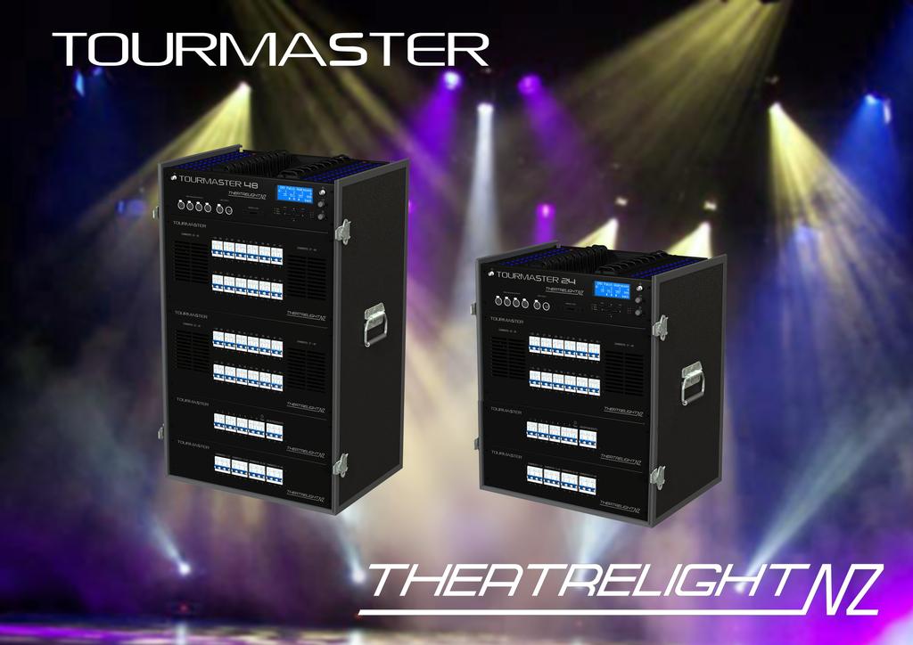
4 TOURMASTER INTRODUCTION TOURMASTER OPERATION 3 The Theatrelight Tourmaster is a general purpose dimmer cabinet designed for touring and location. The Tourmaster design is based on software and hardware designs already well proven in the Theatrelight products Nebula a 3u high rackmounting professional dimmer pack, and Meteor a wall mounting Stage or Environmental dimmer. Users familiar with these products will find the menu system and key setup of the Tourmaster intuitive and easy to understand. The new design uses distributed multiple micro-processors for maximum reliability. Additionally the main CPU needs no expensive back-up system when operating on DMX in the unlikely event of total failure of the main CPU, all dimmers continue operation without interruption to the show. The switch-mode power supplies have a proven history in Theatrelight s Nebula and RackPack II designs. The built-in DMX splitter presents only one, 1/10th standard load to a DMX cable, allowing many Tourmaster cabinets on a single DMX cable. The Tourmaster can also be fitted with DMX-over-Ethernet communication systems for use with Artnet standard control panels, an optional RS485 system for use with remote keyplate lighting controllers, or an SD Crad logging system. The Tourmaster is available in standard 24 and 48 channel versions. Tourmaster firmware is available in a number of different configurations, and with different communications hardware and software according to customer request. TOURMASTER FEATURES Simple menu system with large 4 line, 20 character auto dimming LCD display at eye height Every dimmer may be soft-patched to any DMX address. Every dimmer may be set to its own Min, Max, Off, Proportional, Test level, Soft-start Time, and Dimmer Curve All dimmer parameters held in non-volatile flash memory Temperature controlled cooling fans for low acoustic noise and long life Redundant main set-up CPU, and multiple, distributed microprocessors, 1 CPU for every 12 dimmers High reliability power supplies, input 90 volts AC to 265 Volts AC, frequency from 45 to 65 Hertz Isolated, floating DMX input, 1/10th standard load for the whole cabinet Built DMX splitter for supplying DMX to other dimmers cabinets or movijng light systems Optional hard patch system Tourmaster can be suplied with mains input and output connectors to customer specification
5 4 TOURMASTER OPERATION TOURMASTER CONTROL PANEL LEGEND G TOURMASTER 48 H DMX A ISOLATED OUTPUTS DMX A IN/OUT MEMORY CARD C A D LCD G E F I B A: Large clear 4 row x 20 character Blue LCD display with white LED backlight. B: Simple keyboard and easy to understand menu system allow quick setup of all dimmer functions and parameters. C: The DMX LED shows the presence of DMX signal, and flashes continually on a DMX error in any dimmer bin. The TEMP LED flashes to warn of over-temperature conditions. The Status LED indicates active communications with the dimmer bins D: A B C LEDs indicate presence of mains power on each phase in each dimmer bin. Each LED flashes continually on a undervoltage error in any dimmer bin E: Potentiometer control of LCD brightness. The LEDs and key brightness is also controlled. F: Potentiometer control of Gooseneck lights brightness. G: Gooseneck light sockets. Other gooseneck light sockets are fitted on the patch panel and back panel. H: Built-in DMX splitter with 4 isolated outputs. I: SD card socket for data logging (option).
6 TOURMASTER OPERATION 5 TOURMASTER OVERVIEW The following description provides an overview of the capabilities of the Tourmaster. DIMMER MODULES The Tourmaster is supplied as standard in either 24 or 48 channels. The 24 channel Tourmaster has a single dimmer module of 24 dimmers while the 48 channel Tourmaster has 2 modules. Each 24 dimmer module contains 2 dimmer Bins of 12 dimmers, each bin with its own SCR/Fan unit and its own CPU and power supply. All dimmer parameters (such as min and max levels etc) are set in each bin CPU by the keys and LCD of central microprocessor on the top control panel. After initial setup each bin CPU runs its own 12 dimmers from DMX independently of the central CPU. SCR/Fan Unit The SCR/Fan unit is self-contained and mounted on sliders with front access for ease of servicing. The SCR unit is made from heavy aluminium extrusion, finned for maximum transfer of heat from its own fan, Power semiconductors and filter chokes are thermally connected to the finned extrusion for cool operation and maximum reliability. For maximum cooling efficiency, air is sucked in through the patch panel well, and exhausted through each SCR module and out through louvres in the front panel. The speed of all the fans is controlled by the maximum temperature read from the dual thermal sensors on each SCR unit: all fans are set to run at the same speed for correct airflow direction. Tourmaster cabinets should be mounted in a position where fan noise cannot interfere with a performance. The standard dimmer type is a 4kw SCR dimmer with filter chokes suited for touring work. Other specification filter chokes up to TV Studio standards can be supplied. CONTROL PANEL Setup of all parameters of all dimmers in the Tourmaster is effected from a central keyboard and LCD. This central microprocessor is only required for dimmer set-up once all dimmer parameters have been set in each bin CPU it cannot affect the proper operation of the dimmers. Power for the central CPU is contributed from each of the dimmer bin power supplies, and protected by the three control MCBs located in the power distribution section at the lower front panel. Control Panel LCD display The large 4 line, 20 character per line Blue LCD display has white LED auto-dimming backlighting, giving excellent contrast and readability under all lighting conditions. The brightness of the display goes to full at the first key press, and reduces after 10 minutes. The display is easily visible across the width of a standard dimmer room. A brightness control is sited to right of the display.
7 6 TOURMASTER OPERATION Control Panel Keys The Control Panel has a small keypad of 6 keys. The key operation is designed to be simple and to allow the operator fast and easy access to all dimmer functions in all bins. The Menu key steps down through the menu tree, while the Back key steps back. The keys Up5, Down6, Left3, and Right4are used for navigation and to adjust values. In most menus the function of the key is indicated in the bottom line of the LCD ( softkey ), making for easy understanding. If a value is changed (such as the DMX Address), the new value will be saved automatically to flash memory after a timeout period of 10 minutes. Alternatively the new value can be saved immediately by pressing the Back key to return to the top menu. The keys may also be locked to prevent unauthorised operation. Control Panel LEDs Front panel LEDs are provided for display of DMX signal, over-temperature indication, remote control codes, and proper mains presence on Phases A B and C. All LEDs are initially turned on full at power up, before assuming their correct status. DMX LED The Green DMX LED is continually On if the DMX (or DMX over Ethernet) signals to all bins are free of errors. The LED flashes continuously if any bin DMX signal is disconnected, or if there are errors during communication with that bin. Status LED The Amber Status LED indicates communications activity with the bins, or the Remote control communications network (dependent on software version). Phase A B C LEDs Green LEDs A B C indicate correct presence of mains power on each phase. The LEDs flash continuously if any bin phase voltage is low, or if there are errors during communication with that bin. Temperature/Error LED The red temperature/error LED is normally Off. In the event that the temperature of any dimmer module in the Tourmaster cabinet reaches 50 degrees Centigrade, the LED blinks rapidly. DMX inputs and splitter A built in DMX512 splitter is provided to re-shape and buffer the received DMX, and to prevent issues caused by earth loops and heavy loading. Each Tourmaster cabinet has two DMX inputs A and B. Each dimmer bin of 12 dimmers can be selected to either DMX universe A or B from the main keypad. Memory Card Logger In Tourmasters fitted with special firmware, an SD card reader can log mains voltage and frequency over time.
8 Gooseneck light sockets TOURMASTER OPERATION 7 The front panel is fitted with two BNC sockets for gooseneck panel lights. Two additional sockets are provided on the back panel, and two more on the patch panel (if fitted). Gooseneck dimmer control The front panel has a knob for dimming the gooseneck panel lights. Worklights power sensor A worklights power sensor (IEC connector) is fitted on the back panel and is normally plugged into the stage working lights circuit. If the stage worklghts are switched on, then the Tourmaster will fade up a Worklight scene- a previously recorded DMX snapshot held in each dimmer bin. When the worklights are switched off, the Worklight scene levels are faded to black. Worklight scene levels add to the current DMX levels on a Highest take Precedence (HTP) basis. POWER SUPPLY The Tourmaster is designed to be supplied with power mains of 90 to 265 volts AC, 3 phase and Neutral, 45 to 65 Hz. The Tourmaster cannot be used in a 3 Phase Delta connection (i.e. with no Neutral wire). Each Tourmaster cabinet must be properly earthed. The standard mains power connectors is PowerLock, with through connector as an option MCB PROTECTION Each 12 chn dimmer bin is supplied by a 3 phase 80 amp, 10ka MCB, while each dimmer channel is protected by a 20 amp, 6ka MCB. Additionaly the Independent master power is supplied by a 3 phase 80 amp, 10ka MCB, splitting to 8 single phase, 13 amp, 6ka MCBs. Power for the Goose neck lights, DMX splitter, and Test sockets is via by single phase 13 amp, 6ka MCB. RCD mains MCBs can be supplied on request. HARDPATCH The Tourmaster can be optionally supplied with a built hard patching system using 20 amp rated patch plugs, stackable two high (with patch cover on). The patch cords store convenienlty in a centre well when not in use. POWER SOCKETS The Tourmaster 48 is fitted as standard with 96 outputs through 16 Socapex connectors- each channel can be hard patched to any dimmer, test, or independent (non-dim) power supply. In addition there are 12 independent power sockets, each of which can be patched to any dimmer, test, or independent (non-dim) power supply.
9 8 TOURMASTER OPERATION DMX SOFTPATCH Each Tourmaster cabinet has two DMX inputs A and B. Each dimmer bin of 12 channels can be selected to one of tthese two DMX universes by software control from the central keyboard. DMX Patch Addresses Every dimmer in the cabinet may be set to its own DMX address from the main keyboard. Using this built in patch system allows great flexibility in matching dimmers to loads- if a large number of loads are required to be controlled together, any number of dimmers (even all dimmers in the cabinet) can be controlled by a single DMX channel. The DMX address may be set to be any number between 1 and 4096 to ease the task of calculating dimmer numbers in multiple DMX universe systems. DMX Fail Modes The Tourmaster provides two options in case the DMX signal fails, or the DMX signal is turned off, as for example when the control panel is turned off at the end of a show. The options are Fade to blackout- after a delay time, all dimmers in the cabinet are faded to blackout. Both the delay time and the fade time are programmable from Instant to 30 minutes. Hold last DMX levels- the last valid DMX levels are held until the next valid DMX input, or the cabinet is switched off REMOTE CONTROL The Tourmaster dimmers may also be optionally controlled by RS-485 signal from Theatrelight wallplates, or Ethernet when supplied with optional firmware. DIMMER PARAMETERS Each dimmer channel in the Tourmaster has a number of parameters which may be set individually. As incorrect setting of these parameters can prevent the dimmers from working as expected, care must be taken when setting them up. Test and Set Dimmer levels Normally each dimmer is controlled from the DMX line (or RS-485/Ethernet line where fitted). However the Test/Set options allow each dimmer to be set to a level which overrides all control inputs. This override level can be set to any level between Off and Full. An "All" function allows all Test/Set levels in the cabinet to be set at the same time. Each dimmer can also be flashed instantly to Full for identification. The "All" function may also be used with Flash, allowing all dimmers in a bin to be flashed to Full at the same time. Flashing of all dimmers in the cabinet is not supported as the instant current surge could trip the supply MCBs. The Test functions are of use during set-up to help check lamps or wiring problems without the use of a control panel. The function is also useful where lights such as orchestra or working lights must be left on permanently.
10 Minimum and Maximum Dimmer levels TOURMASTER OPERATION 9 Each dimmer may be set to its own minimum level, and its own maximum level. The "All" function allows all minimum or all maximum levels in the whole cabinet to be set at the same time. The minimum setting can be used to keep lamp filaments warm for fast response time, or for example to maintain lighting at a minimum level of illumination, a requirement often needed by orchestra lighting and working lights. The maximum setting can be used for example to prolong lamp life, which is very sensitive to over-voltage conditions. For this reason, the maximum setting has higher priority than the minimum setting. As both Minimum and Maximum levels may be set to anywhere from Off to Full, care needs to taken in setting these levels. Dimmer curves Each dimmer in the Tourmaster may be set to a number of dimmer curves. Curves fitted as standard are: Incandescent: The Incandescent dimmer curve is suitable for most Theatre and TV applications using incandescent bulbs whether normal tungsten or tungsten halogen type. The curve is specially tailored to provide linear apparent light under these conditions. Non-Dim: The Non-Dim curve selection is for use with loads which must be switched on and off, such as motors, smoke machines, and other effects. Each dimmer using the Non-Dim curve switches on at a user programmable Non-Dim level (see below): any control level at this level or above will switch the dimmer to Full instantly. Once On, the dimmer will stay on until the control level goes 5% below the Non-Dim level. An "All" function allows all Non-Dim switch levels in the cabinet to be set at the same time. The Non-Dim facility may be combined with the Minimum and Maximum settings to switch the dimmer output between any two selected output voltages. Television: A modified Incandescent dimmer curve suitable for adjusting the colour temperature of incandescent bulbs in TV or Film studios. This curve is not intended to be used as a linear dimming curve in normal theatre work. Fluorescent: This curve is suited to dimming mains ballasted fluorescent lamps fitted with filament transformers and pulse ballasts. The flicker apparent at low dim levels can be controlled by setting the Off level (see below). Neon: This curve is suited to dimming neon discharge tubes fitted with pulse ballasts. The flicker apparent at low dim levels can be controlled by setting the Off level (see below). Linear Power: This dimmer curve outputs linear RMS power against DMX level for use when the Tourmaster is used to control heating elements in ovens etc. Linear Phase Angle: This dimmer curves outputs linear phase angle against DMX level where necessary.
11 10 TOURMASTER OPERATION The "All" function allows all dimmer curves in the whole cabinet to be set at the same time. Other curves, or custom dimmer curves may be included by arrangement with Theatrelight. Non-Dim levels When the dimmer curve is set to Non-Dim as described above, the Non-Dim switching level may be programmed individually for each dimmer between the levels of 10 and 90%. The "All" function allows all levels in the whole cabinet to be set at the same time. Off levels For all dimmer curves, the Off Level may be programmed individually for each dimmer. If the control level is below this level, the dimmer is off; above this level the dimmer follows the normal selected dimmer curve. The "All" function allows all levels in the whole cabinet to be set at the same time. The Off Level is of most use in controlling unwanted flicker of Fluorescent and Neon tubes at low levels. Proportional Dimmer levels Each dimmer may be set to its own proportional level. The "All" function allows all levels in the whole cabinet to be set at the same time. The proportional level acts as a master over the incoming dimmer control level. For example if the proportional level is set at 50%, the dimmer level will always be at half of the fader setting on the control panel. The proportion level setting may be used to balance the light output of luminaires set to the same DMX address, which is useful in balancing cyclorama floodlights. The setting may also be used to proportionally control the maximum output from the dimmer for example where 110 volt Par cans are used on a volt mains supply. The proportional setting has a higher priority than the maximum setting. As the Proportional level may be set anywhere from Full to Zero, care needs to taken in setting the level. Softstart Fade Times Each dimmer may be set to its own softstart fade time. The "All" function allows all softstart times in the whole cabinet to be set at the same time. A softstart fade up limits the inrush current into cold tungsten filament bulbs. This initial current may be as much as 12 times the normal working current of the filament limiting this current greatly prolongs lamp life. The softstart time for each dimmer can be set from 0 to 1 second in 100 millisecond steps. A shorter time gives a faster response; a longer time gives longer lamp life. For most stage lighting requirements, a time of 100 to 400 milliseconds (0.1 to 0.4 seconds) is suitable, while for larger film and TV Studio incandescent bulbs in the range of 5 to 12 kilowatts, a time of up to 1 second will greatly prolong lamp life and reduce running costs. The softstart time is applied after processing of Non-Dim switch levels. This allows limiting high starting currents during start-up of capacitor-start motors or other capacitive loads. If this
12 TOURMASTER OPERATION 11 facility is not required, then Non-Dim channels should have their softstart times set to zero. Note that an initial softstart time of 2 seconds is applied to all channels after the Tourmaster cabinet is powered on (excepting Non-Dim channels). DIMMER SETTINGS PRIORITY The dimmer settings described above are processed in a fixed priority. Levels are processed and passed to the dimmers in the following order of increasing priority: 1/ The DMX control level (or the Fail DMX control level if the DMX signal is not present)) and the Scenes or Preset levels (if fitted) for that dimmer are mixed on an HTP (Highest Takes Precedence) basis. 2/ If the Test/Set level for the dimmer is set between Off (0) and Full (F) (or flashed), the Test/Set level replaces the dimmer level. If no Test level is set for that dimmer (-), no change is made. All Test/Set levels are set disabled after the Reset command. 3/ If the control level is below the Off Level set for that dimmer, the control level is set zero. If the control level is above the Off Level, no change is made. All Off Levels are set zero after the Reset command. 4/ If the dimmer curve is set to Non-Dim, the control level will be switched to Full if over the Non-Dim level, and switched off if under. The Non-Dim level may be set anywhere between 10% and 90%. All Non-Dim levels are set zero after the Reset command. 5/ If the Minimum level for the dimmer is set above 0%, the dimmer level cannot be lower than that level. If the Minimum setting is 0% for that dimmer, no change is made to the level. All Minimum levels are set zero after the Reset command. 6/ If the Maximum level for the dimmer is set below 100%, the dimmer level cannot be higher than that level. If the Maximum setting is Full for that dimmer, no change is made. Giving Minimum and Maximum a higher priority than Non-Dim permits switching between any two voltages to suit the application. All Maximum levels are set Full by the Reset command. Note that the normal Incandescent curve is used to define any Minimum or Maximum voltage limits imposed on dimmers selected to Non-Dim. 7/ If the Proportional level for the dimmer is set lower than 100%, the control level for that dimmer is multiplied by the Proportional level. If the Proportional Level for the dimmer is set to 100% (F), no change is made. All Proportional levels are set to 100% (F) by the Reset command. 8/ Finally, the Softstart Time setting limits the fade up rate of each dimmer channel. If the Softstart time is set to zero for that dimmer, no change is made to the fade up rate. The Softstart time applies only to the Up fade rate it does not affect the Down fade rate of the control level applied to any dimmer. All Softstart times are set to 300msec by the Reset command. 9/ The phase On time for each dimmer is then calculated from the final dimmer level according to the Dimmer Curve programmed for that dimmer. All dimmer curves are reset to Incandescent by the Reset command.
13 12 TOURMASTER OPERATION LEVEL DISPLAYS The LCD screen may be set to read out a number of operating conditions. Bin DMX levels The LCD displays the latest bin DMX levels before modification by any Test, Minimum or Maximum settings etc. The current bin number may be changed while in this menu. Bin dimmer levels The LCD displays the final control level applied to the chosen dimmer curve the dimmers in the bin. This level shows the level modified by the following settings: Test, Min, Max, Non-Dim, Off, Proportional, and Softstart. The current bin number may be changed while in this menu. Bin mains voltage and frequency The LCD displays the RMS voltage on Phases A, B, and C, and the frequency in Hertz of each phase. Voltages are shown to the nearest volt, and frequency to the nearest 0.1 Hz. The current bin number may be changed while in this menu. Bin temperatures and fan test The LCD displays the current temperature of each bin in the cabinet. All temperatures are in degrees Centigrade. While in this menu, pressing the Menu key provide a Fan test to Full function Bin temperature history The LCD displays a temperature history for the bin. The current bin number may be changed while in this menu. The readouts for the bin are the temperature now, the temperature 30 minutes, one hour, and two hours ago, and the temperaure averaged over the last 2 hours. Timing is started from power on. Also displayed is the current highest bin temperature together with the bin number. TLNet receive data The LCD displays the first 21 values of the received data present on the bin communications network. This display is for setup and diagnostic use only. TLNet transmit data The LCD displays the first 21 values of the transmitted data present on the bin communications network. This display is for setup and diagnostic use only. RESETTING DIMMER DEFAULT PARAMETERS The dimmer parameters in each bin may be reset to default values. These default values are described in the next section.
14 TOURMASTER DEFAULT PARAMETERS TOURMASTER OPERATION 13 The range and values of the different parameters of each dimmer after a Reset Bin command are described below. All parameters are held in permanent flash memory. DMX PATCH ADDRESSES Range After Reset Notes DMX Patch addresses n/u, , 2, 3 Addresses > 512 have (N x 512) subtracted DMX FAIL MODES Range After Reset Notes Fade to Black On/Off Off After Reset All only (not Reset Bin) Fade to Black delay/fade times Instant-30 minutes 5 mins/30 secs After Reset All only (not Reset Bin) Hold Last Levels On/Off On After Reset All only (not Reset Bin) DIMMER SETTINGS Range After Reset Notes Test/Set Levels Disabled, 0-100% Disabled Must be disabled for normal dimmer levels Minimum Levels 0-100% 0% Must be <100% for normal dimmer levels Maximum Levels 0-100% 100% Must be >0% for normal dimmer levels Non-Dim levels 10-90% 50% Hysteresis = +0%, -5% Off levels 0-90% 0% Hysteresis = +0%, -1% Dimmer curve In,ND,TV,Fl,Ne,LP,LA In In = Incandescent, ND = Non-Dim TV =TV/Film colour temp control, Fl, Ne = Fluo/Neon discharge tubes, LP/LA = Linear Power/Linear Phase Angle Proportional Levels 0-100% 100% Must be >0% for normal dimmer levels Soft Start Times second 300 msec Up time only (Down time always instant) Worklights Scene Levels 0-100% unchanged Active if Worlights IEC socket powered KEY LOCK Range After Reset Notes Key Lock On/Off Off Only accessible in Top Menu Level
15 14 TOURMASTER OPERATION Unlocking the keys: Top Menu >> Top Menu Keys Locked Locking the keys: Top Menu >> Top Menu Keys Locked Reading the number of dimmers in each bin: Top Menu >> Dimmer & bin setup Menu >> Bin Setup Menu ]Cabinet setup \Bin setup ^ setup 11 _ back Bin number 1 Dimmers in bin 12 Bin universe A/B A [ _ \ back Setting the cabinet ID: Top Menu >> Dimmer & bin setup Menu >> Cabinet Setup Menu \Cabinet setup Bin setup ^ setup 10 _ back DMX > Worklights Go Cabinet ID 1 save [ _ \ back
16 TOURMASTER OPERATION 15 TOURMASTER INITIAL SETUP All Tourmaster cabinets need an initial setup at installation. The instructions below assume a start from the top menu level pressing the Back key several times always goes to top menu: the screen shows, together with the model, number of channels and the software version. If the keys are locked, the LCD will show Keys Locked. UNLOCKING THE KEYS The keys may be unlocked as follows: 1. To unlock the keypad, hold3+4+6 until the message Keys Locked disappears (about 8 seconds). 2. Release all keys: the screen shows Changes saved to flash memory. LOCKING THE KEYS After changing any settings, you can disable the keys to prevent unauthorised changes as follows. 1. Press the Back key several times to reach the top menu. This also saves the latest changes. 2. To lock the keypad, hold3+4+5 until the message Keys Locked appears (about 2 seconds). 3. Release all keys: the screen shows Changes saved to flash memory. All the following examples need the keys to be unlocked. READING THE NUMBER OF DIMMERS IN EACH BIN The number of dimmers in each bin is fixed by the firmware of each Bin CPU. These settings can be checked on the LCD display. To read the number of Dimmers in each Bin: 1. From the top menu, press Menu twice, select Dimmer & bin setup, press Menu. 2. Press 5/6to select Bin Setup (line 11), press Menu. 3. Press 5/6to adjust Bin number : the number of dimmer is displayed in the line Dimmers in Bin. 4. Repeat step 3 to read the bin numbers in other bins. ( Error is shown if a bin does not respond). 5. Press Back until you reach the top menu. SETTING THE CABINET ID When optional reporting software is fitted a unique cabinet ID number needs to be allocated to each cabinet: 1. From the top menu, press Menu twice, select Dimmer & bin setup, press Menu. 2. Press 5/6to select Cabinet Setup (line 10), press Menu. 3. Press Right4to move the cursor to Cabinet ID, press 5/6to adjust the ID number (must be unique) 4. Press Back until you reach the top menu: the screen shows Changes saved to flash memory.
17 16 TOURMASTER OPERATION Setting bins to DMX universe A or B : Top Menu >> Dimmer & bin setup Menu >> Bin Setup Menu ]Cabinet setup \Bin setup ^ setup 11 _ back Bin number 1 Dimmers in bin 12 Bin universe A/B A [ _ \ back
18 TOURMASTER OPERATION 17 SETTING BINS TO DMX UNIVERSE A OR B Each bin can be selected to use either of two DMX universes A or B from the two DMX inputs selectable on each Bin CPU. Once the Bin CPU A and B links are setup to input either DMX or Ethernet (where fitted), the bin DMX A/B selection can then be controlled from the Main CPU as follows: 1. From the top menu, press Menu twice, select Dimmer & bin setup, press Menu. 2. Press 5/6to select Bin Setup (line 11), press Menu. 3. Press 5/6to adjust Bin number, press4to move to Bin Universe A/B. 4. Press 6to set the bin to DMX universe A, press 5to set the bin to DMX universe B. 5. Repeat steps 3 and 4 to adjust the bin number to set the DMX universe A or B for other bins. 6. Press Back until you reach the top menu: the screen shows Changes saved to flash memory.
19 18 TOURMASTER OPERATION Resetting a bin to default parameters: Top Menu >> Dimmer & bin setup Menu >> Reset Menu ]Proportional levels Soft-start setup \Reset commands setup 9 _ back Set bin number 1 Set DMX start 1 Press OK to reset OK [ _ \ back Resetting all bins to default parameters: Top Menu >> Dimmer & bin setup Menu >> Reset Menu ]Proportional levels Soft-start setup \Reset commands setup 9 _ back Set bin number Al1 Set DMX start 1 Press OK to reset OK [ _ \ back Setting DMX patch addresses: Top Menu >> Menu Level 2 >> Patch Setup Menu \Dimmer patch setup DMX fail mode setup ^Dimmer & bin setup setup _ back Bin 1 DMX addresses Dim [ _ \ back
20 SETTING AND DISPLAYING DIMMER PARAMETERS TOURMASTER OPERATION 19 Once the DMX A/B selection in each bin has been initialised, you can quickly reset the start DMX address and other parameters of all dimmers in a bin, or of all dimmers in the cabinet if required. Then you can display or edit any individual dimmer s DMX address, or its Min, Max, Off, Proportional, or Test level, or its Soft-start Time, or Dimmer Curve, or view other values such as dimmer levels, temperatures etc. SETTING ALL DIMMER PARAMETERS TO DEFAULTS To reset all DMX and dimmer parameters in each bin, or all bins in the cabinet to default settings: 1. From the top menu, press Menu twice, select Dimmer & bin setup, press Menu. 2. Press 5/6to select Reset Commands (line 9), press Menu. 3. Press 5/6to select Reset dimmers and DMX, press Menu. 4. Press 5/6to select the Bin number to reset, or All to reset All bins. 5. Press Right4to move the cursor to the DMX Start address for the bin (or the cabinet if All bins). 6. Press 5/6to adjust the DMX Start address, 3/4to adjust tens and hundreds for speed. 7. Press OK (the Menu key). The screen flashes the Bin number and the DMX Start number for 2 seconds while the bin is reset. Resetting All bins can save time if all DMX addresses in the cabinet are required to be in order each bin s DMX Start address is automatically incremented by the numbers of dimmers in each bin through all the bins in the cabinet. The dimmer parameters are reset to default values described under the heading Tourmaster parameters on Page 13. Error is shown if a bin does not respond. When the screen stops flashing, the Reset menu returns: 8. Reset other bins to different DMX Start addresses if required. 9. Press Back until you reach the top menu: the screen shows Changes saved to flash memory. SETTING DMX PATCH ADDRESSES To edit the DMX address of any dimmer in any bin: 1. From the top menu, press Menu three times. The screen shows the current bin, and the DMX patch. 2. Press 5/6to adjust the DMX address, 3/4to adjust tens and hundreds for speed, or other dimmers. 3. To adjust the bin number down, press Left 3until the cursor is over the 100s column of the first dimmer in the bin pressing Left 3again then decrements the bin number with each press, giving fast bin access.
21 20 TOURMASTER OPERATION Setting DMX fail mode: Top Menu >> Menu Level 2 >> DMX Fail Menu ]Dimmer patch setup \DMX fail mode setup ^Dimmer & bin setup setup _ back Fade to black On Hold DMX levels Off times _ on back Setting DMX fail mode times: Top Menu >> DMX Fail Menu >> DMX Fail Times Menu Fade to black On Hold DMX levels Off DMX fade delay 10 m DMX fade time 30 s times _ on back [ _ \ back Testing or setting dimmer levels: Top Menu >> Dimmer & bin setup Menu >> Test/Set Menu \Test/set dimmers Min levels setup ^Max levels setup setup 1 _ back Test/set dimmers bin flash all _ \ back
22 TOURMASTER OPERATION To adjust the bin number up, hold Right4: the cursor steps quickly through the dimmers and bins release the key when the bin number is the one you want to edit. For large loads such as cyclorama lighting, you can set any numbers of dimmers to the same DMX address SETTING DMX FAIL MODE AND DMX FAIL MODE TIMES To set the DMX Fail Mode for all dimmers in the cabinet to either Fade to Black or Hold DMX levels : 1. From the top menu, press Menu twice, select DMX Fail Mode, press setup (the Menu key). 2. Press Up5or Down6 to select the mode, then press on (Right4) to set the mode On. To set the DMX Fail Mode times for all dimmers in the cabinet (Fade to Black mode only): 1. While In the Fail Mode Menu above (with Fade to Black mode set On), press times (Menu). 2. Press Left3or Right4to select the Delay or Fade times, then press Up5or Down6 to set the time. 3. Press Back until you reach the top menu: the screen shows Changes saved to flash memory. DMX Fail mode and fade times (if set to Fade to Black mode) apply to all dimmers in the cabinet TESTING OR SETTING DIMMER LEVELS Test/Set levels take over control from any input DMX or other control level. You can also use this mode to temporarily flash levels to Full for identification or test. To set Test/Set levels for each dimmer, or all dimmers in the cabinet, or to flash dimmers: 1. From the top menu, press Menu twice, select Dimmer & bin setup, press Menu. 2. Select Test/set dimmers, press Menu. 3. Press Left 3or Right4to select the dimmer, Up5or Down6 to adjust the level. 4. Press All (Left key) with Up5or Down6 to adjust the Test levels of all dimmers in the cabinet. 5. Press Flash (Menu key) to flash the dimmer if required to identify the channel. 6. Hold down Flash (Menu key) then press All (Left key) to flash all dimmers in the bin (not the cabinet). 7. Press Back until you reach the top menu: the screen shows Changes saved to flash memory.
23 22 TOURMASTER OPERATION Setting dimmer minimum levels: Top Menu >> Dimmer & bin setup Menu >> Minimum levels Menu ]Test/set dimmers \Min levels setup ^Max levels setup setup 2 _ back Minimum levels setup bin all _ \ back Setting dimmer maximum levels: Top Menu >> Dimmer & bin setup Menu >> Maximum levels Menu ]Test/set dimmers Min levels setup \Max levels setup setup 3 _ back Maximum levels setup bin F F F 1 F all _ \ back Setting non-dim levels: Top Menu >> Dimmer & bin setup Menu >> Non-dim levels Menu \Non-Dim levels Off levels setup ^Dimmer curve setup setup 4 _ back NonDim switch levels bin all _ \ back
24 TOURMASTER OPERATION 23 SETTING DIMMER MINIMUM AND MAXIMUM LEVELS To set Minimum levels for each dimmer, or all dimmers in the cabinet: 1. From the top menu, press Menu twice, select Dimmer & bin setup, press Menu. 2. Select Min levels setup, press Menu. 3. Press Left3or Right4to select the dimmer, Up5or Down6 to adjust the level. 4. Press All (Left key) with Up5or Down6 to adjust the levels of all dimmers in the cabinet. 5. Press Back until you reach the top menu: the screen shows Changes saved to flash memory. To set Maximum levels for each dimmer, or all dimmers in the cabinet: 1. From the top menu, press Menu twice, select Dimmer & bin setup, press Menu. 1. Select Max levels setup, press Menu. 2. Press Left3or Right4to select the dimmer, Up5or Down6 to adjust the level. 3. Press All (Left key) with Up5or Down6 to adjust the levels of all dimmers in the cabinet. 4. Press Back until you reach the top menu: the screen shows Changes saved to flash memory. SETTING NON-DIM LEVELS To set Non-Dim levels for each dimmer, or all dimmers in the cabinet: 1. From the top menu, press Menu twice, select Dimmer & bin setup, press Menu. 2. Select Non-Dim levels (line 4), press Menu. 3. Press Left3or Right4to select the dimmer, Up5or Down6 to set the level. 4. Press All (Left key) with Up5or Down6 to adjust the levels of all dimmers in the cabinet. 5. Press Back until you reach the top menu: the screen shows Changes saved to flash memory.
25 24 TOURMASTER OPERATION Setting off levels: Top Menu >> Dimmer & bin setup Menu >> Off levels Menu ]Non-Dim levels \Off levels setup ^Dimmer curve setup setup 5 _ back Off levels setup bin all _ \ back Setting dimmer curves: Top Menu >> Dimmer & bin setup Menu >> Dimmer curves Menu ]Non-Dim levels Off levels setup \Dimmer curves setup setup 6 _ back Dimmer curves setup bin In In In 1 In ND ND all _ \ back Setting proportional levels: Top Menu >> Dimmer & bin setup Menu >> Proportional levels Menu \Proportional levels Soft-start setup ^Reset commands setup 7 _ back Proportional levels bin F F F 1 F all _ \ back
26 SETTING OFF LEVELS To set Off levels for each dimmer, or all dimmers in the cabinet: TOURMASTER OPERATION From the top menu, press Menu twice, select Dimmer & bin setup, press Menu. 2. Select Off levels (line 5), press Menu. 3. Press Left3or Right4to select the dimmer, Up5or Down6 to set the level. 4. Press All (Left key) with Up5or Down6 to adjust the levels of all dimmers in the cabinet. 5. Press Back until you reach the top menu: the screen shows Changes saved to flash memory. SETTING DIMMER CURVES To set the Dimmer Curve for each dimmer, or all dimmers in the cabinet: 1. From the top menu, press Menu twice, select Dimmer & bin setup, press Menu. 2. Select Dimmer curve setup (line 6), press Menu. 3. Press Left3or Right4to select the dimmer, Up5or Down6 to set the curve. 4. Press All (Left key) with Up5or Down6 to adjust the curves of all dimmers in the cabinet. 5. Press Back until you reach the top menu: the screen shows Changes saved to flash memory. Dimmer curves available are In = Incandescent, ND = Non-Dim, TV =Television/Film colour temperature control, Fl, Ne = Fluorescent, Neon discharge tubes, LP = Linear Power, LA = Linear Phase Angle. SETTING PROPORTIONAL LEVELS To set Proportional levels for each dimmer, or all dimmers in the cabinet: 1. From the top menu, press Menu twice, select Dimmer & bin setup, press Menu. 2. Select Proportional levels (line 7), press Menu. 3. Press Left3or Right4to select the dimmer, Up5or Down6 to set the level. 4. Press All (Left key) with Up5or Down6 to adjust the levels of all dimmers in the cabinet. 5. Press Back until you reach the top menu: the screen shows Changes saved to flash memory.
27 26 TOURMASTER OPERATION Setting soft-start times: Top Menu >> Dimmer & bin setup Menu >> Soft-start Menu ]Proportional levels \Soft-start setup ^Reset commands setup 8 _ back S/Start times x100ms bin all _ \ back Saving a worklights scene: Top Menu >> Dimmer & bin setup Menu >> Worklights Save Menu \Cabinet setup Bin setup ^ setup 10 _ back DMX > Worklights Go Cabinet ID 1 save [ _ \ back
28 SETTING SOFT-START TIMES To set Soft-start times for each dimmer, or all dimmers in the cabinet: TOURMASTER OPERATION From the top menu, press Menu twice, select Dimmer & bin setup, press Menu. 2. Select Soft-start setup (line 8), press Menu. 3. Press Left3or Right4to select the dimmer, Up5or Down6 to adjust the time. 4. Press All (Left key) with Up5or Down6 to adjust the times of all dimmers in the cabinet. 5. Press Back until you reach the top menu: the screen shows Changes saved to flash memory. SAVING A WORKLIGHTS SCENE The Tourmaster is fitted with an IEC connector to sense whenever the stage worklights are powered on. When power is sensed the Tourmaster fades up a worklights scene previously saved as a snapshot from DMX. When the stage worklights are turned off, these levels fade to black. Up and down fade times are 3 seconds. To save the worklights scene levels as a snapshot from DMX: 1. Using your DMX control panel, setup a suitable scene on the stage lighting to use as your worklights scene. 2. From the top menu of the Tourmaster, press Menu twice, select Dimmer & bin setup, press Menu. 3. Select Cabinet setup (line 10), press Menu. 4. Press save (Menu key): the screen shows Current DMX levels saved as worklights scene. 5. Press Back until you reach the top menu: the screen shows Changes saved to flash memory. Whenever a voltage over 90vac is sensed on the worklights IEC power socket, the LCD flashes Worklights ON while in the top menu. Worklights scene levels are mixed on a highest takes precedence basis with normal DMX control levels.
29 28 TOURMASTER OPERATION Displaying bin DMX levels: Top Menu >> Levels Menu >> Bin DMX Levels Menu ]Setup menus \Bin DMX levels ^Bin dimmer levels select 2 _ back DMX levels bin 1_ A 1-4: B 1-4: F.. F C 9-12: Displaying bin final dimmer levels: Top Menu >> Levels Menu >> Bin Final Levels Menu ]Menu/setup Bin DMX levels \Bin dimmer levels select 3 _ back Final levels bin 1_ A 1-4: B 1-4: F.. F C 9-12: Displaying bin mains voltage and frequency: Top Menu >> Levels Menu >> Bin AC Volts & Frequency Menu \Bin AC volts & freq Bin temps/fan test ^Bin temp history select 4 _ back AC volts+freq bin 1_ A 220v B 222v C 219v 50.1Hz 50.1Hz 50.1Hz _ back
30 TOURMASTER LEVELS AND ERROR DISPLAYS To display the input DMX levels for each dimmer in any bin (100msec update DISPLAYING BIN DMX LEVELS To display the input DMX levels for each dimmer in any bin (100msec update): TOURMASTER OPERATION From the top menu, press Menu once, select Bin DMX levels (line 2), press Menu. 2. Press 5/6to select the Bin number. The display shows the input DMX levels of the selected bin. 3. Press Back to reach the top menu. DISPLAYING BIN FINAL DIMMER LEVELS Final Dimmer levels are the actual dimmer levels after Test, Min, Max, and other parameters have been applied to the input control level. To display the final dimmer levels for each dimmer in any bin (100msec update). 1. From the top menu, press Menu once, select Bin dimmer levels (line 3), press Menu. 2. Press 5/6to select the Bin number. The display shows the final dimmer levels of the selected bin. 3. Press Back to reach the top menu. DISPLAYING BIN MAINS VOLTAGE AND FREQUENCY To display the voltage (max 255v) and frequency of phases A, B, and C of the supply mains for each of the bins (100msec update): 1. From the top menu, press Menu once, select Voltage and Frequency (line 4), press Menu. 2. Press 5/6to select the Bin number. The display shows the AC volts and frequency of the selected bin. 3. Press Back to reach the top menu. Mains voltage and frequency settings are pre-calibrated. Accuracy: AC volts +/- 2 vac, frequency +/- 0.1 Hz.
31 30 TOURMASTER OPERATION Displaying bin temperatures/fan test: Top Menu >> Levels Menu >> Maximum Bin Temperatures Menu Displaying bin temperature history: Top Menu >> Levels Menu >> Bin Temperature History Menu ]Bin AC volts & freq \Bin temps/fan test ^Bin temp history select 5 _ back ]Bin AC volts & freq Bin temps/fan test \Bin temp history select 6 _ back Max Bin temperatures Bin Temp 25c 32c 29c 26c test fans back Now 37c Temp bin 1_ 30m 38c 1hr 38c 2hr 38c 2hr Avg 38c Max 38:dim 2/bin 1 Displaying TLNet receive data : Top Menu >> Levels Menu >> TLNet Receive Data Menu \TLNet receive data TLNet transmit data ^ select 7 _ back TLNet receive data A Displaying TLNet transmit data: Top Menu >> Levels Menu >> TLNet Transmit Data Menu ]TLNet receive data \TLNet transmit data ^ select 8 _ back TLNet transmit data A
32 TOURMASTER OPERATION 31 DISPLAYING BIN TEMPERATURES/FAN TEST To display the maximum temperatures in all bin, and to test all fans at full: 1. From the top menu, press Menu once, select Bin dimmer temps (line 5), press Menu. 2. The display shows the current maximum temperature of each bin. 3. Press Back to reach the top menu. While in the Bin Temps/Fan Test Menu above, holding the Menu key will set all the fans at full speed. DISPLAYING BIN TEMPERATURE HISTORY To display the temperature history for each bin in the cabinet (100msec update): 1. From the top menu, press Menu once, select Bin temp history (line 6), press Menu. 2. Press 5/6to change the Bin the display shows the temperature history of the selected bin. 3. Press Back to reach the top menu. Temperature display codes (see opposite): Now: highest dimmer temperature now; 30m / 1hr / 2hr: highest dimmer temperatures 30 minutes ago, 1 hour ago, and 2 hours ago; 2 hr Avg: average highest dimmer temperature over the last 2 hours; Max 38:Dim 2/Bin 1: highest current dimmer temperature of all dimmers in the cabinet: 39 degrees, found in Dimmer 2 of Bin 1. DISPLAYING TLNET RECEIVE AND TRANSMIT DATA To display the TL Net received data for the cabinet communications (for diagnostic purposes only): 1. From the top menu, press Menu once, select TLNet Receive Data (line 7), press Menu. 2. The display shows the first 21 values of the received data. 3. Press Back to reach the top menu. To display the TL Net transmitted data for the cabinet communications (for diagnostic purposes only): 1. From the top menu, press Menu once, select TLNet Receive Data (line 8), press Menu. 2. The display shows the first 21 values of the transmitted data. 3. Press Back to reach the top menu. Note that all level and error displays will return to the top menu 10 minutes after the last key press.
33 32 TOURMASTER OPERATION Bin response error display: Top Menu >> Bin error display ERROR Bin 4 No response Bin DMX and Phase fail error display: Top Menu >> DMX and Phase error displays ERROR Bin 4 DMX Phs Phs Phs err A B C Overtemperature error display: Top Menu >> Overtemperature display ERROR Bin 4 Overtemperature Worklights status / emergency fan displays: Top Menu >> Worklights status >> Emergency fan status Worklights ON Emergency Fan ON
34 STATUS DISPLAYS TOURMASTER OPERATION 33 While In the top menu, the main cpu scans each bin for correct operation. The status is displayed on the LCD (and LEDs) as follows: Bin response error display If any bin fails to respond to a scan, a No reponse error message (see opposite) is flashed on the LCD together with the number of the bin which failed to respond. At the same time the DMX and all Phase LEDs are flashed continuously to draw attention to the fault. Bin DMX error display If any bin responds with a DMX error, a DMX error message (see opposite) is flashed on the LCD together with the number of the bin. When any DMX error occurs, the Green DMX LED is flashed continuously to draw attention to the fault. This fault will show not only on DMX errors, but also for example if the bin is set to DMX B when no data is present on the DMX B input to the cabinet. Phase fail error display If any of the three mains phase power supplies fails on a bin, an error message showing Phs A (or Phs B or Phs C see opposite) is flashed on the LCD together with the number of the bin. When an error occurs on any phase in any bin, that phase LED is flashed continuously to draw attention to the fault. Overtemperature error display If any bin temperature exceeds 50 degrees C, an Overtemperature error message (see opposite) is flashed on the LCD together with the number of the bin. At the same time the red Overtemperature LED is flashed continuously to draw attention to the fault. Emergency fan status If any bin temperature exceeds 50 degrees C, all fans in the cabinet are set to full, and the Emergency Fan ON message (see opposite) is flashed on the LCD. Worklights scene status If the Worklights IEC power connector senses a mains voltage greater than 90 vac, all bins in the cabinet add their prerecorded Worklights scene to the current DMX control levels, and the Worklights ON message (see opposite) is flashed on the LCD. These messages are displayed only in the top menu. Error and status messages are displayed in rotation.
35 34 TOURMASTER OPERATION Setting the DMX-over-Ethernet universes: Top Menu >> Dimmer & bin setup Menu >> Ethernet Universe Menu ]Cabinet setup Bin setup \Ethernet setup setup 12 _ back ArtNet DMX A chn 1 ArtNet DMX B chn 2 IP Add [ _ \ back Setting the IP Address : Top Menu >> Ethernet Universe Menu >> Cabinet IP Address Menu ArtNet DMX A Chn 1 ArtNet DMX B Chn 2 Cabinet IP address IP Add [ _ \ back MAC [ _ \ back Setting the MAC Address: Top Menu >> Cabinet IP Address Menu >> Cabinet MAC Address Menu Cabinet IP address Cabinet MAC address ABCDEF MAC [ _ \ back MAC [ _ \ back
36 TOURMASTER OPERATION 35 SETTING THE DMX-OVER-ETHERNET UNIVERSES ETHERNET OPTION When DMX over Ethernet option is fitted, either or both of the bin universes A or B can be derived from the DMX-over Ethernet receiver. Bin CPU DMX or DMX-over-Ethernet link setup is shown at the end of this manual. If either of the Bin A/B Select links on the bin CPU are set to Enet, then the bin receives its DMX control signal from the Ethernet receivers as follows: 1. From the top menu, press Menu twice, select Dimmer & bin setup, press Menu. 2. Press 5/6to select Ethernet Setup (line 12), press Menu. 3. Press 5/6to select the ArtNet DMX A DMX universe to be directed to all bins Enet A line. 4. Press Right4then 5/6 to adjust the ArtNet DMX B universe. 5. Press Back until you reach the top menu: the screen shows Changes saved to flash memory. SETTING THE IP ADDRESS The IP address of the cabinet should not need to be changed after initial factory setup. In case this is necessary, it may be carried out as follows: 1. From the top menu, press Menu twice, select Dimmer & bin setup, press Menu. 2. Press 5/6to select Ethernet Setup (line 12), press Menu twice to view the IP address 3. Press Left3or Right4to select the IP address digit, hold Left3, then press 5/6to edit the digit. 4. Repeat steps 3 and 4 to adjust other IP address digits. 5. Press Back until you reach the top menu: the screen shows Changes saved to flash memory. SETTING THE MAC ADDRESS The MAC address of the cabinet should never need to be changed after initial factory setup. In case this is necessary, it may be carried out as follows as follows: 1. From the top menu, press Menu twice, select Dimmer & bin setup, press Menu. 2. Press 5/6to select Ethernet Setup (line 12), press Menu three times to view the MAC address 3. Press Left3or Right4to select a MAC address digit, hold Left3, then press 5/6to edit the digit. 4. Repeat steps 3 and 4 to adjust other MAC address digits. 5. Press Back until you reach the top menu: the screen shows Changes saved to flash memory.
37 36 TOURMASTER OPERATION MAINTENANCE To keep the equipment working well take note of these points: Keep the Tourmaster in a clean air environment: dust is detrimental to electronic insulation and fan life. Ensure adequate ventilation: heat is detrimental to electronic components. Use a damp cloth to keep the cabinet clean. Do not use solvents. Take care that all power connections are firmly screwed down. Ensure all Tourmaster cabinets are properly earthed to a low impedance earth system. Use the built-in DMX splitter to ensure a clean DMX signal. Terminate the last cabinet in the DMX line with a 120 ohm resistor for reliable operation. Theatrelight contact address: THEATRELIGHT LTD PO BOX AUCKLAND, NEW ZEALAND Phone , Fax Web site: sales@theatrelight.co.nz
38 CONSTRUCTION SPECIFICATIONS Cabinet: Theatrelight proprietary design touring cabinet, with lockable patch cover Panels: Powder coated hard aluminium TOURMASTER OPERATION 37 SCR bin modules: Fan cooled custom aluminium extrusions, glass filled high temperature plastic supports Legend: Silk-screened in solvent and abrasion resistant two pot epoxy ink. WEIGHTS All versions complete with front cover, back cover, top (patch cover) and wheels; approximate weights: 48 Channel version, with Patch, Socapex outlets, PowerLock In/Out: 110kg 48 Channel version, no Patch, Socapex outlets, PowerLock In: 102kg 24 Channel version, with Patch, Aust/NZ outlets, PowerLock In/Out: 75kg 24 Channel version, no Patch, Aust/NZ outlets,powerlock In: 70kg ELECTRONICS LCD: Large 4 line, 20 character display, STN Blue with auto-dimming super-bright white LED backlight. Keys: Alps brand gold plated computer keys with custom moulded keycaps. Main CPU: The Main microprocessor is used for setting the bin microprocessors with their dimmer parameters. All dimmer settings are held in longlife Flash memory. This design ensures that in the event of complete failure of the Main CPU, dimmer operation is not affected. Bin CPUs: Each 24 channel dimmer module is composed of 2, 12 chn SCR modules, each driven by its own microprocessor and switchmode power supplies. All power supplies use long-life 105 degree rated capacitors. MCBs 6KA rated Module MCBs provide full overload and short-circuit protection of power devices. FILTERING SCR dimmer bins use Iron powder toroidal chokes for linear current rise and minimum EMI. Theatrelight can provide filtering to customer specification on request.
39 38 TOURMASTER OPERATION COOLING Each dimmer bin is cooled by its own variable speed fan. The speeds of all fans in the cabinet are synchronised for maximum cooling. The cooling system takes air through the patch well at the top of the cabinet, exhausting through the dimmer modules and out the front of the cabinet. Air intakes and exits must be kept clear to ensure adequate airflow. ENVIRONMENTAL SPECIFICATION Ambient temperature extremes: 0-40 C Recommended ambient temperature: C Relative humidity: 10-95% non-condensing DMX CONNECTION USITT DMX Digital multiplex system requiring twin twisted shielded cable approved for RS-422/485 of up to 600 metres. Dimmer refresh rate is every 22 milliseconds. Each Tourmaster cabinet presents 1/10 th normal RS-485 unit load, DMX SPLITTER The built-in splitter re-shapes and buffers the received DMX and drives 4 isolated floating DMX transmitters for external usints such as moving lights or other dimmer cabinets. POWER SUPPLY Input: 90 to 265 volts AC, 1, 2 or 3 phase and Neutral, 45 to 65 Hz. Power consumption at no load is less than 10 watts. EXTERNAL CONNECTIONS Mains input: Powerlock standard with optional loop out. Other connectors on request Load outputs: Socpax or Aust/NZ 3 pin sockets. Other connectors on request DMX Control Input: via Neutrix brand gold plated 5 Pin XLR In/Thru connectors Worklights power sense: via IEC chassis mounted male connector RS-485 Control Input (where fitted): via RJ 45 connectors Ethernet Control Input (where fitted): via RJ45 connectors

40 DIMENSIONS TOURMASTER OPERATION 39
NEBULA QUICK OPERATION
 NEBULA QUICK OPERATION Press the Back key to reach the top menu- the LCD shows Theatrelight NZ. Softkeys are shown in italics eg: setup. SETTING DMX START ADDRESS AND LOCKING THE KEYS If the Nebula is
DMX-LINK QUICK OPERATION
 DMX-LINK QUICK OPERATION RESETTING THE CURRENT PATCH TO A ONE-TO-ONE OR ZERO PATCH The current Patch List may be initialised as a One-to-One or Zero patch as follows: 1. Ensure the Record LED is on. If
SCENEMASTER 3F QUICK OPERATION
 SETTING PRESET MODE SCENEMASTER 3F QUICK OPERATION 1. Hold [RECORD], and press [CHNS] (above the Channels Master) to set Scenes, Dual, or Wide mode. WIDE MODE OPERATION In Wide mode, both CHANNELS and
Installation and User Guide 458/CTR8 8-Channel Ballast Controller Module
 Installation and User Guide 458/CTR8 8-Channel Ballast Controller Module Helvar Data is subject to change without notice. www.helvar.com i Contents Section Page Introduction 1 Installation 2 1. Attach
DMX512 Digital Dimmer Operator Manual
 DMX512 Digital Dimmer Operator Manual Document number: TEKOU0130 Version V3.0 January 2010 This manual applies to software version 3.0 or later. LSC Lighting Systems (Aust) Pty. Ltd. ABN 21 090 801 675
Show Designer 3. Software Revision 1.15
 Show Designer 3 Software Revision 1.15 OVERVIEW... 1 REAR PANEL CONNECTIONS... 1 TOP PANEL... 2 MENU AND SETUP FUNCTIONS... 3 CHOOSE FIXTURES... 3 PATCH FIXTURES... 3 PATCH CONVENTIONAL DIMMERS... 4 COPY
Dimming actuators GDA-4K KNX GDA-8K KNX
 Dimming actuators GDA-4K KNX GDA-8K KNX GDA-4K KNX 108394 GDA-8K KNX 108395 Updated: May-17 (Subject to changes) Page 1 of 67 Contents 1 FUNCTIONAL CHARACTERISTICS... 4 1.1 OPERATION... 5 2 TECHNICAL DATA...
INSTALLATION & USER GUIDE
 INSTALLATION & USER GUIDE Digidim 458 8-Channel Dimmer STEP 1 Assemble Dimmer Unit STEP 2 Mount Dimmer Chassis STEP 3 Electrical Installation STEP 4 Attach Module and Make Connections STEP 5 Replace Cover
THE FROG SERIES OPERATING MANUAL
 THE FROG SERIES OPERATING MANUAL THE FROG SERIES OPERATING MANUAL If a portable or temporary three phase mains supply is used to power this desk, we recommend that the desk mains plug is removed before
Dimming actuators of the FIX series DM 4-2 T, DM 8-2 T
 Dimming actuators of the FIX series DM 4-2 T, DM 8-2 T DM 4-2 T 4940280 DM 8-2 T 4940285 Updated: Jun-16 (Subject to change) Page 1 of 70 Contents 1 FUNCTIONAL CHARACTERISTICS... 4 1.1 OPERATION... 5 2
SHOWLINE SL PAR 155 LED LUMINAIRE SPECIFICATIONS.
 SHOWLINE SL PAR 155 LED LUMINAIRE SPECIFICATIONS. GENERAL. A.) Overview. 1.) The luminaire shall be a color mixing luminaire employing nine (9) homogenized red, green, blue, and white LED engines. The
SHOWLINE SL BEAM 100 LED LUMINAIRE SPECIFICATIONS.
 SHOWLINE SL BEAM 100 LED LUMINAIRE SPECIFICATIONS. GENERAL. A.) Overview. 1.) The luminaire shall be a motorized colour mixing luminaire employing seven (7) homogenized red, green, blue, and white LED
SHOWLINE SL PUNCHLITE 220 LED LUMINAIRE SPECIFICATIONS.
 SHOWLINE SL PUNCHLITE 220 LED LUMINAIRE SPECIFICATIONS. GENERAL. A.) Overview. 1.) The luminaire shall be a color mixing luminaire employing nine (19) homogenized red, green, blue, and white LED engines.
Part No. ENC-LAB01 Users Manual Introduction EncoderLAB
 PCA Incremental Encoder Laboratory For Testing and Simulating Incremental Encoder signals Part No. ENC-LAB01 Users Manual The Encoder Laboratory combines into the one housing and updates two separate encoder
TRANSCENSION 6-CHANNEL DMX DIMMER PACK (order code: BOTE40) USER MANUAL
 USER MANUAL") www.prolight.co.uk TRANSCENSION 6-CHANNEL PACK (order code: BOTE40) USER MANUAL SAFETY WARNING FOR YOUR OWN SAFETY, PLEASE READ THIS USER MANUAL CAREFULLY BEFORE YOUR INITIAL START-UP! CAUTION! Keep this
www.prolight.co.uk TRANSCENSION 6-CHANNEL PACK (order code: BOTE40) USER MANUAL SAFETY WARNING FOR YOUR OWN SAFETY, PLEASE READ THIS USER MANUAL CAREFULLY BEFORE YOUR INITIAL START-UP! CAUTION! Keep this
OWNERS MANUAL. Revision /01/ Lightronics Inc. 509 Central Drive Virginia Beach, VA Tel
 OWNERS MANUAL Revision 1.8 09/01/2002 OWNERS MANUAL Page 2 of 12 AR-1202 UNIT DESCRIPTION The AR-1202 consists of a processor and 12 dimmer channels of 2.4KW each. Each dimmer channel is protected by a
SHOWLINE SL epar 180 LUMINAIRE SPECIFICATIONS.
 SHOWLINE SL epar 180 LUMINAIRE SPECIFICATIONS. GENERAL. A.) Overview. 1.) The luminaire shall be a color mixing luminaire employing nineteen (19) homogenized red, green, blue, and white LED engines. The
Location. Electrical. Loads. 2-wire mains-rated, 0.5 mm² to 1.5 mm² Max. length: 300 m (with 1.5 mm² cable). Example: Belden 8471.
. Example: Belden 8471.") Product Description Installation and User Guide Transistor Dimmer (454) The DIN rail mounted 454 is a fourchannel transistor dimmer that can operate in one of two modes: leading edge or trailing edge.
Product Description Installation and User Guide Transistor Dimmer (454) The DIN rail mounted 454 is a fourchannel transistor dimmer that can operate in one of two modes: leading edge or trailing edge.
SHOWLINE SL NITRO 510C LED STROBE LUMINAIRE SPECIFICATIONS.
 GENERAL. A.) Overview. SHOWLINE SL NITRO 510C LED STROBE LUMINAIRE SPECIFICATIONS. The luminaire shall be an LED strobe luminaire employing five hundred and twenty eight (528) red, green, blue and white
SHOWLINE SL NITRO 510 LED STROBE LUMINAIRE SPECIFICATIONS.
 GENERAL. A.) Overview. SHOWLINE SL NITRO 510 LED STROBE LUMINAIRE SPECIFICATIONS. 1.) The luminaire shall be an LED strobe luminaire employing one-thousand, three-hundred and fifty (1350) white LED engines.
OWNERS MANUAL. Revision /29/ Lightronics Inc. 509 Central Drive Virginia Beach, VA Tel
 OWNERS MANUAL Revision 1.87 01/29/2006 Page 2 of 17 TABLE OF CONTENTS AR-1202 UNIT DESCRIPTION 3 EXTERNAL CONTROLS 3 POWER REQUIREMENTS 3 INSTALLATION 3 Physical Location 3 Power Input Connections 3 Three
DIMMER RANGE OPERATOR MANUAL
 DIMMER RANGE OPERATOR MANUAL Document number: RBU0112 Version V1.2 April 2009 LSC Lighting Systems (Aust) Pty. Ltd. ABN 21 090 801 675 Building 3, 66-74 Micro Circuit Dandenong South, Victoria 3175 Australia
RD RACK MOUNT DIMMER OWNERS MANUAL VERSION /09/2011
 RD - 122 RACK MOUNT DIMMER OWNERS MANUAL VERSION 1.3 03/09/2011 Page 2 of 14 TABLE OF CONTENTS UNIT DESCRIPTION AND FUNCTIONS 3 POWER REQUIREMENTS 3 INSTALLATION 3 PLACEMENT 3 POWER CONNECTIONS 3 OUTPUT
SHOWLINE SL BAR 640 LINEAR WASH LUMINAIRE SPECIFICATIONS.
 GENERAL. A.) Overview. SHOWLINE SL BAR 640 LINEAR WASH LUMINAIRE SPECIFICATIONS. 1.) The luminaire shall be a color mixing luminaire employing twenty-four (24) red, green, blue, and white LED engines.
MCR3 POWER EQUIPMENT. Microprocessor Controlled Constant Current Regulator. Compliance with Standards. Uses. Features
 Microprocessor Controlled Constant Current Regulator Compliance with Standards FAA: ICAO: IEC: 61822 CENELEC: AC 150/5345-10 (current edition), L-828, L-829. Aerodrome Design Manual Part 5, para. 3.2 (current
ORM0022 EHPC210 Universal Controller Operation Manual Revision 1. EHPC210 Universal Controller. Operation Manual
 ORM0022 EHPC210 Universal Controller Operation Manual Revision 1 EHPC210 Universal Controller Operation Manual Associated Documentation... 4 Electrical Interface... 4 Power Supply... 4 Solenoid Outputs...
Chapter 23 Dimmer monitoring
 Chapter 23 Dimmer monitoring ETC consoles may be connected to ETC Sensor dimming systems via the ETCLink communication protocol. In this configuration, the console operates a dimmer monitoring system that
LED DRIVERS. LQC4D-V1 4 channels. User Manual FEATURES
 pag. 1/13 FEATURES Outputs: 4 x channels BUS+SEQUENCER+FADER+DIMMER+DRIVER Input: DC 12/24/48 Vdc BUS Command: DALI LOCAL Command: 4x N.O. push button (with or without memory), 0-10V, 1-10V Controls: dimmer,
2002 Martin Professional A/S, Denmark.
 Freekie user manual 2002 Martin Professional A/S, Denmark. All rights reserved. No part of this manual may be reproduced, in any form or by any means, without permission in writing from Martin Professional
Element 78 MPE-200. by Summit Audio. Guide To Operations. for software version 1.23
 Element 78 MPE-200 by Summit Audio Guide To Operations for software version 1.23 TABLE OF CONTENTS IMPORTANT SAFETY AND GROUNDING INSTRUCTIONS COVER 1. UNPACKING AND CONNECTING...3 AUDIO CONNECTIONS...4
Mosaic TM Dimmer 3 x 1000 W
 Mosaic TM Dimmer 3 x 1000 W 784 30 Technical characteristics (1) ( * ) 50/60 Hz 240 V~ 100 V~ 1 x 2,5 mm2 2 x 1,5 mm 2 Max. Min. Max. Min. < 2200 W (2) (do not exceed 1000 W per channel) 3 x 40 W < 1100
Series Digital Dimmer. User Manual (VER: 2.0) Net.DO LIGHTING CONTROL EQUIPMENT CO.,LTD
 Net.DO LIGHTING CONTROL EQUIPMENT CO.,LTD") DK Series Digital Dimmer User Manual (VER: 2.0) Net.DO LIGHTING CONTROL EQUIPMENT CO.,LTD 1. Function 1.1 Function Welcome to use the DK series dimmer. DK series with a console that generates DMX-512/1990
DK Series Digital Dimmer User Manual (VER: 2.0) Net.DO LIGHTING CONTROL EQUIPMENT CO.,LTD 1. Function 1.1 Function Welcome to use the DK series dimmer. DK series with a console that generates DMX-512/1990
Model 1476-C SuperQuad HR
 Model 1476-C SuperQuad HR Installation and Operating Instructions Table of Contents Page Table of Content... 2 System Description... 3 Features... 3 Installation... 4 Internal Setups... 4 Connections...
Litile34 OPERATION MANUAL
 Litile34 OPERATION MANUAL Seamless Tiled Panel Wall Solution for Large Area Digital Signage Display (1st Edition 3/25/2009) All information is subject to change without notice. Approved by Checked by Prepared
Aspect 2 Circuit Digital Scene Control
 Aspect 2 Circuit Digital Scene Control S p e c i f i c a t i o n 2 circuits of trailing edge dimming 500W total between the two circuits Both circuits feature independent overload, short-circuit and open-circuit
PACSystems* RX3i Thermocouple Input Module, 12 Channels, IC695ALG412-CB
 September 2013 PACSystems* RX3i Thermocouple Input Module, 12 Channels, IC695ALG412-CB The PACSystems * Thermocouple Input module IC695ALG412 provides twelve isolated differential thermocouple input channels.
ArteorTM Dimmer 3 x 1000 W / /60
 ArteorTM Dimmer 3 x 1000 W / 5740 10/60 Technical characteristics / * ( ) 50/60 Hz 1 x 2.5 mm 2 x 1.5 mm2 2 Max. < 2200 W(2) (do not exceed 1000 W per channel / Special provisions (see page 5) / 240 V~
1440/2880 HP RGB+WW+CW
 office Nano*Pix 1440/2880 HP RGB+WW+CW User Manual Rev 7/2014 V4.4 Specifications subject to change without notice. Seite 1 Product Description Thank you for choosing this LDDE Nano*Pix 1440 HP / 2880
LIGHTING BYTESIZE 483 / BIGTOP. User s Manual
 LIGHTING BYTESIZE 483 / BIGTOP User s Manual VERSION 8.13 REVISION 3 JANUARY 2001 DOCUMENT NO. 801_023_3002 CONTACT DETAILS Head Office 23-31 Fonceca Street, Mordialloc Victoria 3195, Australia Telephone:
ORDER CODE: EQLED65 USER MANUAL
 www.prolight.co.uk ORDER CODE: EQLED65 USER MANUAL Safety WARNING FOR YOUR OWN SAFETY, PLEASE READ THIS USER MANUAL CAREFULLY BEFORE YOUR INITIAL START-UP! CAUTION! Keep this equipment away from rain,
SPECIFICATION NO Model 207 Automatic GTAW Welding System
 1.0 Introduction The Model 207 is a completely self-contained Gas Tungsten Arc Welding (GTAW) System requiring only input power, inert gas and AMI Welding Head (or manual torch) for operation. Its small
American DJ. Show Designer. Software Revision 2.08
 American DJ Show Designer Software Revision 2.08 American DJ 4295 Charter Street Los Angeles, CA 90058 USA E-mail: support@ameriandj.com Web: www.americandj.com OVERVIEW Show Designer is a new lighting
Gamma instabus. Technical product information
 Gamma instabus Technical product information Universal dimmer N 554D31, 4 x 300 VA / 1x 1000 VA, AC 230 V Universal dimmer N 554D31 Control of dimmable lamps, including LED without minimum load Output
SceneStyle2 User Guide
 SceneStyle2 User Guide Mode Lighting (UK) Limited. The Maltings, 63 High Street, Ware, Hertfordshire, SG12 9AD, UNITED KINGDOM. Telephone: +44 (0) 1920 462121 Facsimile: +44 (0) 1920 466881 e-mail: website:
OPERATING MANUAL. including
 OPERATING MANUAL including & If a portable or temporary three phase mains supply is used to power this desk, we recommend that the desk mains plug is removed before connecting or disconnecting the supply.
User s Guide. Dimensions 4000 Series Control System. Topics at a Glance
 User s Guide Dimensions 4000 Series Control System Topics at a Glance Installation...See Installation Guide Quick Start Configuration...11 User Interface...8 Initial Setup...19 Scheduling...63 Scene Recording...54
15 Series - Dimmer
 Features Master slave system for multiple load dimming Suitable for incandescent and halogen lighting loads (with or without transformer or electronic supply) Compatible with energy saving (CF or ED) dimmable
Small System Packages. Strand Dimming Systems
 12 Dimmer System Model 98502 Two SD 6C dimmer packs 12/24 channel lighting console Rack with locking front door Six 23-50 Zoom spotlights Six 6 inch Fresnels Three 15 foot circuit strips Applications:
Hex-color RGBAW+UV LED strip light
 Hex-color RGBAW+UV LED strip light 2 19 SAFETY / GENERAL INSTRUCTIONS INTRODUCTION Features Specifications OVERVIEW : CONNECTIONS Rear view DIMENSIONS INSTALLATION Mounting FUNCTIONS AND SETTINGS Function
KNX Dimmer RGBW - User Manual
 KNX Dimmer RGBW - User Manual Item No.: LC-013-004 1. Product Description With the KNX Dimmer RGBW it is possible to control of RGBW, WW-CW LED or 4 independent channels with integrated KNX BCU. Simple
TL5024 MEMORY LIGHTING CONSOLE OWNERS MANUAL. Version 1.01
 TL5024 MEMORY LIGHTING CONSOLE OWNERS MANUAL Version 1.01 09/22/2017 Page 2 of 14 SPECIFICATIONS Total channels Operating modes Scene memory Chase 12 or 24 depending on mode 12 channels x 2 manual scenes
ETC Quick Guide. Source Four LED Profile
 ETC Quick Guide Source Four LED Profile Overview For complete information and step-by-step instructions, see the Source Four LED Profile User Manual. ETC documentation can be downloaded at www.etcconnect.com.
Small System Packages. Strand Dimming Systems
 24 Dimmer Advanced System Model 98506 Four SD 6C dimmer packs Permanent Manual & portable Memory lighting console Rack with locking front door. Twelve 15-32 Zoom spotlights Twelve 6 inch Fresnels Three
AT004 A10 Multi-Tester, 120 to 277 VAC Test Transceiver
 AT004 A10 Multi-Tester, 120 to 277 VAC Test Transceiver The AT004 is an X10 Transceiver, able to send and receive A10 or standard X10 signals. Keypad selections enable selection of transmit signal levels,
Yoke Safety cable loop. Up Light Bulb
 Source Four LED Profile Overview For complete information and step-by-step instructions, see the User Manual. ETC documentation can be downloaded at www.etcconnect.com. Yoke Safety cable loop Yoke locking
Controller, Scheduler-Timer Model UCS-01 version User Guide
 Model UCS-01 version 1.48+ User Guide QUICK REFERENCE GUIDE Time Date IDLE SCREEN 03:50PM [RUN] 05/09/06 Tue Day of the Week Schedule Mode (change via 'Set Time') [OFF] = No Events Operate [RUN] = Run
843-R 843-R LASER POWER METER USER MANUAL. NEWPORT CORPORATION
 843-R 843-R LASER POWER METER USER MANUAL NEWPORT CORPORATION www.newport.com Table of Contents Chapter 1.Introduction: How to Use This Manual. 3 Chapter 2.Quick Reference... 4 2.1 Getting Started... 4
TABLE OF CONTENTS. 2 SGM Light Technology 23/08/1999 Ver. 2.00
 Version 2.0 TABLE OF CONTENTS 2 SGM Light Technology 23/08/1999 Ver. 2.00 STUDIO SC USER GUIDE To Clear All the Memory...5 Manual Preset Section...6 The single or double preset:...7 To set the Single or
PACSystems* RX3i. Isolated Thermocouple Input Module, 6 Channels, IC695ALG306-EB Isolated Thermocouple Input Module, 12 Channels, IC695ALG312-EB
 September 2013 PACSystems* RX3i Isolated Thermocouple Input Module, 6 Channels, IC695ALG306-EB Isolated Thermocouple Input Module, 12 Channels, IC695ALG312-EB Isolated +24 VDC Power Isolated Thermocouple
Commander 384. w w w. p r o l i g h t. c o. u k U S E R M A N U A L
 Commander 384 w w w. p r o l i g h t. c o. u k U S E R M A N U A L 1, Before you begin 1.1: Safety warnings...2 3 1.2: What is included...4 1.3: Unpacking instructions...4 2, Introduction 2.1: Features...4
7.2.2 DE 9 0. Digital Environ DIGITAL ENVIRON. Modular Dimming System
 MANUAL ENTER M / t m 1 1 m s s ON OFF ON OFF 1 1 M 1 9 1 1 9 1 ROOM COMBINE ROOM 1 & 1 1 1 MANUAL ENTER M / t m 1 1 m s s 1 1 9 1 E.F.B.C. 1.. P R O D U C T D A T A A Guide to the Digital Environ System
Revision 1.2d
 Specifications subject to change without notice 0 of 16 Universal Encoder Checker Universal Encoder Checker...1 Description...2 Components...2 Encoder Checker and Adapter Connections...2 Warning: High
STX Stairs lighting controller.
 Stairs lighting controller STX-1795 The STX-1795 controller serves for a dynamic control of the lighting of stairs. The lighting is switched on for consecutive steps, upwards or downwards, depending on
Noise Detector ND-1 Operating Manual
 Noise Detector ND-1 Operating Manual SPECTRADYNAMICS, INC 1849 Cherry St. Unit 2 Louisville, CO 80027 Phone: (303) 665-1852 Fax: (303) 604-6088 Table of Contents ND-1 Description...... 3 Safety and Preparation
Dimmers SЕRIES. Kitchen light control. Bedroom light control. Living room light control
 Kitchen light control Bedroom light control 15 SЕRES iving room light control ighting control in corridors (for hotels, offices and hospitals) FDER reserves the right to alter characteristics at any time
Siteco Service Box User Manual 1/31
 Siteco Service Box User Manual 1/31 Contents Page I. References.......5 II. General Safety Recommendations..... 6 III. IV. Technical Details........ 7 Device Description...... 8 V. Definitions........9
LX3V-4AD User manual Website: Technical Support: Skype: Phone: QQ Group: Technical forum:
 User manual Website: http://www.we-con.com.cn/en Technical Support: support@we-con.com.cn Skype: fcwkkj Phone: 86-591-87868869 QQ Group: 465230233 Technical forum: http://wecon.freeforums.net/ 1. Introduction
OPERATOR MANUAL Version 2.3 May 2007
 OPERATOR MANUAL Version 2.3 May 2007 Supplied by: LSC Lighting Systems (Aust) Pty Ltd ABN 21 090 801 675 7 University Place, Clayton Victoria, 3168 Australia Tel: +61 3 9561 5255 Fax: +61 3 9561 5277 Email:
BEAM MOVING HEAD YODN Lamp. 132W 2R MOVING HEAD Brightness / Stability USER MANUAL. Version 1.0 beta
 BEAM MOVING HEAD YODN Lamp W R MOVING HEAD Brightness / Stability This product manual contains important information about the safe installation and use of this projector. Please read and follow these
SC26 Magnetic Field Cancelling System
 SPICER CONSULTING SYSTEM SC26 SC26 Magnetic Field Cancelling System Makes the ambient magnetic field OK for electron beam tools in 300 mm wafer fabs Real time, wideband cancelling from DC to > 9 khz fields
OTM FREQUENCY AGILE 750MHz F.C.C. COMPATIBLE TELEVISION MODULATOR INSTRUCTION MANUAL
 OTM-4000 FREQUENCY AGILE 750MHz F.C.C. COMPATIBLE TELEVISION MODULATOR INSTRUCTION MANUAL Phone: (209) 586-1022 (800) 545-1022 Fax: (209) 586-1026 E-Mail: salessupport@olsontech.com 025-000331 REV B www.olsontech.com
User interface. Abbreviations / Meanings
 RG66012649 User interface Contents Page Abbreviations / Meanings Abbreviations / meanings... 2 Button Identification... 3 On-screen Indicators... 4 Quick Start... 5 Setting the time and day... 5 Changing
Sophisticated yet simple energy-efficient lighting solutions
 Lighting Sophisticated yet simple energy-efficient lighting solutions Dynalite Leading Edge Dimmers Philips Dynalite supports a wide selection of dimmer units that are compatible with most lamp types.
PRESET TEN ARCHITECTURAL TWO OWNERS MANUAL
 PRESET TEN ARCHITECTURAL TWO OWNERS MANUAL model PRE10-A2 Doug Fleenor Design 396 Corbett Canyon Road Arroyo Grande, CA 93420 (805) 481-9599 Software Version 1.0 Manual Revision 12/2/2008 Serial # 08B001
Tri-level Control HF Sensor
 Daylight Monitoring TM Ambient daylight threshold oop in oop out Tri-level Control HF Sensor HC403VRC-KD HC404VRC-KD Detached Version with Daylight Monitoring and Remote Control Applications Occupancy
Webinar Competence Center Europe Building Automation. Ilija Zivadinovic, Martin Wichary, Juergen Schilder, Thorsten Reibel, Stefan Grosse
 DECEMBER 2018 KNX LED Dimmer UD/S Webinar Competence Center Europe Building Automation Ilija Zivadinovic, Martin Wichary, Juergen Schilder, Thorsten Reibel, Stefan Grosse Agenda Motivation and Goals General
Single Axis Position Controller
 SERIES P9511 Single Axis Position Controller Compact Construction Simple Go-to operation Integrated Relay Output Integrated Mains Power Supply ELEKTRO-TRADING sp. Z o.o. 44-109 Gliwice, ul. Mechaników
LED control gear Compact dimming. Uconverter LCAI 2x38 W 0500 K013 one4all ECO series. Ordering data
 Product description Dimmable built-in for LED Constant current (with 2 adjustable output channels) Designed for outdoor and street luminaire Output power 2 x 38 W Suitable for mains voltage peaks (burst/surge)
HID control gear Electronic. PCIS, PCS outdoor FOX B011 PCI outdoor. Ordering data. Circuit power1. tc/ta for 60,000 h For luminaires with 1 lamp
 Product description Pulse packets for increased ignition energy (pulsecontrol technology) Flicker-free light Colour stability thanks to constant power No acoustic resonance Safety shutdown if a lamp is
Sophisticated yet simple energy-efficient lighting solutions
 Lighting Sophisticated yet simple energy-efficient lighting solutions Dynalite Leading Edge Dimmers Philips Dynalite supports a wide selection of dimmer units that are compatible with most lamp types.
SUPER LED F4.7 VW Vari-White INSTRUCTION MANUAL
 SUPER LED F4.7 VW Vari-White 60W Vari-White from 2.750 to 6.900 K - Enhanced CRI > 94 White light, with Adjustable Correlated Colour Temperature INSTRUCTION MANUAL Operated Pole Operated MANUFACTURER REPRESENTATIVE
USER GUIDE for the. HES92020, HES92021, HES92220 & HES92221 DIMMER Modules
 USER GUIDE for the HES92020, HES92021, HES92220 & HES92221 DIMMER Modules User Guide for the Imagine HES92020, HES92021, HES92220 & HES92221 DIMMER Modules Document I434B Issue 2 (21/08/02) Copyright 2002
ABB i-bus EIB Universal dimmer 6155 EB for Installation
 73-1 - 5975 23459 ABB i-bus EIB Universal dimmer 6155 EB - 101-500 for Installation Operating instructions only for authorized, skilled electricians with EIB training Important instructions Attention It
SOFT LED 4 Vari-White INSTRUCTION MANUAL
 SOFT LED 4 Vari-White 180W LED SOFTLIGHT 90-250V 50/60 Hz (white light, with tunable correlated color temperature from 2.800 to 6.600 K) INSTRUCTION MANUAL Manual Operated (Pole Operated available, not
Installation & Operations Manual
 Lytespan Track Lighting Addressable Track Module System Installation & Operations Manual For Use with Catalog Numbers: CAM250VA, CAM250ND, CAMTM, CAMWRC, & CAMLRC Table of Contents 1. System Overview...........................
ArtFox Lighting. LED Beam Wash 19E. User manual. 6. Fixture Cleaning. Please read the instructions carefully before use
 6. Fixture Cleaning ArtFox Lighting LED Beam Wash 19E The cleaning of internal and external optical lenses and/or mirrors must be carried out periodically to optimize light output. Cleaning frequency depends
Exploratory Analysis of Operational Parameters of Controls
 2.5 Conduct exploratory investigations and analysis of operational parameters required for each of the control technologies (occupancy sensors, photosensors, dimming electronic ballasts) in common commercial
ED3. Digital Encoder Display Page 1 of 13. Description. Mechanical Drawing. Features
 Description Page 1 of 13 The ED3 is an LCD readout that serves as a position indicator or tachometer. The ED3 can display: Speed or position of a quadrature output incremental encoder Absolute position
Casambi App User Guide
 Casambi App User Guide Version 1.5.4 2.1.2017 Casambi Technologies Oy Table of contents 1 of 28 Table of contents 1 Smart & Connected 2 Using the Casambi App 3 First time use 3 Taking luminaires into use:
TABLE OF CONTENTS PART 5 APPENDIX TROUBLE SHOOTING MAINTENANCE A CTIVATE THE PASSWORD...13.
 TABLE OF CONTENTS PART PRODUCT (GENERAL)....--PRODUCT INTRODUCTION....--PRODUCT FEATURES....--TECHNICAL SPECIFICATIONS....4--PHOTOMETRIC DATA....5--SAFETY WARNING...4. PART INSTALLATION...5..--MOUNTING...5..--POWER
LED Spot 300W. Please read this user manual before your operation
 LED Spot 300W Please read this user manual before your operation 1. Introduction 2. General Guideline 3. Safety Instructions 4. Cleaning and Maintenance 5. Technical Parameters 6. DMX Channels 7. Remark
MODEL OTM-4870 FREQUENCY AGILE 870MHz F.C.C. COMPATIBLE TELEVISION MODULATOR
 MODEL OTM-4870 FREQUENCY AGILE 870MHz F.C.C. COMPATIBLE TELEVISION MODULATOR USERS MANUAL Phone: (209) 586-1022 (800) 545-1022 Fax: (209) 586-1026 E-Mail: salessupport@olsontech.com 025-000412 Rev. B www.olsontech.com
QSNE-4S5-230-D V~ 50 / 60 Hz 16 A. Dimming Power Module CCI. Option Def. Input. H Opt1. Hi Temp Prog Power
 800 W ax 500 W ax 500 W ax 500 W ax Zone 1 Zone 2 Zone 3 Zone 4 Option Def H Opt1 Opt2 Opt3 230 V~ 50 / 60 Hz 10 A www. H H G G Switching Power odule The DI Power odule (DP) family is a group of modular
K-BUS Dimmer Module User manual-ver. 1
 K-BUS Dimmer Module User manual-ver. 1 KA/D0103.1 KA/D0203.1 KA/D0403.1 Content 1. Introduction... 3 2. Technical Parameter... 3 3. Dimension and Connection Diagram... 4 3.1 KA/D0103.1... 4 3.2 KA/D0203.1...
Package Contents. LED Protocols Supported. Safety Information. Physical Dimensions
 Pixel Triton Table of Contents Package Contents... 1 Safety Information... 1 LED Protocols Supported... 1 Physical Dimensions... 1 Software Features... 2 LED Status... 2 Power... 2 Activity LED... 2 Link
CHROMAFLOOD 200 DATASHEET
 A superpower LED Floodlight fixture, ideal for illuminating backdrops, walls, and façades. In addition to full manual control of RGB levels, two integrated internal effects engines enable stunning visual
Color mixing or White-light LED (Light Emitting Diode) ERS-style product
 ERS-style product") WHT Color mixing or White-light LED (Light Emitting Diode) ERS-style product GENERAL PHYSICAL A. The product shall be an Ovation E-910FC as manufactured by Chauvet & Sons, LLC or approved equal. 1. The
WHT Color mixing or White-light LED (Light Emitting Diode) ERS-style product GENERAL PHYSICAL A. The product shall be an Ovation E-910FC as manufactured by Chauvet & Sons, LLC or approved equal. 1. The
FS3. Quick Start Guide. Overview. FS3 Control
 FS3 Quick Start Guide Overview The new FS3 combines AJA's industry-proven frame synchronization with high-quality 4K up-conversion technology to seamlessly integrate SD and HD signals into 4K workflows.
RGB-3400-X RGB SEQUENCER / 3-CHANNEL UNIVERSAL LED DIMMER
 TOUCHLESS SWITCHES. WHEN THE DESIN NEEDS TO E ASOLUTELY PEFECT -300-X SEQUENCE / 3-CHANNEL UNIVESAL LED DIMME Description -300-X is a dual function unit and can operate in two distinct modes. In Mode the
8000 Plus Series Safety Light Curtain Installation Sheet ( CD206A/ CD206B )
") SMARTSCAN 8000 PLUS LIGHT CURTAIN 1 Unpacking 8000 Plus Series Safety Light Curtain Installation Sheet ( CD206A/0160306 CD206B160306 ) Remove all packaging material and retain it Locate and keep the delivery
SMARTSCAN 8000 PLUS LIGHT CURTAIN 1 Unpacking 8000 Plus Series Safety Light Curtain Installation Sheet ( CD206A/0160306 CD206B160306 ) Remove all packaging material and retain it Locate and keep the delivery