(12) Patent Application Publication (10) Pub. No.: US 2015/ A1. (51) Int. Cl. (JP) Nihama Transfer device.
|
|
|
- Mariah Clara Griffith
- 5 years ago
- Views:
Transcription
1 (19) United States US 2015O178984A1 (12) Patent Application Publication (10) Pub. No.: US 2015/ A1 Tateishi et al. (43) Pub. Date: Jun. 25, 2015 (54) (71) (72) (73) (21) (22) (86) (30) SCREEN DISPLAY DEVICE, SYSTEM, AND SCREEN GENERATION METHOD Applicant: NIPPON TELEGRAPH AND TELEPHONE CORPORATION, Tokyo (JP) Inventors: Assignee: Appl. No.: Jul. 23, 2012 Naoki Tateishi, Tokyo (JP); Mitsuho Tahara, Tokyo (JP); Hikaru Seshake, Tokyo (JP); Taku Kihara, Tokyo (JP) NPPON TELEGRAPH AND TELEPHONE CORPORATION, Tokyo (JP) 14/416,657 PCT Fled: Jul.19, 2013 PCT NO.: S371 (c)(1), (2) Date: PCT/UP2013/ Jan. 23, 2015 Foreign Application Priority Data (JP) Publication Classification (51) Int. Cl. G06T I7/00 ( ) H04L 12/24 ( ) G06T I5/00 ( ) (52) U.S. Cl. CPC... G06T 17/00 ( ); G06T 15/005 ( ); H04L 41/12 ( ) (57) ABSTRACT A screen display device (200) displays a three-dimensional display screen on which network (NW) devices, links, paths, obstruction points (alarms) are displayed on a map represen tation. The screen display device (200) defines rungs on the basis of attributes of the devices so that a device of a lower rung (a terminal device in the NW) is placed at a lower position while a device of a higher rung is placed at a higher position on the three-dimensional display screen. Further, for an area where devices are on multiple rungs, the screen dis play device (200) displays a mark at the area to make the rung height of each device more recognizable. Also, the Screen display device (200) provides an indication enclosing devices that forman active system/backup system pair to make it easy to understand whether there is a system that remains normal so that service can be offered. Nihama Transfer device 121 S-g i Control device s K device Lower-level service device Tokushima, N Transfer device Set P Upper-level service device 16 Lower-level al device 103 NY
2 Patent Application Publication Jun. 25, 2015 Sheet 1 of 23 US 201S/O A1 90
3 Patent Application Publication Jun. 25, 2015 Sheet 2 of 23 US 201S/O A1 FIG - 2 E1. F2: A /i I, - l h Hl
4 Patent Application Publication Jun. 25, 2015 Sheet 3 of 23 US 201S/O T ========~^
5 Patent Application Publication Jun. 25, 2015 Sheet 4 of 23 US 201S/O A1 Level (Rung) FG a-a Upper-level service device 161 device 141 m m me m O Transfer O Transfer v device 122 device 101 Lower-level service device 102 device 103 FIG - 4 EB 1 Control device Y-1 s s sts S Lower-level service device 101 Upper-level service device 161 e - s s - Lower-level service Lower-level service device io2 device 103
6 Patent Application Publication Jun. 25, 2015 Sheet 5 of 23 US 201S/O A1 Level (Rung) FIG 5A Upper-level service device Control \ device 141 \ Transfer Transfer device 121 device 122? - a Lower-level service device 101 FIG 5B Lower-level service Lower-level service Lower-level Service device 1 O1 device 102 device 103
7 Patent Application Publication Jun. 25, 2015 Sheet 6 of 23 US 201S/O A1
8 Patent Application Publication Jun. 25, 2015 Sheet 7 of 23 US 201S/O A1 /" 5
9 Patent Application Publication Jun. 25, 2015 Sheet 8 of 23 US 201S/O A1 FIG - 8A Upper-level service device 161 e Lower-level service device 102 Lower-level service device 103 : Alarm indicating device/link abnormality Upper-level service device 61 Lower-level service device 103 : Alarm indicating device/link abnormality
10 Patent Application Publication Jun. 25, 2015 Sheet 9 of 23 US 201S/O A1 ZG Šss YSl A
11 Patent Application Publication Jun. 25, 2015 Sheet 10 of 23 US 201S/O A1
12 Patent Application Publication Jun. 25, 2015 Sheet 11 of 23 US 201S/O A1 30 Ales 1980 JEMOT ZOI 30 Aep
13 Patent Application Publication Jun. 25, 2015 Sheet 12 of 23 US 201S/O A f-
14
15 Patent Application Publication Jun. 25, 2015 Sheet 14 of 23 US 2015/ A1 FIG - 4 Acquire attribute information that is at time chosen Acquire inter-device connection information to determine whole NW inter-device connection structure. Acquire setting information that corresponds to time chosen- S S2 S3 Determine coordinates of devices and links between devices on X and y axes and coordinate of rung of each device on Z axis on three-dimensional display screen S4 Adjust coordinates of devices and links to reduce link crossings and lying of one device on another on each level Acquire already received alarm information Determine coordinates of each alarm of alarm information Refer to analyzed flow information and place each flow on inks that the flow traverses on three-dimensional display screen. S5 S6 S7 S8 Generate three-dimensional display screen with devices, links, flows, and alarm information superimposed and arranged there.on s- - rm or rr-, m-n, H allas a m - Generate display screen based on coordinates and ! orientation of Camera and coordinates of devices I-S1
16 Patent Application Publication Jun. 25, 2015 Sheet 15 of 23 US 201S/O A1 %
17 Patent Application Publication Jun. 25, 2015 Sheet 16 of 23 US 201S/O A1 99 ZG
18 Patent Application Publication Jun. 25, 2015 Sheet 17 of 23 US 2015/ A1 FIG - 6B S Transfer device 121 r Lower-level service device...tv 101 Lower-level service device 103 Transfer device
19 Patent Application Publication Jun. 25, 2015 Sheet 18 of 23 US 201S/O A1 FIG 7A () Transfer device 121 st Y - Lower-level service device ) - a FIG - AEB Lower-level service device O3 s
20 Patent Application Publication Jun. 25, 2015 Sheet 19 of 23 US 201S/O A1 GG!-
21 Patent Application Publication Jun. 25, 2015 Sheet 20 of 23 US 201S/O A1
22 Patent Application Publication Jun. 25, 2015 Sheet 21 of 23 US 201S/O A1 ---
23 Patent Application Publication Jun. 25, 2015 Sheet 22 of 23 US 201S/O A1
24 Patent Application Publication Jun. 25, 2015 Sheet 23 of 23 US 201S/O A1

25 US 2015/O A1 Jun. 25, 2015 SCREEN DISPLAY DEVICE, SYSTEM, AND SCREEN GENERATION METHOD TECHNICAL FIELD The present invention relates to: a screen display device that displays a state of a network; a system; and a screen display method. BACKGROUND ART 0002 Telecommunication enterprise networks use vari ous devices Such as transfer devices and control devices. Examples of methods for representing a network configura tion include a method of depicting devices at particular posi tions on a map using information about their geographical positions (FIG. 1; see ITU-T Z. 362 of Nonpatent Docu ment 1). In the following description on prior art techniques and on an embodiment of the present invention, the assump tion is made that devices in a network are linked in a connec tion relationship shown in FIG. 1. The method of depicting devices at particular positions of a map using information about their geographical positions is described on the assumption that a network is composed of an upper-level service device 161 embodied by, for example, a server; lower level service devices 101, 102, 103 that are terminal devices in the network; transfer devices 121, 122 that perform data transfer; and a control device 141 that controls operation of the transfer devices 121, 122 and lower-level service devices The devices are linked in a connection relationship shown in FIG. 1. This method is advantageous in that it produces displays that allow viewers of the screen to readily understand the positions of each device and the geographical area that the device covers Among other methods for representing a network configuration is a method based solely on a logical connec tion relationship among devices without giving any consid eration to their geographical information (see FIG. 2; see ITU-T Z. 362 of Nonpatent Document 1). In FIG. 2, the symbol represents a device, and a line between devices represents a link. Further, as a method stemming from this method, there is a method in which, of devices in a network, devices of a same function and same role are placed on a same level (see FIG.3). In this method, the levels are defined based on the number of devices (number of hops) that data is required to pass through to reach an uppermost device after leaving a level having network terminal devices (indicated by the broken line in FIG. 3) as the lowermost level, and this series of levels is defined as rungs. Further, this method lets a screen display device display all devices and all rungs on a screen with devices of a same function and same role placed in an organized manner on a same level. This method illus trated in FIG. 3 is advantageous in that it produces displays which allow the viewer to more easily comprehend on the screen the function and role of each device and the logical configuration of the network The screen display methods in FIGS. 1-3, instead of displaying the whole network, may cut out and display only a portion of the network. For how to cut out a portion, mention may be made of cutting out only the configuration of a part of devices and their vicinity, only the configuration of devices in a given area, only a group of devices or rungs having a particular function, or rungs related to a particular service (see Nonpatent Document 2, FIGS. 4 and 5). As an example of cutting out a group of devices having a particular function, mention may be made of cutting out only rungs for a group of devices having a particular control-system function (a control plane). FIG. 4A illustrates connections among the rungs in the network of FIG. 3. FIG. 4B is after the control plane is cut out of the network representation of FIG. 4A. Of the devices in FIG. 4A, FIG. 4B shows only those that are cut out, namely, the control device 141 and the service devices (the upper level service device 161 and the lower-level service devices ), excluding the transfer devices 121, 122. Note that physically there are transfer devices and transfer links in between the devices belonging to the control plane. In the display method of FIG. 4B, in order to make it easy to see how the control-system devices are mutually connected, the physi cal connections with the transfer devices 121, 122 and trans fer links between devices are abstracted and represented by control links (in FIG. 4B, represented by the straight broken line). This allows the viewer to more easily understand how the control-system function is effected between devices, on the screen As an example of cutting out only rungs related to a particular service, mention may be made of cutting out only rungs of a service plane. FIG. 5A illustrates connections among the rungs in the network of FIG.3. FIG. 5B is after the service plane is cut out of the network representation shown in FIG. 5A. Of the devices in FIG. 5A, FIG. 5B shows only those that are cut out, namely, the service devices (the upper level service device 161 and the lower-level service devices ). Note that there are the transfer devices 121, 122 and transfer links in-between these devices and that the trans fer devices 121, 122 and the control device 141 belonging to the service plane operate in cooperation to realize the service. In this display method, however, the configurations of the transfer devices 121, 122 and the control device 141 in between the service-system devices are abstracted and repre sented by service links 152. This allows the viewer to more easily understand how the service is offered between devices, on the Screen In a network obstruction (abnormality), it is required: to check whether devices on each rung operate normally; to identify a device that has caused the obstruction; to check whether the abnormality of a given device has caused any impact on other devices; and to grasp the area and number ofusers affected by the obstruction (hereinafter referred to all together as the extent of obstruction) Under these circumstances, methods are proposed to clearly indicate to the viewer a relevant area in cases where an alarm of any sort is issued from a device, a link, etc., in a network or where an abnormality is Suspected because of absence of response from a device, by Superimposing addi tional marks onto the devices or links or changing the color thereof on the display screen, as illustrated in FIG. 6. RELATED ART DOCUMENTS Nonpatent Documents Nonpatent Document 1: ITU-T Z.352, Z.361, Z 362, Z.371, Z.372 online, searched on Jul. 23, 2012, on the Internet, <URL: Nonpatent Document 2: Route Explorer, online, searched on Jul. 23, 2012, on the Internet, <URL:

26 US 2015/O A1 Jun. 25, 2015 SUMMARY OF THE INVENTION Problem to be Solved by the Invention The above-mentioned techniques have the follow ing problems. First, while the plan representation method based on the geographical configuration and the representa tion method based solely on the logical connection relation ship among devices illustrated in FIGS. 1 and 2 respectively enable inferring the extent of obstruction, those methods have difficulties showing the rung configuration, which makes the display screen viewer unable to tell whether a device with an abnormality is a critical device or a terminal device, at a glance on the screen, as shown in FIG Further, alarm displays may be added to the method of representing in a plan all the connections among the rungs illustrated in FIG. 3 (see FIG. 7). This method, however, while representing all the connections among the devices, fails to show the geographical relationship among the devices, making it difficult to interpret the extent of obstruc tion. Also, in FIG. 7 illustrating an example of a display screen showing that an obstruction caused by the transfer devices 121, 122 affects a large number of devices across a multiple rungs (a telecommunication obstruction), the dis play Screen viewer has difficulties understanding which rung has caused the abnormality, on the screen Further, in the methods of cutting out only a part of devices of a network illustrated in FIGS. 4A-5B, alarm dis plays may be added to the cut out display screen. For example, FIG. 8A illustrates an example where alarm displays are added to the display screen of FIG. 4B. FIG. 8B illustrates an example where alarm displays are added to the display Screen of FIG. 5B. In these cases, it is easy for the display screen viewer to recognize an obstruction caused on the cut-out plane while in cases where the obstruction spreads to a plu rality of planes such as a case where the obstruction caused by the transfer devices 121,122 in the network of FIG. 4A affects devices on other rungs, it is difficult to identify which rung or area has caused the obstruction. For example, in a case where the obstruction caused by the transfer devices 121, 122 in the network affects devices on other rungs, alarms are Superim posed on the control links 151 in the display screen of FIG.8A while on the control plane, there are no devices that have caused the obstruction. In the display screen of FIG. 8B, alarms are superimposed on the service links 152 while on the service plane, there are no devices that have caused the obstruction. In these cases, the viewer of the screen display device is required to switch to the screens on which all devices and all rungs are displayed in order to see where the obstruc tion source is. This method also has a problem that the extent of obstruction is difficult to determine since it fails to provide the geographical context As described above, when the obstruction occurs, the viewer has no choice but to operate the screen display device and Switch various screens from one to another in order to grasp which rung or device has caused the obstruc tion, which is a complicated procedure Moreover, none of the above-described methods produces a display of the relationship between devices that form a multiple-system group Such as an active system/ backup system group, on the display screen. Accordingly, in a case where the obstruction involves a plurality of devices, the viewer has difficulties determining whether all the sys tems of the multiple-system group are broken so that service cannot be offered or even one system remains normal so that service can be offered, on the screen Further, in a case where multiple obstructions occur or in a case where a single obstruction affects a plurality of rungs or devices, it is important to go back along the time axis to grasp the origin and propagation condition of the obstruc tion in order to determine a rung that has caused the obstruc tion and the Source of obstruction, and especially a location where the obstruction has first occurred. In the prior art rep resentation methods, however, it is difficult for the viewer to grasp the occurrence of the obstruction and changes in propa gation overtime, on the screen, because it is only a state of the network at a given time that is shown With this being a situation, it is an object of the present invention to provide a screen display device and the like that, when a network obstruction occurs, allow the viewer of the screen display device to more easily grasp obstruction points, the source of obstruction, the rungs, the extent of obstruction, and the like, on the screen. Means for Solving the Problem To solve the above problems, the present invention has been made. It is an object of the present invention to provide a screen display device configured to generate a screen that shows a state of a network. The screen display device comprises: a storage part; an input/output par, and a processing part. The storage part configured to store each item of: (1) device attribute information; (2) inter-device con nection information; (3) setting information; (4) analyzed flow information; and (5) alarm information, together with its time information. The device attribute information (1) indi cates: information indicative of which one of attributes below is an attribute of each of a plurality of devices that form a network; coordinates of the device relative to a map; and, if the device as a first device and a second device which is another one of the plurality of devices form a pair of an active system/backup system, the second device. The attributes are: a terminal device of the network; a server device; a transfer device; and a control device. The server device is configured to transmit to and receive from the terminal device various kinds of data. The transfer device is configured to transfer the data between the server device and the terminal device. The control device is configured to control the transfer device and the terminal device. The inter-device connection information (2) indicates a connection relationship among the plurality of devices. The setting information (3) indicates: a rung corre sponding to each attribute; and a coordinate defining a height of a device belonging to each rung relative to a three-dimen sional display Screen. The analyzed flow information (4) indi cates devices traversed by each of a plurality of flows of the network. The alarm information (5) indicates alarms to be displayed respectively on devices of the network and for links between devices. The input/output part is configured to receive a selective input of a display time that gives instruc tions that a network state at which time should be displayed and to output to the display device a three-dimensional dis play Screen displaying the network State. The three-dimen sional display Screen is generated by a processing part. The processing part is configured to generate the three-dimen sional display screen The processing part: refers to the inter-device con nection information to determine a connection relationship among the plurality of devices that is at the selectively input ted display time; refers to the device attribute information and

27 US 2015/O A1 Jun. 25, 2015 the setting information to determine coordinates of each of the plurality of devices relative to an Xy plane and a coordi nate thereof relative to a Z axis of the three-dimensional display screen that are at the selectively inputted display time, and places each of the plurality of devices at the determined coordinates of the three-dimensional display Screen; refers to the device attribute information and, if at the selectively inputted display time, there is the second device paired with the device, places the pair on the three-dimensional display screen together with an indication showing that the devices are a pair; refers to the alarm information and, if there are devices and links targeted selectively for alarms at the input ted display time, places the alarms near the devices and links for which the alarms are issued; refers to the analyzed flow information to determine flows that are at the selectively input display time, and places each flow on a link of the three dimensional display screen that is traversed by the flow, and generates a three-dimensional display screen. On this three dimensional display screen, there are Superimposed and placed: the plurality of devices; the plurality of links between the plurality of devices; the flows that traverse the links; and the alarm information on the devices and links Further, there is provided system comprising: the above-disclosed screen display device; and a plurality of devices that form a network. The plurality of devices are configured to transmit to and receive from the screen display device source data for the alarm information and of the ana lyzed flow information The above screen display device varies the indica tion of the height of a device according to on which rung the device is displayed on the three-dimensional display screen. This allows the screen viewer to understand at a glance on which rung a device with an abnormality is located and thus more easily grasp the criticality of an obstruction. Also since the screen display device shows a relationship among the devices about their geographical positions, the viewer can more easily understand the extent of obstruction. Further, the screen display device shows a group of devices that form an active system/backup system pair on the three-dimensional display Screen so that when an obstruction occurs, the viewer can more readily tell whether or not even one system can offer service. Moreover, the screen display device displays a state of the network that is at any time chosen by the viewer so that it is easier for the viewer to grasp the occurrence of the obstruction and changes in the propagation thereof over time on the Screen Further, the coordinate defining a height of a device belonging to each rung in the setting information is set so that the closer to a terminal of the network the attribute of the device is, the Smaller a value is assumed by the coordinate defining the height of the device With the above-described configuration of the screen display device, as the device is closer to a terminal of the network, the device is displayed at a lower position on the three-dimensional display screen. Accordingly, the Screen viewer can tell at a glance whether or not a device with an abnormality is a device close to the terminal of the network Moreover, the processing part generates time-series three-dimensional display screens spanning from the selec tively input display time to a predetermined time and displays sequentially the generated three-dimensional display screens via the input/output part This allows the screen viewer of the screen display device to further more easily grasp the occurrence of the obstruction and changes in the propagation thereof over time on the Screen Further, the processing part generates a three-di mensional display screen in which adjustments are made to reduce crossing of the devices, links, flows, and alarm infor mation placed thereon This allows the screen viewer of the screen display device to further more easily grasp obstruction points, the Source of obstruction, the rungs, the extent of obstruction, and the like, on the screen Moreover, when the processing part receives via the input/output part a selective input of a viewpoint and of a direction from which to view the three-dimensional display screen, the processing part generates a three-dimensional dis play screen viewed from the selected viewpoint and direction This allows the screen viewer of the screen display device to further more easily grasp obstruction points, the Source of obstruction, the rungs, the extent of obstruction, and the like, on the screen. Advantageous Effects of the Invention According to the present invention, the information on the network composed of the multiple rungs and the alarm information is shown on the three-dimensional display Screen so that the screen viewer can more easily grasp obstruction points, the source of obstruction, the rungs, the extent of obstruction, and the like. BRIEF DESCRIPTION OF THE DRAWINGS 0030 FIG. 1 illustrates an example where a state of a NW is represented based on the geographical configuration thereof FIG. 2 illustrates an example where the state of the NW is represented based on the logical topology thereof FIG. 3 illustrates an example where all connections among rungs in the NW are shown at once FIG. 4A illustrates the example of the connections among the rungs in the network shown FIG FIG. 4B illustrates an example where the physical connections with transfer devices and transfer links between devices in FIG. 4A are abstracted and represented by control links FIG. 5A illustrates the example of the connections among the rungs in the network shown FIG FIG. 5B illustrates an example where components such as the transfer devices and a control device between service-system devices in FIG. 5A are abstracted and repre sented by service links FIG. 6 illustrates another example where the state of the NW is represented based on the geographical configura tion thereof FIG. 7 illustrates an example where alarms are also displayed in the representation method of FIG FIG. 8A illustrates an example where alarms are also displayed on the display screen of FIG. 4B FIG. 8B illustrates an example where alarms are also displayed on the display screen of FIG. 5B FIG. 9 is a view illustrating an example of a display screen according to an embodiment of the present invention.

28 US 2015/O A1 Jun. 25, FIG.10 is a view illustrating an example of a display screen when an obstruction occurs according to the embodi ment FIG. 11 is a view illustrating another example of the display screen when an obstruction occurs according to the embodiment FIG. 12 is a view illustrating an example of the configuration of the screen display device according to the embodiment FIG. 13 is a view illustrating an example of device attribute information, inter-device connection information, and setting information FIG. 14 is a view illustrating processing steps of the screen display device of FIG FIG. 15 is a view illustrating an example of a display screen on which only items on control and service are dis played and links between devices and transfer devices are hidden, according to the embodiment FIG. 16A is a view illustrating an example of a display screen with a viewpoint and a viewpoint orientation set in a screen display according to the embodiment FIG. 16B is a view illustrating an example of a display screen viewed from viewpoint 1 shown in FIG.16A FIG. 16C is a view illustrating an example of a display screen viewed from viewpoint 2 shown in FIG.16A FIG. 17A is a view illustrating an example of a display Screen with alarms also shown on the display Screen of FIG. 16B FIG. 17B is a view illustrating an example of a display screen with the alarms also shown on the display Screen of FIG. 16C FIG. 17C is a view illustrating an example of a display Screen with information thereon narrowed to service plane related devices and links and with alarms also shown thereon FIG. 18 is a view illustrating an example of a display screen when an obstruction occurs according to the embodi ment FIG. 19A is a view illustrating an example of a display Screen that displays a state in the past chosen by a time-base bar FIG. 19B is a view illustrating an example of a display screen that displays the next state in the past chosen by the time-base bar FIG. 19C is a view illustrating an example of a display screen that displays the current state chosen by the time-base bar. EMBODIMENT FOR CARRYING OUT THE INVENTION 0058 An embodiment of the present invention will now be described with reference to FIGS.9 to 19C. As shown in FIG. 9, a network (NW) includes: an upper-level service device 161 embodied by, for example, a server; lower-level service devices 101, 102, 103 that are terminal devices in the NW: transfer devices 121, 122 that perform data transfer between devices; and a control device 141 that controls the transfer devices 121, 122 and lower-level service devices These devices are linked in a relationship shown in FIG. 9. In addition, although display Screens illustrated below contain X, y, and X axes, these axes are just for explanation of a three dimensional space and may be omitted As illustrated in FIG.9, a screen display device 200 according to the present embodiment (to be described in greater detail below with reference to FIG. 12) displays on a three-dimensional display Screen: rungs of all devices in a NW; a connection relationship among the devices; and a group of devices that form an active system/backup system pair. Further, the screen display device 200 displays alarm information on the three-dimensional display Screen, when an obstruction occurs (see FIG. 10). Here, a display screen generated by the screen display device 200 is briefly described and then the configuration of the screen display device 200 and the processing steps thereof are explained with reference to FIGS The screen display device 200 superimposes a map on anxy plane in a three dimensional space represented by the x, y, and Z axes, as illustrated in FIG. 9. Then, the screen display device 200 depicts the positions of the devices on the map using information about their geographical positions Such as latitudes and longitudes. This allows one who views a screen of the screen display device 200 to more readily infer which areas are affected by the obstruction that has occurred and how many users are affected, on the screen. Further, the screen display device 200 connects together devices that are connected in the network, by lines (links), on the basis of inter-device connection information (to be described in greater detail below with reference to FIG. 13). This allows the viewer to understanda connection relationship among the devices and thereby more readily infer the extent of an obstruction, if any, on the screen. Moreover, the Screen dis play device 200 displays: links between devices; control links 151 (links on a control plane); and service links 152 (links on a service plane), in a distinctive manner. For example, as shown in FIG.9, the screen display device 200 uses the solid line to indicate the links between devices, the broken line to indicate the links on the control plane, and the triplet to indicate the links on the service plane. This allows the con nection relationship among the devices to be easily under stood by the viewer in terms of plane Further, the screen display device 200 depicts an attribute of each device as a rung by using the Z axis (height) of the three dimensional space, on the screen. Attributes as used herein are those obtained by classifying each device into one of an upper-level service device, a lower-level service device, a transfer device, and a control device. In the example of FIG.9, the rung of the upper-level service device 161 is an uppermost rung, that of the lower-level service devices is a lowermost rung, that of the transfer devices 121, 122 is a second lowermost rung, and that of the control device 141 is a third lowermost rung The screen display device 200 places devices of the same rung (attribute) on the Xy plane at the same height and places devices of different rungs on the xy plane at different heights, on the screen. For example, as shown in FIG. 9, the rungs to which the devices belong may be positioned on the Xy plane at the heights of level 1 to level 4. This allows the viewer to more easily understand to which rung (attribute) a device with an abnormality belongs, on the screen, when an obstruction occurs. Further, regarding an area where a device is on a rung above the lowermost rung, the screen display device 200 may be configured to show the area with a mark (a cube, a scale, etc.) to indicate the height of the device located on the higher rung at the area, on the screen. For example, as shown in FIG.9, regarding an area where devices are on rungs above the lowermost rung (a lower-level service device 102, a transfer device 122, and the upper-level service device 161), the screen display device 200 may enclose the devices all

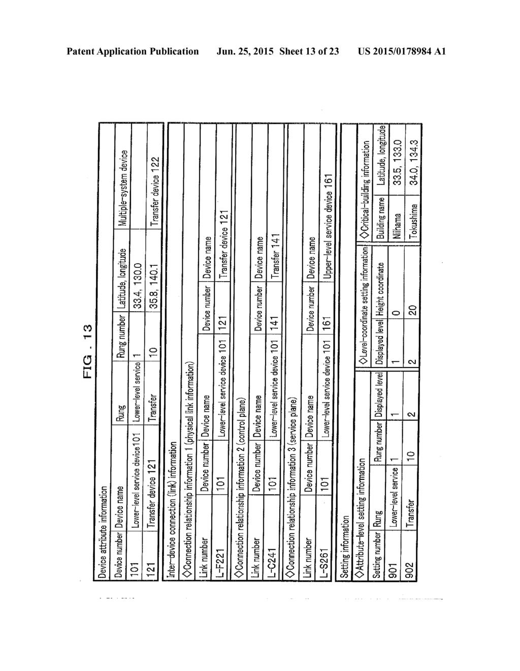
29 US 2015/O A1 Jun. 25, 2015 together with a cube as an indication that these devices are a critical building 155. This allows the viewer to more easily recognize the rung of each device Moreover, the screen display device 200 superim poses obstruction alarms issued for devices and links, on the three-dimensional display screen, as illustrated in FIG. 10. For example when an obstruction occurs to a given device in the NW and spreads to its subordinate devices and lines, the screen display device 200 displays alarm information on and around the device that is the cause of the obstruction, on the three-dimensional display screen. This allows the viewer to more readily understand where the source of obstruction is, on the display screen. Further, regarding a group of devices that form an active system/backup system group, the Screen display device 200 highlights the group by enclosing the devices with a line. For example, the screen display device 200 may enclose devices of the same group with an ellipse 154 as shown in FIGS. 9 and 10. This allows the viewer to more easily recognize devices that form an active system/ backup system group, on the screen, and thereby more readily infer to which extent a service is affected by an obstruction that has occurred to a given device For example, FIG. 10 shows an example where devices that forman active system/backup system group (the transfer devices 121, 122), as shown enclosed with the long dashed short dashed line 156, are both down. The effect of this breakdown spreads to other devices, causing the issue of a large number of alarms. Prior art display Screens merely display a large number of alarms on a display screen, which makes it difficult for the viewer to locate the source of the abnormality. The screen display device 200, on the other hand, maps those alarms around the source of the abnormality on the display screen, which allows the viewer to more easily infer where the source (center) of an abnormality is, on the display screen. Further, display of alarms on devices and links on the display screen makes it easier for the viewer to infer the extent of obstruction Further, in FIG. 10, as to display of states of alarm issue and obstruction in the NW, the screen display device 200 displays a state of alarm issue and obstruction in the NW that is at a time chosen at will by the viewer. For example, as to display of states of alarm issue and obstruction in the NW, the screen display device 200 displays a time-base bar 159 configured to receive an instruction input from the viewer for instructions a state at which time should be displayed, on the display screen so that it displays a state of alarm issue and obstruction in the NW that is at a time chosen by the time-base bar 159, on the three-dimensional display screen. This allows the viewer to see a state of alarm issue and obstruction in the NW that is at a time chosen at will by the viewer, displayed on the three-dimensional display Screen, in order to, for example, check back States of alarm issue and obstruction in the NW from the present to the past, which facilitates identi fying a device or link that is the source of the obstruction Further, as shown in FIG. 11, the screen display device 200 superimposes broken line arrows as flows 157 (flows of packets) on the three-dimensional display Screen and also, if a flow 157 is cut off at a point 158 by an obstruc tion, indicates the point 158 with a mark x'. This allows the viewer to more easily infer where the source of the abnormal ity is. Configuration Now, the configuration of the screen display device 200 is described with reference FIG. 12. As described above, the screen display device 200 generates a three-dimensional display screen that displays: the rungs of all devices in a NW and a connection relationship among the devices; information about a location of devices that forma multiple-system group; and states of various kinds of alarms and obstructions. This screen display device 200 is connected with: the devices that form the NW (for example, the transfer devices 121, 122, the control device 141, the upper-level service device 161, and the lower-level service devices , shown FIG.9), and receives, from those devices, NW information on alarms and flow rates. The screen display device 200 is also connected with an input device 400 such as a keyboard and a mouse via which the screen display device 200 receives various kinds of instruction inputs about a screen display from the viewer. Further, the screen display device 200 is connected with a display device 300 such as a liquid crystal display that per forms a screen display. On the basis of the instruction inputs from the input device 400 and information received from each device, the screen display device 200 generates a three-di mensional display screen that displays a NW State, and out puts it to the display device 300. The viewer sees the three dimensional display screen to check the NW state Functionally, the screen display device 200 is divided into a storage part 210, a processing part 220, and an input/output part 230. The storage part 210 stores various kinds of data that the processing part 220 refers to in gener ating the display screen, including: a connection relationship among the devices that form the NW; and NW information on alarms and flow rates. On the basis of instruction inputs from the input/output part 230, the processing part 220 refers to the various kinds of data stored in the storage part 210; generates a display screen; and displays it on the display device 300 via the input/output part 230. The input/output part 230 receives various kinds of instruction inputs from the input device 400 and outputs to the processing part 220. The input/output part 230 outputs the display screen generated by the processing part 220 to the display device 300, for display thereon The input/output part 230 is embodied by a commu nication interface and an input/output interface for commu nication with other devices through a NW such as Internet or a LAN (Local Area Network). The processing part 220 is embodied by execution of a program by a CPU (Central Processing Unit) of the screen display device 200, or by an exclusive circuit or the like. The storage part 210 is embodied by a storage medium such as RAM (Random Access Memory), a ROM (Read Only Memory), a HDD (Hard Disk Drive), or a flash memory. In addition, if the processing part 220 is embodied by program execution, the storage part 210 stores a program to be executed to embody the function of the processing part The storage part 210 includes a device-information storage section 211, analarm storage section 212, a flow-rate information storage section 213, and a setting storage section The device-information storage section 211 includes a device-attribute-information storage section 2111 and a device-connection-relationship storage section The device-attribute-information storage section 2111 stores device attribute information (see FIG. 13). The device attribute information is time-series information indicative of: the attribute (rung) of each device in the NW; the coordinates
 of the device on the map; and a device (a multiple-system device), if there is, to be paired with the device to forman active system/backup system pair.")
30 US 2015/O A1 Jun. 25, 2015 (the latitude and the longitude) of the device on the map; and a device (a multiple-system device), if there is, to be paired with the device to forman active system/backup system pair. In FIG. 13 as an example, the device attribute information indicates: the device number representing each device (iden tification information on each device); the device name of the device; the rung thereof; the number for the rung (the rung number); the longitude and the latitude; and the multiple system device The device-connection-relationship storage section 2112 illustrated in FIG. 12 stores time-series inter-device connection information (see FIG. 13). The inter-device con nection information is information indicative of a connection relationship among the devices in the NW. The inter-device connection information illustrated as an example in FIG. 13 indicates: a link number representing each link; a device number representing each device; a device name thereof a device number representing a device linked to the device; and a device name thereof. The inter-device connection informa tion may include: physical link information (connection rela tionship information 1); link information on the control plane (connection relationship information 2); and link information on the service plane (connection relationship information 3). as illustrated in FIG The alarm storage section 212 illustrated in FIG. 12 stores time-series alarm information to be displayed respec tively on devices and links in the NW. The alarm information is created by an alarm analysis section 223 (described below) The flow-rate-information storage section 213 stores time-series analyzed flow information. The analyzed flow information is information indicative of which devices each flow passes and is created by a flow-rate-information analysis section 224 (described below) The setting storage section 214 stores setting infor mation. The setting information is information indicative of the rung of each device; and the coordinate on the Z axis (the height) of the rung on the display screen. For example, as shown in FIG. 13, the setting information includes: attribute level setting information; and level-coordinate setting infor mation. The attribute-level setting information is indicative of the rung of each device; and the displayed level of the rung. The level-coordinate setting information is indicative of the coordinate defining the height of each displayed level. In the setting information, the closer to a terminal of the network the attribute of a device is, the smaller a value is assumed by the coordinate defining the height of the device. In addition, critical-building information illustrated in FIG. 13 is information that the processing part 220 shown in FIG. 12 refers to in displaying a cube used as a mark to show a height of the critical building 155 at an area where a device is on a rung above the lowermost rung (see FIG. 9), on the display Screen Now, the processing part 220 is described. The pro cessing part 220 includes: a device-attribute-information analysis section 221; a device-connection-relationship analy sis section 222; the alarm analysis section 223; the flow-rate information analysis section 224, a coordinate calculation section 225; and a display-information generation section 226. A viewpoint determination section 227 indicated by the broken line may be provided (see a description below) or may not be provided The device-attribute-information analysis section 221 reads, from the device-attribute-information storage sec tion 2111, device attribute information that corresponds to a time selectively input via the input/output part 230 by means of the time-base bar 159 or the like displayed on the display screen (a display time) (see FIG. 10) The device-connection-relationship analysis sec tion 222 reads inter-device connection information that cor responds to the time selectively input via the input/output part 230 by means of the time-base bar 159 and combines all together the pieces of inter-device connection information between two devices to obtain the whole NW inter-device connection structure The alarm analysis section 223 acquires alarms via an alarm reception section 231 (described below) from devices in the NW, creates alarm information in which a link and/or a device targeted for each alarm is related with a time at which the alarm has been issued, and stores the alarm information in the alarm storage section The flow-rate-information analysis section 224 receives pieces of passing-flow information via a flow-rate information reception section 232 (described below) from the devices in the NW. The flow-rate-information analysis sec tion 224 combines all together the pieces of passing-flow information received, to determine which devices each of flows has passed, and create analyzed flow information in which the devices which each flow has passed are related with times of reception of the respective pieces of passing-flow information. The flow-rate-information analysis section 224 stores the created analyzed flow information into the flow rate-information storage section 213. I0081. The coordinate calculation section 225 acquires various kinds of information that correspond to the time selectively input via the input/output part 230 by means of the time-base bar 159, whereby the coordinate calculation sec tion 225 determines the coordinates of the devices, links, flows, and of the like, on a three-dimensional display screen. The coordinate calculation section 225 is described below in greater detail. I0082 On the basis of the coordinate data output from the coordinate calculation section 225, the display-information generation section 226 generates a three-dimensional display screen in which devices, links between the devices, flows that pass the links, and alarm information on the devices and links are Superimposed and arranged, and outputs the three-dimen sional display screen to the input/output part 230. I0083. The input/output part 230 controls input/output interfaces with the display device 300, the input device 400, and each device in the NW. The input/output part 230 includes the alarm reception section 231, the flow-rate-information reception section 232, a display section 233, and an operation section 234. I0084. The alarm reception section 231 receives alarm information from devices in the NW, and outputs the received alarm information to the alarm analysis section 223. I0085. The flow-rate-information reception section 232 receives passing-flow information from devices in the NW, and outputs the received passing-flow information to the flow-rate-information analysis section 224. I0086. The display section 233 outputs the three-dimen sional display Screen generated by the display-information generation section 226 to the display device 300. I0087. The operation section234 outputs information input via the input device 400 to the coordinate calculation section Now, the coordinate calculation section 225 is described in greater detail. The coordinate calculation section
 from the device-attribute-information analysis section 221; acquires the inter-device connection information (see FIG.")
31 US 2015/O A1 Jun. 25, : acquires the device attribute information (see FIG. 13) from the device-attribute-information analysis section 221; acquires the inter-device connection information (see FIG. 13) from the device-connection-relationship analysis section 222; and acquires setting information (see FIG. 13) from the setting storage section 214. The coordinate calculation sec tion 225 acquires alarm information that is related to devices and links, from the alarm storage section 212, and acquires analyzed flow information from the flow-rate-information storage section Then, the coordinate calculation section 225 refers to the inter-device connection information, based on which the coordinate calculation section 225 determines devices and links between the devices that are at the time chosen. Further, the coordinate calculation section 225 refers to the device attribute information (see FIG. 13) and the setting information (see FIG. 13), based on which the coordinate calculation section 225 determines the coordinates, on the X andy axes on the three-dimensional display Screen, of each of the devices and links between the devices, as well as the coordinate on the Z axis that corresponds to each of the rungs to which the devices belong. Further, the coordinate calcula tion section 225 refers to the device attribute information (see FIG. 13), based on which, if it determines that there is a device that forms with a given device an active system/backup sys tem pair, the coordinate calculation section 225 places these devices on the three-dimensional display screen, together with an indication that shows that the devices form the pair. For example, as shown in an example of a display screen of FIG. 10, an ellipse 154 is drawn enclosing the devices that form the pair. Further, the coordinate calculation section 225 makes adjustments in placement to reduce crossing of links between devices and lying of one device on another on each level on the three-dimensional display Screen Moreover, the coordinate calculation section 225 refers to the alarm information, based on which, if it deter mines that there is an alarm or alarms that correspond to the display time chosen, the coordinate calculation section 225 places the alarm near a device or link targeted for the alarm, as shown in FIG. 10. Further, the coordinate calculation section 225 refers to the analyzed flow information, based on which the coordinate calculation section 225 places flows 157, that correspond to the display time chosen, on a link or links on the three-dimensional display screen that each of the flows 157 passes, as shown in FIG. 11. Then, the coordinate calculation section 225 outputs, to the display-information generation section 226, data of the three-dimensional display Screen on which the devices, links, flows, and alarm information are Superimposed and arranged (coordinate data). On the basis of this coordinate data, the display-information generation sec tion 226 generates a three-dimensional display screen as illustrated as examples in FIG. 10 and FIG. 11. Processing Steps Now, the processing steps of the screen display device 200 is described with reference to FIGS When the operation section 234 of the screen dis play device 200 of FIG. 12 receives the selective input of a time from the input device 400 via the time-base bar 159 or the like displayed on the display screen (see FIG. 10), the device-attribute-information analysis section 221 acquires, from the device-attribute-information storage section 2111, attribute information that corresponds to the time chosen (see step S1 in FIG. 14). The attribute information shows the attribute (rung) of each device and the coordinates on the X and y axes thereof The device-connection-relationship analysis sec tion 222 acquires, from the device-connection-relationship storage section 2112, inter-device connection information that corresponds to the time chosen (see FIG. 13), to deter mine the whole NW inter-device connection structure (step S2) Further, the coordinate calculation section 225 acquires, from the setting storage section 214, setting infor mation that corresponds to the time chosen (step S3). The setting information shows the coordinate on the Z axis of the rung of each device Next, the coordinate calculation section 225 refers to: the device attribute information acquired in step S1; the inter-device connection structure determined in step S2; and the setting information acquired in step S3, and thereby deter mines the coordinates, on the X and y axes on the three dimensional display screen, of each of the devices and links between the devices, as well as the coordinate on the Z axis that corresponds to each of the rungs to which the devices belong (step S4). At this time, the coordinate calculation section 225 refers to the device attribute information (see FIG. 13), based on which, if it determines that there is a device (devices) that forms together with a given device (devices) an active system/backup system pair (pairs), the coordinate cal culation section 225 places an indication (Such as an ellipse 154) enclosing the devices that form the pair, on the three dimensional display screen (see FIG. 9). Further, if it is intended that a mark Such as one for a building is placed at an area where devices are on multiple rungs, the coordinate calculation section 225 refers to building information that is included in the setting information (see FIG. 13), and places a mark such as one for a critical building 155 (cube) on the three-dimensional display screen (see FIG. 9) Further, the coordinate calculation section 225 adjusts the coordinates of devices and links to reduce crossing of links between devices and lying of one device on another on each of levels on the three-dimensional display Screen (step S5) The alarm analysis section 223 acquires alarms that have already been received by the alarm reception section 231 (step S6). Then, the alarm analysis section 223 acquires, from the device-attribute-information analysis section 221, the device attribute information (see FIG. 13), to determine devices and links targeted for the alarms. Next, the alarm analysis section 223 creates alarm information in which the devices and links targeted for the alarms are related to times of issue of the respective alarms, and outputs the created alarm information to the alarm storage section 212. This allows the alarm storage section 212 to store the latest alarm informa tion Of the alarm information stored in the alarm storage section 212, the coordinate calculation section 225 refers to alarm information that corresponds to the time chosen in step S1, as well as to the coordinates of each of devices and links as the outcome of the adjustment in step S5, and thereby determines the coordinates on the three-dimensional display screen of each alarm contained in the alarm information (step S7). (0099 Further, of the analyzed flow information stored in the flow-rate-information storage section 213, the coordinate calculation section 225 refers to one that corresponds to the

32 US 2015/O A1 Jun. 25, 2015 time chosen in step S1, and places flows onlinks that the flows pass on the three-dimensional display Screen (step S8). Then, the coordinate calculation section 225 outputs, to the display information generation section 226, data of the three-dimen sional display screen on which the devices, links, flows, and alarm information are Superimposed and arranged (coordi nate data) On the basis of this coordinate data, the display information generation section 226 generates a three-dimen sional display screen on which the devices, links, flows, and alarm information are Superimposed and arranged (step S9). and outputs the generated three-dimensional display Screen to the display device 300 (step S12) For steps S10 and S11 indicated by the broken line, these steps may be carried out (see a description below) or may not be carried out Thus the display device 300 displays a three-dimen sional display screen on which the devices placed on the multiple rungs, the devices that forman active system/backup system pair, the flows, the alarm information, and the like are shown. According to Such a display Screen, the screen viewer can more easily grasp obstruction points and the Source of obstruction in the NW, rungs, the extent of obstruction, and the like. Narrowing of Information 0103) Further, the display-information generation section 226 of the screen display device 200 of FIG. 12 may be configured to narrow information to be displayed on a three dimensional display Screen, on the basis of an instruction input that is made via the input device 400. For example, as shown in FIG. 15, the display-information generation section 226 may display only items on control and service (in FIG. 15, devices and links) and hide links between devices and transfer devices, on the screen, on the basis of the instruction input. Viewpoint Shifting 0104 Moreover, in generation of a three-dimensional dis play screen, the screen display device 200 may be configured to receive a selective input to determine a three-dimensional display screen to be viewed from which viewpoint and from which direction should be generated. In other words, the screen display device 200 may allow the discretion to be taken to choose a viewpoint and a viewpoint orientation (hereinaf ter referred to both together as a viewpoint). For example, the screen display device 200 may convert a three-dimen sional display screen shown in FIG. 16A to display a display screen viewed from viewpoint 1 (vertical viewpoint) or view point 2 (horizontal viewpoint) (see FIG.16B or FIG.16C) on the basis of a selective input made by the screen viewer In such a case, the screen display device 200 further includes a viewpoint determination section 227 illustrated in FIG. 12. After the processing in step S9 illustrated in FIG. 14, upon receipt of a selective input of a viewpoint via the opera tion section 234, the viewpoint determination section 227 determines the coordinates and orientation of a camera rela tive to the three-dimensional display screen according to the viewpoint (step S10). Then the viewpoint determination sec tion 227 outputs the coordinates of the camera to the display information generation section 226. After that, the display information generation section 226 generates a display Screen on the basis of the coordinates and the orientation of the camera; and the coordinates of the devices that are deter mined by the coordinate calculation section 225 (step S11). In other words, the coordinate calculation section 225 converts the three-dimensional display screen generated in step S9 to generate a display Screen viewed from the viewpoint chosen in step S10. Then the display-information generation section 226 outputs the generated display Screen to the display sec tion 233 (step S12) For example, if the viewpoint 1 is chosen on the three-dimensional display screen illustrated in FIG. 16A, a view from the vertical viewpoint (a plan view) as shown in FIG. 16B is yielded while if the viewpoint 2 is chosen, a view from the horizontal viewpoint (an elevational view) as shown in FIG. 16C is yielded. After that, the display-information generation section 226 adds alarm displays to the display screens from viewpoints 1 and 2 to generate display screens as illustrated in FIGS. 17A and 17B Further, on the basis of an instruction input made by the viewer, the display-information generation section 226 may generate a display Screen on which information is nar rowed to only a part of devices and links in the NW. For example, the display-information generation section 226 may generate a display Screen the information on which is nar rowed to the devices and links on the service plane as shown in FIG. 17C. This allows the screen viewer to more readily check a state of only a part of devices and links in the NW so that the viewer can more easily infer the source of obstruction and the extent of obstruction, on the display Screen. How to Display Alarms Moreover, the display-information generation sec tion 226 may be configured to generate a display Screen with various display colors, sizes, etc., of alarms according to the kind of the alarm on the display Screen so that the Screen viewer can more easily identify critical obstruction points. For example, the display-information generation section 226 may be configured to enable discrimination between alarms with a high criticality and alarms with a low criticality by the alarm icon size as shown in FIG. 18. Moreover, the display information generation section 226 may be configured to flash light to indicate alarms that are issued within a most recent predetermined period of time. This allows the screen viewer to more easily recognize changes in a NW State, on the display screen. Playback Display 0109 Further, the screen display device 200 may be con figured to display sequentially NW obstruction state changes from a time in the past chosen by the screen viewer through the present time. In other words, the screen display device 200 may be configured to display the playback of the NW states from the past through the present For example in an example of an obstruction illus trated in FIGS. 19 A-19C, assume that the obstruction occurs to the transfer device 121 in the NW, then spreads to the transfer device 122, which causes the issue of alarms for the links in the whole NW. In this case the display-information generation section 226 of FIG. 12 generates three-dimen sional display screens representing the NW states from a time in the past chosen by the viewer via the time-base bar 159 displayed on the display screen through the present. Then the display-information generation section 226 displays these three-dimensional display screens sequentially via the dis

33 US 2015/O A1 Jun. 25, 2015 play section 233, on the display device 300. For example, the time-base bar 159 is shifted to the left on a screen which shows the current state illustrated in FIG. 19C to choose a time, according to which the display-information generation section 226 displays a screen which shows a state in the past illustrated in FIG. 19A, followed by displaying a screen which shows the next state in the past illustrated in FIG. 19C, then returning to the screen which shows the current state illustrated in FIG. 19C. This allows the viewer to more easily understand which device in the NW is the cause of the obstruction issuing the first alarm, as well as states of alarm issue and obstruction, by checking in time sequence on the display Screen Note that although in the above-described embodi ment, a mark such as one for critical building 155 is shown to facilitate understanding of the rungs of the individual devices on the three-dimensional display Screen, the invention is not limited to this configuration. For example, the screen display device 200 may be configured to display the Z axis, out of the X, y, and Z axes, or display lines etc., that indicate the rungs (levels), on the three-dimensional display screen. DESCRIPTION OF REFERENCE NUMERALS screen display device storage part 0114) 211 device-information storage section alarm storage section flow-rate-information storage section setting storage section processing part device-attribute-information analysis section 0120) 222 device-connection-relationship analysis sec tion alarm analysis section flow-rate-information analysis section coordinate calculation section display-information generation section viewpoint determination section input/output part alarm reception section flow-rate-information reception section display section operation section display device (0132) 400 input device device-attribute-information storage section 0134) 2112 device-connection-relationship storage sec tion 1. A screen display device configured to generate a screen that shows a state of a network, comprising: a storage part configured to store: (1) device attribute information indicative of: information indicative of which one of attributes is an attribute of each of a plurality of devices that form the network, the attributes being: a terminal device of the network; a server device; a transfer device; and a control device, the server device being configured to transmit to and receive from the terminal device various kinds of data, the transfer device being configured to transfer the data between the server device and the terminal device, and the control device being configured to control the transfer device and the terminal device; coordinates of the device on a map; and, if the device as a first device and a second device which is another one of the plurality of devices form a pair of an active system/backup system, the second device, (2) inter-device connection information indicative of a con nection relationship among the plurality of devices, (3) setting information indicative of a rung corresponding to each attribute; and a coordinate defining a height of a device belonging to each rung relative to a three-dimensional display SCreen, (4) analyzed flow information indicative of devices traversed by each of a plurality of flows of the network, and (5) alarm information indicative of alarms to be displayed respectively on devices of the network and links between the devices, each item of the information (1) (5) being stored together with its time information; an input/output part config ured to receive a selective input of a display time that gives instructions that a network State at which time should be displayed and to output to the display device a three-dimensional display screen displaying the net work State, the three-dimensional display screen being generated by a processing part; and the processing part configured to generate the three-dimen sional display screen, the processing part: referring to the inter-device connection information to determine a connection relationship among the plurality of devices that is at the selectively inputted display time, referring to the device attribute information and the setting information to determine coordinates of each of the plu rality of devices relative to an Xy plane and a coordinate thereof relative to a Z axis of the three-dimensional dis play Screen that are at the selectively inputted display time, and placing each of the plurality of devices at the determined coordinates of the three-dimensional dis play Screen, referring to the device attribute information and, if at the selectively inputted display time, there is the second device paired with the device, placing the pair on the three-dimensional display screen together with an indi cation showing that the devices are a pair, referring to the alarm information and, if there are devices and links targeted for alarms at the selectively inputted display time, placing the alarms near the devices and links for which the alarms are issued, referring to the analyzed flow information to determine flows that are at the selectively input display time, and placing each flow on a link of the three-dimensional display screen that is traversed by the flow, and generating a three-dimensional display Screen on which there are Superimposed and placed: the plurality of devices; the plurality of links between the plurality of devices; the flows that traverse the links; and the alarm information on the devices and links. 2. The screen display device according to claim 1, wherein the coordinate defining a height of a device belonging to each rung in the setting information is set so that the closer to a terminal of the network the attribute of the device is, the Smaller a value is assumed by the coordinate defining the height of the device. 3. The screen display device according to claim 1, wherein the processing part generates time-series three-dimensional display Screens spanning from the selectively input display

34 US 2015/O A1 Jun. 25, 2015 time to a predetermined time and displays sequentially the generated three-dimensional display Screens via the input/ output part. 4. The screen display device according to claim 1, wherein the processing part generates a three-dimensional display screen in which adjustments are made to reduce crossing of the devices, links, flows, and alarm information placed thereon. 5. The screen display device according to claim 1, wherein when the processing part receives via the input/output part a selective input of a viewpoint and of a direction from which to view the three-dimensional display screen, the processing part generates a three-dimensional display Screen viewed from the selected viewpoint and direction. 6. A system comprising: the screen display device as cited in claim 1; and a plurality of devices that form a network configured to transmit to and receive from the screen display device an information source of the alarm information and of the analyzed flow information. 7. (canceled) 8. A system comprising: the screen display device as cited in claim 2; and a plurality of devices that form a network configured to transmit to and receive from the screen display device an information source of the alarm information and of the analyzed flow information 9. A system comprising: the screen display device as cited in claim 3; and a plurality of devices that form a network configured to transmit to and receive from the screen display device an information source of the alarm information and of the analyzed flow information. 10. A system comprising: the screen display device as cited in claim 4; and a plurality of devices that form a network configured to transmit to and receive from the screen display device an information source of the alarm information and of the analyzed flow information. 11. A system comprising: the screen display device as cited in claim 5; and a plurality of devices that form a network configured to transmit to and receive from the screen display device an information source of the alarm information and of the analyzed flow information. 12. A screen generation method using a screen display device configured to generate a screen that shows a state of a network, the screen display device comprising: a storage part configured to store: (1) device attribute information indicative of: information indicative of which one of attributes is an attribute of each of a plurality of devices that form the network, the attributes being: a terminal device of the network; a server device; a transfer device; and a control device, the server device being configured to transmit to and receive from the terminal device various kinds of data, the transfer device being configured to transfer the data between the server device and the terminal device, and the control device being configured to control the transfer device and the terminal device; coordinates of the device on a map; and, if the device as a first device and a second device which is another one of the plurality of devices form a pair of an active system/backup system, the second device, (2) inter-device connection information indicative of a con nection relationship among the plurality of devices, (3) setting information indicative of a rung corresponding to each attribute; and a coordinate defining a height of a device belonging to each rung relative to a three-dimensional display SCreen, (4) analyzed flow information indicative of devices traversed by each of a plurality of flows of the network, and (5) alarm information indicative of alarms issued to be dis played respectively on devices of the network and for links between devices, each item of the information (1) (5) being stored together with its time information; an input/output part configured to receive a selective input of a display time that gives instructions that a network state at which time should be displayed and to output to the display device a three-dimensional display Screen displaying the network State, the three-dimensional dis play Screen being generated by a processing part; and the processing part configured to generate the three-dimen sional display screen, the processing part performing: a step of referring to the inter-device connection informa tion to determine a connection relationship among the plurality of devices that is at the selectively inputted display time, a step of referring to the device attribute information and the setting information to determine coordinates of each of the plurality of devices relative to an xy plane and a coordinate thereof relative to a Z axis of the three-dimen sional display Screen that are at the selectively inputted display time, and placing each of the plurality of devices at the determined coordinates of the three-dimensional display screen, a step of referring to the device attribute information and, if at the selectively inputted display time, there is a device to be paired with the device, placing the pair on the three-dimensional display screen together with an indi cation showing that the devices are a pair, a step of referring to the alarm information and, if there are devices and links targeted for alarms at the selectively inputted display time, placing the alarms near the devices and links for which the alarms are issued, a step of referring to the analyzed flow information to determine flows that are at the selectively input display time, and placing each flow on a link of the three-dimen sional display screen that is traversed by the flow, and a step of generating a three-dimensional display Screen on which there are Superimposed and placed: the plurality of devices; the plurality of links between the plurality of devices; the flows that traverse the links; and the alarm information on the devices and links. k k k k k
(12) Patent Application Publication (10) Pub. No.: US 2006/ A1. (51) Int. Cl. SELECT A PLURALITY OF TIME SHIFT CHANNELS
 Patent Application Publication (10) Pub. No.: US 2006/ A1. (51) Int. Cl. SELECT A PLURALITY OF TIME SHIFT CHANNELS") (19) United States (12) Patent Application Publication (10) Pub. No.: Lee US 2006OO15914A1 (43) Pub. Date: Jan. 19, 2006 (54) RECORDING METHOD AND APPARATUS CAPABLE OF TIME SHIFTING INA PLURALITY OF CHANNELS
(19) United States (12) Patent Application Publication (10) Pub. No.: Lee US 2006OO15914A1 (43) Pub. Date: Jan. 19, 2006 (54) RECORDING METHOD AND APPARATUS CAPABLE OF TIME SHIFTING INA PLURALITY OF CHANNELS
(12) Patent Application Publication (10) Pub. No.: US 2015/ A1
 Patent Application Publication (10) Pub. No.: US 2015/ A1") (19) United States (12) Patent Application Publication (10) Pub. No.: US 2015/0116196A1 Liu et al. US 2015O11 6 196A1 (43) Pub. Date: Apr. 30, 2015 (54) (71) (72) (73) (21) (22) (86) (30) LED DISPLAY MODULE,
(19) United States (12) Patent Application Publication (10) Pub. No.: US 2015/0116196A1 Liu et al. US 2015O11 6 196A1 (43) Pub. Date: Apr. 30, 2015 (54) (71) (72) (73) (21) (22) (86) (30) LED DISPLAY MODULE,
(12) Patent Application Publication (10) Pub. No.: US 2005/ A1
 Patent Application Publication (10) Pub. No.: US 2005/ A1") (19) United States US 20050008347A1 (12) Patent Application Publication (10) Pub. No.: US 2005/0008347 A1 Jung et al. (43) Pub. Date: Jan. 13, 2005 (54) METHOD OF PROCESSING SUBTITLE STREAM, REPRODUCING
(19) United States US 20050008347A1 (12) Patent Application Publication (10) Pub. No.: US 2005/0008347 A1 Jung et al. (43) Pub. Date: Jan. 13, 2005 (54) METHOD OF PROCESSING SUBTITLE STREAM, REPRODUCING
(12) Patent Application Publication (10) Pub. No.: US 2014/ A1
 Patent Application Publication (10) Pub. No.: US 2014/ A1") (19) United States US 20140176798A1 (12) Patent Application Publication (10) Pub. No.: US 2014/0176798 A1 TANAKA et al. (43) Pub. Date: Jun. 26, 2014 (54) BROADCAST IMAGE OUTPUT DEVICE, BROADCAST IMAGE
(19) United States US 20140176798A1 (12) Patent Application Publication (10) Pub. No.: US 2014/0176798 A1 TANAKA et al. (43) Pub. Date: Jun. 26, 2014 (54) BROADCAST IMAGE OUTPUT DEVICE, BROADCAST IMAGE
(12) Patent Application Publication (10) Pub. No.: US 2011/ A1
 Patent Application Publication (10) Pub. No.: US 2011/ A1") (19) United States US 2011 0320948A1 (12) Patent Application Publication (10) Pub. No.: US 2011/0320948 A1 CHO (43) Pub. Date: Dec. 29, 2011 (54) DISPLAY APPARATUS AND USER Publication Classification INTERFACE
(19) United States US 2011 0320948A1 (12) Patent Application Publication (10) Pub. No.: US 2011/0320948 A1 CHO (43) Pub. Date: Dec. 29, 2011 (54) DISPLAY APPARATUS AND USER Publication Classification INTERFACE
(12) Patent Application Publication (10) Pub. No.: US 2001/ A1
 Patent Application Publication (10) Pub. No.: US 2001/ A1") (19) United States US 2001.0056361A1 (12) Patent Application Publication (10) Pub. No.: US 2001/0056361A1 Sendouda (43) Pub. Date: Dec. 27, 2001 (54) CAR RENTAL SYSTEM (76) Inventor: Mitsuru Sendouda,
(19) United States US 2001.0056361A1 (12) Patent Application Publication (10) Pub. No.: US 2001/0056361A1 Sendouda (43) Pub. Date: Dec. 27, 2001 (54) CAR RENTAL SYSTEM (76) Inventor: Mitsuru Sendouda,
(12) Patent Application Publication (10) Pub. No.: US 2015/ A1
 Patent Application Publication (10) Pub. No.: US 2015/ A1") US 20150358554A1 (19) United States (12) Patent Application Publication (10) Pub. No.: US 2015/0358554 A1 Cheong et al. (43) Pub. Date: Dec. 10, 2015 (54) PROACTIVELY SELECTINGA Publication Classification
US 20150358554A1 (19) United States (12) Patent Application Publication (10) Pub. No.: US 2015/0358554 A1 Cheong et al. (43) Pub. Date: Dec. 10, 2015 (54) PROACTIVELY SELECTINGA Publication Classification
(12) Patent Application Publication (10) Pub. No.: US 2016/ A1
 Patent Application Publication (10) Pub. No.: US 2016/ A1") (19) United States US 201600274O2A1 (12) Patent Application Publication (10) Pub. No.: US 2016/00274.02 A1 YANAZUME et al. (43) Pub. Date: Jan. 28, 2016 (54) WIRELESS COMMUNICATIONS SYSTEM, AND DISPLAY
(19) United States US 201600274O2A1 (12) Patent Application Publication (10) Pub. No.: US 2016/00274.02 A1 YANAZUME et al. (43) Pub. Date: Jan. 28, 2016 (54) WIRELESS COMMUNICATIONS SYSTEM, AND DISPLAY
(12) Patent Application Publication (10) Pub. No.: US 2011/ A1
 Patent Application Publication (10) Pub. No.: US 2011/ A1") US 2011 0016428A1 (19) United States (12) Patent Application Publication (10) Pub. No.: US 2011/0016428A1 Lupton, III et al. (43) Pub. Date: (54) NESTED SCROLLING SYSTEM Publication Classification O O
US 2011 0016428A1 (19) United States (12) Patent Application Publication (10) Pub. No.: US 2011/0016428A1 Lupton, III et al. (43) Pub. Date: (54) NESTED SCROLLING SYSTEM Publication Classification O O
(12) Patent Application Publication (10) Pub. No.: US 2010/ A1
 Patent Application Publication (10) Pub. No.: US 2010/ A1") US 2010.0097.523A1. (19) United States (12) Patent Application Publication (10) Pub. No.: US 2010/0097523 A1 SHIN (43) Pub. Date: Apr. 22, 2010 (54) DISPLAY APPARATUS AND CONTROL (30) Foreign Application
US 2010.0097.523A1. (19) United States (12) Patent Application Publication (10) Pub. No.: US 2010/0097523 A1 SHIN (43) Pub. Date: Apr. 22, 2010 (54) DISPLAY APPARATUS AND CONTROL (30) Foreign Application
(12) Patent Application Publication (10) Pub. No.: US 2006/ A1. (51) Int. Cl.
 Patent Application Publication (10) Pub. No.: US 2006/ A1. (51) Int. Cl.") (19) United States US 20060034.186A1 (12) Patent Application Publication (10) Pub. No.: US 2006/0034186 A1 Kim et al. (43) Pub. Date: Feb. 16, 2006 (54) FRAME TRANSMISSION METHOD IN WIRELESS ENVIRONMENT
(19) United States US 20060034.186A1 (12) Patent Application Publication (10) Pub. No.: US 2006/0034186 A1 Kim et al. (43) Pub. Date: Feb. 16, 2006 (54) FRAME TRANSMISSION METHOD IN WIRELESS ENVIRONMENT
III... III: III. III.
 (19) United States US 2015 0084.912A1 (12) Patent Application Publication (10) Pub. No.: US 2015/0084912 A1 SEO et al. (43) Pub. Date: Mar. 26, 2015 9 (54) DISPLAY DEVICE WITH INTEGRATED (52) U.S. Cl.
(12) United States Patent
 United States Patent") (12) United States Patent Imai et al. USOO6507611B1 (10) Patent No.: (45) Date of Patent: Jan. 14, 2003 (54) TRANSMITTING APPARATUS AND METHOD, RECEIVING APPARATUS AND METHOD, AND PROVIDING MEDIUM (75)
(12) United States Patent Imai et al. USOO6507611B1 (10) Patent No.: (45) Date of Patent: Jan. 14, 2003 (54) TRANSMITTING APPARATUS AND METHOD, RECEIVING APPARATUS AND METHOD, AND PROVIDING MEDIUM (75)
(12) Patent Application Publication (10) Pub. No.: US 2010/ A1. (51) Int. Cl.
 Patent Application Publication (10) Pub. No.: US 2010/ A1. (51) Int. Cl.") (19) United States US 2010.0034442A1 (12) Patent Application Publication (10) Pub. No.: US 2010/0034442 A1 MINAKUCH et al. (43) Pub. Date: (54) REPORT GENERATION SUPPORT APPARATUS, REPORT GENERATION SUPPORT
(19) United States US 2010.0034442A1 (12) Patent Application Publication (10) Pub. No.: US 2010/0034442 A1 MINAKUCH et al. (43) Pub. Date: (54) REPORT GENERATION SUPPORT APPARATUS, REPORT GENERATION SUPPORT
(12) Patent Application Publication (10) Pub. No.: US 2010/ A1
 Patent Application Publication (10) Pub. No.: US 2010/ A1") (19) United States US 2010.0020005A1 (12) Patent Application Publication (10) Pub. No.: US 2010/0020005 A1 Jung et al. (43) Pub. Date: Jan. 28, 2010 (54) APPARATUS AND METHOD FOR COMPENSATING BRIGHTNESS
(19) United States US 2010.0020005A1 (12) Patent Application Publication (10) Pub. No.: US 2010/0020005 A1 Jung et al. (43) Pub. Date: Jan. 28, 2010 (54) APPARATUS AND METHOD FOR COMPENSATING BRIGHTNESS
(12) Patent Application Publication (10) Pub. No.: US 2016/ A1
 Patent Application Publication (10) Pub. No.: US 2016/ A1") (19) United States (12) Patent Application Publication (10) Pub. No.: US 2016/0080549 A1 YUAN et al. US 2016008.0549A1 (43) Pub. Date: Mar. 17, 2016 (54) (71) (72) (73) MULT-SCREEN CONTROL METHOD AND DEVICE
(19) United States (12) Patent Application Publication (10) Pub. No.: US 2016/0080549 A1 YUAN et al. US 2016008.0549A1 (43) Pub. Date: Mar. 17, 2016 (54) (71) (72) (73) MULT-SCREEN CONTROL METHOD AND DEVICE
(12) Patent Application Publication (10) Pub. No.: US 2005/ A1
 Patent Application Publication (10) Pub. No.: US 2005/ A1") (19) United States US 2005O105810A1 (12) Patent Application Publication (10) Pub. No.: US 2005/0105810 A1 Kim (43) Pub. Date: May 19, 2005 (54) METHOD AND DEVICE FOR CONDENSED IMAGE RECORDING AND REPRODUCTION
(19) United States US 2005O105810A1 (12) Patent Application Publication (10) Pub. No.: US 2005/0105810 A1 Kim (43) Pub. Date: May 19, 2005 (54) METHOD AND DEVICE FOR CONDENSED IMAGE RECORDING AND REPRODUCTION
(12) United States Patent (10) Patent No.: US 6,424,795 B1
 United States Patent (10) Patent No.: US 6,424,795 B1") USOO6424795B1 (12) United States Patent (10) Patent No.: Takahashi et al. () Date of Patent: Jul. 23, 2002 (54) METHOD AND APPARATUS FOR 5,444,482 A 8/1995 Misawa et al.... 386/120 RECORDING AND REPRODUCING
USOO6424795B1 (12) United States Patent (10) Patent No.: Takahashi et al. () Date of Patent: Jul. 23, 2002 (54) METHOD AND APPARATUS FOR 5,444,482 A 8/1995 Misawa et al.... 386/120 RECORDING AND REPRODUCING
(12) Patent Application Publication (10) Pub. No.: US 2008/ A1
 Patent Application Publication (10) Pub. No.: US 2008/ A1") (19) United States US 2008O144051A1 (12) Patent Application Publication (10) Pub. No.: US 2008/0144051A1 Voltz et al. (43) Pub. Date: (54) DISPLAY DEVICE OUTPUT ADJUSTMENT SYSTEMAND METHOD (76) Inventors:
(19) United States US 2008O144051A1 (12) Patent Application Publication (10) Pub. No.: US 2008/0144051A1 Voltz et al. (43) Pub. Date: (54) DISPLAY DEVICE OUTPUT ADJUSTMENT SYSTEMAND METHOD (76) Inventors:
2) }25 2 O TUNE IF. CHANNEL, TS i AUDIO
 }25 2 O TUNE IF. CHANNEL, TS i AUDIO") US 20050160453A1 (19) United States (12) Patent Application Publication (10) Pub. N0.: US 2005/0160453 A1 Kim (43) Pub. Date: (54) APPARATUS TO CHANGE A CHANNEL (52) US. Cl...... 725/39; 725/38; 725/120;
US 20050160453A1 (19) United States (12) Patent Application Publication (10) Pub. N0.: US 2005/0160453 A1 Kim (43) Pub. Date: (54) APPARATUS TO CHANGE A CHANNEL (52) US. Cl...... 725/39; 725/38; 725/120;
(12) Patent Application Publication (10) Pub. No.: US 2004/ A1
 Patent Application Publication (10) Pub. No.: US 2004/ A1") (19) United States US 004063758A1 (1) Patent Application Publication (10) Pub. No.: US 004/063758A1 Lee et al. (43) Pub. Date: Dec. 30, 004 (54) LINE ON GLASS TYPE LIQUID CRYSTAL (30) Foreign Application
(19) United States US 004063758A1 (1) Patent Application Publication (10) Pub. No.: US 004/063758A1 Lee et al. (43) Pub. Date: Dec. 30, 004 (54) LINE ON GLASS TYPE LIQUID CRYSTAL (30) Foreign Application
(12) Patent Application Publication (10) Pub. No.: US 2010/ A1
 Patent Application Publication (10) Pub. No.: US 2010/ A1") (19) United States US 2010.0245680A1 (12) Patent Application Publication (10) Pub. No.: US 2010/0245680 A1 TSUKADA et al. (43) Pub. Date: Sep. 30, 2010 (54) TELEVISION OPERATION METHOD (30) Foreign Application
(19) United States US 2010.0245680A1 (12) Patent Application Publication (10) Pub. No.: US 2010/0245680 A1 TSUKADA et al. (43) Pub. Date: Sep. 30, 2010 (54) TELEVISION OPERATION METHOD (30) Foreign Application
(12) Patent Application Publication (10) Pub. No.: US 2013/ A1
 Patent Application Publication (10) Pub. No.: US 2013/ A1") (19) United States US 2013 0100156A1 (12) Patent Application Publication (10) Pub. No.: US 2013/0100156A1 JANG et al. (43) Pub. Date: Apr. 25, 2013 (54) PORTABLE TERMINAL CAPABLE OF (30) Foreign Application
(19) United States US 2013 0100156A1 (12) Patent Application Publication (10) Pub. No.: US 2013/0100156A1 JANG et al. (43) Pub. Date: Apr. 25, 2013 (54) PORTABLE TERMINAL CAPABLE OF (30) Foreign Application
(12) Patent Application Publication (10) Pub. No.: US 2014/ A1
 Patent Application Publication (10) Pub. No.: US 2014/ A1") (19) United States US 2014O1 O1585A1 (12) Patent Application Publication (10) Pub. No.: US 2014/0101585 A1 YOO et al. (43) Pub. Date: Apr. 10, 2014 (54) IMAGE PROCESSINGAPPARATUS AND (30) Foreign Application
(19) United States US 2014O1 O1585A1 (12) Patent Application Publication (10) Pub. No.: US 2014/0101585 A1 YOO et al. (43) Pub. Date: Apr. 10, 2014 (54) IMAGE PROCESSINGAPPARATUS AND (30) Foreign Application
(12) Patent Application Publication (10) Pub. No.: US 2009/ A1. (51) Int. Cl. CLK CK CLK2 SOUrce driver. Y Y SUs DAL h-dal -DAL
 Patent Application Publication (10) Pub. No.: US 2009/ A1. (51) Int. Cl. CLK CK CLK2 SOUrce driver. Y Y SUs DAL h-dal -DAL") (19) United States (12) Patent Application Publication (10) Pub. No.: US 2009/0079669 A1 Huang et al. US 20090079669A1 (43) Pub. Date: Mar. 26, 2009 (54) FLAT PANEL DISPLAY (75) Inventors: Tzu-Chien Huang,
(19) United States (12) Patent Application Publication (10) Pub. No.: US 2009/0079669 A1 Huang et al. US 20090079669A1 (43) Pub. Date: Mar. 26, 2009 (54) FLAT PANEL DISPLAY (75) Inventors: Tzu-Chien Huang,
(12) United States Patent
 United States Patent") (12) United States Patent USOO71 6 1 494 B2 (10) Patent No.: US 7,161,494 B2 AkuZaWa (45) Date of Patent: Jan. 9, 2007 (54) VENDING MACHINE 5,831,862 A * 11/1998 Hetrick et al.... TOOf 232 75 5,959,869
(12) United States Patent USOO71 6 1 494 B2 (10) Patent No.: US 7,161,494 B2 AkuZaWa (45) Date of Patent: Jan. 9, 2007 (54) VENDING MACHINE 5,831,862 A * 11/1998 Hetrick et al.... TOOf 232 75 5,959,869
(12) United States Patent
 United States Patent") (12) United States Patent USOO9678590B2 (10) Patent No.: US 9,678,590 B2 Nakayama (45) Date of Patent: Jun. 13, 2017 (54) PORTABLE ELECTRONIC DEVICE (56) References Cited (75) Inventor: Shusuke Nakayama,
(12) United States Patent USOO9678590B2 (10) Patent No.: US 9,678,590 B2 Nakayama (45) Date of Patent: Jun. 13, 2017 (54) PORTABLE ELECTRONIC DEVICE (56) References Cited (75) Inventor: Shusuke Nakayama,
(12) Patent Application Publication (10) Pub. No.: US 2007/ A1
 Patent Application Publication (10) Pub. No.: US 2007/ A1") (19) United States US 20070226600A1 (12) Patent Application Publication (10) Pub. No.: US 2007/0226600 A1 gawa (43) Pub. Date: Sep. 27, 2007 (54) SEMICNDUCTR INTEGRATED CIRCUIT (30) Foreign Application
(19) United States US 20070226600A1 (12) Patent Application Publication (10) Pub. No.: US 2007/0226600 A1 gawa (43) Pub. Date: Sep. 27, 2007 (54) SEMICNDUCTR INTEGRATED CIRCUIT (30) Foreign Application
(12) Patent Application Publication (10) Pub. No.: US 2015/ A1
 Patent Application Publication (10) Pub. No.: US 2015/ A1") (19) United States US 2015.0054800A1 (12) Patent Application Publication (10) Pub. No.: US 2015/0054800 A1 KM et al. (43) Pub. Date: Feb. 26, 2015 (54) METHOD AND APPARATUS FOR DRIVING (30) Foreign Application
(19) United States US 2015.0054800A1 (12) Patent Application Publication (10) Pub. No.: US 2015/0054800 A1 KM et al. (43) Pub. Date: Feb. 26, 2015 (54) METHOD AND APPARATUS FOR DRIVING (30) Foreign Application
(12) Patent Application Publication (10) Pub. No.: US 2011/ A1
 Patent Application Publication (10) Pub. No.: US 2011/ A1") (19) United States (12) Patent Application Publication (10) Pub. No.: US 2011/0084992 A1 Ishizuka US 20110084992A1 (43) Pub. Date: Apr. 14, 2011 (54) (75) (73) (21) (22) (86) ACTIVE MATRIX DISPLAY APPARATUS
(19) United States (12) Patent Application Publication (10) Pub. No.: US 2011/0084992 A1 Ishizuka US 20110084992A1 (43) Pub. Date: Apr. 14, 2011 (54) (75) (73) (21) (22) (86) ACTIVE MATRIX DISPLAY APPARATUS
(12) United States Patent (10) Patent No.: US 6,275,266 B1
 United States Patent (10) Patent No.: US 6,275,266 B1") USOO6275266B1 (12) United States Patent (10) Patent No.: Morris et al. (45) Date of Patent: *Aug. 14, 2001 (54) APPARATUS AND METHOD FOR 5,8,208 9/1998 Samela... 348/446 AUTOMATICALLY DETECTING AND 5,841,418
USOO6275266B1 (12) United States Patent (10) Patent No.: Morris et al. (45) Date of Patent: *Aug. 14, 2001 (54) APPARATUS AND METHOD FOR 5,8,208 9/1998 Samela... 348/446 AUTOMATICALLY DETECTING AND 5,841,418
(12) Patent Application Publication (10) Pub. No.: US 2010/ A1
 Patent Application Publication (10) Pub. No.: US 2010/ A1") US 2010O283828A1 (19) United States (12) Patent Application Publication (10) Pub. No.: US 2010/0283828A1 Lee et al. (43) Pub. Date: Nov. 11, 2010 (54) MULTI-VIEW 3D VIDEO CONFERENCE (30) Foreign Application
US 2010O283828A1 (19) United States (12) Patent Application Publication (10) Pub. No.: US 2010/0283828A1 Lee et al. (43) Pub. Date: Nov. 11, 2010 (54) MULTI-VIEW 3D VIDEO CONFERENCE (30) Foreign Application
Dm 200. (12) Patent Application Publication (10) Pub. No.: US 2007/ A1. (19) United States. User. (43) Pub. Date: Oct. 18, 2007.
 Patent Application Publication (10) Pub. No.: US 2007/ A1. (19) United States. User. (43) Pub. Date: Oct. 18, 2007.") (19) United States (12) Patent Application Publication (10) Pub. No.: US 2007/0242068 A1 Han et al. US 20070242068A1 (43) Pub. Date: (54) 2D/3D IMAGE DISPLAY DEVICE, ELECTRONIC IMAGING DISPLAY DEVICE,
(19) United States (12) Patent Application Publication (10) Pub. No.: US 2007/0242068 A1 Han et al. US 20070242068A1 (43) Pub. Date: (54) 2D/3D IMAGE DISPLAY DEVICE, ELECTRONIC IMAGING DISPLAY DEVICE,
(12) United States Patent Nagashima et al.
 United States Patent Nagashima et al.") (12) United States Patent Nagashima et al. US006953887B2 (10) Patent N0.: (45) Date of Patent: Oct. 11, 2005 (54) SESSION APPARATUS, CONTROL METHOD THEREFOR, AND PROGRAM FOR IMPLEMENTING THE CONTROL METHOD
(12) United States Patent Nagashima et al. US006953887B2 (10) Patent N0.: (45) Date of Patent: Oct. 11, 2005 (54) SESSION APPARATUS, CONTROL METHOD THEREFOR, AND PROGRAM FOR IMPLEMENTING THE CONTROL METHOD
(12) United States Patent
 United States Patent") (12) United States Patent US0070901.37B1 (10) Patent No.: US 7,090,137 B1 Bennett (45) Date of Patent: Aug. 15, 2006 (54) DATA COLLECTION DEVICE HAVING (56) References Cited VISUAL DISPLAY OF FEEDBACK
(12) United States Patent US0070901.37B1 (10) Patent No.: US 7,090,137 B1 Bennett (45) Date of Patent: Aug. 15, 2006 (54) DATA COLLECTION DEVICE HAVING (56) References Cited VISUAL DISPLAY OF FEEDBACK
) 342. (12) Patent Application Publication (10) Pub. No.: US 2016/ A1. (19) United States MAGE ANALYZER TMING CONTROLLER SYNC CONTROLLER CTL
 342. (12) Patent Application Publication (10) Pub. No.: US 2016/ A1. (19) United States MAGE ANALYZER TMING CONTROLLER SYNC CONTROLLER CTL") (19) United States US 20160063939A1 (12) Patent Application Publication (10) Pub. No.: US 2016/0063939 A1 LEE et al. (43) Pub. Date: Mar. 3, 2016 (54) DISPLAY PANEL CONTROLLER AND DISPLAY DEVICE INCLUDING
(19) United States US 20160063939A1 (12) Patent Application Publication (10) Pub. No.: US 2016/0063939 A1 LEE et al. (43) Pub. Date: Mar. 3, 2016 (54) DISPLAY PANEL CONTROLLER AND DISPLAY DEVICE INCLUDING
(12) Patent Application Publication (10) Pub. No.: US 2007/ A1
 Patent Application Publication (10) Pub. No.: US 2007/ A1") (19) United States (12) Patent Application Publication (10) Pub. No.: US 2007/0230902 A1 Shen et al. US 20070230902A1 (43) Pub. Date: Oct. 4, 2007 (54) (75) (73) (21) (22) (60) DYNAMIC DISASTER RECOVERY
(19) United States (12) Patent Application Publication (10) Pub. No.: US 2007/0230902 A1 Shen et al. US 20070230902A1 (43) Pub. Date: Oct. 4, 2007 (54) (75) (73) (21) (22) (60) DYNAMIC DISASTER RECOVERY
(12) Patent Application Publication (10) Pub. No.: US 2004/ A1
 Patent Application Publication (10) Pub. No.: US 2004/ A1") (19) United States US 2004O184531A1 (12) Patent Application Publication (10) Pub. No.: US 2004/0184531A1 Lim et al. (43) Pub. Date: Sep. 23, 2004 (54) DUAL VIDEO COMPRESSION METHOD Publication Classification
(19) United States US 2004O184531A1 (12) Patent Application Publication (10) Pub. No.: US 2004/0184531A1 Lim et al. (43) Pub. Date: Sep. 23, 2004 (54) DUAL VIDEO COMPRESSION METHOD Publication Classification
(12) Patent Application Publication (10) Pub. No.: US 2013/ A1
 Patent Application Publication (10) Pub. No.: US 2013/ A1") US 2013 0127749A1 (19) United States (12) Patent Application Publication (10) Pub. No.: US 2013/0127749 A1 YAMAMOTO et al. (43) Pub. Date: May 23, 2013 (54) ELECTRONIC DEVICE AND TOUCH Publication Classification
US 2013 0127749A1 (19) United States (12) Patent Application Publication (10) Pub. No.: US 2013/0127749 A1 YAMAMOTO et al. (43) Pub. Date: May 23, 2013 (54) ELECTRONIC DEVICE AND TOUCH Publication Classification
(12) Patent Application Publication (10) Pub. No.: US 2017/ A1. (51) Int. Cl. (52) U.S. Cl. M M 110 / <E
 Patent Application Publication (10) Pub. No.: US 2017/ A1. (51) Int. Cl. (52) U.S. Cl. M M 110 / <E") (19) United States US 20170082735A1 (12) Patent Application Publication (10) Pub. No.: US 2017/0082735 A1 SLOBODYANYUK et al. (43) Pub. Date: ar. 23, 2017 (54) (71) (72) (21) (22) LIGHT DETECTION AND RANGING
(19) United States US 20170082735A1 (12) Patent Application Publication (10) Pub. No.: US 2017/0082735 A1 SLOBODYANYUK et al. (43) Pub. Date: ar. 23, 2017 (54) (71) (72) (21) (22) LIGHT DETECTION AND RANGING
(12) Patent Application Publication (10) Pub. No.: US 2010/ A1
 Patent Application Publication (10) Pub. No.: US 2010/ A1") (19) United States US 20100057781A1 (12) Patent Application Publication (10) Pub. No.: Stohr (43) Pub. Date: Mar. 4, 2010 (54) MEDIA IDENTIFICATION SYSTEMAND (52) U.S. Cl.... 707/104.1: 709/203; 707/E17.032;
(19) United States US 20100057781A1 (12) Patent Application Publication (10) Pub. No.: Stohr (43) Pub. Date: Mar. 4, 2010 (54) MEDIA IDENTIFICATION SYSTEMAND (52) U.S. Cl.... 707/104.1: 709/203; 707/E17.032;
(12) Patent Application Publication (10) Pub. No.: US 2016/ A1. LM et al. (43) Pub. Date: May 5, 2016
 Patent Application Publication (10) Pub. No.: US 2016/ A1. LM et al. (43) Pub. Date: May 5, 2016") (19) United States US 2016O124606A1 (12) Patent Application Publication (10) Pub. No.: US 2016/012.4606A1 LM et al. (43) Pub. Date: May 5, 2016 (54) DISPLAY APPARATUS, SYSTEM, AND Publication Classification
(19) United States US 2016O124606A1 (12) Patent Application Publication (10) Pub. No.: US 2016/012.4606A1 LM et al. (43) Pub. Date: May 5, 2016 (54) DISPLAY APPARATUS, SYSTEM, AND Publication Classification
(12) United States Patent
 United States Patent") (12) United States Patent Kim USOO6348951B1 (10) Patent No.: (45) Date of Patent: Feb. 19, 2002 (54) CAPTION DISPLAY DEVICE FOR DIGITAL TV AND METHOD THEREOF (75) Inventor: Man Hyo Kim, Anyang (KR) (73)
(12) United States Patent Kim USOO6348951B1 (10) Patent No.: (45) Date of Patent: Feb. 19, 2002 (54) CAPTION DISPLAY DEVICE FOR DIGITAL TV AND METHOD THEREOF (75) Inventor: Man Hyo Kim, Anyang (KR) (73)
(19) United States (12) Reissued Patent (10) Patent Number:
 United States (12) Reissued Patent (10) Patent Number:") (19) United States (12) Reissued Patent (10) Patent Number: USOORE38379E Hara et al. (45) Date of Reissued Patent: Jan. 6, 2004 (54) SEMICONDUCTOR MEMORY WITH 4,750,839 A * 6/1988 Wang et al.... 365/238.5
(19) United States (12) Reissued Patent (10) Patent Number: USOORE38379E Hara et al. (45) Date of Reissued Patent: Jan. 6, 2004 (54) SEMICONDUCTOR MEMORY WITH 4,750,839 A * 6/1988 Wang et al.... 365/238.5
(12) United States Patent
 United States Patent") USOO8594204B2 (12) United States Patent De Haan (54) METHOD AND DEVICE FOR BASIC AND OVERLAY VIDEO INFORMATION TRANSMISSION (75) Inventor: Wiebe De Haan, Eindhoven (NL) (73) Assignee: Koninklijke Philips
USOO8594204B2 (12) United States Patent De Haan (54) METHOD AND DEVICE FOR BASIC AND OVERLAY VIDEO INFORMATION TRANSMISSION (75) Inventor: Wiebe De Haan, Eindhoven (NL) (73) Assignee: Koninklijke Philips
32O O. (12) Patent Application Publication (10) Pub. No.: US 2012/ A1. (19) United States. LU (43) Pub. Date: Sep.
 Patent Application Publication (10) Pub. No.: US 2012/ A1. (19) United States. LU (43) Pub. Date: Sep.") (19) United States US 2012O243O87A1 (12) Patent Application Publication (10) Pub. No.: US 2012/0243087 A1 LU (43) Pub. Date: Sep. 27, 2012 (54) DEPTH-FUSED THREE DIMENSIONAL (52) U.S. Cl.... 359/478 DISPLAY
(19) United States US 2012O243O87A1 (12) Patent Application Publication (10) Pub. No.: US 2012/0243087 A1 LU (43) Pub. Date: Sep. 27, 2012 (54) DEPTH-FUSED THREE DIMENSIONAL (52) U.S. Cl.... 359/478 DISPLAY
E. R. C. E.E.O. sharp imaging on the external surface. A computer mouse or
 USOO6489934B1 (12) United States Patent (10) Patent No.: Klausner (45) Date of Patent: Dec. 3, 2002 (54) CELLULAR PHONE WITH BUILT IN (74) Attorney, Agent, or Firm-Darby & Darby OPTICAL PROJECTOR FOR DISPLAY
(12) Patent Application Publication (10) Pub. No.: US 2004/ A1. Kusumoto (43) Pub. Date: Oct. 7, 2004
 Patent Application Publication (10) Pub. No.: US 2004/ A1. Kusumoto (43) Pub. Date: Oct. 7, 2004") US 2004O1946.13A1 (19) United States (12) Patent Application Publication (10) Pub. No.: US 2004/0194613 A1 Kusumoto (43) Pub. Date: Oct. 7, 2004 (54) EFFECT SYSTEM (30) Foreign Application Priority Data
US 2004O1946.13A1 (19) United States (12) Patent Application Publication (10) Pub. No.: US 2004/0194613 A1 Kusumoto (43) Pub. Date: Oct. 7, 2004 (54) EFFECT SYSTEM (30) Foreign Application Priority Data
(12) Patent Application Publication (10) Pub. No.: US 2008/ A1
 Patent Application Publication (10) Pub. No.: US 2008/ A1") US 2008O1891. 14A1 (19) United States (12) Patent Application Publication (10) Pub. No.: US 2008/0189114A1 FAIL et al. (43) Pub. Date: Aug. 7, 2008 (54) METHOD AND APPARATUS FOR ASSISTING (22) Filed: Mar.
US 2008O1891. 14A1 (19) United States (12) Patent Application Publication (10) Pub. No.: US 2008/0189114A1 FAIL et al. (43) Pub. Date: Aug. 7, 2008 (54) METHOD AND APPARATUS FOR ASSISTING (22) Filed: Mar.
(12) Patent Application Publication (10) Pub. No.: US 2006/ A1
 Patent Application Publication (10) Pub. No.: US 2006/ A1") US 20060095317A1 (19) United States (12) Patent Application Publication (10) Pub. No.: US 2006/0095317 A1 BrOWn et al. (43) Pub. Date: May 4, 2006 (54) SYSTEM AND METHOD FORMONITORING (22) Filed: Nov.
US 20060095317A1 (19) United States (12) Patent Application Publication (10) Pub. No.: US 2006/0095317 A1 BrOWn et al. (43) Pub. Date: May 4, 2006 (54) SYSTEM AND METHOD FORMONITORING (22) Filed: Nov.
(12) Publication of Unexamined Patent Application (A)
 Publication of Unexamined Patent Application (A)") Case #: JP H9-102827A (19) JAPANESE PATENT OFFICE (51) Int. Cl. 6 H04 M 11/00 G11B 15/02 H04Q 9/00 9/02 (12) Publication of Unexamined Patent Application (A) Identification Symbol 301 346 301 311 JPO File
Case #: JP H9-102827A (19) JAPANESE PATENT OFFICE (51) Int. Cl. 6 H04 M 11/00 G11B 15/02 H04Q 9/00 9/02 (12) Publication of Unexamined Patent Application (A) Identification Symbol 301 346 301 311 JPO File
(12) United States Patent (10) Patent No.: US 7,605,794 B2
 United States Patent (10) Patent No.: US 7,605,794 B2") USOO7605794B2 (12) United States Patent (10) Patent No.: Nurmi et al. (45) Date of Patent: Oct. 20, 2009 (54) ADJUSTING THE REFRESH RATE OFA GB 2345410 T 2000 DISPLAY GB 2378343 2, 2003 (75) JP O309.2820
USOO7605794B2 (12) United States Patent (10) Patent No.: Nurmi et al. (45) Date of Patent: Oct. 20, 2009 (54) ADJUSTING THE REFRESH RATE OFA GB 2345410 T 2000 DISPLAY GB 2378343 2, 2003 (75) JP O309.2820
(12) Patent Application Publication (10) Pub. No.: US 2003/ A1
 Patent Application Publication (10) Pub. No.: US 2003/ A1") (19) United States US 2003O146369A1 (12) Patent Application Publication (10) Pub. No.: US 2003/0146369 A1 Kokubun (43) Pub. Date: Aug. 7, 2003 (54) CORRELATED DOUBLE SAMPLING CIRCUIT AND CMOS IMAGE SENSOR
(19) United States US 2003O146369A1 (12) Patent Application Publication (10) Pub. No.: US 2003/0146369 A1 Kokubun (43) Pub. Date: Aug. 7, 2003 (54) CORRELATED DOUBLE SAMPLING CIRCUIT AND CMOS IMAGE SENSOR
United States Patent 19 11) 4,450,560 Conner
 4,450,560 Conner") United States Patent 19 11) 4,4,560 Conner 54 TESTER FOR LSI DEVICES AND DEVICES (75) Inventor: George W. Conner, Newbury Park, Calif. 73 Assignee: Teradyne, Inc., Boston, Mass. 21 Appl. No.: 9,981 (22
United States Patent 19 11) 4,4,560 Conner 54 TESTER FOR LSI DEVICES AND DEVICES (75) Inventor: George W. Conner, Newbury Park, Calif. 73 Assignee: Teradyne, Inc., Boston, Mass. 21 Appl. No.: 9,981 (22
(12) Patent Application Publication (10) Pub. No.: US 2008/ A1. Chen et al. (43) Pub. Date: Nov. 27, 2008
 Patent Application Publication (10) Pub. No.: US 2008/ A1. Chen et al. (43) Pub. Date: Nov. 27, 2008") US 20080290816A1 (19) United States (12) Patent Application Publication (10) Pub. No.: US 2008/0290816A1 Chen et al. (43) Pub. Date: Nov. 27, 2008 (54) AQUARIUM LIGHTING DEVICE (30) Foreign Application
US 20080290816A1 (19) United States (12) Patent Application Publication (10) Pub. No.: US 2008/0290816A1 Chen et al. (43) Pub. Date: Nov. 27, 2008 (54) AQUARIUM LIGHTING DEVICE (30) Foreign Application
TEPZZ A_T EP A1 (19) (11) EP A1. (12) EUROPEAN PATENT APPLICATION published in accordance with Art.
 (11) EP A1. (12) EUROPEAN PATENT APPLICATION published in accordance with Art.") (19) TEPZZ 8946 9A_T (11) EP 2 894 629 A1 (12) EUROPEAN PATENT APPLICATION published in accordance with Art. 13(4) EPC (43) Date of publication: 1.07.1 Bulletin 1/29 (21) Application number: 12889136.3
(19) TEPZZ 8946 9A_T (11) EP 2 894 629 A1 (12) EUROPEAN PATENT APPLICATION published in accordance with Art. 13(4) EPC (43) Date of publication: 1.07.1 Bulletin 1/29 (21) Application number: 12889136.3
(12) United States Patent
 United States Patent") USOO9709605B2 (12) United States Patent Alley et al. (10) Patent No.: (45) Date of Patent: Jul.18, 2017 (54) SCROLLING MEASUREMENT DISPLAY TICKER FOR TEST AND MEASUREMENT INSTRUMENTS (71) Applicant: Tektronix,
USOO9709605B2 (12) United States Patent Alley et al. (10) Patent No.: (45) Date of Patent: Jul.18, 2017 (54) SCROLLING MEASUREMENT DISPLAY TICKER FOR TEST AND MEASUREMENT INSTRUMENTS (71) Applicant: Tektronix,
O'Hey. (12) Patent Application Publication (10) Pub. No.: US 2016/ A1 SOHO (2. See A zo. (19) United States
 Patent Application Publication (10) Pub. No.: US 2016/ A1 SOHO (2. See A zo. (19) United States") (19) United States US 2016O139866A1 (12) Patent Application Publication (10) Pub. No.: US 2016/0139866A1 LEE et al. (43) Pub. Date: May 19, 2016 (54) (71) (72) (73) (21) (22) (30) APPARATUS AND METHOD
(19) United States US 2016O139866A1 (12) Patent Application Publication (10) Pub. No.: US 2016/0139866A1 LEE et al. (43) Pub. Date: May 19, 2016 (54) (71) (72) (73) (21) (22) (30) APPARATUS AND METHOD
(12) United States Patent
 United States Patent") (12) United States Patent Nagata USOO6628213B2 (10) Patent No.: (45) Date of Patent: Sep. 30, 2003 (54) CMI-CODE CODING METHOD, CMI-CODE DECODING METHOD, CMI CODING CIRCUIT, AND CMI DECODING CIRCUIT (75)
(12) United States Patent Nagata USOO6628213B2 (10) Patent No.: (45) Date of Patent: Sep. 30, 2003 (54) CMI-CODE CODING METHOD, CMI-CODE DECODING METHOD, CMI CODING CIRCUIT, AND CMI DECODING CIRCUIT (75)
(12) United States Patent (10) Patent No.: US 8, B2
 United States Patent (10) Patent No.: US 8, B2") USOO8666.225B2 (12) United States Patent (10) Patent No.: Ogura et al. (45) Date of Patent: Mar. 4, 2014 (54) DIGITAL CINEMA MANAGEMENT DEVICE 7,236.227 B2 6/2007 Whyte et al. AND DIGITAL CINEMA MANAGEMENT
USOO8666.225B2 (12) United States Patent (10) Patent No.: Ogura et al. (45) Date of Patent: Mar. 4, 2014 (54) DIGITAL CINEMA MANAGEMENT DEVICE 7,236.227 B2 6/2007 Whyte et al. AND DIGITAL CINEMA MANAGEMENT
United States Patent 19 Yamanaka et al.
 United States Patent 19 Yamanaka et al. 54 COLOR SIGNAL MODULATING SYSTEM 75 Inventors: Seisuke Yamanaka, Mitaki; Toshimichi Nishimura, Tama, both of Japan 73) Assignee: Sony Corporation, Tokyo, Japan
(12) Patent Application Publication (10) Pub. No.: US 2016/ A1
 Patent Application Publication (10) Pub. No.: US 2016/ A1") (19) United States US 2016O182446A1 (12) Patent Application Publication (10) Pub. No.: US 2016/0182446 A1 Kong et al. (43) Pub. Date: (54) METHOD AND SYSTEM FOR RESOLVING INTERNET OF THINGS HETEROGENEOUS
(19) United States US 2016O182446A1 (12) Patent Application Publication (10) Pub. No.: US 2016/0182446 A1 Kong et al. (43) Pub. Date: (54) METHOD AND SYSTEM FOR RESOLVING INTERNET OF THINGS HETEROGENEOUS
(12) Patent Application Publication (10) Pub. No.: US 2010/ A1
 Patent Application Publication (10) Pub. No.: US 2010/ A1") US 2010O295827A1 (19) United States (12) Patent Application Publication (10) Pub. No.: US 2010/0295827 A1 LM et al. (43) Pub. Date: Nov. 25, 2010 (54) DISPLAY DEVICE AND METHOD OF (30) Foreign Application
US 2010O295827A1 (19) United States (12) Patent Application Publication (10) Pub. No.: US 2010/0295827 A1 LM et al. (43) Pub. Date: Nov. 25, 2010 (54) DISPLAY DEVICE AND METHOD OF (30) Foreign Application
(12) Patent Application Publication (10) Pub. No.: US 2012/ A1
 Patent Application Publication (10) Pub. No.: US 2012/ A1") (19) United States US 2012.00569 16A1 (12) Patent Application Publication (10) Pub. No.: US 2012/005691.6 A1 RYU et al. (43) Pub. Date: (54) DISPLAY DEVICE AND DRIVING METHOD (52) U.S. Cl.... 345/691;
(19) United States US 2012.00569 16A1 (12) Patent Application Publication (10) Pub. No.: US 2012/005691.6 A1 RYU et al. (43) Pub. Date: (54) DISPLAY DEVICE AND DRIVING METHOD (52) U.S. Cl.... 345/691;
(12) United States Patent (10) Patent No.: US 7,952,748 B2
 United States Patent (10) Patent No.: US 7,952,748 B2") US007952748B2 (12) United States Patent (10) Patent No.: US 7,952,748 B2 Voltz et al. (45) Date of Patent: May 31, 2011 (54) DISPLAY DEVICE OUTPUT ADJUSTMENT SYSTEMAND METHOD 358/296, 3.07, 448, 18; 382/299,
US007952748B2 (12) United States Patent (10) Patent No.: US 7,952,748 B2 Voltz et al. (45) Date of Patent: May 31, 2011 (54) DISPLAY DEVICE OUTPUT ADJUSTMENT SYSTEMAND METHOD 358/296, 3.07, 448, 18; 382/299,
(12) United States Patent
 United States Patent") (12) United States Patent Ali USOO65O1400B2 (10) Patent No.: (45) Date of Patent: Dec. 31, 2002 (54) CORRECTION OF OPERATIONAL AMPLIFIER GAIN ERROR IN PIPELINED ANALOG TO DIGITAL CONVERTERS (75) Inventor:
(12) United States Patent Ali USOO65O1400B2 (10) Patent No.: (45) Date of Patent: Dec. 31, 2002 (54) CORRECTION OF OPERATIONAL AMPLIFIER GAIN ERROR IN PIPELINED ANALOG TO DIGITAL CONVERTERS (75) Inventor:
(12) Patent Application Publication (10) Pub. No.: US 2016/ A1
 Patent Application Publication (10) Pub. No.: US 2016/ A1") (19) United States (12) Patent Application Publication (10) Pub. No.: US 2016/0191862 A1 Yokomitsu et al. US 2016O191862A1 (43) Pub. Date: Jun. 30, 2016 (54) (71) (72) (21) (22) (30) Dec Dec Dec Dec WEARABLE
(19) United States (12) Patent Application Publication (10) Pub. No.: US 2016/0191862 A1 Yokomitsu et al. US 2016O191862A1 (43) Pub. Date: Jun. 30, 2016 (54) (71) (72) (21) (22) (30) Dec Dec Dec Dec WEARABLE
(12) United States Patent
 United States Patent") (12) United States Patent Swan USOO6304297B1 (10) Patent No.: (45) Date of Patent: Oct. 16, 2001 (54) METHOD AND APPARATUS FOR MANIPULATING DISPLAY OF UPDATE RATE (75) Inventor: Philip L. Swan, Toronto
(12) United States Patent Swan USOO6304297B1 (10) Patent No.: (45) Date of Patent: Oct. 16, 2001 (54) METHOD AND APPARATUS FOR MANIPULATING DISPLAY OF UPDATE RATE (75) Inventor: Philip L. Swan, Toronto
(12) United States Patent
 United States Patent") US0093.18074B2 (12) United States Patent Jang et al. (54) PORTABLE TERMINAL CAPABLE OF CONTROLLING BACKLIGHT AND METHOD FOR CONTROLLING BACKLIGHT THEREOF (75) Inventors: Woo-Seok Jang, Gumi-si (KR); Jin-Sung
US0093.18074B2 (12) United States Patent Jang et al. (54) PORTABLE TERMINAL CAPABLE OF CONTROLLING BACKLIGHT AND METHOD FOR CONTROLLING BACKLIGHT THEREOF (75) Inventors: Woo-Seok Jang, Gumi-si (KR); Jin-Sung
(12) (10) Patent No.: US 8,020,022 B2. Tokuhiro (45) Date of Patent: Sep. 13, (54) DELAYTIME CONTROL OF MEMORY (56) References Cited
 (10) Patent No.: US 8,020,022 B2. Tokuhiro (45) Date of Patent: Sep. 13, (54) DELAYTIME CONTROL OF MEMORY (56) References Cited") United States Patent US008020022B2 (12) (10) Patent No.: Tokuhiro (45) Date of Patent: Sep. 13, 2011 (54) DELAYTIME CONTROL OF MEMORY (56) References Cited CONTROLLER U.S. PATENT DOCUMENTS (75) Inventor:
United States Patent US008020022B2 (12) (10) Patent No.: Tokuhiro (45) Date of Patent: Sep. 13, 2011 (54) DELAYTIME CONTROL OF MEMORY (56) References Cited CONTROLLER U.S. PATENT DOCUMENTS (75) Inventor:
(12) Patent Application Publication (10) Pub. No.: US 2012/ A1
 Patent Application Publication (10) Pub. No.: US 2012/ A1") (19) United States US 2012O114336A1 (12) Patent Application Publication (10) Pub. No.: US 2012/0114336A1 Kim et al. (43) Pub. Date: May 10, 2012 (54) (75) (73) (21) (22) (60) NETWORK DGITAL SIGNAGE SOLUTION
(19) United States US 2012O114336A1 (12) Patent Application Publication (10) Pub. No.: US 2012/0114336A1 Kim et al. (43) Pub. Date: May 10, 2012 (54) (75) (73) (21) (22) (60) NETWORK DGITAL SIGNAGE SOLUTION
(12) Patent Application Publication (10) Pub. No.: US 2013/ A1
 Patent Application Publication (10) Pub. No.: US 2013/ A1") US 2013 0083040A1 (19) United States (12) Patent Application Publication (10) Pub. No.: US 2013/0083040 A1 Prociw (43) Pub. Date: Apr. 4, 2013 (54) METHOD AND DEVICE FOR OVERLAPPING (52) U.S. Cl. DISPLA
US 2013 0083040A1 (19) United States (12) Patent Application Publication (10) Pub. No.: US 2013/0083040 A1 Prociw (43) Pub. Date: Apr. 4, 2013 (54) METHOD AND DEVICE FOR OVERLAPPING (52) U.S. Cl. DISPLA
METHOD, COMPUTER PROGRAM AND APPARATUS FOR DETERMINING MOTION INFORMATION FIELD OF THE INVENTION
 1 METHOD, COMPUTER PROGRAM AND APPARATUS FOR DETERMINING MOTION INFORMATION FIELD OF THE INVENTION The present invention relates to motion 5tracking. More particularly, the present invention relates to
(12) United States Patent
 United States Patent") USOO9609033B2 (12) United States Patent Hong et al. (10) Patent No.: (45) Date of Patent: *Mar. 28, 2017 (54) METHOD AND APPARATUS FOR SHARING PRESENTATION DATA AND ANNOTATION (71) Applicant: SAMSUNGELECTRONICS
USOO9609033B2 (12) United States Patent Hong et al. (10) Patent No.: (45) Date of Patent: *Mar. 28, 2017 (54) METHOD AND APPARATUS FOR SHARING PRESENTATION DATA AND ANNOTATION (71) Applicant: SAMSUNGELECTRONICS
(12) Patent Application Publication (10) Pub. No.: US 2010/ A1
 Patent Application Publication (10) Pub. No.: US 2010/ A1") (19) United States (12) Patent Application Publication (10) Pub. No.: US 2010/001381.6 A1 KWak US 20100013816A1 (43) Pub. Date: (54) PIXEL AND ORGANIC LIGHT EMITTING DISPLAY DEVICE USING THE SAME (76)
(19) United States (12) Patent Application Publication (10) Pub. No.: US 2010/001381.6 A1 KWak US 20100013816A1 (43) Pub. Date: (54) PIXEL AND ORGANIC LIGHT EMITTING DISPLAY DEVICE USING THE SAME (76)
(12) United States Patent (10) Patent No.: US 8,803,770 B2. Jeong et al. (45) Date of Patent: Aug. 12, 2014
 United States Patent (10) Patent No.: US 8,803,770 B2. Jeong et al. (45) Date of Patent: Aug. 12, 2014") US00880377OB2 (12) United States Patent () Patent No.: Jeong et al. (45) Date of Patent: Aug. 12, 2014 (54) PIXEL AND AN ORGANIC LIGHT EMITTING 20, 001381.6 A1 1/20 Kwak... 345,211 DISPLAY DEVICE USING
US00880377OB2 (12) United States Patent () Patent No.: Jeong et al. (45) Date of Patent: Aug. 12, 2014 (54) PIXEL AND AN ORGANIC LIGHT EMITTING 20, 001381.6 A1 1/20 Kwak... 345,211 DISPLAY DEVICE USING
(12) Patent Application Publication (10) Pub. No.: US 2014/ A1
 Patent Application Publication (10) Pub. No.: US 2014/ A1") (19) United States (12) Patent Application Publication (10) Pub. No.: US 2014/0240506 A1 Glover et al. US 20140240506A1 (43) Pub. Date: Aug. 28, 2014 (54) (71) (72) (73) (21) (22) DISPLAY SYSTEM LAYOUT
(19) United States (12) Patent Application Publication (10) Pub. No.: US 2014/0240506 A1 Glover et al. US 20140240506A1 (43) Pub. Date: Aug. 28, 2014 (54) (71) (72) (73) (21) (22) DISPLAY SYSTEM LAYOUT
(12) United States Patent (10) Patent No.: US 7,613,344 B2
 United States Patent (10) Patent No.: US 7,613,344 B2") USOO761334.4B2 (12) United States Patent (10) Patent No.: US 7,613,344 B2 Kim et al. (45) Date of Patent: Nov. 3, 2009 (54) SYSTEMAND METHOD FOR ENCODING (51) Int. Cl. AND DECODING AN MAGE USING G06K 9/36
USOO761334.4B2 (12) United States Patent (10) Patent No.: US 7,613,344 B2 Kim et al. (45) Date of Patent: Nov. 3, 2009 (54) SYSTEMAND METHOD FOR ENCODING (51) Int. Cl. AND DECODING AN MAGE USING G06K 9/36
(12) Patent Application Publication (10) Pub. No.: US 2003/ A1
 Patent Application Publication (10) Pub. No.: US 2003/ A1") (19) United States US 20030002689A1 (12) Patent Application Publication (10) Pub. No.: US 2003/0002689 A1 Folio (43) Pub. Date: (54) SUPPLEMENTALAUDIO CONTENT SYSTEM WITH WIRELESS COMMUNICATION FOR A CINEMA
(19) United States US 20030002689A1 (12) Patent Application Publication (10) Pub. No.: US 2003/0002689 A1 Folio (43) Pub. Date: (54) SUPPLEMENTALAUDIO CONTENT SYSTEM WITH WIRELESS COMMUNICATION FOR A CINEMA
United States Patent (19)
") United States Patent (19) Nishijima et al. US005391.889A 11 Patent Number: (45. Date of Patent: Feb. 21, 1995 54) OPTICAL CHARACTER READING APPARATUS WHICH CAN REDUCE READINGERRORS AS REGARDS A CHARACTER
United States Patent (19) Nishijima et al. US005391.889A 11 Patent Number: (45. Date of Patent: Feb. 21, 1995 54) OPTICAL CHARACTER READING APPARATUS WHICH CAN REDUCE READINGERRORS AS REGARDS A CHARACTER
(12) Patent Application Publication (10) Pub. No.: US 2005/ A1
 Patent Application Publication (10) Pub. No.: US 2005/ A1") (19) United States US 2005.0089284A1 (12) Patent Application Publication (10) Pub. No.: US 2005/0089284A1 Ma (43) Pub. Date: Apr. 28, 2005 (54) LIGHT EMITTING CABLE WIRE (76) Inventor: Ming-Chuan Ma, Taipei
(19) United States US 2005.0089284A1 (12) Patent Application Publication (10) Pub. No.: US 2005/0089284A1 Ma (43) Pub. Date: Apr. 28, 2005 (54) LIGHT EMITTING CABLE WIRE (76) Inventor: Ming-Chuan Ma, Taipei
(12) Patent Application Publication (10) Pub. No.: US 2013/ A1
 Patent Application Publication (10) Pub. No.: US 2013/ A1") (19) United States (12) Patent Application Publication (10) Pub. No.: US 2013/0125177 A1 Pino et al. US 2013 0125177A1 (43) Pub. Date: (54) (71) (72) (21) (22) (63) (60) N-HOME SYSTEMI MONITORING METHOD
(19) United States (12) Patent Application Publication (10) Pub. No.: US 2013/0125177 A1 Pino et al. US 2013 0125177A1 (43) Pub. Date: (54) (71) (72) (21) (22) (63) (60) N-HOME SYSTEMI MONITORING METHOD
(12) United States Patent
 United States Patent") (12) United States Patent Park USOO6256325B1 (10) Patent No.: (45) Date of Patent: Jul. 3, 2001 (54) TRANSMISSION APPARATUS FOR HALF DUPLEX COMMUNICATION USING HDLC (75) Inventor: Chan-Sik Park, Seoul
(12) United States Patent Park USOO6256325B1 (10) Patent No.: (45) Date of Patent: Jul. 3, 2001 (54) TRANSMISSION APPARATUS FOR HALF DUPLEX COMMUNICATION USING HDLC (75) Inventor: Chan-Sik Park, Seoul
(12) United States Patent (10) Patent No.: US 6,462,508 B1. Wang et al. (45) Date of Patent: Oct. 8, 2002
 United States Patent (10) Patent No.: US 6,462,508 B1. Wang et al. (45) Date of Patent: Oct. 8, 2002") USOO6462508B1 (12) United States Patent (10) Patent No.: US 6,462,508 B1 Wang et al. (45) Date of Patent: Oct. 8, 2002 (54) CHARGER OF A DIGITAL CAMERA WITH OTHER PUBLICATIONS DATA TRANSMISSION FUNCTION
USOO6462508B1 (12) United States Patent (10) Patent No.: US 6,462,508 B1 Wang et al. (45) Date of Patent: Oct. 8, 2002 (54) CHARGER OF A DIGITAL CAMERA WITH OTHER PUBLICATIONS DATA TRANSMISSION FUNCTION
(12) United States Patent (10) Patent No.: US 6,885,157 B1
 United States Patent (10) Patent No.: US 6,885,157 B1") USOO688.5157B1 (12) United States Patent (10) Patent No.: Cok et al. (45) Date of Patent: Apr. 26, 2005 (54) INTEGRATED TOUCH SCREEN AND OLED 6,504,530 B1 1/2003 Wilson et al.... 345/173 FLAT-PANEL DISPLAY
USOO688.5157B1 (12) United States Patent (10) Patent No.: Cok et al. (45) Date of Patent: Apr. 26, 2005 (54) INTEGRATED TOUCH SCREEN AND OLED 6,504,530 B1 1/2003 Wilson et al.... 345/173 FLAT-PANEL DISPLAY
United States Patent (19)
") United States Patent (19) Taylor 54 GLITCH DETECTOR (75) Inventor: Keith A. Taylor, Portland, Oreg. (73) Assignee: Tektronix, Inc., Beaverton, Oreg. (21) Appl. No.: 155,363 22) Filed: Jun. 2, 1980 (51)
United States Patent (19) Taylor 54 GLITCH DETECTOR (75) Inventor: Keith A. Taylor, Portland, Oreg. (73) Assignee: Tektronix, Inc., Beaverton, Oreg. (21) Appl. No.: 155,363 22) Filed: Jun. 2, 1980 (51)
United States Patent (19)
") United States Patent (19) Penney (54) APPARATUS FOR PROVIDING AN INDICATION THAT A COLOR REPRESENTED BY A Y, R-Y, B-Y COLOR TELEVISION SIGNALS WALDLY REPRODUCIBLE ON AN RGB COLOR DISPLAY DEVICE 75) Inventor:
United States Patent (19) Penney (54) APPARATUS FOR PROVIDING AN INDICATION THAT A COLOR REPRESENTED BY A Y, R-Y, B-Y COLOR TELEVISION SIGNALS WALDLY REPRODUCIBLE ON AN RGB COLOR DISPLAY DEVICE 75) Inventor:
(12) Patent Application Publication (10) Pub. No.: US 2014/ A1
 Patent Application Publication (10) Pub. No.: US 2014/ A1") (19) United States (12) Patent Application Publication (10) Pub. No.: US 2014/0364221 A1 lmai et al. US 20140364221A1 (43) Pub. Date: Dec. 11, 2014 (54) (71) (72) (21) (22) (86) (60) INFORMATION PROCESSINGAPPARATUS
(19) United States (12) Patent Application Publication (10) Pub. No.: US 2014/0364221 A1 lmai et al. US 20140364221A1 (43) Pub. Date: Dec. 11, 2014 (54) (71) (72) (21) (22) (86) (60) INFORMATION PROCESSINGAPPARATUS
(12) Patent Application Publication (10) Pub. No.: US 2003/ A1
 Patent Application Publication (10) Pub. No.: US 2003/ A1") (19) United States US 2003.01.06057A1 (12) Patent Application Publication (10) Pub. No.: US 2003/0106057 A1 Perdon (43) Pub. Date: Jun. 5, 2003 (54) TELEVISION NAVIGATION PROGRAM GUIDE (75) Inventor: Albert
(19) United States US 2003.01.06057A1 (12) Patent Application Publication (10) Pub. No.: US 2003/0106057 A1 Perdon (43) Pub. Date: Jun. 5, 2003 (54) TELEVISION NAVIGATION PROGRAM GUIDE (75) Inventor: Albert
(12) United States Patent (10) Patent No.: US 6,867,549 B2. Cok et al. (45) Date of Patent: Mar. 15, 2005
 United States Patent (10) Patent No.: US 6,867,549 B2. Cok et al. (45) Date of Patent: Mar. 15, 2005") USOO6867549B2 (12) United States Patent (10) Patent No.: Cok et al. (45) Date of Patent: Mar. 15, 2005 (54) COLOR OLED DISPLAY HAVING 2003/O128225 A1 7/2003 Credelle et al.... 345/694 REPEATED PATTERNS
USOO6867549B2 (12) United States Patent (10) Patent No.: Cok et al. (45) Date of Patent: Mar. 15, 2005 (54) COLOR OLED DISPLAY HAVING 2003/O128225 A1 7/2003 Credelle et al.... 345/694 REPEATED PATTERNS
(12) United States Patent (10) Patent No.: US 8,525,932 B2
 United States Patent (10) Patent No.: US 8,525,932 B2") US00852.5932B2 (12) United States Patent (10) Patent No.: Lan et al. (45) Date of Patent: Sep. 3, 2013 (54) ANALOGTV SIGNAL RECEIVING CIRCUIT (58) Field of Classification Search FOR REDUCING SIGNAL DISTORTION
US00852.5932B2 (12) United States Patent (10) Patent No.: Lan et al. (45) Date of Patent: Sep. 3, 2013 (54) ANALOGTV SIGNAL RECEIVING CIRCUIT (58) Field of Classification Search FOR REDUCING SIGNAL DISTORTION
Sept. 16, 1969 N. J. MILLER 3,467,839
 Sept. 16, 1969 N. J. MILLER J-K FLIP - FLOP Filed May 18, 1966 dc do set reset Switching point set by Resistors 6O,61,65866 Fig 3 INVENTOR Normon J. Miller 2.444/6r United States Patent Office Patented
United States Patent 19 Mizuno
 United States Patent 19 Mizuno 54 75 73 ELECTRONIC MUSICAL INSTRUMENT Inventor: Kotaro Mizuno, Hamamatsu, Japan Assignee: Yamaha Corporation, Japan 21 Appl. No.: 604,348 22 Filed: Feb. 21, 1996 30 Foreign
(12) Patent Application Publication (10) Pub. No.: US 2002/ A1
 Patent Application Publication (10) Pub. No.: US 2002/ A1") (19) United States US 20020089492A1 (12) Patent Application Publication (10) Pub. No.: US 2002/0089492 A1 Ahn et al. (43) Pub. Date: Jul. 11, 2002 (54) FLAT PANEL DISPLAY WITH INPUT DEVICE (76) Inventors:
(19) United States US 20020089492A1 (12) Patent Application Publication (10) Pub. No.: US 2002/0089492 A1 Ahn et al. (43) Pub. Date: Jul. 11, 2002 (54) FLAT PANEL DISPLAY WITH INPUT DEVICE (76) Inventors:
(12) Patent Application Publication (10) Pub. No.: US 2003/ A1
 Patent Application Publication (10) Pub. No.: US 2003/ A1") (19) United States US 2003O126595A1 (12) Patent Application Publication (10) Pub. No.: US 2003/0126595 A1 Sie et al. (43) Pub. Date: Jul. 3, 2003 (54) SYSTEMS AND METHODS FOR PROVIDING MARKETING MESSAGES
(19) United States US 2003O126595A1 (12) Patent Application Publication (10) Pub. No.: US 2003/0126595 A1 Sie et al. (43) Pub. Date: Jul. 3, 2003 (54) SYSTEMS AND METHODS FOR PROVIDING MARKETING MESSAGES
(12) United States Patent (10) Patent No.: US 6,406,325 B1
 United States Patent (10) Patent No.: US 6,406,325 B1") USOO6406325B1 (12) United States Patent (10) Patent No.: US 6,406,325 B1 Chen (45) Date of Patent: Jun. 18, 2002 (54) CONNECTOR PLUG FOR NETWORK 6,080,007 A * 6/2000 Dupuis et al.... 439/418 CABLING 6,238.235
USOO6406325B1 (12) United States Patent (10) Patent No.: US 6,406,325 B1 Chen (45) Date of Patent: Jun. 18, 2002 (54) CONNECTOR PLUG FOR NETWORK 6,080,007 A * 6/2000 Dupuis et al.... 439/418 CABLING 6,238.235
(12) United States Patent
 United States Patent") USOO9578298B2 (12) United States Patent Ballocca et al. (10) Patent No.: (45) Date of Patent: US 9,578,298 B2 Feb. 21, 2017 (54) METHOD FOR DECODING 2D-COMPATIBLE STEREOSCOPIC VIDEO FLOWS (75) Inventors:
USOO9578298B2 (12) United States Patent Ballocca et al. (10) Patent No.: (45) Date of Patent: US 9,578,298 B2 Feb. 21, 2017 (54) METHOD FOR DECODING 2D-COMPATIBLE STEREOSCOPIC VIDEO FLOWS (75) Inventors:
(12) United States Patent
 United States Patent") (12) United States Patent USOO7609240B2 () Patent No.: US 7.609,240 B2 Park et al. (45) Date of Patent: Oct. 27, 2009 (54) LIGHT GENERATING DEVICE, DISPLAY (52) U.S. Cl.... 345/82: 345/88:345/89 APPARATUS
(12) United States Patent USOO7609240B2 () Patent No.: US 7.609,240 B2 Park et al. (45) Date of Patent: Oct. 27, 2009 (54) LIGHT GENERATING DEVICE, DISPLAY (52) U.S. Cl.... 345/82: 345/88:345/89 APPARATUS
(12) Patent Application Publication (10) Pub. No.: US 2008/ A1
 Patent Application Publication (10) Pub. No.: US 2008/ A1") (19) United States US 20080232191A1 (12) Patent Application Publication (10) Pub. No.: US 2008/0232191 A1 Keller (43) Pub. Date: Sep. 25, 2008 (54) STATIC MIXER (30) Foreign Application Priority Data (75)
(19) United States US 20080232191A1 (12) Patent Application Publication (10) Pub. No.: US 2008/0232191 A1 Keller (43) Pub. Date: Sep. 25, 2008 (54) STATIC MIXER (30) Foreign Application Priority Data (75)
OOOOOOOOOOOOOOOOOOOO 30 DOJ. United States Patent 19 5,556,108. Sep. 17, Nagano et al. goese) O) 11 Patent Number: (45) Date of Patent:
 O) 11 Patent Number: (45) Date of Patent:") United States Patent 19 Nagano et al. 54 GAME SIGNAL CONVERSION APPARATUS 75 Inventors: Masakazu Nagano; Mitsuhiro Takano, both of Kyoto, Japan 73 Assignee: Nintendo Co., Ltd., Kyoto, Japan (21) Appl.
United States Patent 19 Nagano et al. 54 GAME SIGNAL CONVERSION APPARATUS 75 Inventors: Masakazu Nagano; Mitsuhiro Takano, both of Kyoto, Japan 73 Assignee: Nintendo Co., Ltd., Kyoto, Japan (21) Appl.