Andrew G. Bell June 28, 2016
|
|
|
- Verity Little
- 5 years ago
- Views:
Transcription


1 Using Arduino & LabView for Teaching MEMS Devices Andrew G. Bell June 28, 2016

2 Background Ivy Tech Community College is Indiana s largest public postsecondary institution and the nation s largest singly accredited statewide community college system. Ivy Tech serves nearly 200,000 students annually and has campuses throughout Indiana. We offer Associates of Science degrees in: Electrical Engineering Technology Mechanical Engineering Technology Engineering Technology Pre Engineering Nanotechnology Design Technology over 40 degree programs 2


 ENGT 120 METC 111 METC 143 EECT 111 EECT 112 ENGR 251")


3 Background Ivy Tech started its associating with SCME in the Fall of 2012 and has been a Co PI on Southwest Center for Microsystem Education (SCME) NSF ATE Grant. We also have a NSF ATE small project grant for Microsystems Certification MEMS Kits Implementation Plan IVY TECH (Fort Wayne & Valparaiso) ENGT 120 METC 111 METC 143 EECT 111 EECT 112 ENGR 251 ENGT 279 MEMS Kit MEMS: Making Micro 1 Machines Kit X 2 Dynamic Cantilever Kit X X X 3 Crystallography Kit X 4 Pressure Sensor Model Kit X X X X 5 GeneChip Model Kit X 6 MEMS Innovators Kit X 7 Lift-off Kit X X 8 Pressure Sensor Process Kit X 9 LIGA Micromachining Simulation Kit X 10 Anisotropic Etch Kit X X 11 Rainbow Wafer Kit X 3
4 What are MEMS? MEMS are sensors that measure something that can be interfaced to electronics. MEMS are device be used to translate mechanical motion into electrical signals. MEMS are devices operate using the same laws of physics that describe much larger systems. MEMS are devices can be made very small Since MEMS devices are smaller it takes less physical space to use them in an educational setting. There are numerous engineering analogies that can be taught using MEMS devices and since they are small there the is a lower cost. Some MEMS devices are based on variations on resistance, capacitance or inductance. Learning how to interface sensors to electronics is an essential element in learning how to use MEMS devices. 4

5 What are MEMS? Micro Electro Mechanical Systems, or MEMS, is a technology that in its most general form can be defined as miniaturized mechanical and electro mechanical elements (i.e., devices and structures) that are made using the techniques of microfabrication. 1 The critical physical dimensions of MEMS devices can vary from well below one micron on the lower end of the dimensional spectrum, all the way to several millimeters. 1 In our case we will focus only on sensors and how to use MEMS devices with electronics
6 What is an Arduino? The Arduino is a small inexpensive microcontroller board that allows for easy and popular (electronic) project development. A microcontroller typically includes, I/O, memory and a microprocessor. It is sort of a mini microprocessor board. The Arduino is built to accept daughter boards called Shields and there exists many commercially available shield that you can stack onto your Arduino boards. One of the most common shields is called a prototype shield and it allow the user to develop their own electronics. The Arduino can be programmed with simple free open source code or even high level or graphically based languages like LabView

 PWM")

 EEPROM 1 KB")
7 What is an Arduino? Microcontroller ATmega328P Operating Voltage 5V Input Voltage (recommended) 7 12V Input Voltage (limit) 6 20V Digital I/O Pins 14 (of which 6 provide PWM output) PWM Digital I/O Pins 6 Analog Input Pins 6 DC Current per I/O Pin 20 ma DC Current for 3.3V Pin 50 ma Flash Memory 32 KB (ATmega328P) of which 0.5 KB used by bootloader SRAM 2 KB (ATmega328P) EEPROM 1 KB (ATmega328P) Clock Speed 16 MHz Length 68.6 mm Width 53.4 mm Weight 25 g 2 7
8 What is LabView? LabView is graphical based programming language developed by National Instruments and used extensively in industry. LabView program are called "vi" programs and typically include a block diagram type of program that is programmed via block interconnections of various functional blocks. LabView program also have a gui interface window that can be designed to allow users to view the data and control the programs. LabView programs can be executed on computers with LabView installed or compiled and run as standalone programs. To create an executable program you must have a compiler. 8


9 What is LabView? 9


10 Our Projects? Design and build electronic kits that could be used in tandem with the SCME 3 kits. These new kits should focus on cost and maximize student learning New kits should be developed by student workers Should be based on Arduino UNO, LabView and SCME kits 3 nm.org/ 10


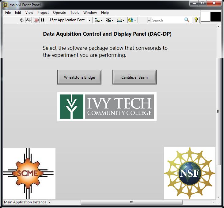
11 Our Projects? First up the Pressure Sensor kit => Modeling a Micro Pressure Sensor Kit R1 1kΩ R2 1kΩ VCC GND R3 1kΩ V1 5V R4 5kΩ 25 % Key=A A simulated wheatstone bridge VR Vref 3 2 VCC 4 7 GND U1 6 LM741CN Rf 1kΩ A0 The basic form of the DAC-DP shield 11


12 Our Projects? After many months 12


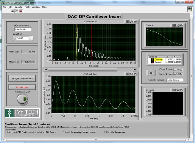

13 Our Projects? Second up the Cantilever Beam kit => Microcantilever Model Kit 13


14 Our Projects? And we had to build our own strain gauges What you will need How to make a strain gauge 1. Silhouette cameo 2. Computer with Silhouette studio 3. Silhouette pen holder 4. Electroninks Circuitscribe conductive ink pen 5. Common white printer paper 6. Kapton tape 1 wide 7. 30ga Magnet wire 8. 2x1 Female pin header/terminals 9. Conductive Wire glue 10. Strain gauge silhouette file 11. Silhouette grid cut file 14


15 Our Projects? More details Make the sensor 1. Plugin the silhouette cameo 2. Place the white printer paper onto the cutting mat aligning the top left corner of the paper with the top left corner of the cutting mat. 3. Load the cutting mat into the cameo 4. Set the blade height to 1 5. Load the blade into the cameo and secure in place 6. Open the grid cutting file on the computer in silhouette studio 7. Click send to silhouette 8. The cameo will now cut out the strain gauge backing pieces 9. Remove the blade from the cameo 10. Place the pen in the pen holder and tighten the screws to secure the pen in place 11. Place the pen/pen holder into the cameo and secure 12. Open the strain gauge file on the computer in silhouette studio 13. Click send to silhouette 14. The cameo will now draw the strain gauges 15. Remove the pen holder and clean any residue that it has collected on the pen tip 16. Repeat steps to draw a second layer onto the strain gauges. This will ensure that the ink is properly connected along the trace of the strain gauge. 17. Once it is done, tap the unload button on the cameo. 18. Set the cutting mat and strain gauges off to the side and let the ink dry for at least 30 minutes. 19. Remove the strain gauges DO NOT try to peel the strain gauges off of the cutting mat, the more that the strain gauge is bent or curled, the more variation or unreliable the strain gauge will be. Instead, Slide a long flat blade (pocket knife or razor blade) under each strain gauge to remove them from the adhesive, keeping the strain gauge as flat as possible 15


16 Our Projects? More details Prepare the wires 1. Cut two lengths of at least 6 of 30ga magnet wire 2. Use a knife to scrape the enamel off of both ends for ¼ 3. Use a crimp tool or pliers to connect a terminal to one end of each wire 4. Place the terminals into the 2 pin connector 5. Place an inch of heatshrink tubing over the pin header/wires 6. Use a heat source to shrink the tubing 7. Flatten the end of the tubing by the wire, this will allow for some flexibility and prevent the wires from breaking from too sharp of a bend. 8. Use a dab of wire glue to adhere the bare end of each wire to each pad of the strain gauge. 9. Wait at least an hour for the glue to cure 10. Cut a length of kapton tape 1.5 long 11. Place the tape centered over the strain gauge and perpendicular to the direction of the wires, being certain to align the top and bottom of the strain gauge with the edges of the tape. 12. Wrap the tape around the back of the strain gauge 13. You are done! 16

17 Our Projects? The process to develop a kit based on discovery based learning 1. Provide limits to the project with minimum design rules and objectives 2. Suggest student research the topic via the web 3. Suggest student conduct experiments to see what does and doesn't work 4. When student ask question only provide minimum suggestion unless they really need additional help. Also encourage group collaboration. 5. Provide feedback and remember the goal is learning. 6. Give the credit for the success and de emphasis the failures 17

18 Other Electronic Kits underdevelopment All kits developed to support collaboration class use for physics, electronics and engineering courses. New kits developed using same type of LabView code but new shields. The variable capacitor shield is based on the 555 timer and can be adapted to use the unused lid in the pressure kit. A prototype has been built for this new shield. 18
19 Other Electronic Kits underdevelopment The variable inductor shield will use an multi turn inductor wound around a cylinder either a another wound inductor or ferrite core will be placed inside the plastic cylinder and the center core will be displaced based on a fixed or moving mass. Current thinking is to use a simple buck converter topology to convert mass displacement into a unregulated DC which and be measured using the Arduino. The input AC could be generated using a 555 timer. 19
20 Conclusion Getting started with LabView and Arduino code More on SCME Kits nm.org/ More on Ivy Tech MEMS mems.org 20
ASSEMBLY, INSTALLATION, AND REMOVAL OF CONTACTS AND MODULES
 ASSEMBLY, INSTALLATION, AND REMOVAL OF CONTACTS AND MODULES FOR 75 OHM AND 75 OHM HD COAXIAL CONTACTS AND MODULES Table of Contents SECTION 1 RECEIVER CONTACT ASSEMBLY INSTRUCTIONS SECTION 2 ITA CONTACT
INSTALLATION INSTRUCTIONS RGB / RGBW 24V LED TAPE
 LLI-LCC4.4W LLI-LCCW4.4W LLI-LCCW5.8W **DANGER: Prior to installation, disconnect power at the source.** Make sure you have all components listed below: LED tape 24VDC Power Supply Connectors (if creating
INTRODUCTION (EE2499_Introduction.doc revised 1/1/18)
") INTRODUCTION (EE2499_Introduction.doc revised 1/1/18) A. PARTS AND TOOLS: This lab involves designing, building, and testing circuits using design concepts from the Digital Logic course EE-2440. A locker
INTRODUCTION (EE2499_Introduction.doc revised 1/1/18) A. PARTS AND TOOLS: This lab involves designing, building, and testing circuits using design concepts from the Digital Logic course EE-2440. A locker
Nixie Clock Type Frank 2 Z570M
 Assembly Instructions And User Guide Nixie Clock Type Frank 2 Z570M Software version: 7R PCB Revision: 11 April 09-1 - 1. INTRODUCTION 1.1 About the clock Nixie clock type Frank 2 is a compact design with
Multi-Key v2.4 Multi-Function Amplifier Keying Interface
 Multi-Key v2.4 Multi-Function Amplifier Keying Interface ASSEMBLY & OPERATION INSTRUCTIONS INTRODUCTION The Harbach Electronics, LLC Multi-Key is a multi-function external device designed for the safe
Philip Catterall: my Accessible Music Project
 Philip Catterall: my Accessible Music Project Presentation to MK Rotary, 1 open-source st February 2018 əʊp(ə)nˈsɔːs/ adjectivecomputing adjective: open-source denoting software for which the original
Azatrax Model Railroad Track Signal Control - Single Track
 Installation Guide Azatrax Model Railroad Track Signal Control - Single Track TS2 What it is: The TS2 operates one or two trackside block signals (one in each direction) on one track to simulate the block
VersaCap Lighting System
 VersaCap Lighting System Installation Instructions For Single Universe Lighting Systems Manual Version: V1.1 DFX 465 Taunton Avenue, Suite 108, West Berlin, NJ 08091 800-555-5280 www.dfxsoundvision.com
ELECTRICAL ADJUSTMENT INSTRUCTIONS
 ELECTRICAL ADJUSTMENT INSTRUCTIONS General Note: "CBA" is abbreviation for "Circuit Board Assembly." NOTE: Electrical adjustments are required after replacing circuit components and certain mechanical
Flat-Bed Module Recorders
 Flat-Bed Module Recorders Model No. 08376-50 08376-55 08376-60 0115-0192 4/28/00 Table of Contents Introduction...3 Power Requirements...3 Chart Paper Installation...3 Pen Installation...5 Grounding...5
Nixie Clock Type Frank 3
 Assembly Instructions And User Guide Nixie Clock Type Frank 3 Software version: 7R PCB Version: 11 April 09-1 - 1. INTRODUCTION 1.1 About the clock Nixie clock type Frank 3 is a compact design with all
Lesson Sequence: S4A (Scratch for Arduino)
") Lesson Sequence: S4A (Scratch for Arduino) Rationale: STE(A)M education (STEM with the added Arts element) brings together strands of curriculum with a logical integration. The inclusion of CODING in STE(A)M
Lesson Sequence: S4A (Scratch for Arduino) Rationale: STE(A)M education (STEM with the added Arts element) brings together strands of curriculum with a logical integration. The inclusion of CODING in STE(A)M
Alice EduPad Board. User s Guide Version /11/2017
 Alice EduPad Board User s Guide Version 1.02 08/11/2017 1 Table OF Contents Chapter 1. Overview... 3 1.1 Welcome... 3 1.2 Launchpad features... 4 1.3 Alice EduPad hardware features... 4 Chapter 2. Software
DEM 9ULNACK 3.4 GHz. PHEMT LNA amplifier complete kit assembly guide
 DEM 9ULNACK 3.4 GHz. PHEMT LNA amplifier complete kit assembly guide SPECIFICATIONS Noise Figure: < 0.8 db Gain: > 15 db Frequency Range: 3400-3500 MHz Input Voltage: 7-16 VDC Description: The 9ULNACK
DIY Guide - Building Franky v1.1, the SEGA Audio and Videocard for MSX
 DIY Guide - Building Franky v1.1, the SEGA Audio and Videocard for MSX 2015 FRS & MSXpró. Translation by FRS and Supersoniqs. Table of Contents Introduction... 3 Materials needed... 3 Audio volume boost...
Building the BX24-AHT
 Building the BX24-AHT file:///f /LASER/build-it.htm (1 of 8) [03/04/2002 5:21:52 PM] file:///f /LASER/build-it.htm (2 of 8) [03/04/2002 5:21:52 PM] Tips & Tricks Use a 25W or smaller soldering iron with
3. Electronics and MMU2 unit assembly
 Written By: Jakub Dolezal 2018 manual.prusa3d.com/ Page 1 of 34 Step 1 Tools necessary for this chapter Please prepare tools for this chapter: 2.5mm Allen key for M3 screws 2mm Allen key for nut alignment
Instruction Manual MODEL RSP SANITARY ELECTRONIC PRESSURE TRANSMITTER
 Instruction Manual Anderson Instrument Co. Inc. 156 Auriesville Road Fultonville, NY 12072 1-800-833-0081 Fax 518-922-8997 www.andinst.com Instrument Model Number Instrument Serial Number MODEL RSP SANITARY
HDBT Installation Guide
 KRAMER ELECTRONICS LTD. HDBT Installation Guide MODELS: Kramer HDBT Cable Recommendations for Usage and Termination Guidelines For the latest information on our products and a list of Kramer distributors,
Shane Tornifoglio Page 1 of 6. Weekly Report 6 2/29/10
 Shane Tornifoglio Page 1 of 6 Week 1 Feb 22 nd March 1 st This meeting marks the first meeting in three weeks because of no meeting the week before spring break and then bring break itself. The first week
Features. = +25 C, IF = 1GHz, LO = +13 dbm*
 v2.312 HMC6 MIXER, 24-4 GHz Typical Applications Features The HMC6 is ideal for: Test Equipment & Sensors Microwave Point-to-Point Radios Point-to-Multi-Point Radios Military & Space Functional Diagram
RECORD & PLAYBACK KIT
 TEACHING RESOURCES SCHEMES OF WORK DEVELOPING A SPECIFICATION COMPONENT FACTSHEETS HOW TO SOLDER GUIDE ADD AN AUDIO MESSAGE TO YOUR PRODUCT WITH THIS RECORD & PLAYBACK KIT Version 2.1 Index of Sheets TEACHING
Repair procedures Copyright DGT Projects 2005
 DGT Projects BV Repair procedures Copyright DGT Projects 2005 DGT 2000 Overview of versions The DGT 2000 has been produced since 1994. About 4 versions are in market. Main differences between the versions
The Haply Development Kit
 The Haply Development Kit Introduction The Haply development kit is a robust and adaptable open-source hardware development platform for haptic applications. Designed to be accessible to novices and experts
Samsung Galaxy J3 (2016) Screen
 Screen") Samsung Galaxy J3 (2016) Screen Replacement This guide shows how to replace the screen on your Samsung Galaxy J3 (2016). This includes the front glass, digitizer, and LCD panel. Written By: Arthur Shi
Samsung Galaxy J3 (2016) Screen Replacement This guide shows how to replace the screen on your Samsung Galaxy J3 (2016). This includes the front glass, digitizer, and LCD panel. Written By: Arthur Shi
Optimizing BNC PCB Footprint Designs for Digital Video Equipment
 Optimizing BNC PCB Footprint Designs for Digital Video Equipment By Tsun-kit Chin Applications Engineer, Member of Technical Staff National Semiconductor Corp. Introduction An increasing number of video
Documentation VFD clock 8 a clock
 Documentation VFD clock 8 a clock This documentation is protected by our copyright. It must not be used for commercial purposes. Congratulations on your purchase of your VFD clock. To guarantee success
Nixie Tube Clock Type Marsden
 Assembly Instructions And User Guide Nixie Tube Clock Type Marsden Software version: RTC-1.3 PCB Revision: 16 Aug 10-1 - 1. INTRODUCTION 1.1 About the clock Nixie clock type Marsden is a compact design
Dynamic Animation Cube Group 1 Joseph Clark Michael Alberts Isaiah Walker Arnold Li
 Dynamic Animation Cube Group 1 Joseph Clark Michael Alberts Isaiah Walker Arnold Li Sponsored by: Department of Electrical Engineering & Computer Science at UCF What is the DAC? The DAC is an array of
Reference Manual. Notes 9/16 Series H
 Reference Manual Notes 9/16 Series 173.01H Copyright notice The information in this document is subject to change without prior notice and does not represent a commitment on the part of Q-MATIC AB. All
NWRG Nixie Watch. User Manual
 NWRG Nixie Watch User Manual 2 Copyright (C) 2012 Cathode Corner. All rights reserved. Printed in USA Watch made in USA 3 Table of Contents Introduction... 5 Warranty... 7 Operating Instructions... 9 Maintenance...
Cable System Installation Guide
 Overview Cable System Installation Guide 5/19/2008 Our recommended approach for the installation of your Circle Graphics Cable Systems on the panels in your market is to install the fixed hardware (namely
AI-1664LAX-USB. Features. 100KSPS 16-bit Analog Input Unit for USB AI-1664LAX-USB 1. Ver.1.01
 100KSPS 16-bit Analog Unit for USB AI-1664LAX-USB * Specifications, color and design of the products are subject to change without notice. This product is a USB2.0-compliant analog input unit that extends
DIY KIT MHZ 8-DIGIT FREQUENCY METER
 This kit is a stand-alone frequency meter capable of measuring repetitive signals up to a frequency of 50MHz. It has two frequency ranges (15 and 50 MHz) as well as two sampling rates (0.1 and 1 second).
Analog Devices Welcomes Hittite Microwave Corporation NO CONTENT ON THE ATTACHED DOCUMENT HAS CHANGED
 Analog Devices Welcomes Hittite Microwave Corporation NO CONTENT ON THE ATTACHED DOCUMENT HAS CHANGED www.analog.com www.hittite.com THIS PAGE INTENTIONALLY LEFT BLANK v2.17 HMC55 MIXER, 11-2 GHz Typical
Bill of Materials: Magic Color PART NO
 Magic Color PART NO. 2193838 Magic color is a guessing game. With this game you can surprise your friends and leave them with amazement, how the game guesses what they have in their minds. Only two selections
W0EB/W2CTX DSP Audio Filter Operating Manual V1.12
 W0EB/W2CTX DSP Audio Filter Operating Manual V1.12 Manual and photographs Copyright W0EB/W2CTX, March 13, 2019. This document may be freely copied and distributed so long as no changes are made and the
Standard Operating Procedure of nanoir2-s
 Standard Operating Procedure of nanoir2-s The Anasys nanoir2 system is the AFM-based nanoscale infrared (IR) spectrometer, which has a patented technique based on photothermal induced resonance (PTIR),
Scan. This is a sample of the first 15 pages of the Scan chapter.
 Scan This is a sample of the first 15 pages of the Scan chapter. Note: The book is NOT Pinted in color. Objectives: This section provides: An overview of Scan An introduction to Test Sequences and Test
White Paper. Discone Antenna Design
 White Paper Discone Antenna Design Written by Bill Pretty Highpoint Security Technologies Property of Highpoint Security Technologies Inc The user of this document may use the contents to recreate the
Simulating Life on Your Layout
 by Brent Ciccone Simulating Life on Your Layout We have trains that move, but the rest of the layout is dead! Use lights and sound to simulate activity. Solid state methods, no moving parts. Lets start
C200H-AD002/DA002 Analog I/O Units Operation Guide
 C200H-AD002/DA002 Analog I/O Units Operation Guide Revised September 1995 Notice: OMRON products are manufactured for use according to proper procedures by a qualified operator and only for the purposes
3M Cold Shrink Splice Kit QS-III 5416A
 3M Cold Shrink Splice Kit QS-III 5416A for Jacketed Concentric Neutral (JCN) and Concentric Neutral Cable Instructions IEEE Std. 404 15 kv Class 150 kv BIL CAUTION Working around energized systems may
S op o e p C on o t n rol o s L arni n n i g n g O bj b e j ctiv i e v s
 ET 150 Scope Controls Learning Objectives In this lesson you will: learn the location and function of oscilloscope controls. see block diagrams of analog and digital oscilloscopes. see how different input
Field Service Procedure Replacement GACP Control Panel Kit, ST24
 1. Brief Summary: Troubleshooting document for diagnosing a fault with and replacing the Graphic Antenna Control Panel (GACP) for the ST24 antenna. 2. Checklist: Verify Power to the GACP Verify Communications
8 PIN PIC PROGRAMMABLE BOARD (DEVELOPMENT BOARD & PROJECT BOARD)
") ESSENTIAL INFORMATION BUILD INSTRUCTIONS CHECKING YOUR PCB & FAULT-FINDING MECHANICAL DETAILS HOW THE KIT WORKS LEARN ABOUT PROGRAMMING WITH THIS 8 PIN PIC PROGRAMMABLE BOARD (DEVELOPMENT BOARD & PROJECT
ESSENTIAL INFORMATION BUILD INSTRUCTIONS CHECKING YOUR PCB & FAULT-FINDING MECHANICAL DETAILS HOW THE KIT WORKS LEARN ABOUT PROGRAMMING WITH THIS 8 PIN PIC PROGRAMMABLE BOARD (DEVELOPMENT BOARD & PROJECT
Booya16 SDR Datasheet
 Booya16 SDR Radio Receiver Description The Booya16 SDR radio receiver samples RF signals at 16MHz with 14 bits and streams the sampled signal into PC memory continuously in real time. The Booya software
Cold Shrink Straight Joint
 Cold Shrink Straight Joint 3M QS2000E 22 kv Single Core Straight Joint Instruction Sheet All dimensions shown are in mm unless otherwise stated Kits contains components for one single core cable -2-2*
PRODUCT MANUAL. Product Description. Product Features. Manual will Review. LED Mini Neon 80W 24V DC. LED Mini Neon 80W 24V DC
 Product Description Thank you for purchasing Solid Apollo s! Solid Apollo s LED Mini Neon is a state of the art Neon LED lighting simulating the effect and look of neon in a thin continuous well-balanced
VGA Controller. Leif Andersen, Daniel Blakemore, Jon Parker University of Utah December 19, VGA Controller Components
 VGA Controller Leif Andersen, Daniel Blakemore, Jon Parker University of Utah December 19, 2012 Fig. 1. VGA Controller Components 1 VGA Controller Leif Andersen, Daniel Blakemore, Jon Parker University
UAV Ultimate Atari Video A7800
 UAV Ultimate Atari Video A7800 Basic Install guide because this is really easy mod to do! The UAV is a wonderful piece of tech for what it can do. To summarize, the UAV is a replacement video encoder and
3M Fiber Optic Splice Closure 2178-XSB/XSB-FR & 2178-XLB/XLB-FR 3M Cable Addition Kit 2181-XB/XB-FR
 3M Fiber Optic Splice Closure 2178-XSB/XSB-FR & 2178-XLB/XLB-FR 3M Cable Addition Kit 2181-XB/XB-FR Instructions July 2010 78-8135-0094-5-K 3 1.0 General 1.1 3M Fiber Optic Splice Closure 2178-XSB The
Features OBSOLETE. = +25 C, As an IRM. IF = MHz. Frequency Range, RF GHz. Frequency Range, LO
 v.17 Typical Applications The is ideal for: Microwave Radio & VSAT Test Instrumentation Military Radios Radar & ECM Space Functional Diagram Electrical Specifications, T A = +25 C, As an IRM Parameter
ipad Air 2 Wi-Fi Display Assembly Replacement
 ipad Air 2 Wi-Fi Display Assembly Replacement Fix a cracked or faulty screen by replacing the display assembly in an ipad Air 2 Wi-Fi. Geschreven door: Evan Noronha ifixit CC BY-NC-SA nl.ifixit.com Pagina
Integration of Virtual Instrumentation into a Compressed Electricity and Electronic Curriculum
 Integration of Virtual Instrumentation into a Compressed Electricity and Electronic Curriculum Arif Sirinterlikci Ohio Northern University Background Ohio Northern University Technological Studies Department
MUK REAR PANEL ASSEMBLY ASSEMBLY INSTRUCTIONS
 Rev B. 13 August 2017 ASSEMBLY INSTRUCTIONS The Midnight Ultimate Keyer (MUK) consists of two functional assemblies: Rear Panel containing the interface and power connectors. Front Panel containing the
TKEY-K16. Touch CW automatic electronic keyer. (No moving parts no contacts) Assembly manual. Last review: March 15, 2018
 Assembly manual. Last review: March 15, 2018") TKEY-K16 Touch CW automatic electronic keyer (No moving parts no contacts) Assembly manual Last review: March 15, 2018 Commands and use manual of the K16 and Updates and news: www.ea3gcy.com Thanks for
TKEY-K16 Touch CW automatic electronic keyer (No moving parts no contacts) Assembly manual Last review: March 15, 2018 Commands and use manual of the K16 and Updates and news: www.ea3gcy.com Thanks for
INSTRUMENT CATHODE-RAY TUBE
 INSTRUMENT CATHODE-RAY TUBE 14 cm diagonal rectangular flat face domed mesh post-deflection acceleration improved spot quality for character readout high precision by internal permanent magnetic correction
USER S MANUAL. FX2N-8AD Analog input block
 USER S MANUAL FX2N-8AD Analog input block FX2N-8AD Analog input block Foreword This manual contains text, diagrams and explanations which will guide the reader in the correct installation and operation
Mini LED Pixel Controller Part number: PX-SPI-mini
 Mini LED Pixel Controller Part number: PX-SPI-mini 11235 West Bernardo Court, Suite 102 San Diego, CA 92127 888-880-1880 Fax: 707-281-0567 EnvironmentalLights.com The Mini LED Pixel Controller provides
VITALink Taped Splice Straight Through Crimp
 A Marmon Wire & Cable Berkshire Hathaway Company VITALink Taped Splice Straight Through Crimp 2 Hour Fire-Rated Splice VITALink MC Cables, UL FHIT 120 Installation Instructions Description The VITALink
COLOUR CHANGING USB LAMP KIT
 TEACHING RESOURCES SCHEMES OF WORK DEVELOPING A SPECIFICATION COMPONENT FACTSHEETS HOW TO SOLDER GUIDE SEE AMAZING LIGHTING EFFECTS WITH THIS COLOUR CHANGING USB LAMP KIT Version 2.1 Index of Sheets TEACHING
Tube Cricket Build Guide
 Tube Cricket Build Guide The Tube Cricket is a small-wattage amp that puts out about 1 watt of audio power. With a 12AU7 tube-preamp and a JRC386 power amp, the Tube Cricket gives you great tone in a compact
2178-L/S Series Fiber Optic Splice Case with Gasket
 2178-L/S Series Fiber Optic Splice Case with Gasket Instructions for: 2178-S Splice Case 2178-LS Splice Case 2178-LL Splice Case 2181-LS Cable Addition Kit May 1997 34-7041-9949-5-A 1 Table of Contents
Self-Playing Xylophone
 Self-Playing Xylophone Matt McKinney, Electrical Engineering Project Advisor: Dr. Tony Richardson April 1, 2018 Evansville, Indiana Acknowledgements I would like to thank Jeff Cron, Dr. Howe, and Dr. Richardson
Automatic Connector MHV Connectors MHV Introduction MHV series connectors Contents Polarized mating interfaces Anti-Rock mating interfaces
 Automatic s 2004 Automatic. All rights reserved. pdf 1.0 3-18-04 Contents Specifications........................... 2 Straight Cable Plugs...................... 3 Right Angle Cable Plugs...................
HC20 Healthcare Kit Installation Instructions
 Our HC20 installation kit uses technology that allows a standard hospital pillow speaker to control a TV and receive audio from the TV at the pillow speaker next to the patient. The HC20 product, when
Christmas LED Snowflake Project
 Christmas LED Snowflake Project Version 1.1 (01/12/2008) The snowflake is a follow-on from my Christmas star project from a few years ago. This year I decided to make a display using only white LEDs, shaped
3M Cold Shrink Splice Kit QS-III 5515A
 3M Cold Shrink Splice Kit QS-III 5515A for UniShield, Wire Shielded, Longitudinally Corrugated (LC), and Tape Shielded (Ribbon Shielded) Cable or Transitions to Concentric Neutral (CN)/Jacketed Concentric
IPad 3 (glass) REPAIR GUIDE. Version Edition
 REPAIR GUIDE. Version Edition") IPad 3 (glass) REPAIR GUIDE Version 1 2016 Edition IPad 4 REPAIR GUIDE LCD AND DIGITIZER REPLACEMENT RiAna Soto Repair Training Specialist rsoto@cellairis.com FOR EVERY REPAIR MAKE SURE TO COMPLETE, INITIAL,
IPad 3 (glass) REPAIR GUIDE Version 1 2016 Edition IPad 4 REPAIR GUIDE LCD AND DIGITIZER REPLACEMENT RiAna Soto Repair Training Specialist rsoto@cellairis.com FOR EVERY REPAIR MAKE SURE TO COMPLETE, INITIAL,
Introduction Front Panel Functions Rear Panel Functions Precautions Placement & Ventilation... 5
 Contents Introduction... 2 Front Panel Functions... 3 Rear Panel Functions... 3 Precautions... 5 Placement & Ventilation... 5 Installation & Operation... 5 Care & Maintenance... 7 Troubleshooting... 8
Features. = +25 C, IF = 1 GHz, LO = +13 dbm*
 v.5 HMC56LM3 SMT MIXER, 24-4 GHz Typical Applications Features The HMC56LM3 is ideal for: Test Equipment & Sensors Point-to-Point Radios Point-to-Multi-Point Radios Military & Space Functional Diagram
K Service Source. Apple High-Res Monochrome Monitor
 K Service Source Apple High-Res Monochrome Monitor K Service Source Specifications Apple High-Resolution Monochrome Monitor Specifications Characteristics - 1 Characteristics Picture Tube 12-in. diagonal
AI-1616L-LPE. Features. High-precision Analog input board (Low Profile size) for PCI Express AI-1616L-LPE 1. Ver.1.02 Ver.1.01
 for PCI Express AI-1616L-LPE 1. Ver.1.02 Ver.1.01") High-precision Analog input board (Low Profile size) for PCI Express AI-1616L-LPE This product is a multi-function, PCI Express bus-compliant interface board that incorporates high-precision 16-bit analog
High-precision Analog input board (Low Profile size) for PCI Express AI-1616L-LPE This product is a multi-function, PCI Express bus-compliant interface board that incorporates high-precision 16-bit analog
Introduction 1. Green status LED, controlled by output signal ST. Sounder, controlled by output signal Q6. Push switch on input D6
 Introduction 1 Welcome to the GENIE microcontroller system! The activity kit allows you to experiment with a wide variety of inputs and outputs... so why not try reading sensors, controlling lights or
V6118 EM MICROELECTRONIC - MARIN SA. 2, 4 and 8 Mutiplex LCD Driver
 EM MICROELECTRONIC - MARIN SA 2, 4 and 8 Mutiplex LCD Driver Description The is a universal low multiplex LCD driver. The version 2 drives two ways multiplex (two blackplanes) LCD, the version 4, four
Fig. 1. The Front Panel (Graphical User Interface)
") ME 4710 Motion and Control Data Acquisition Software for Step Excitation Introduction o These notes describe LabVIEW software that can be used for data acquisition. The overall software characteristics
ME 4710 Motion and Control Data Acquisition Software for Step Excitation Introduction o These notes describe LabVIEW software that can be used for data acquisition. The overall software characteristics
BASIC LINEAR DESIGN. Hank Zumbahlen Editor Analog Devices, Inc. All Rights Reserved
 BASIC LINEAR DESIGN Hank Zumbahlen Editor A 2007 Analog Devices, Inc. All Rights Reserved Preface: This work is based on the work of many other individuals who have been involved with applications and
Data Acquisition Using LabVIEW
 Experiment-0 Data Acquisition Using LabVIEW Introduction The objectives of this experiment are to become acquainted with using computer-conrolled instrumentation for data acquisition. LabVIEW, a program
E-TEXTILES STARTER PACK
 LEARN HOW TO SEW A CIRCUIT WITH THIS E-TEXTILES STARTER PACK WHITE LEDs BLUE LEDs LARGE COIN CELL MINIATURE COIN CELL SEWABLE ELECTRONICS INTRODUCTION TO ELECTRO-FASHION Electro-Fashion is Kitronik's own
Session 1 Introduction to Data Acquisition and Real-Time Control
 EE-371 CONTROL SYSTEMS LABORATORY Session 1 Introduction to Data Acquisition and Real-Time Control Purpose The objectives of this session are To gain familiarity with the MultiQ3 board and WinCon software.
DEVELOPMENT OF LABVIEW BASED WIRELESS CONTROL SYSTEMS FOR ION BEAM MICROMACHINING SYSTEMS
 International Journal of Scientific & Engineering Research, Volume 3, Issue 11, November-2012 1 DEVELOPMENT OF LABVIEW BASED WIRELESS CONTROL SYSTEMS FOR ION BEAM MICROMACHINING SYSTEMS Mr. JOSHI TUSHAR
Music-Visualization and Motion-Controlled LED Cube
 Music-Visualization and Motion-Controlled LED Cube 1 Introduction 1.1 Objective Team 34: Hieu Tri Huynh, Islam Kadri, Zihan Yan ECE 445 Project Proposal Spring 2018 TA: Zhen Qin Our project s main inspiration
Figure 1. MFP-3D software tray
 Asylum MFP-3D AFM SOP January 2017 Purpose of this Instrument: To obtain 3D surface topography at sub-nanometer scale resolution, measure contact and friction forces between surfaces in contact, measure
RK-2 ENVIRONMENTAL DATA CONTACTLESS MAGNETOSTRICTIVE LINEAR POSITION TRANSDUCER WITH FLANGED HEAD. Main characteristics
 RK-2 CONTACTLESS MAGNETOSTRICTIVE LINEAR POSITION TRANSDUCER WITH FLANGED HEAD (ANALOG OR START/STOP OUTPUT) Main characteristics Absolute transducer Strokes from 50 to 4000mm (RK-2- -N/E/S) Digital output
3M Cold Shrink Splice Kit QS-III 5514A
 3M Cold Shrink Splice Kit QS-III 5514A for UniShield, Wire Shielded, Longitudinally Corrugated (LC), and Tape Shielded (Ribbon Shielded) Cable or Transitions to Concentric Neutral (CN)/Jacketed Concentric
Prototyping & Engineering Electronics Kits Magic Mandala Kit Guide
 Prototyping & Engineering Electronics Kits Magic Mandala Kit Guide odysseyboard.com Please refer to www.odysseyboard.com for a PDF updated version of this guide. Magic Mandala Guide version 1.0, February,
3M Cold Shrink QS4 Integrated Splice Kit QS4-15JCN
 3M Cold Shrink QS4 Integrated Splice Kit QS4-15JCN-500-1000 for Jacketed Concentric Neutral (JCN) and Flat Strap Neutral Cable Instructions IEEE Std. 404 15 kv Class 150 kv BIL F CAUTION Working around
Directional Couplers and Splitters
 Directional couplers and splitters divide trunk and feeder lines. 17-Amp current handling capacity. Excellent hum-modulation performance. 1/2-inch hard-line ports have extra length, creating a better seal
Quick Start ATOMIC FORCE MICROSCOPE West Campus Imaging Core
 Quick Start ATOMIC FORCE MICROSCOPE West Campus Imaging Core 1 Turn On the laser power 2 Open enclosure: - lift the door latch and open the enclosure door. 3 2 1 1.Unlock scanner: Lift the lever to the
Building a MidiBox LCD Cable
 Building a MidiBox LCD Cable By Jim Henry, 3-Apr-2004 An LCD panel may be connected to the Core module by a 16 conductor flat ribbon cable. A 16 pin insulation displacement connector (IDC) terminates one
LX3V-4AD User manual Website: Technical Support: Skype: Phone: QQ Group: Technical forum:
 User manual Website: http://www.we-con.com.cn/en Technical Support: support@we-con.com.cn Skype: fcwkkj Phone: 86-591-87868869 QQ Group: 465230233 Technical forum: http://wecon.freeforums.net/ 1. Introduction
OpenXLR8: How to Load Custom FPGA Blocks
 OpenXLR8: How to Load Custom FPGA Blocks Webinar Breakdown: Introduc*on to pseudorandom number generator (LFSR) code Review of Verilog wrapper interface to microcontroller Simula*on with Mentor Graphics
Multi-Media Installation Guide
 Multi-Media Installation Guide Coaxial Page 2 Data Plug Page 7 Data Jack Page 10 Telephone Page 13 Splicing Page 15 Cable Types Cable Types Two basic types of cable are used in multimedia installations.
DSO138mini Troubleshooting Guide
 DSO138mini Troubleshooting Guide Applicable main board: 109-13800-00I Applicable analog board: 109-13801-00H 1. Frequently Found Problems 1) LCD completely dark. No backlight 2) LCD lights up but no display
Report on 4-bit Counter design Report- 1, 2. Report on D- Flipflop. Course project for ECE533
 Report on 4-bit Counter design Report- 1, 2. Report on D- Flipflop Course project for ECE533 I. Objective: REPORT-I The objective of this project is to design a 4-bit counter and implement it into a chip
MACH3 LaserAce Installation Manual Revision 1. MACH3 LaserAce Installation Manual
 WWW.LASERARCADE.COM MACH3 LaserAce Installation Manual Revision 1 MACH3 LaserAce Installation Manual Table of Contents Introduction...1 Parts supplied with MACH3 FNI...1 Why the MACH3 FNI is required...2
Fixture Production Equipment and Fixtures
 Our Complete Solution incl. Fixturing A test system, whether for In-circuit or for Function test, can only be used in a reasonable way, if the item under test, PCB, hybrid, module or SMT-PCB, can be connected
EAGLE RE-1 CONTROLLER
 EAGLE RE-1 CONTROLLER For Use On ALL MotoSAT Mounts Supported Systems HD SL5 DirecTV HD DP3 Dish Network HD SC2 SHAW HD DP3 BELL TV EXECUTIVE 18" DirecTV 101 Dish Network 119 MSC-60 SHAW MD-500 Dish Network
1 Output 1 operation. 3 Pressure unit display. 4 Main display Large 4-character LCD display. 5 Sub-display Small 4-character LCD display.
 ure Sensor DP-100 Series INSTRUCTI MANUAL High-performance Digital Display For use outside Japan MEUML-DP100 V1.1 Thank you for purchasing products from Panasonic Electric Works SUNX Co., Ltd. Please read