PROGRAMMING. Version Author: Vandermeerschen M. 2.07
|
|
|
- Molly McBride
- 5 years ago
- Views:
Transcription

1 PROGRAMMING Author: Vandermeerschen M. Version 1


2 PROJECTS Apartments and hotels Houses Agriculture/gardening Service flats Company buildings Meeting rooms and home theatres Stores/malls Healthcare Museums 2
3 APPARTMENT HOME THEATRE HOUSE COMMERCIAL 3

4 APARTMENT Star wiring a b c a b c +24VDC ADD-ON CABLE a b c 4

5 CARE APPARTMENT Key switch Bathroom Light sensor switch Entrance Peak rate intercomunale Motorcontroller Luxom temperature sensor a b c a b c KWH meter Door bel Patio lights Sunscreen up Sunscreen down Storage door contact Button day Button sleep Button moods Button cooking Panic button 5
6 APPARTMENT HOME THEATRE HOUSE COMMERCIAL 6
7 HOME THEATRE 7
8 HOME THEATRE - OUTPUTS 1x 1x 1x 4x 1x 1x 8
9 HOME THEATRE - INPUTS 4x 1x 1x 9

10 HOME THEATRE - MODULES RJ45 IR Receiver 10

11 WIRING 4 CH.DIMMER DS704A 1 11


12 WIRING 4 CH.RELAY MODULE DS04A 2 3 OPTIONAL: Pulse to MRC400 12
13 ADDRESSING 13
14 ADDRESSING Physical address = MIN Module Identiffication Number Bus address = For the in- and outputs Available : 4096 = 16 (0 F) x 256 (00 FF) Commands : Toggle Set Clear Analog + Zx Ping Telegram : *T,0,2,81; 14
15 PLUSCONFIG Physical address (MIN numbers + Location of the modules) BUS address 15

16 REGISTER YOUR PLUSCONFIG 16
17 ADD MODULES (OFF-LINE / ON-LINE) 4 ways to commission a Luxom project: - Create modules off-line in the PlusConfig software. (with or without a configuration) - Assign the MIN numbers to the modules in the office. The configuration is done on-site. - MIN numbers + configuration of the modules is done in the office. - MIN numbers + configuration of the modules is done on-site. You may only start to configure a module after all modules in your project have been recognised by your computer. 17

18 CONNECT OVER IP IP : BUS Ethernet CAT 5 IP : xxx ( ) 18
 4- Push shortly on the MIN button of the first module 2-")

19 HOW TO ADD A MODULE? 1- Clik Add new module(s) 4- Push shortly on the MIN button of the first module 2- Choose the MIN number 3- Clik Start 5- Before pushing on the MIN button of the second module you have to make shure that the MIN led is OFF of the previous module Repeat these 5 steps until all modules are recognised and then you click Stop 19
20 HOW TO ADD THE CINCO? Step 1: Push on the Lower button Step 2: Keep pushing on the Lower button while pushing 3 seconds on the Upper button to activate the MIN programming mode. Step 3: Release the buttons when the RGB led s start flashing RED. 20


21 CHANGE NAME MODULES Right mouse click on module -Name - Reference -MIN - Type -Partnr -PID 21

22 CHANGE VIEW MODULES -Name - Reference -MIN - Type -Partnr -PID 22
23 VIEW MODULES 23


24 FORMAT MODULES Step 1- Select Home theatre Step 2- Click in the menubar Step 3- Select YES 24

25 WRITE CHANGED PROPERTIES Write changed properties to module Write properties to module 25
26 STATES OF THE MODULES Module is not connected onto the bus, or MIN number has not been assigned to the module Module OK Configuration shown onto your screen still need to be written to the module Click onto this icon to know the MIN number of the module. (MIN LED has to blink before you click this icon) Module in programming mode (MIN led blinks) The lightning only disappears after Ping module 26

27 DIMCONTROLLER Channel 1 : Front lights -Channel 2 : Rear lights -Channel 3 : Center lights -Channel 4 : Left + Right lights -Channel 5 : Projection screen up -Channel 6 : Projection screen down -Channel 7 : Curtains open -Channel 8 : Curtains close -Channel 9 : Projector lift -Channel 10 : A/V rack power -Channel 11 : Floor LEDs -Channel 12 : Motion sensor power HOME THEATRE 27


28 HOW TO ADD A BUS ADDRESS? 1- Clik New address 2- Give it a Type/Name/Address 3- Clik Add to add this addres in the address list: 28


29 HOW TO IMPORT BUS ADDRESSES? 29
30 DIMCONTROLLER ADD-ON 1 30

31 DIMCONTROLLER ADD-ON 2 31
32 DIMCONTROLLER ADD-ON 3 32
33 TEST Select the BUS address and click... Ping (status?) Set (ON) Toggle Start BUS monitor Clear (OFF) Ping status feedback 33
34 COMMANDS T S 1 = ON = 100% C 0 = OFF = 0% T T Master: Slave: T S ON T C OFF P S... C... A S/C C/S Set Clear Clear Set P S...C T/T Toggle Toggle P or T 34
35 COMMANDS LED Feedback Push button T BUS RS VAC L N S... C... A 35
36 OTHER TEST FEATURES Ping module Ping BUS address ( ) Ping MIN number module ( ) BUS signal level Reset module BUS Monitor 36

37 BUSMONITOR Translation mode active Translation mode not active 37
38 OUTLINKS - MOODS - TIMED MOODS OUTLINKS : Available in output modules : SWITCH MODULES (DS04L DS08L DS88L) MOODS : Available in output modules : CONTROLLERS (DS10C-DS20C-DS10CCL) TIMED MOODS : Available in new generation input modules (DS03LX) 38
39 OUTLINKS - MOODS - TIMED MOODS MOODS & OUTLINKS = Local output macro Where? These software features are present in the output modules. Controllers = MOODS Relay modules = OUTLINKS Advantages: - Fast to configure - Decentralised. Disadvantages : Only the local outputs of the module can be part of the Mood or Outlink Applications? - Small size projects (home theatre, ) - Commercial projects (>outputs <inputs) TIMED MOODS = Bus address macro Where? Timed moods are present in the new generation input modules. Advantages: - Easy to add an address - Not module type related.( C, %, On/off, ) - Easy to add delays between addresses Disadvantages: Centralised, the addresses are generated by one module. Applications? - Medium size projects - Projects that are often modified 39
40 OUTLINKS - MOODS - TIMED MOODS MOODS & OUTLINKS = Local output macro TIMED MOODS = Bus address macro Where? These software features are present in the output modules. Controllers = MOODS Relay modules = OUTLINKS Advantages: - Fast to configure - Multi-process Disadvantages: Only the local outputs of the module can be part of the Mood or Outlink Applications? - Small size projects (home theatre, ) - Commercial projects (>outputs <inputs) Where? Timed moods are present in the new generation input modules. Advantages: - Easy to add an address - Not module type related. (can send C, %, On/off, ) - Easy to add delays between addresses Timed moods can be combined with Moods & Outlinks. A Timed mood can activate a Mood or Outlink! Disadvantages: - Not multi-process, the addresses are generated by one module. Applications? - Medium size projects - Projects that are often modified 40

41 MOODS IN DS20C MOODS DS20C 41
42 MOOD HT ALL OFF New address SET DS20C 42
43 MOOD HT ALL ON New address SET DS20C 43
44 Solution A: MOOD Start projection 1sec 15sec DS20C 44


45 Solut. B: TIMED MOOD Start projection DS03LX 45
46 Solution A: MOOD Stop projection 1sec 15sec 60sec DS20C 46
47 Solution A: MOOD Stop projection This mood is to prevent that the relays stay on when it s no longer necessary DS20C 47


48 Solut. B: TIMED MOOD Stop projection DS03LX 48

49 MOOD Step ±10% New address + 10% (SET) - 10% (CLEAR) SET CLEAR 2 button control DS20C 1 button control 49
 2- Program the mood push button as S/C")
50 MOOD Learnable! < 1 sec = call mood > 5 sec = learn mood New address in S/C mode Procedure: 1- Set mood as 2- Select the outputs in the mood (the lightlevels are not important) 2- Program the mood push button as S/C 3- Change lightlevels in the room by using push buttons or a remote control 4- Push 5sec on the mood button to learn 5- Read out the mood settings for backup 6- Change mood button to Set so the customer can t change the mood. DS20C 50


51 INPUTS - Motion sensor LU0400 The motion sensor is connected to binary input 1 and controls the floor Leds. Motion: Leds ON - No motion + delay (in LU0400): Leds OFF DS20C 51
 LU0400 DS20C 52")
52 INPUTS 4 push buttons (on the wall) LU0400 DS20C 52


53 INPUTS IR receiver DS34LM 53
54 OTHER EXAMPLES 54

55 HOME THEATRE WITH TP & fluoresc. DS32L/422 Cat 5 IR FLASHERS 16VDC Xantech SPLCD MOOD 1-5 Dimcontroller a b a b c 55


56 BOARDROOM Crestron / AMX / Vity... LAN MOOD 1-5 Dimcontroller a b c a b c 56
57 APPARTMENT HOME THEATRE HOUSE COMMERCIAL 57
58 HOUSE Star wiring Motorcontroller a b c d e f a c e b d f 58

59 HOUSE Buswiringtype I Feedback x10 <-> a b a b 59

60 HOUSE Bus wiring type II Feedback x10 <-> a Motorcontroller a b b c d c d DCF receiver 60
61 HOUSE Buswiring type III Feedback x10 <-> Dimcontroller Motorcontroller a b c d a b c d e f DCF receiver e f 61
62 HOUSE Buswiring type IV Feedback x10 <-> Dimcontroller Motorcontroller a b c d a b c d e f e f 62


63 HOUSE Buswiring type V a b c d e 63 d a b e Dimcontroller Motorcontroller x10 f c IR f


64 VILLA g h g h a b c a b c d e f d e 64 f
65 WORKSHOP HOUSE 65
66 HOUSE - OUTPUTS L R 18x 4x 1x 2x 4x 2x 2x 66
67 HOUSE inputs : Cabinet : DS03LX modules : Buscable : Cable to input(s) DS03LX or MT210 N zones = ± total of DS03LX and MT210 67


68 MODULES WIRING LAN Bathroom Lounge MT210 DS03LX Master bedroom DS30L LU

69 GROUP MODULES IN TREEVIEW 69

70 RELAYMODULE DS08L a -Channel 1 : Master bedroom wall light -Channel 2 : Master bedroom bed right -Channel 3 : Master bedroom bed left -Channel 4 : Bathroom light -Channel 5 : Bathroom ventilation -Channel 6 : Toilet ventilation -Channel 7 : Kitchen sink power socket -Channel 8 : Terrace power socket a a -Channel 9 : Storage space -Channel 10 : Study -Channel 11 : Lounge heating I/0 -Channel 12 : Bathroom heating I/0 70
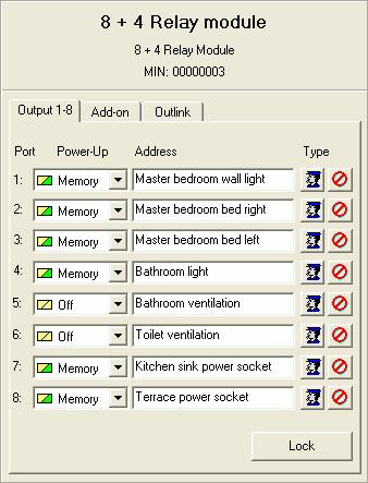
71 RELAYMODULE DS08L 71

72 RELAYMODULE DS08L Add-on 72
73 CINCO CINCO 73
74 CINCO button 74
75 CINCO button 75
76 CINCO - button = Ping = Clear = Toggle (**) Repeat status every xx seconds = Set = analoge data ( C, %, ) = Set = Clear = Set (**) = Clear(**) = Set.. t..clear = Clear = Set = Clear (**) = Set (**) = Clear.. t..set = Toggle = Toggle = Timed 76 mood (1 20 select on name)


77 CINCO 4 shift pages 77
78 CINCO Copy color 78

79 CINCO Change color 79
80 CINCO Change custom color palette Step 1: Select color Step 2: Choose color: Step 3: Select Adjust Custom Color to save the color 80

81 CINCO Send color from 1. Timed mood: Fading time 2. Input: 81

82 CINCO All buttons page 82
83 CINCO Change shift page 1. Set on the Shift address: Val on the Shift address: Timed mood: Input: 1 = Go to shift page 1 Set = next page Clear = previous page 2 = Go to shift page 2 3 = Go to shift page 3 4 = Go to shift page 4 83
84 CINCO Feedback If you use a LED for status feedback (of an output), we advise to stay in the same color, but with a different luminance 84

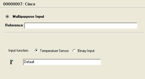
85 CINCO Multipurpose input 85

86 CINCO Learn mood With this function Learn mood you can change the content of a mood by pushing long on this push button. You can learn I/0 - C - % - 86

87 CINCO Gobal module settings 87

88 CINCO Byte control - 1 Byte: DIM LED 0 100% (*A,0,g,aa;*Z,0dd;) - 2 Byte: DIM LED + Fading time - 3 Byte : R G B - 4 byte : R G B + Fading time F.ex: Put global color to red in 0sec at 50% brightness with short press: 88

89 DIMCONTROLLER DS20C a b c a b c a -Channel 1 : Lounge downlighters left -Channel 2 : Lounge downlighters right -Channel 3 : Lounge downlighters central -Channel 4 : Lounge uplighter c -Channel 9 : Store room 1 ste floor -Channel 10 : Staircase night light -Channel 11 : Dressing -Channel 12 : Dining room b -Channel 5 : Toilet light -Channel 6 : Bedroom 1 children -Channel 7 : Bedroom 2 spare room -Channel 8 : Night hall 89

90 DIMCONTROLLER Add-on 1 Slave Master Master Memory 90
91 DIMCONTROLLER Add-on 2 91
92 DIMCONTROLLER Add-on 3 92
93 10 I/O EVENT MODULE LOUNGE Lounge 93

94 DS03LX Lounge - Press SHORT/LONG Reference= Location push button 94

95 SHORT 2x 3x SETUP TIME 95

 Change View")

96 DS03LX rename module Rename module (right click module in treeview) Change View (menubar) View properties module: (double click on module) 96


97 MOTORCONTROLLER DS10C-CL a b c a b c a b c -Channel 1a : Kitchen downlighters -Channel 1b : Garage fluorescent -Channel 2a : Entrance hall -Channel 2b : Terrace spots -Channel 3a : Lounge shutter streetside (L+R) up 3b : streetside (L+R) down -Channel 4a : Lounge shutter garden up 4b : Lounge shutter garden down -Channel 5a : Master bedroom up -Channel 6a : Kitchen sunblinds up 5b : Master bedroom down 6b : Kitchen sunblinds down 97

98 MOTORCONTROLLER Add-on 1 Blinds = up/down/stop Shutter = up/down/stop & % 98
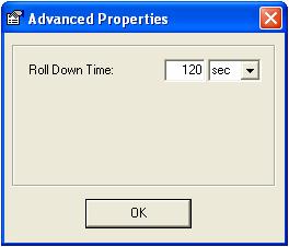
99 MOTORCONTROLLER Add-on 2 99
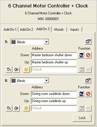
100 MOTORCONTROLLER Add-on 3 100
101 Setup shift DS03LX SHIFT DS03LX 101
102 DS03LX SETUP SHIFT With this address you activate/deactivate the shift mode 102
103 DS03LX Go into shift mode No Shift page Channel 4 is used to activate/deactivate the shift mode. 103
104 DS03LX Go out of the shift mode Shift page If you don t configure this you can t go out of the shift mode 104

105 DS03LX SHIFT LED
 the Master bedroom shutter")
106 DS03LX SHIFT In this example you control in the No Shift mode the Master bedroom wall light, and in the Shift mode (with the same button) the Master bedroom shutter up. 106
107 No Shift Master bedroom wall light Master bedroom bed left Master bedroom bed right Shift mode on/off Shift Master bedroom shutter up Master bedroom shutter down Night hall Shift mode on/off 107
108 108 No Shift Shift

109 STAIRCASE TIMER IN DS03LX 109

110 SHORT 2x 3x LONG PRESS 110
111 Setup sensors SENSORS 111
112 Setup binary input With a contact from an alarm system: Alarm system Armed (absence) Disarmed (presence) Luxom system binary input S/C S= Armed C= Disarmed 112
113 Setup alarm system - armed/disarmed Alarm system armed? disarmed? DS20C 113
114 Setup alarm system - sirene Sirene On? Off? DS20C 114

115 Setup contact garage door Garagedoor: Closed? Open? DS20C 115
116 Setup temperature C - Lounge! Temperature sensor in the Lounge!! DS30L 116


117 Setup temperature C - Bathroom Temperature sensor in the bathroom Temperatuur offset: 117

118 Changing C requested 3 ways to change the requested temperature: a b SET = C CLEAR = C Analogue value xx C c SET REGIME With LED s configured on these addresses you can visualize the active regime. Note: If you want to be able to change the temperature of a regime through the PlusView software you have to setup the address type as: [Temperature setting C] DS30L 118
119 0-10V sensor! Every 10 seconds the analog value measured on input A1 is send to the Luxom network. DS20C 119
120 0-10V Light level 120

121 Windspeed Km/h! DS10C-CL 121

122 Windspeed low & high alarm! Set Windspeed low alarm is send when >30km/h, Clear command when <30km/h for minimum 20 minutes.! Set Windspeed high alarm is send when >80km/h, Clear command when <80km/h for minimum 20 minutes. DS10C-CL 122


123 Setup Master System Clock Step! This address has to be setup in all DS10C-CL and DS03LX modules. 1x DS10C-CL Master, all others Slave! 3 DS10C-CL 123
124 Setup Slave Clock in DS03LX & Cinco DS03LX 124

125 Setup Slave System Clock 125

126 Setup Slave System Clock 126
127 PlusView PlusView 127

128 PLUSVIEW Use PlusView to visualize all sensors, inputs & outputs 128

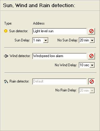
129 PLUSVIEW Create your own user interface, import home made icons and backgrounds. 129
130 Panic function Panic function 130


131 Panic function in MOOD SET = panic CLEAR = return to normal mode New address!! DS10C-CL DS20C 131
132 Panic function in OUTLINK SET = panic CLEAR = return to normal mode DS08L DS08L 132
133 Timers in Outlink Timers in Outlink 133
134 TIMERS IN DS08L (OUTLINK) Staircase timer storage space Option 1: New address DS08L 134
135 TIMERS IN DS08L Staircase timer storage space Option 2 (smart version) : Application for cellar lights, attic lights 30min 60min 135
136 TIMERS IN DS08L Set bathroom fan ON when lights bathroom are ON for 10min DS08L 136


137 TIMERS IN DS08L When bathroom lights are turned OFF, turn bathroom fan OFF after 4 min DS08L 137
138 Setup lock LOCK 138

139 LOCK OUTPUT (Terrace spots) Use 2 push buttons: 1 to toggle the Terrace spots 1 to toggle the Terrace spots lock. UseanLED in Slavebehindeach push button to provide feedback to the customer. Light on?... Lock on?... This allows the customer to lock the lights in the ON position and in the OFF position! New address SET = Lock ON CLEAR = Lock OFF TOGGLE = ON OFF 139

140 LOCK INPUT (in DS03LX) SET = Lock ON CLEAR = Lock OFF TOGGLE = ON OFF Every input in the DS03LX module can be locked. This feature is used to disable push buttons or motion sensors connected to this input. This makes it very easy to f.ex. disable a motion sensor in the living room during the period that the home cinema scene is active. 140
141 Motor controlwithsun wind rain SUN - WIND - RAIN 141

142 WIND Listen to the windspeed alarm Do not listen to the windspeed alarm 142

143 SUN Assign level to motorcontroller DS20C Create level in the dimcontroller DS10C-CL 143
144 Sun detection ON OFF Manual override If not enabled, manual control of the motor is not possible when sun detection is active. Set : Sun detection On Clear : Sun detection Off Toggle : On Off 144
145 Timed mood TIMED MOOD 145
146 Setup TIMED MOODS L R 146

147 Setup TIMED MOODS L R 5 Go to bed 3 6 Wake up OFF 7 Go out 1 OFF 2 OFF 4 OFF 8 Go out when dark 9 Coming home day 10 Coming home dark 11 Light route to kitchen 147

148 TIMED MOOD 1a - OFF lounge +... Trigger Address START : SET STOP : CLEAR DS03LX 148

149 TIMED MOOD - SPECIAL PROPERTIES Internal use mood only : Timed mood can not be started/stopped with an address This mood belongs to a moodgroup : See next page Start this mood on power-up : Timed mood starts 20 sec after reboot of the module. (Time can be changed in the Global module settings ) Each Timed mood can be: Running = when the mood is started and the last action has still to be executed Active = when the Timed mood is started and Stop is not been received A mood can be started by: - A local input on the module -A SET command on the trigger address of the Timed mood - A True or False action from a LogiX - Another Timed mood A mood can be stopped by : - A CLEAR command on the trigger address of the Timed mood - A True or False action from a LogiX - Another Timed mood 149


150 TIMED MOOD - MOODGROUP With the moodgroup function you can interconnect Timed moods. With this function no more then one Timed mood can be active at the same time in the same moodgroup. When you start a Timed mood that is part of a moodgroup the module will stop the previous active Timed mood. Step 1 Check the checkbox This mood belongs to a moodgroup in all Timed moods who have to belong to the same group: Step 2 Select a MoodGroup (1...15) : (setup the same n in all timed moods who have to be interconnected!) 150

151 TIMED MOOD 1b - OFF lounge +...! DS03LX 151

152 TIMED MOOD 2 - OFF gar.+ kitch... To make sure that the terrace lights can be turned Off, we first have to turn the lock Off before we can turn the Terrace lights Off. This guarantees that the terrace lights will be Off even when the lock was turned On previously. 152

153 TIMED MOOD 3 - OFF mast.bedr.+... DS03LX 153

154 TIMED MOOD 4 - OFF study + DS03LX 154
155 TIMED MOOD 5 - Go to bed DS03LX 155


156 TIMED MOOD 5 - Go to bed DS03LX 156

157 TIMED MOOD 6 - Wake up DS03LX 157

158 TIMED MOOD 7 - Go out DS03LX 158

159 TIMED MOOD 8 - Go out when dark DS03LX 159

160 TIMED MOOD 9 - Coming home day DS03LX 160
161 TIMED MOOD 10 - Coming home dark DS03LX 161

162 TIMED MOOD 11 - Light route to kitch. DS03LX 162
163 SETUP LOGIX LOGIX 163


164 Add a logic port (AND-OR- ) Step Select Logic Ports 1 2 click on this icon 3 Assign a name to the Logic port and choose the type (OR, AND Available memory in the LogiX DS03LX 164


165 Add an address Click Add to make appear this address in the condition table. 7 Drag & Drop this addres 5 Select an address 4 6 Select the condition DS03LX 165
166 AND OR NAND NOR EXOR INPUT OUTPUT 1 = True action 0 = False action Cond. 1 Cond. 2 AND OR NAND NOR EXOR EXOR is True when an odd number of conditions is True. 166
167 4 types of conditions A LOCAL INPUT AN ADDRESS DATE - TIME 3 4 ANOTHER LOGIC PORT LOGIX
168 8 different triggers 1 2 A LOCAL INPUT AN ADDRESS DATE - TIME 3 4 ANOTHER LOGIC GATE A logic port with a trigger condition will only send it s True / False action when the trigger is received. Changes on the other normal conditions will not have effect on the True / False action until the trigger condition is received. 168

169 LOGIX 1 (setup condition) Control a LED in the Master bedroom with a duty cycle of 50% when one of the lights on the groundfloor is ON LED address = House lights groundfloor? 169

170 LOGIX 1 (Setup LED) Control a LED in the Master bedroom with a duty cycle of 50% when one of the lights on the groundfloor is ON Stel uw LED uitgang in op kanaal 10 van modules Channel DS03LX: 10 of the DS03LX module located in the Master bedroom Standard blink period = 0.5sec Activate the blink mode so the output can not only be turned ON or OFF, but also blink when an % value is received: 0% = OFF(=Clear) 100% = ON (=Set) 20% = 20% ON - 80% OFF 50% = 50% ON - 50% OFF 80% = 80% ON - 20% OFF 170
171 LOGIX 2 (with trigger condition) When the alarm system is armed and it s not dark outside, activate timed mood 7: Go out. In case it s dark outside activate timed mood 8: Go out when dark Alarm = trigger Alarm system Arming = Clear Set Disarming = Set Clear Alarm system Armed (absence) Disarmed (presence) Why using a trigger? Luxom system binary input S/C S= Armed C= Disarmed 171
172 LOGIX 3 When the alarm system is armed and the garage door is opened, the garage lights have to be turned On. Garage door = trigger 172
173 LOGIX 4 Timed mood 10; Coming home night, has to be activated when the alarm system is being disarmed and there is not enough daylight. If the alarm system is disarmed when there is enough daylight, Timed mood 9; Coming home day has to be activated. Alarm = trigger 173
174 LOGIX 5 When the house is in Night mode and you close input 9, then you have to Toggle the staircase night lights. When the house is in Day mode and you close input 9, then you have to Toggle the Nighthall light. To change between day and night with a single push button you have to program the button as Toggle and create a Master Day = Clear (0) Night = Set (I) Input 9 = Trigger Other possibility: - Activate the Day mode with short press = send Clear -Activate the Night mode with a long press = send Set In this case you don t need to create a Master, except if you want to Ping the status of Day/Night 174
175 LOGIX 6 When the house switches from night to day mode, and it s dark outside, Light route to kitchen has to be activated. House day <-> night address: Day = Clear (0) Night = Set (I) House Day/Night = Trigger 175

176 LOGIX 7 The terrace lights may not be controlled with the push button when there is enough daylight. It is advised to use the reference of an input to indicate what that input does. Especially when that input is used in the LogiX and no address is used in the Port inputs. Input 3 = Trigger 176
177 LOGIX 8 Set heating in bathroom at 07h00 to regime comfort - all weekdays! Don t forget to setup your clock reference! (see page 123) Clock = Trigger Look for page 176 where this is combined with holidays. 177
178 LOGIX 9 (Combination of AND & OR gate) Set Dining room central light to 50% if the light is Off and if push button 4 or 5 are pushed long. If Dining room central light is On the spots have to go Off. 178
179 Setup Holiday Holiday 179

180 HOLIDAYS If you want to activate the holiday manually you have to Set Holiday auto/man and with a Toggle on Holiday on/off you can turn the holiday On or Off. Example: In the DS10C-CL you can set-up 8 holiday periods and 16 holidays: In this example the bathroom C will only be put on comfort C at 07h00 if the holiday is NOT active! DS10C-CL The holiday state is transmitted over the network so it can be used in the Logic of other devices! 180 DS03LX
181 APPARTMENT HOME THEATRE HOUSE COMMERCIAL 181
182 SHOP Store open / closed Blinds up / down Day mood Evening mood Blinds Safety shutter Toilet Motorcontroller a b c a b c DCF receiver 182

183 LOUNGE BAR d Dimcontroller b e a b c d e f a c RGB control f 183
 Reception desk LAN")
184 HOTEL 242 ROOMS LAN Floor = 22 rooms (Hotel = 11 floors) Reception desk LAN 184
185 WORKSHOP 185

186 COMPANY 48x 8x 8x Entrance 4x 186

187 MODULES USED x 1 DS03LX Roof WAN Entrance 187
188 LANDSCAPE OFFICE 188
189 LANDSCAPE OFFICE 189
190 LANDSCAPE OFFICE 190
191 LANDSCAPE OFFICE 191
192 LANDSCAPE OFFICE 192
193 LANDSCAPE OFFICE Zone 1 (address 1-1) Zone 2 (address 1-2) Zone 3 (address 1-3) Zone 4 (address 1-4) Zone 5 (address 1-5) Zone 6 (address 1-6) Zone 7 (address 1-7) Zone 8 (address 1-8) 193
 Zone 5 (address 1-5) Zone 6 (address 1-6) Zone 7 (address 1-7)")
194 LANDSCAPE OFFICE Zone 1 (address 1-1) Zone 2 (address 1-2) Zone 3 (address 1-3) Zone 4 (address 1-4) Zone 5 (address 1-5) Zone 6 (address 1-6) Zone 7 (address 1-7) 194
195 Clock in DS10C-CL Clock in DS10C-CL 195


196 Clock in DS10C-CL 196
197 Energy Energy 197


198 All Off DS20C DS10C-CL DS08L 1 DS08L 2 DS04L 1 DS04L 2 DS04L 3 DS04L 4 198
, the 60 timer is resetted to guarantee 60 light.")
199 Sweep ligts every 60 This clock turns every 60 minutes all lights Off in the building between 17h00 and 07h00. If somebody turns a light On (in group 0), the 60 timer is resetted to guarantee 60 light. 199
, the lights are switched OFF.")

200 Night mode When the night mode is turned On (with a Set or Toggle command), the lights are switched OFF. If these landscape lights are turned On during the night mode, the lights are automatically turned Off after 30 minutes. 200 The night mode is turned Off with a Clear or Toggle command.

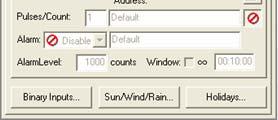
201 Pulsecounter 201


202 On switch time & On time 202

203 Daylight control This mood controls the fluorescent lights depending on the light level measured on analog input 1. With an Set command on this address you activate the daylight control. With a Clear the outputs go to 0% 203

204 Daylight control The outputs are controlled in group with a 1-10V signal. Individual control of each output is done with a relay. In this wiring diagram all outputs can be turned on/off individually, but the light level is the same for all. 204
205 THANK YOU 205
PART 1: HARDWARE. Author: Vandermeerschen M. Version
 PART 1: HARDWARE Author: Vandermeerschen M. 1 Version 1.07 L 230VAC N 2 LUXOM SEGMENT Power supply 24VDC BUS termination Push Button Feedback without extra wiring I/O Interface BUS RS232 Relay module 230VAC
Tebis application software
 Tebis application software Input products / ON / OFF output / RF dimmer Electrical / Mechanical characteristics: see product user manual Product reference Product designation TP device RF device WYC42xQ
Compatibility mode. rev. 0.1, 10/09/2015. Compatibility mode Sx tool manual 1
 Compatibility mode rev. 0.1, 10/09/2015 1 Index 1 COMPATIBILITY MODE FOR DUPLINE... 4 1.1 How to enable the Dupline compatibility in the Sx tool... 5 1.2 How to manage the Dupline network in a Sx2WEB24
Tebis application software
 Tebis application software LED projector with quicklink radio infrared detector Electrical / Mechanical characteristics: see product user manual Product reference Product designation Application software
Premium INSTALLATION AND USER GUIDE ENGLISH TAHOMA BOX. - INSTALLATION AND USER GUIDE. Rev A _01-16
 Premium INSTALLATION AND USER GUIDE ENGLISH - INSTALLATION AND USER GUIDE TAHOMA BOX Rev A _01-16 www.somfy.com TaHoma, connected homes the Somfy way! Remotely control and manage the devices in your home
Casambi App FAQ. Version Casambi Technologies Oy.
 Casambi App FAQ Version 1.3 30.9.2016 Casambi Technologies Oy 1 of 12 GENERAL 3 Q: What is Casambi app used for? 3 Q: Which mobile devices are supported? 3 Q: Where can I get the Casambi app? 3 FIRST TIME
application software
 application software application software Input products / Shutter Output / RF output Electrical / Mechanical characteristics: see product user manual Product reference Product designation TP device RF
application software
 application software application software Input products / Shutter Output / RF output Electrical / Mechanical characteristics: see product user manual Product reference Product designation TP device RF
SAPLING MASTER CLOCKS
 SAPLING MASTER CLOCKS Sapling SMA Master Clocks Sapling is proud to introduce its SMA Series Master Clock. The standard models come loaded with many helpful features including a user friendly built-in
LARGE DIGITAL LED REAL TIME CLOCKS
 LARGE DIGITAL LED REAL TIME CLOCKS ALTERNATING DATE and TEMPERATURE ( programmable ) SETS THE INDUSTRY STANDARD FOR LARGE DIGITAL CLOCKS INDOOR OR OUTDOOR USE Hours Minutes or Hours Minutes and Seconds
IP Roombox. Hotel Room Management
 Hotel Room Management Hotel solutions Versatile room management system You need a simple solution which allows you to control all the hotel room electrical applications? Hager offers you a unique combination
Casambi App User Guide
 Casambi App User Guide Version 1.5.4 2.1.2017 Casambi Technologies Oy Table of contents 1 of 28 Table of contents 1 Smart & Connected 2 Using the Casambi App 3 First time use 3 Taking luminaires into use:
Dimming actuators of the FIX series DM 4-2 T, DM 8-2 T
 Dimming actuators of the FIX series DM 4-2 T, DM 8-2 T DM 4-2 T 4940280 DM 8-2 T 4940285 Updated: Jun-16 (Subject to change) Page 1 of 70 Contents 1 FUNCTIONAL CHARACTERISTICS... 4 1.1 OPERATION... 5 2
KNX Dimmer RGBW - User Manual
 KNX Dimmer RGBW - User Manual Item No.: LC-013-004 1. Product Description With the KNX Dimmer RGBW it is possible to control of RGBW, WW-CW LED or 4 independent channels with integrated KNX BCU. Simple
User interface. Abbreviations / Meanings
 RG66012649 User interface Contents Page Abbreviations / Meanings Abbreviations / meanings... 2 Button Identification... 3 On-screen Indicators... 4 Quick Start... 5 Setting the time and day... 5 Changing
Dimming actuators GDA-4K KNX GDA-8K KNX
 Dimming actuators GDA-4K KNX GDA-8K KNX GDA-4K KNX 108394 GDA-8K KNX 108395 Updated: May-17 (Subject to changes) Page 1 of 67 Contents 1 FUNCTIONAL CHARACTERISTICS... 4 1.1 OPERATION... 5 2 TECHNICAL DATA...
Transponder Reader TR22A01KNX TR22A11KNX. Product Handbook
 Transponder Reader TR22A01KNX TR22A11KNX Product Handbook Product: Transponder Reader Order Code: TR22A01KNX - TR22A11KNX Application Program ETS: EEL_RDT1_10 Transponder Card Reader Pagina 1 di 24 Index
EVF 300 series. Controllers for electric bread and pizza ovens, with touch-keys, in split version and which can be integrated into the unit.
 EVF 300 series Controllers for electric bread and pizza ovens, with touch-keys, in split version and which can be integrated into the unit. Installer manual ENGLISH Code 144F300E114 Page 1 of 62 Important
Application Note M7L VideoPad-AV Installation Setup (software 9.1 onwards)
") Installation Guidelines The VideoPad-AV should be installed within a double UK electrical box at least 35mm deep. The electrical box must only have screw lugs fitted on the left and right sides. The VideoPad-AV
Installation Guidelines The VideoPad-AV should be installed within a double UK electrical box at least 35mm deep. The electrical box must only have screw lugs fitted on the left and right sides. The VideoPad-AV
All real signals have scale factor 10. Integer, Index and Logic has always scale factor 1.
 STRA communication The types of the signals (types in the list below): 1 = Coil Status Register ( function = 1, 5 and 15) - 0x 2 = Discrete Input ( function = 2) - 1x 3 = Holding Register ( function =
Installation and User Guide 458/CTR8 8-Channel Ballast Controller Module
 Installation and User Guide 458/CTR8 8-Channel Ballast Controller Module Helvar Data is subject to change without notice. www.helvar.com i Contents Section Page Introduction 1 Installation 2 1. Attach
Home automation to suit any budget
 Home automation to suit any budget Catalogue GUAR ANTEE YEAR DOBISS can help you bring out the best in your house What is DOBISS? DOBISS is a Belgian manufacturing company and part of the international
DX-10 tm Digital Interface User s Guide
 DX-10 tm Digital Interface User s Guide GPIO Communications Revision B Copyright Component Engineering, All Rights Reserved Table of Contents Foreword... 2 Introduction... 3 What s in the Box... 3 What
SAPLING WIRED SYSTEM
 SAPLING WIRED SYSTEM Sapling 2-Wire System DESCRIPTION The Sapling 2-Wire System is one of the most innovative and advanced wired systems in the synchronized time industry. It starts with the SMA Series
DLP200M 2 Relay Module for Heating and Cooling Plants
 Product Sheet TH6.24 Thermostat Type DLP200M DLP200M 2 Relay Module for Heating and Cooling Plants The DLP 200 M is a relay module for activation of loads (namely thermal actuators or circulators) in wireless
Agilent Technologies. N5106A PXB MIMO Receiver Tester. Error Messages. Agilent Technologies
 Agilent Technologies N5106A PXB MIMO Receiver Tester Messages Agilent Technologies Notices Agilent Technologies, Inc. 2008 2009 No part of this manual may be reproduced in any form or by any means (including
ISS Small Lecture Theatre Specification 2017
 ISS Small Lecture Theatre Specification 2017 A small Lecture Theatre would typically have the following properties Normally racked teaching space (some flat floored) Guideline size: up to 70m 2 Guideline
4.0 Description. 2-channel operation D1 and D2 rated at 200 VA each. 1-channel operation D1 rated at 400 VA (see connection chap. 6.
 _307 238_EN_LUXOR 405_310 410 01_D.qxd 21.09.16 10:54 Seite 1 Operating Manual Dimmer module 4050100 1.0 Designated use The LUXOR dimmer module expands the existing LUXOR series of devices. It switches
Quick Operation Guide of LTN7700/7600 Series NVR
 Quick Operation Guide of LTN7700/7600 Series NVR UD.6L0202B0042A02 Thank you for purchasing our product. If there is any question or request, please do not hesitate to contact dealer. This manual is applicable
NEW. Simply smart. Simply LUXOR. The LUXORliving smart home system.
 NEW Simply smart. Simply LUXOR. The LUXORliving smart home system. LUXORliving controls your building. Simply safe. The new LUXORliving smart home system. LUXORliving is the intuitive smart home system
Appendix Lightolier Compose System
 Appendix Lightolier Compose System The Lightolier Compose system has been designated a legacy feature and support is normally unavailable. Open the HCA Properties dialog and choose the legacy tab to enable
Receiver Integration Note
 ELAN Home Systems Life Just Got Better Receiver Integration Note Manufacturer: Model Number(s): Controller Core Module: Denon Document Revision Date: 1/30/2012 OVERVIEW AND SUPPORTED FEATURES AVR-1912,
DINOX&Digital&Video&Recorder&
 DINOX&Digital&Video&Recorder& & & & & & & & & & &&&Quick&Operation&Guide& UD.7L0X02B1228B01& Thank you for purchasing our product. If there is any question or request, please do not hesitate to contact
Re:connect M 203. RS232 Interface Revox. Dominating Entertainment. Revox of Switzerland. E 2.03
 of Re:connect M 203 RS232 Interface Revox Dominating Entertainment. Revox of Switzerland. E 2.03 Attention! After updating the firmware to version 2.00 or higher, we recommend completely resetting the
S-Series Server Setup Quiz
 1. In the System Setup window, System Information displays additional information such as: (a) IP Address (b) Modems (c) Sound Card (d) Video Channels and Audio Channels 2. You can change the Recording
Sensor module. Safety instructions. Function Correct use. Product characteristics. Structure of the device. Operation. Ref.No.
 Sensor module Ref.No.: SM 1608 V03 Safety instructions Caution! Electrical devices may only be installed and fitted by electrically skilled persons. Non-compliance with the installation information could
Digital Video Recorder
 Digital Video Recorder Quick Operation Guide UD.6L0202B0067A02 Thank you for purchasing our product. If there is any question or request, please do not hesitate to contact dealer. This manual is applicable
STX Stairs lighting controller.
 Stairs lighting controller STX-1795 The STX-1795 controller serves for a dynamic control of the lighting of stairs. The lighting is switched on for consecutive steps, upwards or downwards, depending on
K-BUS Dimmer Module User manual-ver. 1
 K-BUS Dimmer Module User manual-ver. 1 KA/D0103.1 KA/D0203.1 KA/D0403.1 Content 1. Introduction... 3 2. Technical Parameter... 3 3. Dimension and Connection Diagram... 4 3.1 KA/D0103.1... 4 3.2 KA/D0203.1...
A Motor can be in many groups, by assigning additional channel# on it.
 Timer Remote Control Instruction How to use the channel numbers - There are 32 channels on the Remote Control Timer you can assign to Curtain Motor(s). To operate the Motors individually by itself only,
DLP600M 6+1 Relay Module for Heating and Cooling Plants
 Product Sheet TH6.25 Thermostat Type DLP600M DLP600M 6+1 Relay Module for Heating and Cooling Plants The DLP 600 M is a relay module for activation of loads (namely thermal actuators or circulators) in
CI-218 / CI-303 / CI430
 CI-218 / CI-303 / CI430 Network Camera User Manual English AREC Inc. All Rights Reserved 2017. l www.arec.com All information contained in this document is Proprietary Table of Contents 1. Overview 1.1
Owner's Manual. TOUCH SCREEN CONTROLLER for Air Conditioning Control System. Model BMS-CT5120UL. English
 TOUCH SCREEN CONTROLLER for Air Conditioning Control System Model BMS-CT5120UL English Contents 1 Precautions for safety.................................................. 5 2 Main functions........................................................
NX-series User Manual
 NX-series User Manual http://www.iviewtech.com 1 CONTENT INDEX 1 NX-SERIES OVERVIEW... 4 1.1. NX-Series Features 4 1.2. NVR CONTROL PANEL 5 1.3. NVR BACK PANEL 5 2 GETTING STARTED... 8 3 LIVE VIEW... 10
SINGLE ZONE CLIMATE ZONING SYSTEM. Technical Manual. Polyaire Pty Ltd
 SINGLE ZONE CLIMATE ZONING SYSTEM Technical Manual Polyaire Pty Ltd 11-13 White Road GEPPS CROSS South Australia, 5094 Tel: (08) 8349 8466 Fax: (08) 8349 8446 www.polyaire.com.au CONTENTS Features 1 Application
Tri-level Control HF Sensor
 Daylight Monitoring TM Ambient daylight threshold oop in oop out Tri-level Control HF Sensor HC403VRC-KD HC404VRC-KD Detached Version with Daylight Monitoring and Remote Control Applications Occupancy
LED DRIVERS. LQC4D-V1 4 channels. User Manual FEATURES
 pag. 1/13 FEATURES Outputs: 4 x channels BUS+SEQUENCER+FADER+DIMMER+DRIVER Input: DC 12/24/48 Vdc BUS Command: DALI LOCAL Command: 4x N.O. push button (with or without memory), 0-10V, 1-10V Controls: dimmer,
Environmental Conditions, page 2-1 Site-Specific Conditions, page 2-3 Physical Interfaces (I/O Ports), page 2-4 Internal LEDs, page 2-8
, page 2-4 Internal LEDs, page 2-8") 2 CHAPTER Revised November 24, 2010 Environmental Conditions, page 2-1 Site-Specific Conditions, page 2-3 Physical Interfaces (I/O Ports), page 2-4 Internal LEDs, page 2-8 DMP 4305G DMP 4310G DMP 4400G
2 CHAPTER Revised November 24, 2010 Environmental Conditions, page 2-1 Site-Specific Conditions, page 2-3 Physical Interfaces (I/O Ports), page 2-4 Internal LEDs, page 2-8 DMP 4305G DMP 4310G DMP 4400G
CCE900-IP-TR. User s Guide
 CCE900-IP-TR CCE900-IP-T & CCE900-IP-R User s Guide i-tech Company LLC TOLL FREE: (888) 483-2418 EMAIL: info@itechlcd.com WEB: www.itechlcd.com 1. Introduction The CCE900-IP-T & CCE900-IP-R is a solution
Simply clever! The digital DIN-rail time switches by Grässlin
 Simply clever! The digital DIN-rail time switches by Grässlin talento pro Trends and developments on the market. Maximum energy efficiency at low efforts In a saturated fast-moving market, the trend towards
DiD. LCD Video Monitor & Video Wall Universal User Manual. Digital Information Display
 LCD Video Monitor & Video Wall Universal User Manual DiD Digital Information Display Video Monitor Models M82S1/M70S1/M65S1/M55S1/M46S1/M40S1/M32S1/M24S1/M19S2/M19S1 Video Wall Models PD55N3/PD46N4/PD46N3/PD46N2/PD40N2
Instruction manual. DALI Gateway art Installation manual
 Instruction manual DALI Gateway art. 01544 Installation manual Contents GENERAL FEATURES AND FUNCTIONALITY from page 5 ETS PARAMETERS AND COMMUNICATION OBJECTS from page 6 COMMUNICATION OBJECTS GENERAL
Integration Note. Manufacturer: OVERVIEW AND SUPPORTED FEATURES
 Manufacturer: Model Number(s): Minimum Core Module Version: Document Revision Date: Denon Integration Note AVR-2805, 3805, 1613, 1713, 1912CI, 1913, 2112CI, 2113CI, 2310CI, 2311CI, 2312CI, 2313CI, 2808CI,
ORM0022 EHPC210 Universal Controller Operation Manual Revision 1. EHPC210 Universal Controller. Operation Manual
 ORM0022 EHPC210 Universal Controller Operation Manual Revision 1 EHPC210 Universal Controller Operation Manual Associated Documentation... 4 Electrical Interface... 4 Power Supply... 4 Solenoid Outputs...
Part 1 Basic Operation
 This product is a designed for video surveillance video encode and record, it include H.264 video Compression, large HDD storage, network, embedded Linux operate system and other advanced electronic technology,
LUMINOUS TWO APP USER GUIDE FOR ANDROID
 LUMINOUS TWO APP USER GUIDE FOR ANDROID Disclaimer Please note that the images and instructions contained in this guide are based on app version 2.2.3. While the information is accurate to this app version,
Ingenium s KNX commitment
 EN Ingenium s KNX commitment Ingenium HQ in Asturias, Spain. BES, Ingenium s KNX commitment Bes, the Ingenium s emergent KNX product line, reaches the international market to stay. With versatile and
Any feature not specifically noted as supported is not supported.
 Manufacturer: ELAN Integration Note Model Number(s): EL-4KM-VW44 (Device Ver 2.20; Web Module Ver 6.23) Minimum Core Module Version: Document Revision Date: 8.1.395 5/11/2017 OVERVIEW AND SUPPORTED FEATURES
GreenParking. Commissioning guide. GreenParking
 GreenParking GreenParking Page Table of Contents Introduction....4. GreenParking...4. Working principle...4.3 Intended use...4.4 About this commissioning guide...4.5 Warnings.............................................................
ENGR 1000, Introduction to Engineering Design
 Unit 2: Mechatronics ENGR 1000, Introduction to Engineering Design Lesson 2.3: Controlling Independent Systems Hardware: 12 VDC power supply Several lengths of wire NI-USB 6008 Device with USB cable Digital
B. The specified product shall be manufactured by a firm whose quality system is in compliance with the I.S./ISO 9001/EN 29001, QUALITY SYSTEM.
 VideoJet 8000 8-Channel, MPEG-2 Encoder ARCHITECTURAL AND ENGINEERING SPECIFICATION Section 282313 Closed Circuit Video Surveillance Systems PART 2 PRODUCTS 2.01 MANUFACTURER A. Bosch Security Systems
Ocean Sensor Systems, Inc. Wave Staff, OSSI F, Water Level Sensor With 0-5V, RS232 & Alarm Outputs, 1 to 20 Meter Staff
 Ocean Sensor Systems, Inc. Wave Staff, OSSI-010-002F, Water Level Sensor With 0-5V, RS232 & Alarm Outputs, 1 to 20 Meter Staff General Description The OSSI-010-002E Wave Staff is a water level sensor that
Package Contents. LED Protocols Supported. Safety Information. Physical Dimensions
 Pixel Triton Table of Contents Package Contents... 1 Safety Information... 1 LED Protocols Supported... 1 Physical Dimensions... 1 Software Features... 2 LED Status... 2 Power... 2 Activity LED... 2 Link
ControLIT : Lighting Control Setup Manual for PRISM Smart LED RGBW Retrofit Downlight
 ControLIT : Lighting Control Setup Manual for PRISM Smart LED RGBW Retrofit Downlight Manual for iphone and ipad Users (System Requirements: ios 8.0+) TABLE OF CONTENTS 1. Overview 2 2. Getting Started
CULT. Connection diagram. PC Installer application. 1. General principle. 2. Overview. CULT: PC Installer application EN1.5
 1. General principle P Installer application This application allows the installer to configure all ult video modules. The user gets the opportunity to assign a name to external cameras, switches, Fasttel
Ocean Sensor Systems, Inc. Wave Staff III, OSSI With 0-5V & RS232 Output and A Self Grounding Coaxial Staff
 Ocean Sensor Systems, Inc. Wave Staff III, OSSI-010-008 With 0-5V & RS232 Output and A Self Grounding Coaxial Staff General Description The OSSI-010-008 Wave Staff III is a water level sensor that combines
HS-509 VIBRATION TRIP MODULE
 HS-509 VIBRATION TRIP MODULE 1. Overview The HS-509 is a configurable trip amplifier capable of accepting a 4-20mA signal from a HS-420 sensor and providing two trip action relay outputs along with an
GFT channel Time Interval Meter
 Key Features Five-channel Time-Interval Meter: One Start and four Stops - 13 picosecond resolution - < 50 picosecond RMS jitter - > 100 second range - 10 MHz sample rate per channel Common GATE input Input
A new generation of access control.
 TM A new generation of access control. 2 or 4 Door Expandable Controller INSTALLATION MANUAL Installation overview: Installation Diagram Switch Alpha 4 Alpha 4 + PoE Alpha 4 + PoE Alarm central Accessory
QUICK START GUIDE FLEXSLICE MODULES
 TECHNOLOGY POWER ETHERCAT OUT ETHERCAT IN STATUS LED S POWER AND I/O STATUS LED S USER TAB EBUS CONNECTOR LOCK QUICK START GUIDE FLEXSLICE MODULES P366 P371 P372 P375 P376 P377 P378 P379 description The
DS-7200HVI/HFI-SH Series DVR Quick Operation Guide
 DS-7200HVI/HFI-SH Series DVR Quick Operation Guide UD.6L0202B0019A01 Thank you for purchasing our product. If there is any question or request, please do not hesitate to contact dealer. This manual is
Projector Management Application Version 7.00 Instruction Guide
 Projector Management Application Version 7.00 Instruction Guide Contents 1 INTRODUCTION... 4 1.1 OUTLINE... 4 1.2 SYSTEM... 4 2 INSTALLATION... 5 2.1 SYSTEM REQUIREMENTS... 5 2.2 PROJECTOR MANAGEMENT APPLICATION
Flip-Flops. Because of this the state of the latch may keep changing in circuits with feedback as long as the clock pulse remains active.
 Flip-Flops Objectives The objectives of this lesson are to study: 1. Latches versus Flip-Flops 2. Master-Slave Flip-Flops 3. Timing Analysis of Master-Slave Flip-Flops 4. Different Types of Master-Slave
EdgeConnect Module Quick Start Guide ITERIS INNOVATION FOR BETTER MOBILITY
 EdgeConnect Module Quick Start Guide ITERIS INNOVATION FOR BETTER MOBILITY 493456301 Rev B April 2009 Table of Contents Installation... 1 Setup... 2 Operation... 4 Live Video... 4 Video Settings... 5 Network
Hotel Ballroom. Figure 1 above, graphically details this scenario. 8:1 1 of 5. We ve got it under control
 In this application we have a Ballroom for a typical 5 Star Hotel. The Ballroom is complete with a Prefunction area and has two de-mountable partitions in the main area. These partitions may be closed
Innovative Air Systems ABN When Calling For Support Quote:.doc
 1.0 User Guide 1.1 Normal Display This displays the current time and date. 1.2 Condition On Press the button to turn on the air conditioning. If the After Hours Timer is set then the air conditioning
RGB LED Controller and Dimmer Pro Plus RF Remote 3-Channels, 12 or 24 VDC Part No. RGB-3-Dimmer-Pro
 11235 West Bernardo Court, Suite 102 San Diego, CA 92127 888-880-1880 Fax: 707-281-0567 EnvironmentalLights.com RGB LED Controller and Dimmer Pro Plus RF Remote 3-Channels, 12 or 24 VDC Part No. RGB-3-Dimmer-Pro
MODEL HA07 - MASTER CONTROLLER INSTRUCTIONS
 Thank you for purchasing Intermatic s Home Settings devices. With these products you can reliably and remotely control lighting and appliances. The outstanding features of the Home Settings program include:
(BM4 x12 6PCS) Power Cable. User Guide
 Power Cable. User Guide") 85 T2 SMART TV 58 (BM4 x12 6PCS) Power Cable User Guide The parts (BM4 x12 6PCS) Installation Place the TV face down on a soft and flat surface (blanket, foam, cloth, etc.) to prevent any damage to the
85 T2 SMART TV 58 (BM4 x12 6PCS) Power Cable User Guide The parts (BM4 x12 6PCS) Installation Place the TV face down on a soft and flat surface (blanket, foam, cloth, etc.) to prevent any damage to the
STR 2000 Series Transceiver Programming Manual (V2) Table of Contents
 Table of Contents") Note: Press both buttons together simultaneously to enter programming mode. PROGRAMMING THE DATE Table of Contents Programming the Date.. Page 2 TECHNICAL MODE Technical Mode..... Pages 2-3 PROGRAMMABLE
Note: Press both buttons together simultaneously to enter programming mode. PROGRAMMING THE DATE Table of Contents Programming the Date.. Page 2 TECHNICAL MODE Technical Mode..... Pages 2-3 PROGRAMMABLE
FOREST SHUTTLE S / L / M RECEIVER
 2 FOREST SHUTTLE S / L / M RECEIVER QUICK INSTALLATION OF ASSEMBLED TRACKS : Programming Shuttle S / L / M Receiver to a channel One pre-assembled motorized curtain track systems is standard programmed
M203 LG. Multiroom Planer V2.00. Introduction. New features from software V2.00
 of M203 LG D 2.06 Attention! After updating the M203 firmware to version 2.00 or higher, we recommend completely resetting the M203 interface by pressing the Disable softkey on setup page #2 for several
2000 W, 2450 MHz Microwave Generator GMP 20K SM 56M230 FST 3 IR
 2000 W, 2450 MHz Microwave Generator GMP 20K SM 56M230 FST 3 IR Power supply It is based upon the latest switch mode power supply technology, offering size reduction (i.e. 19 rack, 3U power supply), good
of Loewe E 2.10_m1 1
 of Loewe E 2.10_m1 1 Attention! After updating the M203 firmware to version 2.00 or higher, we recommend completely resetting the M203 interface by pressing the Disable softkey on setup page #2 for several
Getting started with
 Getting started with Electricity consumption monitoring single phase for homes and some smaller light commercial premises OVERVIEW: The OWL Intuition-e electricity monitoring system comprises of three
AES-402 Automatic Digital Audio Switcher/DA/Digital to Analog Converter
 Broadcast Devices, Inc. AES-402 Automatic Digital Audio Switcher/DA/Digital to Analog Converter Technical Reference Manual Broadcast Devices, Inc. Tel. (914) 737-5032 Fax. (914) 736-6916 World Wide Web:
PS600 Digital Visualizer. User Manual. English - 0
 PS600 Digital Visualizer User Manual English - 0 Table of Content COPYRIGHT INFORMATION... 3 CHAPTER 1 PRECAUTIONS... 4 SAFETY PRECAUTIONS... 5 FCC WARNING... 5 EN55022 (CE RADIATION) WARNING... 5 CHAPTER
DDW36C Advanced Wireless Gateway - Safety and Installation Product Insert. Federal Communications Commission (FCC) Interference Statement
 Interference Statement") DDW36C Advanced Wireless Gateway - Safety and Installation Product Insert Federal Communications Commission (FCC) Interference Statement This equipment has been tested and found to comply with the limits
DDW36C Advanced Wireless Gateway - Safety and Installation Product Insert Federal Communications Commission (FCC) Interference Statement This equipment has been tested and found to comply with the limits
Click Here To Start Demo
 Click Here To Start Demo AirLogix Demo Title Screen AirLogix Interactive Demonstrator Version 3.0 Copyright 2005 by Case Engineering inc This is intended as a working active demonstration only. Every attempt
Aspect 2 Circuit Digital Scene Control
 Aspect 2 Circuit Digital Scene Control S p e c i f i c a t i o n 2 circuits of trailing edge dimming 500W total between the two circuits Both circuits feature independent overload, short-circuit and open-circuit
Digital Clock with Second Circle DA Series
 Digital Clock with Second Circle DA Series State of art technology digital clock intended to be used indoors the clock will find use in many applications, in radio or television studios or as wall clock
Overview. Shipped in the Venue Vizion Package: Simplified Integration Process. Installation consists of 6 easy steps:
 Overview Shipped in the Venue Vizion Package: Four two-channel QMOD Encoder-Modulators Each unit can accept up to 2 inputs, providing up to 8 channels in the system. One ICE-HE-DXL Display Control Center
OPERATIONAL MANUAL EMZS CH Speaker Zone Selector. Version 1.6
 OPERATIONAL MANUAL EMZS-8012 12CH Speaker Zone Selector Version 1.6 1 Product Overview The EMZS-8012 is a 1U rack-mounting unit, provide 12 channel direct zone switching for single source public address
USCG Exam questions related to PLCs by Frank Owen, Maine Maritime Academy, 23 October 2018
 USCG Exam questions related to PLCs by Frank Owen, Maine Maritime Academy, 23 October 2018 Timers The USCG questions reference three different types of timers: 1. On-delay timer (TON) 2. Off-delay timer
Luminaire installation box Surface-mounted box Ceiling installation box
 -Smart PTM Ambient light sensor and motion detector for constant lighting control uminaire installation box Surface-mounted box Ceiling installation box Overview: -SMART PTM i is an ambient light sensor,
KNX / EIB Product Documentation. DALI Gateway. Date of issue: Order no Page 1 of 136
 KNX / EIB Product Documentation DALI Gateway Date of issue: 13.03.2008 64540122.12 Order no. 7571 00 03 Page 1 of 136 KNX / EIB Product Documentation Table of Contents 1 Product definition... 3 1.1 Product
LinTronic. Beo5/Beo6. Updated:
 LinTronic Beo5/Beo6 http://lintronic.dk Updated: 110522 Date Revised 110410 CONFIGURATOR SQL added/updated 100122 Some words of advise 090920 New Configurator 090614 YouTube video added. 090612 RELAY 208
XTM72E & F Real-Time Clock Modules
 Capricorn Controls Ltd Data & Application Notes Page 1 of 8 XTM72E & F Real-Time Clock Modules Originally designed to compliment our wide range of Gen-Set controls, these DC powered Real-Time-Clocks have
1x12 VGA & Audio over CAT5 Splitter
 SP-9112 1x12 VGA & Audio over CAT5 Splitter User Manual rev: 160322 Made in Taiwan Safety and Notice The SP-9112 1x12 VGA & Audio over CAT5 Splitter has been tested for conformance to safety regulations
SQTR-2M ADS-B Squitter Generator
 SQTR-2M ADS-B Squitter Generator Operators Manual REVISION A B C D E F G H J K L M N P R S T U V W X Y Z December 2011 KLJ Instruments 15385 S. 169 Highway Olathe, KS 66062 www.kljinstruments.com NOTICE: