USCG Exam questions related to PLCs by Frank Owen, Maine Maritime Academy, 23 October 2018
|
|
|
- Barnard Hodges
- 5 years ago
- Views:
Transcription

1 USCG Exam questions related to PLCs by Frank Owen, Maine Maritime Academy, 23 October 2018
2
3
4
5 Timers The USCG questions reference three different types of timers: 1. On-delay timer (TON) 2. Off-delay timer (TOF) 3. Pulse timer (TP) Let s look at how these are defined in a reference book on the exam. We did not study a pulse timer in ET401 (so far). These timers are not standard timers. What we learned about were more standard than these. But you must learn these definitions to be able to answer these questions correctly. None of the timers shows Preset and Accum, as we studied. USCG-TON Obviously the Input is our TGR (trigger). When TRG goes high, USCG-TON starts counting up. The Timer Output is what we ve called DN (done). But different from the standard TON, the timer keeps timing even if TGR goes low. There is no
6 information on how to reset the timer. Perhaps there is a separate reset input. What characterizes USCG-TON is that one turns the Input on, but it is only after some delay (the elapsed time), that the Timer Output goes high. USCG-TOFF Like a standard TOF, the counting starts when Input goes low. The Timer Output is a standard TOF s DN and TT ORed together: DN TT ( stands for OR; && stands for AND). USCG-TOFF s Timer Output goes high when Input goes high, but it stays high also when Input goes low and starts the timing. It remains high while the timing is in progress and only goes low when the timing has stopped. Again, there is no information on how to reset the timer. What characterizes USCG-TOFF is that one turns the Input off, but it is only after some delay that the Timer Output goes low. USCG-PT The pulse timer is characterized by the fact that the Timer Output goes high when Input goes high, but then it automatically goes low after the elapsed time is over. So this Timer Output turns on, then off after a prescribed period (the length of the pulse).
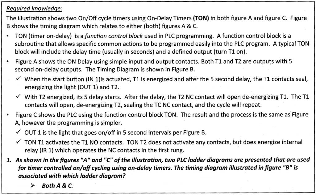
7 Figure A: The output coils represent two TONs. But when energized, TI and T2 do not turn on until after their delay is exhausted. For an example, assume In1 is a retentive start switch. Assume both timers have 5-second delays. When we start, T2 is low. So when the In1 is switched on, T1 starts counting. After 5 seconds, T1 goes high. This initiates the timing cycle of T2. After 5 seconds, T2 goes high. This opens the break in the first rung, resetting T1 i.e. making it go low. This also resets T2 i.e. making it go low. This closes the break on the first rung, and the cycle starts over again. Out1 is simply an indicator light that shows when T1 is high. Thus this light would be on only when T2 is counting, not as shown. T1 stays high only when T2 is counting. It goes out once T2 is finished counting and it s been reset. That is, only when T1 is counting and has not produced a high output yet will the light be off. This is a bit confusing, but in the diagram, the 5-second blocks where T1 and Out1 are high are the very periods after T1 s timing has been done and T2 is actively timing. The diagram in C is simply a different way to write the ladder logic in A. It does not, however, include Out1 as an output. In terms of standard TONs, T1 and T2 are the DNs for the two timers. The indication that the two timers are TONs and not TOFs is given in the question, not in the figure. An explanation from a study guide is given below.
8
9 If we assume that Figure B goes with Figure A, the momentary input In1 turns the TON on. The input is latched on by Out1, which is an indicator that the timer is actively timing, like the standard TON s TT variable. Once the timing completed, Timer goes high. But the break, identified by TON timer, resets the timer. Why Timer stays high after that is not clear. But, if we look at Figure B, we see that an input went high, and then after a period the output went high. So just looking at Figure B, what is represented here is a TON. Figure D shows In1 going high, which sets Out1 high for a certain period of time. Then when the timing is finished, Out1 goes low. Thus Figure D represents a pulse timer output. If Figure D goes with the ladder diagram in Figure C, the input is a retentive switch (In1 goes on and stays on). This starts the timer. Timer is the timer output, so it remains off until the time has elapsed. Out1 seems to be like a standard TON s TT output. It goes high and stays high as long as the timing is active. The ladder in Figure E seems to perform the same function as the ladder in Figure C. The Timer output is the internal relay, which is off until the timing is finished. So Out1 will be high during the timing. When the timing is done, the internal relay goes high, which makes Out1 turn off. Thus, this timer generates a pulse.
.")
10 I disagree with the first conclusion. You push a button and then, after a delay, the timer output goes high (Timer). So for 1 we have, instead, an On-delay timer.

11 The top figure is a sort of Function-Block Diagram, another way to represent ON/OFF logic. It is interesting to develop the truth table for it. When you do, you will see that this represents an XOR function. Note that the Output is high only when one of the inputs is high and the other is low. The relationship between this FBD and the ladder in Figure B is quite close too. Regarding the ladder at lower left, obviously we have Lamp1 on whenever SW-0 is on and Lamp2 on only when both switches are closed. The time sequence at right is an illustration of this. Function-block diagrams The representation of the function block shown above in EL-0231 Figure A is not standard. Here is a little about them, because you are liable to run across them in automation work in industry. Below is how a function block is normally represented: The flow is from left to right. The two lines on the left are inputs. OUT is the function block s output, determined in some way by the input. The little title at the top indicates what type of function the block performs. An example makes this clearer.

12 This is the standard representation for the XOR function shown at the very top of EL-0231 Figure A. Note that there are no NOT blocks here. Negation is indicated by the little circle on the inputs to the AND blocks at left. Thus, going into IN1 of the top AND block is NOT A. Negation can also be indicated on an output, as shown below. This block is AND, but negated. So it performs the NAND function. There is also an assignment block: What this block does is store the input somewhere in memory. That memory location is specified when the block is set up. But the block does not change the value of the input, so OUT has the same value as IN1 and can be used further downstream. IN1 may contain either a digital value (0/1) or an analog value. If IN1 is an analog value, then its sign is flipped. For the case of a digital input, the assignment block allows us to create a NOT block: The first two blocks negate the input in one way or another, but they are subtly different. (a) does negate the input, stores that negation, then passes it on to the output. (b) does not negate the input, in fact stores it in the designated memory location, but it passes the negation of the input on downstream. (c) is actually a negation block (NOT). Often in computer programming the not function is indicated by <>. Set/Reset blocks: There are two of these blocks SR (set/reset) and RS (reset/set). These are somewhat different blocks from those already covered. They are designed to latch current values, unless other conditions require a change. The blocks are similar to how they function. With both blocks, for example

13 SET, if high, attempts to set OUT high RESET, if high, attempts to set OUT low maintain OUT at its previous value if neither input is high. This is the latching function. With SR, if SET is high, it blocks RESET. SET high always sets OUT high, regardless of the value of RESET. You might say that SET overrides RESET in an SR block. RS behaves much like SR, but here RESET has priority. SET cannot override RESET. In fact, SET is disabled if RESET is high. SET is only effective if RESET is low. RS has the same maintain feature of SR: if both inputs are low, OUT stays right where it was on the last scan. Examples of using SR and RS are shown below. Function-block timers are shown below. We have studied these timers, and they function as previously described. All three have the same two inputs and outputs. IN is the timer trigger. PT is the Preset time. ET is the elapsed time (Accum). Q is the timer output (DN on a ladder timer). Thus for the TON, the input is triggered on, the timing starts, and Q goes high after PT is finished. TOF is triggered by IN going low. A period of time elapses, and then Q (initially high) goes low. TP produces a pulse. Q goes high for the designated time, then goes low. Thus there is really nothing new here, just the format. There are, of course, function-block counters too: The up counter and down counter count when CU and CD are pulsed. CV is the counter value. The CTU starts counting at 0 and counts up to PV, the preset value. When CV PV, Q goes high. When R is pulsed on the CTU, CV is set once again to 0. The CTD works similarly. But this counter starts with CV = PV and counts down, once for each pulse of CD. When CV reaches 0 or falls below it, Q goes high. The CTU and the CTD only count one way. The up/down counter, CTUD, counts both ways. If CU is pulsed, CV increases by 1. If CD is pulsed, CV decreases by 1. QU goes high if CV PV. QD goes high if CV falls to 0 or below. This counter has two resets. If RU is pulsed, CV is set to 0. If RD is pulsed, CV is set to PV. Example: Motor latch circuit

14 Below are shown two motor-start latching FBDs. The MTR is started by pressing a momentary NO pushbutton. It is stopped by pushing a NO push button. The FBD on the left used an SR block; the FBD on the right uses a RS block. Let s explore the differences between how these two FBDs function. With both, if the STP button is not pushed, when the STRT button is pressed, the motor starts. With the SR block, OUT is always set high when SET is pushed, regardless of the value of RESET. With the RS block, OUT is set high when STRT is pushed, but only if RESET is low. Thus, if STP is not pushed, so RESET is not active, in both cases the OUTPUT goes high. Also, in both cases, if STRT is not held high and STP is pressed, then OUT will be set low. In the case of SR, RESET works, but only if STRT is not high. In the case of RS, RESET going high sets OUT low, regardless of the state of SET. In both cases, OUT retains its previous value if both SET and RESET are low; so in both cases STRT will be latched so long as STP is not pressed. Thus, the only difference between the functioning of these two FBDs is in the case of both buttons being pushed simultaneously. For safety s sake, the STP button should disable the starting; i.e. STP should have priority over STRT. So the choice of RS to start and latch the pump is best. Example: Motor start with indicator lights Add RED and GRN lights to the FBD above with RS to indicate not running (RED) and running (GRN). The GRN light is directly connected to the MTR; when the MTR is on, GRN is on. The little circle before RED flips the 0 to 1 to make RED illuminate. If MTR is low, RED receives a high command because of the inversion. Example: Motor start with lock-out Take the above example and add a lock-out (LKOUT). For some reason, not specified, MTR can be locked out from starting. Modify the above FBD for this case, with LKOUT as an input. Also, if LKOUT is active, a YLW light comes on. The command from RS to start the motor only is valid if the motor is not locked-out. Thus LKOUT high means the motor is locked out. So if LKOUT is low, the AND block allows the start signal from RS to go through and start the motor. If LKOUT is high, the inverter before IN2 in the AND block flips the high signal to low. With one low signal, the AND block outputs 0, so MTR doesn t start. Example: Motor start after a delay
15 Start the motor, like above, but with a 10-second delay. During the wait phase, let a YLW light be illuminated and the RED light go off. Obviously for this we need a 10-second timer. Easiest is a TON. The key here is that if the timer has been started but is not yet finished, then IN2 of the XOR will be high, and IN1 will still be low. This means turn the YLW light on. Another thing you can add, if you wish, is to keep the RED light out if YLW is lit. Example: Motor start locked out after a specified number of starts Make a motor-start FBD like above, but let the motor start only 10 times before it is locked out. After 10 starts, some type of other operation/inspection needs to be performed before the motor can be started again. Use the variable names above. Add another input, RST, a button that resets the system after 10 starts. If the motor is locked out, illuminate a YLW light to indicate this. Obviously here we need a counter. Use a CTU unless there is a compelling reason to use CTD or CTUD. For the STRT command to get through to MTR, the output (Q) of the counter must be low. If it is high, the STRT signal does not make it through the AND because Q is negated at the input IN2 of the AND block. Only after RST is pushed does Q go back to low, thus allowing the passage of RS s OUT to MTR. Example: Pump start We want to start a pump. But certain conditions have to exist prior to starting the pump. Liquid has to be present at the pump suction before allowing the pump to start. If a command to stop the pump is issued, the pump will stop or it will disable the start. And the pump start can t have been locked out. If the pump is ever locked out, the locked-out
 and also to determine whether for the next cycle of the controller, the pump should be locked out or not.")
16 state must be cleared before the pump can be started again. The decision-making surrounding a pump start is to set the pump state (OFF or ON) and also to determine whether for the next cycle of the controller, the pump should be locked out or not. If the pump is to be started, it is only started after a 2-minute delay. What could cause the pump to be locked out from starting? If a command to stop the pump has been issued, then the pump is locked out from starting until that lock-out is reset. We start off simple. If we have a legitimate Start command and the pump is not LockedOut, then we set PumpRun high. Here LockedOut is an output to be determined by other conditions, but it will also be used as an input to determine whether to allow the pump to run. Recall from the problem statement, that if a legitimate PumpRun command is issued, the pump does not start for 2 minutes. Thus we need a TON too. But the pump is not to start unless there is liquid present. Thus the output of the TON needs to check this condition before the pump is started. Here we ve also moved PumpRun downstream, after the decision about the liquid being present is made. Now, if the pump has been locked out (by pushing the Stop button), it is to remain locked out until the lock-out has been reset. Until this is done, then the pump remains locked out. Thus, here we need to use an SR block. The pump lock-out can only be set if there is no command to start the pump. Thus the SR block would be

17 The SR block works as follows. If the pump has been locked out, the SR block will keep that state maintained (1 on the OUT of the SR block). The SR block will only allow OUT to be set low if SET is also low, i.e. there is no command to start the pump. Still to be added to the FBD is the Stop command. When it is given (stop button is pushed), the pump stops (PumpRun should go low), and the pump should be locked out (LockedOut goes high). An SR block is a retentive block. So we should use one on the left side of the FBD with Start feeding SET. Then as long as the block is not reset, the output will stay high. If the stop button is hit, OUT is set low. This happen also if Start goes high simultaneously. I.e., Stop takes priority of Start. Thus, maybe we need an RS block instead of a SR block.

18

19 This is a bad question. As we have learned, make instructions can go with either NO or NC pushbuttons. Often NO is confused with make and NC is confused with break. This goes back to the days of relay-logic ladder diagrams. So if we assume that this is the mistake made, then Input A stands for a normally open, momentary contact switch. I selected this an confirmed it on the USCG website.

20

21 The power supply s two lights show that there is AC power, from which the DC power is produced. The AC power is 120/240 VAC, while the DC power is conventionally 24 VDC. The Processor Module is the PLC itself. The Run, Scan, Fault lights are: Run means that the PLC is in run mode, i.e. actively scanning the ladder program in it. Scan, not sure what that means. My PLC has a Stop button, which means that the program scanning is suspended and the PLC is in stand-by mode. Fault, when lit, indicates that some software fault has been detected by the processor. The DC and AC inputs and outputs are all digital inputs and outputs. The digital DC I/O senses or actuates DC devices while the digital AC I/O senses or actuates AC devices. Often the analog inputs and outputs use 4-20 ma signals. So, for instance, to position a valve at 50%, a signal of 12 ma would be sent out to the valve positioner. Current loops are used because the current is the same throughout the loop, while a voltage signal experiences losses in transmission. Also the 4 ma as a minimum signal is a built-in fault detector. If there is a break in the circuit, the current goes to 0 to signal that break.
22 Temperature switch have the little zig-zag symbol attached to the switch shown in 8 and 9 above. Thus the NC thermostat is #8. When the temperature rises above a certain level, the switch opens. It would be interesting to know what all these symbols mean. At the top, the pictures, A is a limit switch. You can see the little lever with the wheel on it that something runs along until a protrusion causes the switch to be actuated. Whether it is normally open or normally closed is unclear. Often this is determined by how the switch is wired. There will be three contacts on it, so that one could wire it as normally open or normally closed. In B is shown a proximity switch, I believe. They look like that. C seems to be a pressure switch, since a fluid fitting can be seen on its face. D is, I believe, a temperature switch, judging just from its appearance. E is an electrically actuated valve. F is a float switch. The float on the end of a lever is evident.

23 Homework problems: 1. Write the truth tables and ladder-logic diagrams for these functions: OR, AND, XOR, NOR, NAND, NXOR. Do not use anything but makes and breaks for each operation (i.e. don t create NAND and NXOR simply by negating AND and XOR). 2. Use our standard TON and TOF to emulate the USCG-TON, USCG-TOF, USCG-TP timers. 3. Create the truth table for the temperature controller shown below. 4. Identify all of the items in the graphic below. 5. Using the information and examples shown for timers, how can you initiate and complete timing with a standard TON using a NOPB? Draw the ladder to do this below. A standard TON has as outputs DN and TT. 6. Write a ladder diagram to make a standard TON behave like a USCG-TON. The difference is that an output will remain high, even when the timer trigger (TGR) goes low.
 should in the ladder should behave as in the time sequence given below. 8.")

24 7. Write a ladder diagram to make a standard TOF behave like a USCG-TOF. The TOF (TGR/DN/TT) should in the ladder should behave as in the time sequence given below. 8. From the figure below develop the truth table and FBD for this case. 9. Take the example shown below. Replace the ANDs with ORs and the OR with AND. Work out the truth table and ladder logic for that configuration. Also answer the question: What type of logical function is this? 10. Work out the truth tables for the SR and the RS blocks. You will need a column OUT-PREV also to determine the results for OUT.
Exercise 4-2. Counting of Actuator Cycles EXERCISE OBJECTIVE & & &
 Exercise 4-2 EXERCISE OBJECTIVE To describe the operation of an electrical counter; To assemble and test a continuous reciprocation system; To extend and retract a cylinder a definite number of times using
INDIAN INSTITUTE OF TECHNOLOGY KHARAGPUR NPTEL ONLINE CERTIFICATION COURSE. On Industrial Automation and Control
 INDIAN INSTITUTE OF TECHNOLOGY KHARAGPUR NPTEL ONLINE CERTIFICATION COURSE On Industrial Automation and Control By Prof. S. Mukhopadhyay Department of Electrical Engineering IIT Kharagpur Topic Lecture
Factory configured macros for the user logic
 Factory configured macros for the user logic Document ID: VERSION 1.0 Budapest, November 2011. User s manual version information Version Date Modification Compiled by Version 1.0 11.11.2011. First edition
Sequential Circuits: Latches & Flip-Flops
 Sequential Circuits: Latches & Flip-Flops Overview Storage Elements Latches SR, JK, D, and T Characteristic Tables, Characteristic Equations, Eecution Tables, and State Diagrams Standard Symbols Flip-Flops
Ch 6 Basic Memory Circuits 1
 Chapter 6 Basic Memory Circuits Developing the Memory Circuit We will look first at a very simple system. Later, this type of design can be used to discuss circuits capable of controlling more complex
D Latch (Transparent Latch)
") D Latch (Transparent Latch) -One way to eliminate the undesirable condition of the indeterminate state in the SR latch is to ensure that inputs S and R are never equal to 1 at the same time. This is done
D Latch (Transparent Latch) -One way to eliminate the undesirable condition of the indeterminate state in the SR latch is to ensure that inputs S and R are never equal to 1 at the same time. This is done
ORM0022 EHPC210 Universal Controller Operation Manual Revision 1. EHPC210 Universal Controller. Operation Manual
 ORM0022 EHPC210 Universal Controller Operation Manual Revision 1 EHPC210 Universal Controller Operation Manual Associated Documentation... 4 Electrical Interface... 4 Power Supply... 4 Solenoid Outputs...
Sentinel I24 Digital Input and Output Configuration
 Application Bulletin: #155 Date: October 19, 2007 Sentinel I24 Digital Input and Output Configuration The Sentinel I24 can communicate with external hardware using digital inputs and outputs. There are
INTRODUCTION In this lesson, we will analyze the different kinds of PLC programming focusing, in particular, on the LAD and STL programming method.
 INTRODUCTION In this lesson, we will analyze the different kinds of PLC programming focusing, in particular, on the LAD and STL programming method. PLC PROGRAMMING METHOD During the process of programming,
Logic Design. Flip Flops, Registers and Counters
 Logic Design Flip Flops, Registers and Counters Introduction Combinational circuits: value of each output depends only on the values of inputs Sequential Circuits: values of outputs depend on inputs and
CPS311 Lecture: Sequential Circuits
 CPS311 Lecture: Sequential Circuits Last revised August 4, 2015 Objectives: 1. To introduce asynchronous and synchronous flip-flops (latches and pulsetriggered, plus asynchronous preset/clear) 2. To introduce
KNX Dimmer RGBW - User Manual
 KNX Dimmer RGBW - User Manual Item No.: LC-013-004 1. Product Description With the KNX Dimmer RGBW it is possible to control of RGBW, WW-CW LED or 4 independent channels with integrated KNX BCU. Simple
UNIT IV. Sequential circuit
 UNIT IV Sequential circuit Introduction In the previous session, we said that the output of a combinational circuit depends solely upon the input. The implication is that combinational circuits have no
Application on Control Technology
 Application on Control Technology Programming example in Ladder Logic Warranty, liability and support Note The application examples are not binding and do not claim to be complete regarding the circuits
Sequential Logic and Clocked Circuits
 Sequential Logic and Clocked Circuits Clock or Timing Device Input Variables State or Memory Element Combinational Logic Elements From combinational logic, we move on to sequential logic. Sequential logic
16 Stage Bi-Directional LED Sequencer
 16 Stage Bi-Directional LED Sequencer The bi-directional sequencer uses a 4 bit binary up/down counter (CD4516) and two "1 of 8 line decoders" (74HC138 or 74HCT138) to generate the popular "Night Rider"
Flip-Flops. Because of this the state of the latch may keep changing in circuits with feedback as long as the clock pulse remains active.
 Flip-Flops Objectives The objectives of this lesson are to study: 1. Latches versus Flip-Flops 2. Master-Slave Flip-Flops 3. Timing Analysis of Master-Slave Flip-Flops 4. Different Types of Master-Slave
UNIT III. Combinational Circuit- Block Diagram. Sequential Circuit- Block Diagram
 UNIT III INTRODUCTION In combinational logic circuits, the outputs at any instant of time depend only on the input signals present at that time. For a change in input, the output occurs immediately. Combinational
ELE2120 Digital Circuits and Systems. Tutorial Note 7
 ELE2120 Digital Circuits and Systems Tutorial Note 7 Outline 1. Sequential Circuit 2. Gated SR Latch 3. Gated D-latch 4. Edge-Triggered D Flip-Flop 5. Asynchronous and Synchronous reset Sequential Circuit
Last time, we saw how latches can be used as memory in a circuit
 Flip-Flops Last time, we saw how latches can be used as memory in a circuit Latches introduce new problems: We need to know when to enable a latch We also need to quickly disable a latch In other words,
B. Sc. III Semester (Electronics) - ( ) Digital Electronics-II) BE-301 MODEL ANSWER (AS-2791)
 - ( ) Digital Electronics-II) BE-301 MODEL ANSWER (AS-2791)") B. Sc. III Semester (Electronics) - (2013-14) Digital Electronics-II) BE-301 MODEL ANSWER (AS-2791) Section-[A] i. (B) ii. (A) iii. (D) iv. (C) v. (C) vi. (C) vii. (D) viii. (B) Ans-(ix): In JK flip flop
B. Sc. III Semester (Electronics) - (2013-14) Digital Electronics-II) BE-301 MODEL ANSWER (AS-2791) Section-[A] i. (B) ii. (A) iii. (D) iv. (C) v. (C) vi. (C) vii. (D) viii. (B) Ans-(ix): In JK flip flop
HS-509 VIBRATION TRIP MODULE
 HS-509 VIBRATION TRIP MODULE 1. Overview The HS-509 is a configurable trip amplifier capable of accepting a 4-20mA signal from a HS-420 sensor and providing two trip action relay outputs along with an
High Speed Counter. Table of Contents
 Table of Contents Table of Contents...2 Introduction...3 Configuration...4 Configuring Frequency HSC Type...6 Configuring Totalising HSC Type...6 Configuring Pulse HSC Type...7 Configuring Quadrature HSC
DIGITAL SYSTEM FUNDAMENTALS (ECE421) DIGITAL ELECTRONICS FUNDAMENTAL (ECE422) LATCHES and FLIP-FLOPS
 DIGITAL ELECTRONICS FUNDAMENTAL (ECE422) LATCHES and FLIP-FLOPS") COURSE / CODE DIGITAL SYSTEM FUNDAMENTALS (ECE421) DIGITAL ELECTRONICS FUNDAMENTAL (ECE422) LATCHES and FLIP-FLOPS In the same way that logic gates are the building blocks of combinatorial circuits, latches
COURSE / CODE DIGITAL SYSTEM FUNDAMENTALS (ECE421) DIGITAL ELECTRONICS FUNDAMENTAL (ECE422) LATCHES and FLIP-FLOPS In the same way that logic gates are the building blocks of combinatorial circuits, latches
ECE 341. Lecture # 2
 ECE 341 Lecture # 2 Instructor: Zeshan Chishti zeshan@pdx.edu October 1, 2014 Portland State University Announcements Course website reminder: http://www.ece.pdx.edu/~zeshan/ece341.htm Homework 1: Will
Flip-Flops and Related Devices. Wen-Hung Liao, Ph.D. 4/11/2001
 Flip-Flops and Related Devices Wen-Hung Liao, Ph.D. 4/11/2001 Objectives Recognize the various IEEE/ANSI flip-flop symbols. Use state transition diagrams to describe counter operation. Use flip-flops in
MODULE 3. Combinational & Sequential logic
 MODULE 3 Combinational & Sequential logic Combinational Logic Introduction Logic circuit may be classified into two categories. Combinational logic circuits 2. Sequential logic circuits A combinational
Fig1-1 2-bit asynchronous counter
 Digital electronics 1-Sequential circuit counters Such a group of flip- flops is a counter. The number of flip-flops used and the way in which they are connected determine the number of states and also
802DN Series A DeviceNet Limit Switch Parameter List
 802DN Series A DeviceNet Limit Switch Parameter List EDS file Version 2.01 1. Operate Mode 1 (Sensor Output #1) Normally Open Normally Closed 2. Operate Mode 2 (Sensor Output #2) Normally Open Normally
CSE115: Digital Design Lecture 23: Latches & Flip-Flops
 Faculty of Engineering CSE115: Digital Design Lecture 23: Latches & Flip-Flops Sections 7.1-7.2 Suggested Reading A Generic Digital Processor Building Blocks for Digital Architectures INPUT - OUTPUT Interconnect:
AES-402 Automatic Digital Audio Switcher/DA/Digital to Analog Converter
 Broadcast Devices, Inc. AES-402 Automatic Digital Audio Switcher/DA/Digital to Analog Converter Technical Reference Manual Broadcast Devices, Inc. Tel. (914) 737-5032 Fax. (914) 736-6916 World Wide Web:
Synchronous Sequential Logic
 Synchronous Sequential Logic Ranga Rodrigo August 2, 2009 1 Behavioral Modeling Behavioral modeling represents digital circuits at a functional and algorithmic level. It is used mostly to describe sequential
ECB DIGITAL ELECTRONICS PROJECT BASED LEARNING PROJECT REPORT ON 7 SEGMENT DIGITAL STOP WATCH USING DECODER
 ECB2212 - DIGITAL ELECTRONICS PROJECT BASED LEARNING PROJECT REPORT ON 7 SEGMENT DIGITAL STOP WATCH USING DECODER SUBMITTED BY ASHRAF HUSSAIN (160051601105) S SAMIULLAH (160051601059) CONTENTS >AIM >INTRODUCTION
CprE 281: Digital Logic
 CprE 28: Digital Logic Instructor: Alexander Stoytchev http://www.ece.iastate.edu/~alexs/classes/ T Flip-Flops & JK Flip-Flops CprE 28: Digital Logic Iowa State University, Ames, IA Copyright Alexander
EE292: Fundamentals of ECE
 EE292: Fundamentals of ECE Fall 2012 TTh 10:00-11:15 SEB 1242 Lecture 23 121120 http://www.ee.unlv.edu/~b1morris/ee292/ 2 Outline Review Combinatorial Logic Sequential Logic 3 Combinatorial Logic Circuits
Chapter 9 Introduction to Sequential Logic
 Chapter 9 Introduction to Sequential Logic Chapter Objectives Upon successful completion of this chapter, you will be able to: Explain the difference between combinational and sequential circuits. Define
Tech Support: Customer Service: General Tech Questions: Tech Docs:
 Tech Support: 1-800-407-4545 Customer Service: 1-800-523-2462 General Tech Questions: Tech_Services@beainc.com Tech Docs: www.beasensors.com BR3-X Programmable 3 Relay Advanced Logic Module & Restroom
GeniSys Display. Contractor s Tool. Description / Applications. for the GeniSys Advanced Burner Control
 PARTS & ACCESSORIES GeniSys Display or Contractor s Tool for the GeniSys Advanced Burner Control Description / Applications The Beckett GeniSys TM Display is an optional attachment for the GeniSys Primary
Experiment 8 Introduction to Latches and Flip-Flops and registers
 Experiment 8 Introduction to Latches and Flip-Flops and registers Introduction: The logic circuits that have been used until now were combinational logic circuits since the output of the device depends
RS flip-flop using NOR gate
 RS flip-flop using NOR gate Triggering and triggering methods Triggering : Applying train of pulses, to set or reset the memory cell is known as Triggering. Triggering methods:- There are basically two
Slide 1. Flip-Flops. Cross-NOR SR flip-flop S R Q Q. hold reset set not used. Cross-NAND SR flip-flop S R Q Q. not used reset set hold 1 Q.
 Slide Flip-Flops Cross-NOR SR flip-flop Reset Set Cross-NAND SR flip-flop Reset Set S R reset set not used S R not used reset set 6.7 Digital ogic Slide 2 Clocked evel-triggered NAND SR Flip-Flop S R SR
CHAPTER 4: Logic Circuits
 CHAPTER 4: Logic Circuits II. Sequential Circuits Combinational circuits o The outputs depend only on the current input values o It uses only logic gates, decoders, multiplexers, ALUs Sequential circuits
Understanding VFD Allen Bradley Power Flex 4M Variable Frequency Drive. nfi
 Understanding VFD Allen Bradley Power Flex 4M Variable Frequency Drive nfi Practical Demonstration of VFD Motor Speed Directly Proportional to Frequency Motor RPM= (120*F)/P Powerflex- 4M 0.4 KW= 0.5 Hp
Chapter 8 Sequential Circuits
 Philadelphia University Faculty of Information Technology Department of Computer Science Computer Logic Design By 1 Chapter 8 Sequential Circuits 1 Classification of Combinational Logic 3 Sequential circuits
Unit 11. Latches and Flip-Flops
 Unit 11 Latches and Flip-Flops 1 Combinational Circuits A combinational circuit consists of logic gates whose outputs, at any time, are determined by combining the values of the inputs. For n input variables,
User interface. Abbreviations / Meanings
 RG66012649 User interface Contents Page Abbreviations / Meanings Abbreviations / meanings... 2 Button Identification... 3 On-screen Indicators... 4 Quick Start... 5 Setting the time and day... 5 Changing
Rangkaian Sekuensial. Flip-flop
 Rangkaian Sekuensial Rangkaian Sekuensial Flip-flop Combinational versus Sequential Functions Logic functions are categorized as being either combinational (sometimes referred to as combinatorial) or sequential.
Film-Tech. The information contained in this Adobe Acrobat pdf file is provided at your own risk and good judgment.
 Film-Tech The information contained in this Adobe Acrobat pdf file is provided at your own risk and good judgment. These manuals are designed to facilitate the exchange of information related to cinema
Modular Lube Lubrication Systems System Controls
 Model 84501 Program Timer Solid State Designed to control the lubrication cycle frequency of air-operated single-stroke pumps. Timer turns pump on/off at programmed intervals via a 3-way or 4-way air solenoid
Chapter 3. Boolean Algebra and Digital Logic
 Chapter 3 Boolean Algebra and Digital Logic Chapter 3 Objectives Understand the relationship between Boolean logic and digital computer circuits. Learn how to design simple logic circuits. Understand how
Computer Science 324 Computer Architecture Mount Holyoke College Fall Topic Notes: Sequential Circuits
 Computer Science 324 Computer Architecture Mount Holyoke College Fall 2007 opic Notes: Sequential Circuits Let s think about how life can be bad for a circuit. Edge Detection Consider this one: What is
MC9211 Computer Organization
 MC9211 Computer Organization Unit 2 : Combinational and Sequential Circuits Lesson2 : Sequential Circuits (KSB) (MCA) (2009-12/ODD) (2009-10/1 A&B) Coverage Lesson2 Outlines the formal procedures for the
User Manual CC DC 24 V 5A. Universal Control Unit UC-1-E. General Information SET. Universal Control Unit UC-1 Of Central Lubrication PAUSE CONTACT
 Universal Control Unit UC-1-E User Manual General Information Universal Control Unit UC-1 Of Central Lubrication CC DC 24 V 5A / M 15 SL /MK 31 M Z 30 General Information Contents Universal Control Unit
Introduction to Sequential Circuits
 Introduction to Sequential Circuits COE 202 Digital Logic Design Dr. Muhamed Mudawar King Fahd University of Petroleum and Minerals Presentation Outline Introduction to Sequential Circuits Synchronous
WELDING CONTROL UNIT: TE 450 USER MANUAL
 j WELDING CONTROL UNIT: TE 450 USER MANUAL RELEASE SOFTWARE No. 1.50 DOCUMENT NUMBER: MAN 4097 EDITION: MARCH 1998 This page is left blank intentionally. 2 / 34 TABLE OF CONTENTS SUBJECTS PAGE WELDING
Topic D-type Flip-flops. Draw a timing diagram to illustrate the significance of edge
 Topic 1.3.2 -type Flip-flops. Learning Objectives: At the end of this topic you will be able to; raw a timing diagram to illustrate the significance of edge triggering; raw a timing diagram to illustrate
UNIT V 8051 Microcontroller based Systems Design
 UNIT V 8051 Microcontroller based Systems Design INTERFACING TO ALPHANUMERIC DISPLAYS Many microprocessor-controlled instruments and machines need to display letters of the alphabet and numbers. Light
(CSC-3501) Lecture 7 (07 Feb 2008) Seung-Jong Park (Jay) CSC S.J. Park. Announcement
 Lecture 7 (07 Feb 2008) Seung-Jong Park (Jay) CSC S.J. Park. Announcement") Seung-Jong Park (Jay) http://www.csc.lsu.edu/~sjpark Computer Architecture (CSC-3501) Lecture 7 (07 Feb 2008) 1 Announcement 2 1 Combinational vs. Sequential Logic Combinational Logic Memoryless Outputs
Seung-Jong Park (Jay) http://www.csc.lsu.edu/~sjpark Computer Architecture (CSC-3501) Lecture 7 (07 Feb 2008) 1 Announcement 2 1 Combinational vs. Sequential Logic Combinational Logic Memoryless Outputs
Transfer Switch. OTECA (Spec A) OTECB (Spec A) OTECC (Spec A) OTECD (Spec A) Amperes. English Original Instructions (Issue 5)
 OTECB (Spec A) OTECC (Spec A) OTECD (Spec A) Amperes. English Original Instructions (Issue 5)") Operator Manual Transfer Switch 40-1000 Amperes OTECA (Spec A) OTECB (Spec A) OTECC (Spec A) OTECD (Spec A) English Original Instructions 10-2015 962-0131 (Issue 5) Table of Contents 1. SAFETY PRECAUTIONS...
Operator Manual Transfer Switch 40-1000 Amperes OTECA (Spec A) OTECB (Spec A) OTECC (Spec A) OTECD (Spec A) English Original Instructions 10-2015 962-0131 (Issue 5) Table of Contents 1. SAFETY PRECAUTIONS...
CHAPTER 1 LATCHES & FLIP-FLOPS
 CHAPTER 1 LATCHES & FLIP-FLOPS 1 Outcome After learning this chapter, student should be able to; Recognize the difference between latches and flipflops Analyze the operation of the flip flop Draw the output
RS flip-flop using NOR gate
 RS flip-flop using NOR gate Triggering and triggering methods Triggering : Applying train of pulses, to set or reset the memory cell is known as Triggering. Triggering methods:- There are basically two
Night Hawk Firing System User s Manual
 Firmware Version 2.53 Page 1 of 37 Table of Contents Features of the Night Hawk Panel... 4 A reminder on the safe use of Electronic Pyrotechnic Firing Systems... 5 Night Hawk Firing Panel Controls... 6
Electronic Lineshaft With Alignment F7 Drive Software Technical Manual
 Electronic Lineshaft With Alignment F7 Drive Software Technical Manual Software Number: VSF11005X, Drive Models: CIMR-F7UXXXXXX-064, CIMR-F7UXXXXXX-065 Document Number: TM.F7SW.064, Date: 02/25/2010, Rev:
(Refer Slide Time: 2:05)
") (Refer Slide Time: 2:05) Digital Circuits and Systems Prof. S. Srinivasan Department of Electrical Engineering Indian Institute of Technology, Madras Triggering Mechanisms of Flip Flops and Counters Lecture
(Refer Slide Time: 2:05) Digital Circuits and Systems Prof. S. Srinivasan Department of Electrical Engineering Indian Institute of Technology, Madras Triggering Mechanisms of Flip Flops and Counters Lecture
Department of Electrical and Computer Engineering Mid-Term Examination Winter 2012
 1 McGill University Faculty of Engineering ECSE-221B Introduction to Computer Engineering Department of Electrical and Computer Engineering Mid-Term Examination Winter 2012 Examiner: Rola Harmouche Date:
PLC Control Unit for a CSM-E Electrical Compact Clean Steam Generator
 3.635.5275.254 IM-P486-18 CH Issue 3 PLC Control Unit for a CSM-E Electrical Compact Clean Steam Generator Installation, Start-up and Operation Manual 1. Safety information 2. General product information
Digital Fundamentals: A Systems Approach
 Digital Fundamentals: A Systems Approach Latches, Flip-Flops, and Timers Chapter 6 Traffic Signal Control Traffic Signal Control: State Diagram Traffic Signal Control: Block Diagram Traffic Signal Control:
Part 4: Introduction to Sequential Logic. Basic Sequential structure. Positive-edge-triggered D flip-flop. Flip-flops classified by inputs
 Part 4: Introduction to Sequential Logic Basic Sequential structure There are two kinds of components in a sequential circuit: () combinational blocks (2) storage elements Combinational blocks provide
NH 67, Karur Trichy Highways, Puliyur C.F, Karur District UNIT-III SEQUENTIAL CIRCUITS
 NH 67, Karur Trichy Highways, Puliyur C.F, 639 114 Karur District DEPARTMENT OF ELETRONICS AND COMMUNICATION ENGINEERING COURSE NOTES SUBJECT: DIGITAL ELECTRONICS CLASS: II YEAR ECE SUBJECT CODE: EC2203
Mission. Lab Project B
 Mission You have been contracted to build a Launch Sequencer (LS) for the Space Shuttle. The purpose of the LS is to control the final sequence of events starting 15 seconds prior to launch. The LS must
CHAPTER1: Digital Logic Circuits
 CS224: Computer Organization S.KHABET CHAPTER1: Digital Logic Circuits 1 Sequential Circuits Introduction Composed of a combinational circuit to which the memory elements are connected to form a feedback
Sequential Digital Design. Laboratory Manual. Experiment #3. Flip Flop Storage Elements
 The Islamic University of Gaza Engineering Faculty Department of Computer Engineering Spring 2018 ECOM 2022 Khaleel I. Shaheen Sequential Digital Design Laboratory Manual Experiment #3 Flip Flop Storage
CHAPTER 4: Logic Circuits
 CHAPTER 4: Logic Circuits II. Sequential Circuits Combinational circuits o The outputs depend only on the current input values o It uses only logic gates, decoders, multiplexers, ALUs Sequential circuits
Multi-functional safety relay modules PROTECT SRB-E
 Multi-functional safety relay modules PROTECT SRB-E PROTECT SRB-E The configurable User-friendly Up to 16 different applications can be selected Monitoring of all conventional safety switchgear Safety
3 Flip-Flops. The latch is a logic block that has 2 stable states (0) or (1). The RS latch can be forced to hold a 1 when the Set line is asserted.
 or (1). The RS latch can be forced to hold a 1 when the Set line is asserted.") 3 Flip-Flops Flip-flops and latches are digital memory circuits that can remain in the state in which they were set even after the input signals have been removed. This means that the circuits have a memory
3 Flip-Flops Flip-flops and latches are digital memory circuits that can remain in the state in which they were set even after the input signals have been removed. This means that the circuits have a memory
Computer Science 324 Computer Architecture Mount Holyoke College Fall Topic Notes: Sequential Circuits
 Computer Science 324 Computer Architecture Mount Holyoke College Fall 2009 opic Notes: Sequential Circuits Let s think about how life can be bad for a circuit. Edge Detection Consider this one: What is
Digital Circuits 4: Sequential Circuits
 Digital Circuits 4: Sequential Circuits Created by Dave Astels Last updated on 2018-04-20 07:42:42 PM UTC Guide Contents Guide Contents Overview Sequential Circuits Onward Flip-Flops R-S Flip Flop Level
STX Stairs lighting controller.
 Stairs lighting controller STX-1795 The STX-1795 controller serves for a dynamic control of the lighting of stairs. The lighting is switched on for consecutive steps, upwards or downwards, depending on
CONTROL PANEL ENGLISH INSTRUCTIONS MOTORLINE MC 2 / SEAV LRS 2150 SET
 CONTROL PANEL ENGLISH INSTRUCTIONS MOTORLINE MC 2 / SEAV LRS 2150 SET 230 Volt Single Phase logic control panel for twin motors pair of swinging gates and single leaf swing gate Integral radio receiver,
Logic Gates, Timers, Flip-Flops & Counters. Subhasish Chandra Assistant Professor Department of Physics Institute of Forensic Science, Nagpur
 Logic Gates, Timers, Flip-Flops & Counters Subhasish Chandra Assistant Professor Department of Physics Institute of Forensic Science, Nagpur Logic Gates Transistor NOT Gate Let I C be the collector current.
IT T35 Digital system desigm y - ii /s - iii
 UNIT - III Sequential Logic I Sequential circuits: latches flip flops analysis of clocked sequential circuits state reduction and assignments Registers and Counters: Registers shift registers ripple counters
THE ASTRO LINE SERIES GEMINI 4000 INSTRUCTION MANUAL
 THE ASTRO LINE SERIES GEMINI 4000 INSTRUCTION MANUAL INTRODUCTION The Gemini 4100 and 4200 are both units in a multi-purpose series of industrial control units that are field-programmable to solve multiple
LAB #4 SEQUENTIAL LOGIC CIRCUIT
 LAB #4 SEQUENTIAL LOGIC CIRCUIT OBJECTIVES 1. To learn how basic sequential logic circuit works 2. To test and investigate the operation of various latch and flip flop circuits INTRODUCTIONS Sequential
DALHOUSIE UNIVERSITY Department of Electrical & Computer Engineering Digital Circuits - ECED 220. Experiment 4 - Latches and Flip-Flops
 DLHOUSIE UNIVERSITY Department of Electrical & Computer Engineering Digital Circuits - ECED 0 Experiment - Latches and Flip-Flops Objectives:. To implement an RS latch memory element. To implement a JK
DIGITAL SYSTEM FUNDAMENTALS (ECE421) DIGITAL ELECTRONICS FUNDAMENTAL (ECE422) COUNTERS
 DIGITAL ELECTRONICS FUNDAMENTAL (ECE422) COUNTERS") COURSE / CODE DIGITAL SYSTEM FUNDAMENTALS (ECE421) DIGITAL ELECTRONICS FUNDAMENTAL (ECE422) COUNTERS One common requirement in digital circuits is counting, both forward and backward. Digital clocks and
COURSE / CODE DIGITAL SYSTEM FUNDAMENTALS (ECE421) DIGITAL ELECTRONICS FUNDAMENTAL (ECE422) COUNTERS One common requirement in digital circuits is counting, both forward and backward. Digital clocks and
Film-Tech. The information contained in this Adobe Acrobat pdf file is provided at your own risk and good judgment.
 Film-Tech The information contained in this Adobe Acrobat pdf file is provided at your own risk and good judgment. These manuals are designed to facilitate the exchange of information related to cinema
COMPANY. MX 9000 Process Monitor. Installation, Operating & Maintenance Manual AW-Lake Company. All rights reserved. Doc ID:MXMAN082416
 COMPANY MX 9000 Process Monitor Installation, Operating & Maintenance Manual 2016 AW-Lake Company. All rights reserved. Doc ID:MXMAN082416 1 Table of Contents Unpacking...3 Quick Guide...3 Connect to Sensor...3
SPECIFICATION NO Model 207 Automatic GTAW Welding System
 1.0 Introduction The Model 207 is a completely self-contained Gas Tungsten Arc Welding (GTAW) System requiring only input power, inert gas and AMI Welding Head (or manual torch) for operation. Its small
FACTORY AUTOMATION AS-INTERFACE MAINTENANCE AND TROUBLESHOOTING GUIDE
 FACTORY AUTOMATION AS-INTERFACE MAINTENANCE AND TROUBLESHOOTING GUIDE Table of Contents AS-Interface Basics... 3 Addressing Modules... 4 Handheld Programmer (Reading Inputs and Settings Outputs)... 5 Gateway
The outputs are formed by a combinational logic function of the inputs to the circuit or the values stored in the flip-flops (or both).
.") 1 The outputs are formed by a combinational logic function of the inputs to the circuit or the values stored in the flip-flops (or both). The value that is stored in a flip-flop when the clock pulse occurs
1 The outputs are formed by a combinational logic function of the inputs to the circuit or the values stored in the flip-flops (or both). The value that is stored in a flip-flop when the clock pulse occurs
The basic logic gates are the inverter (or NOT gate), the AND gate, the OR gate and the exclusive-or gate (XOR). If you put an inverter in front of
, the AND gate, the OR gate and the exclusive-or gate (XOR). If you put an inverter in front of") 1 The basic logic gates are the inverter (or NOT gate), the AND gate, the OR gate and the exclusive-or gate (XOR). If you put an inverter in front of the AND gate, you get the NAND gate etc. 2 One of the
1 The basic logic gates are the inverter (or NOT gate), the AND gate, the OR gate and the exclusive-or gate (XOR). If you put an inverter in front of the AND gate, you get the NAND gate etc. 2 One of the
Digital Logic Design Sequential Circuits. Dr. Basem ElHalawany
 Digital Logic Design Sequential Circuits Dr. Basem ElHalawany Combinational vs Sequential inputs X Combinational Circuits outputs Z A combinational circuit: At any time, outputs depends only on inputs
DIGITAL ELECTRONICS MCQs
 DIGITAL ELECTRONICS MCQs 1. A 8-bit serial in / parallel out shift register contains the value 8, clock signal(s) will be required to shift the value completely out of the register. A. 1 B. 2 C. 4 D. 8
Chapter 4. Logic Design
 Chapter 4 Logic Design 4.1 Introduction. In previous Chapter we studied gates and combinational circuits, which made by gates (AND, OR, NOT etc.). That can be represented by circuit diagram, truth table
Instruction manual. DALI Gateway art Installation manual
 Instruction manual DALI Gateway art. 01544 Installation manual Contents GENERAL FEATURES AND FUNCTIONALITY from page 5 ETS PARAMETERS AND COMMUNICATION OBJECTS from page 6 COMMUNICATION OBJECTS GENERAL
Operating instructions Electronic preset counter Type series 717
 Operating instructions Electronic preset counter Type series 717 1. Description 5.98.3_gb 6-digit adding/subtracting counter with two presets Very bright 8mm high LED display Counting and preset range
YEDITEPE UNIVERSITY DEPARTMENT OF COMPUTER ENGINEERING. EXPERIMENT VIII: FLIP-FLOPS, COUNTERS 2014 Fall
 YEDITEPE UNIVERSITY DEPARTMENT OF COMPUTER ENGINEERING EXPERIMENT VIII: FLIP-FLOPS, COUNTERS 2014 Fall Objective: - Dealing with the operation of simple sequential devices. Learning invalid condition in
Chapter 5: Synchronous Sequential Logic
 Chapter 5: Synchronous Sequential Logic NCNU_2016_DD_5_1 Digital systems may contain memory for storing information. Combinational circuits contains no memory elements the outputs depends only on the inputs
SEQUENTIAL LOGIC. Satish Chandra Assistant Professor Department of Physics P P N College, Kanpur
 SEQUENTIAL LOGIC Satish Chandra Assistant Professor Department of Physics P P N College, Kanpur www.satish0402.weebly.com OSCILLATORS Oscillators is an amplifier which derives its input from output. Oscillators
Preface. Contents Preface
 Contents Preface Preface Thank you for purchasing the FAB Intelligent Controls Series (FAB) products of our company. We recommend that you take some time to read this manual, before putting the FAB products