HAZARD DIVISION 1.2 TESTS--INSTRUMENTATION RESULTS AND INTERPRETATION
|
|
|
- April Poole
- 5 years ago
- Views:
Transcription
1 HAZARD DIVISION 1.2 TESTS--INSTRUMENTATION RESULTS AND INTERPRETATION by Kent W. Rye and Michael M. Swisdak, Jr. Indian Head Division Naval Surface Warfare Center ABSTRACT To date, nearly all efforts in the field of accidental explosion consequence determination have been aimed at the quantification of the effects of a Hazard Division (HD) 1.1 event. Little attention has been paid to the consequences of the ignition of stacks of Hazard Division 1.2 ammunition. In 1989, NATO AC/258 (Group of Experts on the Safety Aspects of Transportation and Storage of Military Ammunition and Explosives) agreed that a program of trials should be carried out to investigate the consequences of an HD 1.2 event. The goal of these trials would be twofold: to gain basic knowledge about HD 1.2 phenomena and to revise the current NATO quantity-distance relationships for HD 1.2 events. As a result of the NATO interest, a joint UK/US experimental program was started in To date, seven tests have been conducted: three single-pallet tests (30 projectiles/test), two eightpallet tests (240 projectiles/test), one twenty-seven pallet test (864 projectiles), and one threepallet test (96 projectiles loaded with Composition B). This report describes the test program, the instrumentation which was utilized, and summarizes some of the results which have been obtained. INTRODUCTION To date, nearly all international effort in the field of accidental explosion consequence determination has been aimed at the quantification of the effects of a Hazard Division (HD) 1.1, mass detonation, event, in an explosives storage facility. Little attention has been paid to quantifying the consequences of the accidental initiation of HD 1.2 ammunition. This class of ammunition is not expected to explode en masse. Individual rounds or small groups of rounds will explode when sufficiently stimulated (by, for example, fire) without causing others around them to explode. Such explosions will continue spasmodically over a period as further rounds receive sufficient stimulus. A more detailed discussion of the entire program is presented in the paper Trials to Determine the Consequences of the Accidental Ignition of Stacks of HD 1.2 Ammunition M. J. A. Gould,
2 Report Documentation Page Form Approved OMB No Public reporting burden for the collection of information is estimated to average 1 hour per response, including the time for reviewing instructions, searching existing data sources, gathering and maintaining the data needed, and completing and reviewing the collection of information. Send comments regarding this burden estimate or any other aspect of this collection of information, including suggestions for reducing this burden, to Washington Headquarters Services, Directorate for Information Operations and Reports, 1215 Jefferson Davis Highway, Suite 1204, Arlington VA Respondents should be aware that notwithstanding any other provision of law, no person shall be subject to a penalty for failing to comply with a collection of information if it does not display a currently valid OMB control number. 1. REPORT DATE AUG REPORT TYPE 3. DATES COVERED to TITLE AND SUBTITLE Hazard Division 1.2 Tests - Instrumentation Results and Interpretation 5a. CONTRACT NUMBER 5b. GRANT NUMBER 5c. PROGRAM ELEMENT NUMBER 6. AUTHOR(S) 5d. PROJECT NUMBER 5e. TASK NUMBER 5f. WORK UNIT NUMBER 7. PERFORMING ORGANIZATION NAME(S) AND ADDRESS(ES) Naval Surface Warfare Center,Indian Head Division,10901 New Hampshire Avenue,Silver Spring,MD, PERFORMING ORGANIZATION REPORT NUMBER 9. SPONSORING/MONITORING AGENCY NAME(S) AND ADDRESS(ES) 10. SPONSOR/MONITOR S ACRONYM(S) 12. DISTRIBUTION/AVAILABILITY STATEMENT Approved for public release; distribution unlimited 11. SPONSOR/MONITOR S REPORT NUMBER(S) 13. SUPPLEMENTARY NOTES See also ADM Proceedings of the Twenty-Sixth DoD Explosives Safety Seminar Held in Miami, FL on August ABSTRACT see report 15. SUBJECT TERMS 16. SECURITY CLASSIFICATION OF: 17. LIMITATION OF ABSTRACT a. REPORT unclassified b. ABSTRACT unclassified c. THIS PAGE unclassified Same as Report (SAR) 18. NUMBER OF PAGES 26 19a. NAME OF RESPONSIBLE PERSON Standard Form 298 (Rev. 8-98) Prescribed by ANSI Std Z39-18
3 Explosives Storage and Transport Committee, Twenty-Sixth DoD Explosives Safety Seminar, August TEST PROGRAM The test program consists of a series of bonfire tests on various sized stacks of HD 1.2 items stored in the open. Seven tests have been completed thus far in the testing program. The test details are presented in Table 1. All of these tests were conducted at the Naval Air Warfare Center, Weapons Division, China Lake, California. The ammunition which has been tested to date is the M1 105mm cartridge. This is a semi-fixed, high explosive artillery round. The projectile body is fabricated from forged steel and weighs approximately 25.8 pounds. Tests 1 through 6 used TNT as the explosive fill, while Test 7 used Composition B. The cartridges are packaged in wooden boxes for transport and storage. Each box contains two cartridges that are oriented such that the projectile of one cartridge is adjacent to the propelling charge of the other cartridge (i.e., nose-to-tail arrangement. A complete pallet consists of 15 or 16 boxes, depending on the stacking arrangement. The boxes are secured on the pallet using steel banding. INSTRUMENTATION AIRBLAST. This section describes the transducers and instrumentation that were used during the HD 1.2 Tests. The first five tests, tests #1 through #3 (single pallet of projectiles) and tests #4 and #5 (eight pallets of projectiles), used eight pressure gauges located at the 0 and 90 degree radii as shown in Figure 1. Four gauges were located on each radii at nominal ranges of 50, 70, 100 and 200 feet from the center of the pallet or stack of pallets. Each gauge was mounted two feet above the ground. Gauge positions were labeled P1 through P8, as shown in Figure 1. Test number 6, using 27 pallets of projectiles and test # 7 using 3 pallets of projectiles, utilized 12 pressure gauges which were located along the 0, 90, and 225 degree radials as shown in Figure 1. Four gauges were located on along each line at nominal ranges of 50, 70, 100 and 200 feet from ground zero. Gauge positions were labeled P1 through P12 for these tests. Also during tests number 6 and 7, an optical zero time transducer was used so that the projectiles initiation time could be determined. This will be discussed in more detail below. The pressure gauges that were used during the tests are the Atlantic Research Corporation Blast Pressure Gage Model LC-33. The sensing element is piezoelectric and mounted in a pencil type housing as shown in Figure 2. The output of the gauge is connected to a source follower amplifier (PCB Model 402A02), located near the gauge. The PCB source follower amplifier is powered and conditioned through the PCB Power Unit Model 494A06. The gauge-amplifier was located approximately 600 feet from the power unit and recording system. The overall frequency response of the gauge and conditioning system is 0.5 to 100,000 Hz.
4 OPTICAL ZERO TIME SENSOR. During tests 6 and 7, a zero-time optical sensor was used to determine the initial reaction time of each event. Test 6 used a fiber optic cable as input to a photoconductor in order to keep the electronics away from the test event. The fiber optic zero time sensor consisted of four parts: (1) fiber optic input block, (2) interconnecting fiber optic cable, (3) photoconductor, and (4) amplifier and filter. Figure 3 shows the fiber optic input block and a schematic of the photoconductor-amplifier circuit. The fiber optic input block was configured in this way in order to expand the sensors field of view. The optical sensor used was the Clairex CL-704L photoconductor. This was used mainly because of its availability and because of its low resistance characteristics. The Texas Instruments Tl-054 operational amplifier was used at a gain of approximately The circuit also has a high pass filter set to 2,000 Hz, removing the slower intensity changes of the cook-off fire from the dynamic flare-up produced by each event. For test number 7, the optical zero time unit was redesigned. It was determined that by placing the photoconductors closer to the event that a wider field of view would be established. Thus, the need for the fiber optic cable was eliminated. The extra input to to the the circuit was added at the 180 degree radial to reduce the possibility of an event indication being shielded by the stacks of projectiles. All other parts of the system were kept the same as the previous design. TEMPERATURE. On Test 6, an attempt was made to measure the temperature on both the outside and inside of several of the boxes. High temperature Type K thermocouples were used. The locations of these sensors is shown in Figure 4a. On Test 7 temperature measurements were also made. The locations of these sensors are shown in Figure 4b. The thermocouples were connected to an Analog Devices AD595 thermocouple amplifier with a built-in cold junction compensator. The circuit was packaged and buried approximately 30 feet from the center of the pallet stack. The output of the amplifiers were connected to a HW101 FM tape recorder located approximately 600 feet away. Time code was also recorded on the tape so that the temperature data could be coordinated with the blast data. The tape recorder was operated at a speed of 15 inches per second (ips) which gave a recording time of approximately two hours and a frequency response of DC to 10 KHz. The recorder was operated manually and turned-on before leaving the test site. REMOTE INSTRUMENTATION FLOAT SYSTEM. The pressure measurements were recorded remotely using a radio controlled instrumentation system. The instrumentation system was designed originally for recording shockwave measurements near large underwater explosions; it was designed to be placed on a remote floating platform. Thus it is named the Remote Instrumentation Float System (RIF). Appropriate modifications were made in order to meet the requirements of the HD 1.2 tests. A remote controlled recording system was required because of the lack of appropriate shelter for instrumentation and personnel at the test site. Tests 1 through 3 used one RIF system and tests 4 through 7 used two systems. Two systems were required because a single system had a recording duration that was potentially too short to record the complete test. Thus, two RIF system were used in series with a short time of recording overlap. The RIF System is a rugged, shock mounted, air-conditioned, self contained recording system.
5 The remote unit is controlled and monitored through Dual Tone Multi-Frequency encoded radio transmissions from up to three miles. The instrumentation can be powered with battery/inverter systems or a portable generator. The overall RIF system is shown in block diagram form in Figure 5. The RIF system is controlled by a master remote control station that sends commands and receives the remote RIFs' status reports through Dual Tone Multi-Frequency encoded radio transmissions. Five watt Motorola PT500 FM transceivers are used for these transmissions. During this test series, the recording system was controlled from a distance of approximately 4000 feet. The FM tape recorder used in the RIF system is the Honeywell Model 101 (HW101). During the tests, the recorder was set for Wideband I recording and the data was recorded at 30 ips to give a frequency response of DC to 20 KHz. The 9600 foot tapes which were used during the tests gave approximately 58 minutes of recording time. The HW101 is operated in the remote mode which enables operation of front panel controls through the remote connector. Through this connector, the HW101's status is also monitored. The RIF system is powered by two sets of battery/inverter systems for DC and AC power. One set has two 80 ampere-hour batteries and an inverter that supplies power to the data collection electronics; power is switched on by the remote control electronics and the batteries operate for 60 minutes. The other set has a 40 ampere-hour battery and inverter that supplies power to the remote control electronics for up to ten hours of operation. The RIF system can also be powered by a portable gasoline powered generator. Due to the long recording times required for these tests, generators were mostly used. DATA REDUCTION. Data reduction of the information recorded during testing was done at the White Oak facility of the Naval Surface Warfare Center. Tests 1 through 5 were analyzed using Hewlett Packard HP1000A minicomputer systems that digitize and process data previously recorded on analog tape recorders. These systems provide laserjet plots along with the capability of providing ASCII data files that can be used on personal computers. A block diagram of the system is shown in Figure 6. The computer system was recently upgraded and expanded to include four Hewlett Packard HP9000/700 series work stations and Kinetic Systems transient recorders/digitizers. This system was used for digitizing and processing the data for tests 6 and 7. Also incorporated in the data reduction system was a time code reader with a time code latch circuit. The time code latch circuit freezes the time code reader display when a signal is input into the circuit. Thus, when the trigger latch circuit was connected to a recorder data channel output, the shockwave signal would latch time code and show the time the event occurred. RESULTS This section summarizes the instrumentation results which have been obtained to date during this testing effort. Typical pressure-time waveforms are presented. All temperature data will also be summarized Test Number 1 This test was of a single pallet of projectiles (total of 30 projectiles) and was conducted in May Due to shipping problems, the instrumentation did not arrive at the test
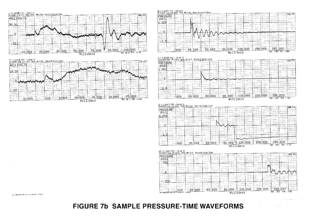
6 site in time. Therefore, there are no airblast data for this test. Thirteen events were recorded and seventeen projectile bodies were recovered--accounting for all 30 projectiles. Test Number 2 The second test was also a single pallet of projectiles; it was conducted in June Nine events or major reactions were recorded on this test. Test Number 3 The third test was a single pallet of projectiles and was conducted on July 29, Eleven events or major reactions occurred on this test. However, the last two events happened after the shut down of the tape recorder (more than 1 hour after the start of the fire). Eleven events were recorded; nineteen projectile bodies were recovered--accounting for all 30 projectiles. Test Number 4 The fourth test consisted of eight pallets of projectiles (total of 240 projectiles) and was conducted on August 29, Following the test, 174 projectile bodies were recovered intact--indicating that 66 projectiles had reacted. Based on the on-site observations and the pressure instrumentation, sixty-eight events or major reactions occurred. The pressure instrumentation indicated more reactions than there were missing projectiles--this discrepancy can be attributed to propellant-type reactions which were mistaken for projectile reactions. If a true zero time had been available, allowing the location of each event to be determined, then these propellant reactions could have been identified. Test Number 5 The fifth test consisted of eight pallets of projectiles and was conducted on April 29, Following the test, 174 projectile bodies were recovered intact--indicating that 66 projectiles had reacted. Based on the on-site observations and the pressure instrumentation, sixtynine events or major reactions occurred. The pressure instrumentation indicated more reactions than there were missing projectiles--this discrepancy can be attributed to propellant-type reactions which were mistaken for projectile reactions. If a true zero time had been available, allowing the location of each event to be determined, then these propellant reactions could have been identified. Test Number 6 The sixth test consisted of 27 pallets with each pallet containing 32 projectiles for a total of 864 projectiles. This test was conducted on October 28, Following the test, 546 projectile bodies were recovered intact--indicating that 318 projectiles had reacted. Based on the on-site observations and the pressure instrumentation, 324 events or major reactions occurred. A zero-time sensor was available for this event, therefore shock time of arrival and event locations could also be determined. There are several events for which no event zero time was measured. This could be due any of several causes. Two of the most likely, however, include: (1) the fiber optic zero time sensor becoming saturated from an event which occurred momentarily before the next reaction (2) some reactions may have been shielded from the zero time sensor if the reaction occurred on the opposite side of the stack from which the sensor was located. The difference between the number of reactions determined from the instrumentation and the
7 number of unrecovered projectiles can be attributed to propellant reactions. These reactions will be separated out and discussed in the following section. Figure 7 presents a sample of the pressure-time waveforms which were recorded on this test. Also presented is the shape of the zero time pulse which was recorded for this event. According to the pressure and optical instrumentation, the first event occurred approximately 26 minutes after the start of the fire. The zero time for the thermocouple analysis was adjusted to the time for Event 1. Any thermocouple readings taken beyond a time of approximately 25 minutes would, therefore, be suspect. Table 2 presents the maximum temperatures which occurred in the first 24 minutes of the fire. Test Number 7 The seventh test consisted of three pallets with each pallet containing 32 projectiles for a total of 96. The test was conducted on April 29, Each projectile contained Composition B explosive and was assembled with a supplementary charge. The projectiles were received with mechanical time fuses installed. These fuses were removed to comply with range safety requirements. Following the test, 82 projectile bodies were recovered intact--indicating that 14 projectiles had reacted. Based on the pressure measurements and on-site observations eight major reactions occurred. These data are still under analysis; therefore, they will not be further discussed. ANALYSIS/INTERPRETATION Only the data from Test 6 will be discussed further. This is for two reasons. Firstly, because of the large number of events involved, all of the other tests can be interpreted as sub-sets of the Test 6 data. Secondly, Test 6 provided true shock time of arrival for each event at each transducer. This allows an estimate of the event location to be made. Once the event location is determined, a yield that is based on its pressure-distance decay characteristics can be determined. This section describes the methodology which was used to estimate each event location. It then presents in both tabular and graphical form the locations determined for each event. The second half of the section deals with the determination of yield for each event. It describes the methodology which was applied and then discusses the results which were obtained--i.e., those events which appeared to be high order detonations (100% yield) and those events which were merely propellant reactions (approximately 0.1% yield or less). DETERMINATION OF EVENT LOCATIONS. An iterative procedure was set up to determine the location of each event. Because the airblast overpressures were quite low, usually below 1 or 2 psi, it was assumed that the signal propagated at sonic velocity. It was further assumed that because of the fire, there was a sound velocity gradient across the ground zero area--with the sound velocity proportional to the ambient temperature. The procedure works as follows and would be repeated for each event. An arbitrary event location is chosen (usually, the center of the ground zero area--coordinates (0,0) ). Arrival times
8 are calculated to each gauge position: radial distance between chosen event location and known gauge position divided by the sound velocity. The calculated arrival time is subtracted from the measured arrival time and the resulting difference is squared. This squared difference is summed for all of the gauge positions (P1 through P12). The event location which is reported is that location that minimizes this squared difference.. As a sensitivity check on the procedure, a constant propagation velocity (no fire-induced gradient) was assumed and several of the cases were re-run. The differences in the final locations were not significant. Because of the assumptions which were involved, it is the authors judgement that the locations presented are only accurate to about + 5 feet. These locations are presented in Figures 8, 9, and 10. These are scatter plots showing the locations of the events around the ground zero area. The immediate ground zero area was covered by a 20 x 20 concrete pad. This pad is also shown in the Figures, which are simply different views of the same information. DETERMINATION OF EVENT YIELDS. Two questions will be addressed in this section. The first is Of those events analyzed for Test 6, which ones were produced by propellant reactions? The second is Which events were true high order detonations? Based on the description of the charge which was presented earlier, airblast predictions were 11 made using Porzels Unified Theory of Explosions. Three predictions were made--a 100% yield (high order detonation), a 5% yield, and a 0.5% yield; these are shown in Figure 11. The 100% yield represents the predicted curve for the detonation of 4.5 pounds of TNT inside a 105 mm projectile body weighing approximately 24 pounds; the 0.5% yield, represents the detonation of pounds (10 grams) inside the same projectile body. These prediction curves were then 11 used to calibrate a yield determination program--dsc. The program DSC was written around concepts and techniques which were developed for the analysis of nuclear blast yields. The program evaluates a pressure-distance curve and produces an absolute yield in megacalories. The data which were presented in Figure 11 were run through the DSC program to provide a relationship between absolute yield in megacalories and a relative yield in percent. These relative yields in percent are the yields which are required for this analysis. The pressure-distance curves generated for each event were then analyzed using the computer program DSC. When an event location was not known, a location was assumed and an approximate pressure-distance curve was generated. The absolute yields which were determined were converted to relative yields. These results are presented in Figure 12. Based on the numbers of recovered projectiles, it is assumed that 318 projectiles reacted; 324 events were recorded and tabulated. Examining Figure 12, the six events with the lowest yields were selected as propellant events. All of the selected events had yields of less than 0.10%. One event was produced by a high order detonation with a yield of 100%. This was an event for which there was no zero time. Thus an estimated position was used to make the yield determination. When the six propellant events are excluded, the average yield which was observed was 10%.
9 If Figure 12 is examined closely, another trend can be discerned. As the event number increases, corresponding to increasing time after the first event or the start of the fire, the yield seems to be increasing. This may be analogous to what is observed in cook-off testing, where slow cook-off tests produce more violent results than do fast cook-off tests. SUMMARY The instrumentation described is providing valuable insight into the HD 1.2 phenomena. Based on all of the data which have been obtained to date, the HD 1.2 event appears to be a popcorntype reaction, with events occurring sequentially rather than simultaneously. A more detailed description of the information contained in this paper is presented in NSWCDD/TR-93/
10 REFERENCES 1. Henderson, J., Joint Australian/UK Stack Fragmentation Trials Phase 4 Preliminary Report, Minutes of the 24th DoD Explosives Safety Seminar, August Henderson, J.,Rees, N. M. J. Joint Australian/UK Stack Fragmentation Trials Preliminary Phase 3 Report, Minutes of the 23rd DoD Explosives Safety Seminar, August Henderson, J. et. al., Joint Australian/UK Stack Fragmentation Trials Phase 2 Report, Minutes of the 22nd DoD Explosives Safety Seminar, August Bowman, F., et. al., Joint Australian/UK Stack Fragmentation Trials Phase 1 Report, Minutes of the 21st DoD Explosives Safety Seminar, August Roger, M., Assessment of Hazardous Areas When Storing HD 1.1 Ammunition in French IGLOO TYPE Magazines, Minutes of the 25th DoD Explosives Safety Seminar, August Swisdak, M. M., Hazards Produced By Explosions Inside Earth-Covered Igloos, Minutes of the 25th DoD Explosives Safety Seminar, August Joachim, C., Shallow Underground Tunnel/Chamber Explosion Test, Minutes of the 24th DoD Explosives Safety Seminar, August Joachim, C., Accidental Detonations In Underground Munitions Storage Magazines: Predictions of Cover Rupture Pressure, Minutes of the 24th DoD Explosives Safety Seminar, August Joachim, C., Ejecta Hazard Ranges From Underground Munitions Storage Magazines, Minutes of the 24th DoD Explosives Safety Seminar, August United Nations Recommendations on the Transport of Dangerous Goods, Tests and Criteria, Second Edition, ST/SG/AC.10/11/Rev Porzel, F. B., Technology Base of the Navy Explosives Safety Improvement Program, Minutes of the 19th DoD Explosives Safety Seminar, Sep Swisdak, M. M., Jr. and Rye, Kent W., Hazard Division 1.2 Tests--Instrumentation Results and Interpretation, NSWCDD/TR-93/218, 9 March 1994.

11
12
13
14
15
16
17
18
19
20

21
22
23
24
25
26
27
TEST WIRE FOR HIGH VOLTAGE POWER SUPPLY CROWBAR SYSTEM
 TEST WIRE FOR HIGH VOLTAGE POWER SUPPLY CROWBAR SYSTEM Joseph T. Bradley III and Michael Collins Los Alamos National Laboratory, LANSCE-5, M.S. H827, P.O. Box 1663 Los Alamos, NM 87545 John M. Gahl, University
HIGH VOLTAGE SWITCH PERFORMANCE OF THE EIMAC X-2159 TETRODE ABSTRACT
 HIGH VOLTAGE SWITCH PERFORMANCE OF THE EIMAC X-2159 TETRODE by Bobby R. Gray High Power Component & Effects Section Techniques Branch Surveillance Division Rome Air Development Center Griffiss Air Force
REPORT DOCUMENTATION PAGE
 REPORT DOCUMENTATION PAGE Form Approved OMB No. 0704-0188 Public reporting burden for this collection of information is estimated to average 1 hour per response, including the time for reviewing instructions,
A Look-up-table Approach to Inverting Remotely Sensed Ocean Color Data
 A Look-up-table Approach to Inverting Remotely Sensed Ocean Color Data W. Paul Bissett Florida Environmental Research Institute 4807 Bayshore Blvd. Suite 101 Tampa, FL 33611 phone: (813) 837-3374 x102
Processing the Output of TOSOM
 Processing the Output of TOSOM William Jackson, Dan Hicks, Jack Reed Survivability Technology Area US Army RDECOM TARDEC Warren, Michigan 48397-5000 ABSTRACT The Threat Oriented Survivability Optimization
Continued Development of the Look-up-table (LUT) Methodology for Interpretation of Remotely Sensed Ocean
 Methodology for Interpretation of Remotely Sensed Ocean") Continued Development of the Look-up-table (LUT) Methodology for Interpretation of Remotely Sensed Ocean Curtis D. Mobley Sequoia Scientific, Inc. 2700 Richards Road, Suite 107 Bellevue, WA 98005 phone:
Continued Development of the Look-up-table (LUT) Methodology for Interpretation of Remotely Sensed Ocean Curtis D. Mobley Sequoia Scientific, Inc. 2700 Richards Road, Suite 107 Bellevue, WA 98005 phone:
RADIOGRAPHIC PERFORMANCE OF CYGNUS 1 AND THE FEBETRON 705
 RADIOGRAPHIC PERFORMANCE OF CYGNUS 1 AND THE FEBETRON 705 E. Rose ξ, R. Carlson, J. Smith Los Alamos National Laboratory, PO Box 1663, Mail Stop P-947 Los Alamos, NM 87545, USA Abstract Spot sizes are
A Comparison of the Temporal Characteristics of LCS, LCoS, Laser, And CRT Projectors
 AFRL-HE-AZ-TM-2006-0001 A Comparison of the Temporal Characteristics of LCS, LCoS, Laser, And CRT Projectors George A. Geri Link Simulation and Training 6030 South Kent Street Mesa, AZ 85212 William D.
AFRL-RY-WP-TR
 AFRL-RY-WP-TR-2017-0172 SIGNAL PROCESSING UTILIZING RADIO FREQUENCY PHOTONICS Preetpaul S. Devgan RF/EO Subsystems Branch Aerospace Components & Subsystems Division SEPTEMBER 2017 Final Report See additional
PREPARED FOR: U.S. Army Medical Research and Materiel Command Fort Detrick, Maryland
 AWARD NUMBER: W81XWH-13-1-0491 TITLE: Default, Cognitive, and Affective Brain Networks in Human Tinnitus PRINCIPAL INVESTIGATOR: Jennifer R. Melcher, PhD CONTRACTING ORGANIZATION: Massachusetts Eye and
Search Strategies for a Wide-Field Electro-Optic Sensor
 Search Strategies for a Wide-Field Electro-Optic Sensor R. Lambour, E. Pearce, R. Sayer 21 Space Control Conference 4 April 21 This work sponsored by the Air Force under Air Force Contract F19628--C-2.
Applying LaPO 4 Phosphor via Spinning for BetaPhotovoltaic Devices
 ARL-TR-7269 JUN 2015 US Army Research Laboratory Applying LaPO 4 Phosphor via Spinning for BetaPhotovoltaic Devices by Muhammad R Khan, Joshua R Smith, Kevin Kirchner, and Kenneth A Jones Approved for
UNITED STATES AIR FORCE RESEARCH LABORATORY
 AFRL-HE-AZ-SR-2002-0005 UNITED STATES AIR FORCE RESEARCH LABORATORY IMAGE GENERATOR REQUIREMENTS FOR DRIVING THE 5120 x 4096 PIXEL ULTRA HIGH-RESOLUTION LASER PROJECTOR Ben L. Surber L-3 Communications
RATE-ADAPTIVE VIDEO CODING (RAVC)
") AFRL-RI-RS-TR-2008-140 Final Technical Report May 2008 RATE-ADAPTIVE VIDEO CODING (RAVC) FastVDO LLC APPROVED FOR PUBLIC RELEASE; DISTRIBUTION UNLIMITED. STINFO COPY AIR FORCE RESEARCH LABORATORY INFORMATION
AFRL-RI-RS-TR-2008-140 Final Technical Report May 2008 RATE-ADAPTIVE VIDEO CODING (RAVC) FastVDO LLC APPROVED FOR PUBLIC RELEASE; DISTRIBUTION UNLIMITED. STINFO COPY AIR FORCE RESEARCH LABORATORY INFORMATION
THE LIQUID METAL PLASMA VALVE CLOSIN"G SWITCH. John R. Bayless Hughes Research Laboratories 3011 Malibu Canyon Road Malibu, California
 THE LIQUID METAL PLASMA VALVE CLOSIN"G SWITCH by John R. Bayless Hughes Research Laboratories 3011 Malibu Canyon Road Malibu, California 90265 and Joseph P. Heckl Naval Surface Weapons Center Silver Spring,
THE EXPLOSIVE PULSED POWER TEST FACILITY AT AFRL
 THE EXPLOSIVE PULSED POWER TEST FACILITY AT AFRL J. V. Parker, T. C. Cavazos, C. E. Roth, D. R. Sandoval and W. Sommars Science Applications International Corp., Albuquerque, NM 87106 F. M. Lehr, G. F.
Multiple Target Laser Designator (MTLD)
") Multiple Target Laser Designator (MTLD) Quarterly Status Report #6 Contract No. N00014-05-C-0423 Period of Performance: 08/23/05 to 04/23/07 Reporting Period: 11/24/06 to 02/23/07 Technical Monitor: Dr.
Multiple Target Laser Designator (MTLD) Quarterly Status Report #6 Contract No. N00014-05-C-0423 Period of Performance: 08/23/05 to 04/23/07 Reporting Period: 11/24/06 to 02/23/07 Technical Monitor: Dr.
Self Excited Automatic Voltage Regulator For Generator Compatible with Marathon SE350* Operation Manual
 Self Excited Automatic Voltage Regulator For Generator Compatible with Marathon SE350* Operation Manual s * Use for reference purpose only and not a genuine Marathon product. 1. INTRODUCTION Sensing Input
SPECIFICATION NO NOTE
 NOTE The Model 207-1 is a special version of the standard M-207 Power Supply. It has been altered for a special applications requiring low current operation at high arc voltages in ambient and pressurized
VOD/DATA RECORDERS AND ACCESSORIES FOR ASSOCIATED APPLICATIONS PRODUCT LIST
 VOD/DATA RECORDERS AND ACCESSORIES FOR ASSOCIATED APPLICATIONS PRODUCT LIST MREL DOCUMENT #: PROD180102 THESE PRODUCTS AND PRICES ARE AVAILABLE TO PRE-SCREENED, PRE-APPROVED CUSTOMERS ONLY. PRICES ARE
LAUREL. Laureate Digital Panel Meter for Load Cell & Microvolt Input ELECTRONICS, INC. Features. Description
 Description LAUREL ELECTRONICS, INC. Features Laureate Digital Panel Meter for Load Cell & Microvolt Input 20, 50, 100, 250 & 500 mv ranges Span adjust from 0 to ±99,999, zero adjust from -99,999 to +99,999
Fig. 1. Hawk switch/load vacuum section in the standard configuration.
 PLASMA OPENING SWITCH EXPERIMENTS ON HAWK WITH AN E-BEAM DIODE LOAD P.J. Goodrich,* J.R. Boller, R.J. Commisso, D.O. Hinshelwood,* J.C. Kellogg, B.V. Weber Pulsed Power Physics Branch, Plasma Physics Division
Advances in Telemetry Capability as Demonstrated on an Affordable Precision Mortar
 Advances in Telemetry Capability as Demonstrated on an Affordable Precision Mortar by Michael L. Don ARL-RP-378 June 2012 A reprint from Proceedings of the International Telemetry Conference, Las Vegas,
SPECIAL SPECIFICATION 6911 Fiber Optic Video Data Transmission Equipment
 2004 Specifications CSJ 3256-02-079 & 3256-03-082 SPECIAL SPECIFICATION 6911 Fiber Optic Video Data Transmission Equipment 1. Description. Furnish and install Fiber Optic Video Data Transmission Equipment
The State of Remote Scientific Visualization Providing Local Graphics Performance to Remote ARL MSRC Users
 The State of Remote Scientific Visualization Providing Local Graphics Performance to Remote ARL MSRC Users by John M. Vines and Claude Sandroff ARL-TR-3635 September 2005 Approved for public release; distribution
SPECIAL SPECIFICATION 1291 Fiber Optic Video Data Transmission Equipment
 1993 Specifications CSJ 0500-01-117 SPECIAL SPECIFICATION 1291 Fiber Optic Video Data Transmission Equipment 1. Description. This Item shall govern for the furnishing and installation of Fiber Optic Video
THE WSMR TIMING SYSTEM: APPROACHING THE HORIZON. William A. Gilbert White Sands Missile Range, New Mexico. Abstract
 2gth Annual Pmbe Time and Time Internal (PTTI) Meeting THE WSMR TIMING SYSTEM: APPROACHING THE HORIZON William A. Gilbert White Sands Missile Range, New Mexico Abstract Over the past couple of years, WSMR
REPORT DOCUMENTATION PAGE
 REPORT DOCUMENTATION PAGE Form Approved OMB NO. 0704-0188 Public Reporting burden for this collection of informal is estimated to average 1 hour per response, including the time for revtewmg instructions,
Failure Modes, Effects and Diagnostic Analysis
 Failure Modes, Effects and Diagnostic Analysis Project: United Electric One Series Electronic Switch Customer: United Electric Watertown, MA USA Contract No.: UE 05/10-35 Report No.: UE 05/10-35 R001 Version
SPECIFICATION NO Model 207 Automatic GTAW Welding System
 1.0 Introduction The Model 207 is a completely self-contained Gas Tungsten Arc Welding (GTAW) System requiring only input power, inert gas and AMI Welding Head (or manual torch) for operation. Its small
SingMai Electronics SM06. Advanced Composite Video Interface: HD-SDI to acvi converter module. User Manual. Revision 0.
 SM06 Advanced Composite Video Interface: HD-SDI to acvi converter module User Manual Revision 0.4 1 st May 2017 Page 1 of 26 Revision History Date Revisions Version 17-07-2016 First Draft. 0.1 28-08-2016
Concept of Operations (CONOPS)
") PRODUCT 0-6873-P1 TxDOT PROJECT NUMBER 0-6873 Concept of Operations (CONOPS) Jorge A. Prozzi Christian Claudel Andre Smit Praveen Pasupathy Hao Liu Ambika Verma June 2016; Published March 2017 http://library.ctr.utexas.edu/ctr-publications/0-6873-p1.pdf
PRODUCT 0-6873-P1 TxDOT PROJECT NUMBER 0-6873 Concept of Operations (CONOPS) Jorge A. Prozzi Christian Claudel Andre Smit Praveen Pasupathy Hao Liu Ambika Verma June 2016; Published March 2017 http://library.ctr.utexas.edu/ctr-publications/0-6873-p1.pdf
EA63-7D. Generator Automatic Voltage Regulator Operation Manual. Self Excited Automatic Voltage Regulator
 EA63-7D Generator Automatic Voltage Regulator Operation Manual Self Excited Automatic Voltage Regulator SP POWERWORLD LTD Willows, Waterside, Ryhall, Stamford, Lincs, PE9 4EY, UK Tel: +44 1780 756872 -
Implementation of LED Roadway Lighting
 Implementation of LED Roadway Lighting Ken Taillon, Principal Investigator Short Elliot Hendrickson, Inc. (SEH ) May 2016 Research Project Final Report 2016-17 To request this document in an alternative
 I R T Electronics Pty Ltd A.B.N. 35 000 832 575 26 Hotham Parade, ARTARMON N.S.W. 2064 AUSTRALIA National: Phone: (02) 9439 3744 Fax: (02) 9439 7439 International: +61 2 9439 3744 +61 2 9439 7439 Email:
The Syscal family of resistivity meters. Designed for the surveys you do.
 The Syscal family of resistivity meters. Designed for the surveys you do. Resistivity meters may conveniently be broken down into several categories according to their capabilities and applications. The
SECTION 686 VIDEO DECODER DESCRIPTION
 686 SECTION 686 VIDEO DECODER DESCRIPTION 686.01.01 GENERAL A. This specification describes the functional, performance, environmental, submittal, documentation, and warranty requirements, as well as the
Emcore SITU2831 Externally Modulated RF Amplified Fiber Optic Transmitter and SIRU3000 Fiber Optic Receiver
 PRELIMINARY Applications RF and microwave antenna signal distribution EW Systems Broadband delay-line and signal processing systems Frequency distribution systems Radar system calibration Phased array
SingMai Electronics SM06. Advanced Composite Video Interface: DVI/HD-SDI to acvi converter module. User Manual. Revision th December 2016
 SM06 Advanced Composite Video Interface: DVI/HD-SDI to acvi converter module User Manual Revision 0.3 30 th December 2016 Page 1 of 23 Revision History Date Revisions Version 17-07-2016 First Draft. 0.1
RF MEMS IMPROVEMENT PROGRAM
 AFRL-SN-RS-TR-2005-62 Final Technical Report March 2005 RF MEMS IMPROVEMENT PROGRAM L-3 Government Services, Inc. Sponsored by Defense Advanced Research Projects Agency DARPA Order No. M606 APPROVED FOR
Series CT7N Bimetallic Overload Relays
 Series CT7N imetallic Overload Relays Choose CT7N overloads in DC applications and when monitoring Variable Frequency Drives Sprecher + Schuh has always paid particular attention to the subject of motor
1995 Metric CSJ SPECIAL SPECIFICATION ITEM 6031 SINGLE MODE FIBER OPTIC VIDEO TRANSMISSION EQUIPMENT
 1995 Metric CSJ 0508-01-258 SPECIAL SPECIFICATION ITEM 6031 SINGLE MODE FIBER OPTIC VIDEO TRANSMISSION EQUIPMENT 1.0 Description This Item shall govern for the furnishing and installation of color Single
LONWORKS Fibre Optic Converter
 LONWORKS Fiber Optic Converter LRW-102 and LRW-102/PP LONWORKS to fibre optic link, multidrop and redundant ring applications The LRW-102 is a fibre optic modem designed for multidrop and redundant ring
High Density Digital Recorder Application Study-The AN/BQH-9(V)1 Program
1 Program") High Density Digital Recorder Application Study-The AN/BQH-9(V)1 Program THIC Conference October 13, 14, 1998 CARDEROCK DIVISION NAVAL SURFACE WARFARE CENTER Prepared by John Jester DDL OMNI Engineering
High Density Digital Recorder Application Study-The AN/BQH-9(V)1 Program THIC Conference October 13, 14, 1998 CARDEROCK DIVISION NAVAL SURFACE WARFARE CENTER Prepared by John Jester DDL OMNI Engineering
SC24 Magnetic Field Cancelling System
 SPICER CONSULTING SYSTEM SC24 SC24 Magnetic Field Cancelling System Makes the ambient magnetic field OK for the electron microscope Adapts to field changes within 100 µs Touch screen intelligent user interface
Digital Logic Design: An Overview & Number Systems
 Digital Logic Design: An Overview & Number Systems Analogue versus Digital Most of the quantities in nature that can be measured are continuous. Examples include Intensity of light during the day: The
FP-QUAD-510. Features. Power Requirement OPERATING INSTRUCTIONS. 4-Axis, Quadrature Input Module
 OPERATING INSTRUCTIONS FP-QUAD-510 4-Axis, Quadrature Input Module These operating instructions describe the installation, features, and characteristics of the FP-QUAD-510. For details on configuring and
SC24 Magnetic Field Cancelling System
 SPICER CONSULTING SYSTEM SC24 SC24 Magnetic Field Cancelling System Makes the ambient magnetic field OK for the electron microscope Adapts to field changes within 100 µs Touch screen intelligent user interface
4830A Accelerometer simulator Instruction manual. IM4830A, Revision E1
 4830A Accelerometer simulator Instruction manual IM4830A, Revision E1 IM4830, Page 2 The ENDEVCO Model 4830A is a battery operated instrument that is used to electronically simulate a variety of outputs
EA350. Generator Automatic Voltage Regulator Operation Manual
 Generator Automatic Voltage Regulator Operation Manual Self Excited Automatic Voltage Regulator For General Generators Compatible with Marathon SE350* * Use for reference purpose only and not a genuine
Current Status of the Laser Diode Array Projector Technology
 Current Status of the Laser Diode Array Projector Technology D. Brett Beasley and Daniel A. Saylor, Optical Sciences Corporation, P.O. Box 8291, Huntsville, AL 35808 ABSTRACT This paper describes recent
LAUREL ELECTRONICS, INC.
 LAUREL ELECTRONICS, INC. Laureate Digital Panel Meter for Process, Strain & Potentiometer Follower Signals Features Selectable ±0.2, ±2, ±20, ±200, ±300 & ±600 Vdc voltage ranges Selectable ±2, ±20, ±200
In-process inspection: Inspector technology and concept
 Inspector In-process inspection: Inspector technology and concept Need to inspect a part during production or the final result? The Inspector system provides a quick and efficient method to interface a
NOTICE. The above identified patent application is available for licensing. Requests for information should be addressed to:
 > - Serial Number 09/565.234 Filine Date 28 April 2000 Inventor John R. Raposa Daniel P. Thivierge NOTICE The above identified patent application is available for licensing. Requests for information should
SERIAL HIGH DENSITY DIGITAL RECORDING USING AN ANALOG MAGNETIC TAPE RECORDER/REPRODUCER
 SERIAL HIGH DENSITY DIGITAL RECORDING USING AN ANALOG MAGNETIC TAPE RECORDER/REPRODUCER Eugene L. Law Electronics Engineer Weapons Systems Test Department Pacific Missile Test Center Point Mugu, California
Process Transmitter RMA 422
 Technical Information TI 072R/24/ae Process Transmitter RMA 422 Multi-functional 1-2 channel top hat DIN rail unit with loop power supply, alarm set point monitoring, mathematics function and 1-2 analog
Modular Lube Lubrication Systems System Controls
 Model 84501 Program Timer Solid State Designed to control the lubrication cycle frequency of air-operated single-stroke pumps. Timer turns pump on/off at programmed intervals via a 3-way or 4-way air solenoid
SC26 Magnetic Field Cancelling System
 SPICER CONSULTING SYSTEM SC26 SC26 Magnetic Field Cancelling System Makes the ambient magnetic field OK for electron beam tools in 300 mm wafer fabs Real time, wideband cancelling from DC to > 9 khz fields
MX1609. Data Sheet. Thermocouple amplifier. Special features. Block diagram. B en
 MX1609 Thermocouple amplifier Data Sheet Special features 16 inputs Connection of type K thermo couples to mini thermocouple sockets Measuring point identification via RFID Internal cold junction compensation
Stud Welding Equipment
 Stud Welding Equipment 10/16 N550c Arc Charger Breakthrough Charger design provides powerful 550A Arc Welder from 120V wall outlet! The N550c Arc Charger is the first of a revolutionary new class of stud
w. R. Scarlett, K. R. Andrews, H. Jansen
 261 11.2 A LARGE-AREA COLD-CATHODE GRID-CONTROLLED ELECTRON GUN FOR ANTARES* w. R. Scarlett, K. R. Andrews, H. Jansen Abstract University of California, Los Alamos Scientific Laboratory The C0 2 1 aser
UDC100 Universal Digital Controller. Specification. Overview. Features. Features, continued /99 Page 1 of 4
 UDC100 Universal Digital Controller 51-52-03-29 11/99 Page 1 of 4 Specification Overview The UDC100 Universal Digital Controller is a microprocessor-based 1/4 DIN low cost temperature controller. It combines
Color mixing or White-light LED (Light Emitting Diode) ERS-style product
 ERS-style product") WHT Color mixing or White-light LED (Light Emitting Diode) ERS-style product GENERAL PHYSICAL A. The product shall be an Ovation E-910FC as manufactured by Chauvet & Sons, LLC or approved equal. 1. The
WHT Color mixing or White-light LED (Light Emitting Diode) ERS-style product GENERAL PHYSICAL A. The product shall be an Ovation E-910FC as manufactured by Chauvet & Sons, LLC or approved equal. 1. The
Application Note #63 Field Analyzers in EMC Radiated Immunity Testing
 Application Note #63 Field Analyzers in EMC Radiated Immunity Testing By Jason Galluppi, Supervisor Systems Control Software In radiated immunity testing, it is common practice to utilize a radio frequency
HONEYWELL VIDEO SYSTEMS HIGH-RESOLUTION COLOR DOME CAMERA
 Section 00000 SECURITY ACCESS AND SURVEILLANCE HONEYWELL VIDEO SYSTEMS HIGH-RESOLUTION COLOR DOME CAMERA PART 1 GENERAL 1.01 SUMMARY The intent of this document is to specify the minimum criteria for the
STUDIES OF ENHANCED EDGE EMISSION OF A LARGE AREA CATHODE *
 STUDIES OF ENHANCED EDGE EMISSION OF A LARGE AREA CATHODE * F. Hegeler, M. Friedman, M.C. Myers, S.B. Swanekamp, and J.D. Sethian Plasma Physics Division, Code 6730 Naval Research Laboratory, Washington,
MILITARY SPECIFICATION SHEET
 INCH POUND MIL-S-22885/100A 16 May 2003 SUPERSEDING MIL-S-22885/100 (USAF) 27 August 1982 MILITARY SPECIFICATION SHEET SWITCH, PUSH BUTTON, ILLUMINATED, 4-LAMP, SPDT AND DPDT, 7.5 AMPERES, SILVER CONTACTS,
Guide for installers. METTLER TOLEDO MultiRange System solution analog Ex1. Hazardous area. Safe area
 Guide for installers METTLER TOLEDO MultiRange System solution analog Ex1 Hazardous area Safe area System solution analog Ex1 Contents Contents Page 1 Safety precautions... 2 2 System overview... 3 2.1
SPECIAL SPECIFICATION 1987 Single Mode Fiber Optic Video Transmission Equipment
 1993 Specifications CSJ 0027-12-086, etc. SPECIAL SPECIFICATION 1987 Single Mode Fiber Optic Video Transmission Equipment 1. Description. This Item shall govern for the furnishing and installation of color
DISTRIBUTION AMPLIFIER
 MANUAL PART NUMBER: 400-0045-005 DA1907SX 1-IN, 2-OUT VGA/SVGA/XGA/UXGA DISTRIBUTION AMPLIFIER USER S GUIDE TABLE OF CONTENTS Page PRECAUTIONS / SAFETY WARNINGS... 2 GENERAL...2 GUIDELINES FOR RACK-MOUNTING...2
OPTIMUM Power Technology: Low Cost Combustion Analysis for University Engine Design Programs Using ICEview and NI Compact DAQ Chassis
 OPTIMUM Power Technology: Low Cost Combustion Analysis for University Engine Design Programs Using ICEview and NI Compact DAQ Chassis World Headquarters (USA): European Sales Office: Japanese Office: 3117
VBOX3i Dual Antenna. Measures Slip and Pitch/Roll (RLVB3iSL) Features
 Features") VBOX3i dual antenna (VB3iSL) is Racelogic s most powerful GPS data logging system. By utilising two GPS engines configured in a Fixed Baseline RTK setup, the VB3iSL combines high level accuracy and test
VBOX3i dual antenna (VB3iSL) is Racelogic s most powerful GPS data logging system. By utilising two GPS engines configured in a Fixed Baseline RTK setup, the VB3iSL combines high level accuracy and test
DCT 532. Industrial Pressure Transmitter with i²c interface. Stainless Steel Sensor
 Industrial Pressure Transmitter with i²c interface Stainless Steel Sensor Accuracy according to IEC 60770: standard: ± 0. % FSO option: ± 0. % FSO Nominal pressure from 0... 00 mbar up to 0... 00 bar Digital
Application of Measurement Instrumentation (1)
") Slide Nr. 0 of 23 Slides Application of Measurement Instrumentation (1) Slide Nr. 1 of 23 Slides Application of Measurement Instrumentation (2) a. Monitoring of processes and operations 1. Thermometers,
Slide Nr. 0 of 23 Slides Application of Measurement Instrumentation (1) Slide Nr. 1 of 23 Slides Application of Measurement Instrumentation (2) a. Monitoring of processes and operations 1. Thermometers,
SPECIAL SPECIFICATION :1 Video (De) Mux with Data Channel
 Mux with Data Channel") 1993 Specifications CSJ 0924-06-223 SPECIAL SPECIFICATION 1160 8:1 Video (De) Mux with Data Channel 1. Description. This Item shall govern for furnishing and installing an 8 channel digital multiplexed
1993 Specifications CSJ 0924-06-223 SPECIAL SPECIFICATION 1160 8:1 Video (De) Mux with Data Channel 1. Description. This Item shall govern for furnishing and installing an 8 channel digital multiplexed
PREPARED FOR: U.S. Army Medical Research and Materiel Command Fort Detrick, Maryland
 AWARD NUMBER: W81XWH-14-2-0180 TITLE: Development of a Device for Objective Assessment of Tinnitus in Humans PRINCIPAL INVESTIGATOR: Jeremy G. Turner, PhD CONTRACTING ORGANIZATION: OtoScience Labs, LLC
Agilent N9355/6 Power Limiters 0.01 to 18, 26.5 and 50 GHz
 Agilent N9355/6 Power Limiters 0.01 to 18, 26.5 and 50 GHz Technical Overview High Performance Power Limiters Broad frequency range up to 50 GHz maximizes the operating range of your instrument High power
Process transmitter RMA422
 Technical information TI072R/09/en Mat. No. 51001905 Process transmitter RMA422 Multifunctional 1-2 channel top hat DIN rail unit with intrinsically safe current input and loop power supply, alarm set
Award Number: W81XWH-
 AD Award Number: W81XWH- TITLE: PRINCIPAL INVESTIGATOR: CONTRACTING ORGANIZATION: REPORT DATE: TYPE OF REPORT: Annual PREPARED FOR: U.S. Army Medical Research and Materiel Command Fort Detrick, Maryland
Specifications. Reference Documentation. Performance Conditions
 The material in this section is organized into two main groupings: the specification tables and the supporting figures. The specification tables include: 1. PAL general and test signal specifications 2.
 APPLICATIONS typical application: Lighting automation Other applications of the SO and SI line of controllers: HVAC automation Industrial automation OVERVIEW The S Series are microprocessor based I/O controllers
1993 Specifications CSJ , etc. SPECIAL SPECIFICATION ITEM CCTV Central Equipment
 1993 Specifications CSJ 0922-33-042, etc. SPECIAL SPECIFICATION ITEM 8549 CCTV Central Equipment 1. Description. This Item shall govern for the furnishing and installation of closed circuit television
ITER Product Catalog Total Pressure Measurement. ITER Product Catalogue Total Pressure Measurement V Page 1 / 15
 ITER Product Catalogue Total Pressure Measurement V201612 Page 1 / 15 Content TPG 300 Passive Gauge Controller... 3 Pirani/Cold Cathode Measurement Board... 5 Interface and Relay Boards... 6 Pirani Gauge
456 SOLID STATE ANALOGUE TAPE + A80 RECORDER MODELS
 456 SOLID STATE ANALOGUE TAPE + A80 RECORDER MODELS 456 STEREO HALF RACK 456 MONO The 456 range in essence is an All Analogue Solid State Tape Recorder the Output of which can be recorded by conventional
ITER Product Catalogue. Total Pressure Measurement V Page 1 / 15
 ITER Product Catalogue V20170405 Page 1 / 15 Content TPG 300 Passive Gauge Controller... 3 Pirani/Cold Cathode Measurement Board... 5 Interface and Relay Boards... 6 Pirani Gauge TPR 018... 7 Cold Cathode
Salient Systems June, N Mopac Expy, Bldg 3, Ste 700 Austin, Texas FAX
 Salient Systems June, 2014 10801 N Mopac Expy, Bldg 3, Ste 700 Austin, Texas 78759 512-617-4800 512-617-4801 FAX www.salientsys.com Product Guide Specification Specifier Notes: This product guide specification
T ips in measuring and reducing monitor jitter
 APPLICAT ION NOT E T ips in measuring and reducing Philips Semiconductors Abstract The image jitter and OSD jitter are mentioned in this application note. Jitter measuring instruction is also included.
TSG 90 PATHFINDER NTSC Signal Generator
 Service Manual TSG 90 PATHFINDER NTSC Signal Generator 070-8706-01 Warning The servicing instructions are for use by qualified personnel only. To avoid personal injury, do not perform any servicing unless
Limiter RLM Ω Broadband 950 to 2050 MHz. The Big Deal
 +5 to +30 dbm Limiter 50Ω Broadband 950 to 2050 MHz The Big Deal High CW input power, 1 W Very low limiting output power, 0 dbm typ. Very fast response time, 2 nsec CASE STYLE: CK1246-1 Product Overview
A MISSILE INSTRUMENTATION ENCODER
 A MISSILE INSTRUMENTATION ENCODER Item Type text; Proceedings Authors CONN, RAYMOND; BREEDLOVE, PHILLIP Publisher International Foundation for Telemetering Journal International Telemetering Conference
Medium Weight Shock and Vibration Test Report on 3 x 1 1/2 x 6 15 HP Pump for Sims Pump Valve Company Hoboken, NJ
 Report No. 10405.1 No. of Pages 16 Medium Weight Shock and Vibration Test Report on 3 x 1 1/2 x 6 15 HP Pump for Sims Pump Valve Company Hoboken, NJ NU LABORATORIES, INC. 312 Old Allerton Road, Annandale,
COHERENCE ONE PREAMPLIFIER
 COHERENCE ONE PREAMPLIFIER OWNER S MANUAL TABLE OF CONTENTS Introduction Features Unpacking Instructions Installation Phono Cartridge Loading Basic Troubleshooting Technical Specifications Introduction
Noise Detector ND-1 Operating Manual
 Noise Detector ND-1 Operating Manual SPECTRADYNAMICS, INC 1849 Cherry St. Unit 2 Louisville, CO 80027 Phone: (303) 665-1852 Fax: (303) 604-6088 Table of Contents ND-1 Description...... 3 Safety and Preparation
e'a&- A Fiber Optic Wind Vane: A Conceptual View (U)
") W SRC-MS-96-0228 e'a&- A Fiber Optic Wind Vane: A Conceptual View (U) 9604/37--L by M. J. Parker Westinghouse Savannah River Company Savannah River Site Aiken, South Carolina 29808 M. Heaverly Met One
W SRC-MS-96-0228 e'a&- A Fiber Optic Wind Vane: A Conceptual View (U) 9604/37--L by M. J. Parker Westinghouse Savannah River Company Savannah River Site Aiken, South Carolina 29808 M. Heaverly Met One
Re: ENSC 370 Project Physiological Signal Data Logger Functional Specifications
 School of Engineering Science Simon Fraser University V5A 1S6 versatile-innovations@sfu.ca February 12, 1999 Dr. Andrew Rawicz School of Engineering Science Simon Fraser University Burnaby, BC V5A 1S6
SCALE & WEIGHT DISPLAYS
 The MICRO SERIES SCALE & WEIGHT DISPLAYS LARGE DIGIT MODELS Mighty-5S DPM MODELS Micro-S & Mighty-1S Mighty-1S Micro-S ELECTRO-NUMERICS, INC. Introduction The Electro-Numerics family of Digital Panel Meters
1.5mm amplitude at 10 to 55Hz frequency in each X, Y, Z direction for 2 hours 500m/s² (approx. 50G) in each X, Y, Z direction for 3 times
 in each X, Y, Z direction for 3 times") Color Mark Color Mark Feature Outstanding color matching accuracy - RGB light emitting diodes and 12-bit resolution - 2 detection modes (color only / color + intensity) - -step sensitivity adjustment for
Color Mark Color Mark Feature Outstanding color matching accuracy - RGB light emitting diodes and 12-bit resolution - 2 detection modes (color only / color + intensity) - -step sensitivity adjustment for
RMX-44 & RMX-62 MIXING MATRIX. Installation & Operation Manual
 RMX-44 & RMX-6 MIXING MATRIX Installation & Operation Manual TABLE OF CONTENTS RMX-44 & RMX-6 INTRODUCTION... RMX-44 CALLOUTS... RMX-44 BLOCK DIAGRAM... RMX-6 CALLOUTS... 4 RMX-6 BLOCK DIAGRAM... 5 RMX-44
cdaq-itc Data Sheet cdaq Isolated Thermocouple Module Special Features Block Diagram B en
 cdaq-itc cdaq Isolated Thermocouple Module Data Sheet Special Features - 16 channels of isolated thermocouple signal conditioning - Available for K-, J- or T-type thermocouples - Individual channel cold
Medium Weight Shock and Vibration Test Report on 3 x 1.5 x 8 Pump with 30 HP Motor for Sims Pump Valve Company, Inc. Hoboken, NJ
 Test Report No. 10490.1 No. of Pages 16 Medium Weight Shock and Vibration Test Report on 3 x 1.5 x 8 Pump with 30 HP Motor for Sims Pump Valve Company, Inc. Hoboken, NJ NU LABORATORIES, INC. 312 Old Allerton