DATV-Express Users Guide. (based on DATV-Express software build v1.09) Draft 16
|
|
|
- Brianna Bryant
- 5 years ago
- Views:
Transcription


1 DATV-Express Users Guide (based on DATV-Express software build v1.09) Draft 16 1
2 Table of Contents 1.0 Prepare Disk Drive on PC Just reformat and devote the entire single drive for Ubuntu Use a two drive system install Windows Ubuntu on a single partitioned drive WindowsXP environment Windows7 environment Install Ubuntu Version LTS Install DATV Express software package using Debian installation Hook up the DATV hardware and Test Here is what you need First test power up the DATV Express board by itself Second test connect the hardware board and start DATV Express sw Third test now connect video capture to the PC Fourth test Transmitting DATV video DATV Express GUI Reference Guide DVB S Tab Forward Error Correction (FEC) APPLY DVB S2 Tab MODULATION CODE RATE (FEC) ROLL OFF FRAME TYPE NULL PACKET DETECTION DVB T Tab MODE CONSTELLATION ALPHA GUARD PERIOD FEC RATE CHANNEL APPLY DVB T2 Tab SR (Symbol Rate) Tab Symbol Rate (SR) APPLY TX Tab TRANSMITTER FREQUENCY TRANSMITTER LEVEL APPLY PIDs (Packet IDs) Tab PMT PID
3 5.7.2 VIDEO PID AUDIO PID PCR PID DATA PID Typical PID Values APPLY SVC (Program) INFO Tab SERVICE PROVIDER NAME SERVICE NAME APPLY EPG (Electronic Program Guide) Tab DURATION (MINS) Field EVENT TITLE EVENT Text APPLY HW (HARDWARE) Tab VIDEO CAPTURE DEVICE CAPTURE DEVICE TYPE INPUT SELECTOR TRANSMITTER ENABLE CALIBRATION (Checkbox) SERVER IP ADDRESS SOCKET NUMBER APPLY MODE Tab DVB MODE APPLY MAIN Tab TRANSMIT QUEUE NULLS INSERTED TRANSMIT DELAY CARRIER (Checkbox) TS LOG TO FILE (Checkbox) PTT (Button) Board LEDs Useful utilities DATV Express specs

4 1.0 Prepare Disk Drive on PC The DATV-Express requires a PC to perform most of the DVB-S processing and then the PC will send the IQ stream to the DATV-Express hardware board via USB2 connection. See Figure 1 below for a block diagram of a typical DATV-Express transmitter set-up Figure 1 Block Diagram of typical DATV-Express transmitter set-up Currently the DATV-Express software only runs on 32-bit or 64-bit Ubuntu Operating/System (O/S). The first step is to select which disk drive you will use on the PC for the Ubuntu (linux) operating system. There are at least three approaches for the Ubuntu disk drive. Section 1.1 guides you to just completely reformatting your existing disk drive, and the loading Ubuntu O/S onto the reformatted drive. Section 1.2 guides you to install a second disk drive into your PC and devoting the second drive to the Ubuntu O/S. This way the original first drive can continue to run a different operating system like Windows. The third approach in Section 1.3 will guide you to re-partition an existing Widows disk drive to hold both the existing Windows O/S as well as the newly loaded Ubuntu O/S Just reformat and devote the entire single drive for Ubuntu If you currently have Windows on a computer and are willing to get rid of Windows, then... download Ubuntu Ver LTS onto your Windows disk now burn the Ubuntu to a CD-ROM or DVD in ISO format so it will boot from your CD-ROM or DVD drive Go to the PC BIOS and configure to boot from CD-ROM drive Put the Ubuntu ISO CD-ROM/DVD image into the DVD drive and power cycle the PC to boot from the Ubuntu ISO image. Proceed with the steps towards installing Ubuntu, the software will ask you if you want to reformat the drive...say YES Use a two drive system You can elect to add a new disk drive to your existing PC cabinet if the cabinet has room for a second drive. The new drive should have the same disk interface cable connector as the existing disk drive. Bolt in the new drive and connect the power cable to the drive and connect the data cable to the drive. download Ubuntu Ver LTS onto your Windows disk. The linux boot-loader will be used to allow you to select a disk drive and operating system on power-up. now burn the Ubuntu to a CD-ROM or DVD in ISO format so it will boot from your CD-ROM or DVD drive Go to the PC BIOS settings and configure to boot from CD-ROM drive 4
5 Put the Ubuntu ISO CD-ROM/DVD into the drive and power cycle the PC to boot from the Ubunto ISO image. When the Ubuntu image starts up...it will ask you if you want to "TRY" or USE Ubuntu?? After you install Ubuntu on the D drive in section 2.0, go to the BIOS Configure BIOS to boot the PC from D drive (Ubuntu) so the linux boot loader will allow a choice of DRVE D or DRVE C on power-up install Windows-Ubuntu on a single partitioned drive WindowsXP environment WinXP does NOT contain a utility to perform a partitioning of a disk drive. But Ubuntu does have a utility called GParted that can be used to partition a drive that already has WindowsXP on it. Defag your Windows disk drive Inspect to see how large is the used part of Windows (with all data). download Ubuntu Ver LTS onto your Windows disk now burn the Ubuntu to a CD-ROM or DVD in ISO format so it will boot from your CD-ROM or DVD drive Go to the PC BIOS and configure BIOS to boot from CD-ROM drive Put the Ubuntu ISO CD-ROM/DVD into the drive and power cycle the PC to boot from the Ubunto ISO image. When the Ubuntu image starts up...it will ask you if you want to "TRY" Ubuntu?? Say yes to "TRY". The GParted will allow you to reduce the size of the WINDOWS partition so there is new unallocated disk space that can be used for Ubuntu. Select a new WINDOWS partition size that allows plenty of room for your existing Windows code. NOTE if you do not leave enough disk space for the existing Windows...then parts of Windows will become broken in an unpredictable way Windows7 environment Window7 O/S does contain its own utility to partition a disk drive, called Disk Management. You can choose to allow Win7 to create the unallocated space or allow just let Ubuntu to use its utility to create a disk partition. I prefer to use both of the utilities (Win7 and then Ubuntu) to each perform a part of the work. Win7 allows you to see the Window7 size more clearly and understand the size required by you current Win7 installation. No matter what you do with Win7, Ubuntu is going to have the last say in the partition size details. So I think it is best to first use Win7 to create an unallocated area with good knowledge of the Win7 size needed, and then allow Ubuntu to make the final partition completion. Make sure you have signed on to your Win7 computer with admin rights. Open up the Win7 Control Panel -> open Administrative Tools -> open Computer Management Select STORAGE then open DISK MANAGEMENT If you have NO UNALLOCATED DISK SPACE showing on C: drive, then right-click on the C: drive and select SHRINK VOLUME In my case with a C: drive that is showing 150 GBytes for the total drive, I chose a partition size for the Ubuntu OS to be 20 GB. (see Fig 2 for an initial view of using the Win7 DISK MANAGEMENT tool) 5


6 Figure 2 View of Win7 DISK MANAGEMENT tool with no partition created yet Fig 3 shows the DISK MANAGEMENT tool after a 20 GB shrinkage occurs on the Win7 C: drive. Figure 3 Tool View after C: drive has been shrunk by 20 GB and a new unallocated disk area is available. This Win7 partitioning effort will continue on in Section 2.0 of the manual where the Ubuntu partitioning tool will finish up the final partition size and continue on with the Ubuntu installation. 6
7 2.0 - Install Ubuntu Version LTS download Ubuntu Ver LTS onto your Windows disk Then burn the Ubuntu to a CD-ROM or DVD in ISO format so it will boot from your CD-ROM or DVD drive Power-cycle your PC and go to the PC BIOS and configure BIOS to boot from CD-ROM drive Put the Ubuntu ISO CD-ROM/DVD into the drive and power cycle the PC to boot from the Ubunto ISO image. Put the Ubuntu ISO CD-ROM (or DVD) into the drive and power cycle the PC to boot from the Ubunto ISO image. When the Ubuntu image starts up...it will ask you if you want to "INSTALL" Ubuntu?? Say yes to "INSTALL". NOTE - During my installation I had a message saying there was NO INTERNET CONNECTION. This OK, I added Wi-Fi later after the Ubuntu installation was fully completed. Choose INSTALL ALONG SIDE Win7 Use the Ubuntu partition slider tool to set the partition to 20 GB Answer OK on install Ubuntu: Provide yourself with an administrative PASSWORD during the installation (aka root password or super user password ). You will need this password for occasional tasks. I use the password to gain entry to my PC. You should finally see a WELCOME TO UBUNTU LTS message Follow the instructions to RESTART your PC at this point to complete the installation process. 7


8 3.0 - Install DATV-Express software package using Debian installation Debian is the name of a utility to help install the DATV-Express software application onto Ubuntu. Debian hides much of the tedious complexity from the user during a software install. Determine whether you are using 32-bit Ubuntu or 64-bit Ubuntu (See Section 2.0) It is MANDITORY that the PC have wi-fi or ethernet access to the internet during the Debian installation. After the Debian install is successful, internet access is optional. Place the 32-bit or 64-bit debian file for DATV-Express software on the desk top (use a USB memory, etc.) Consider renaming the debian file for the software build number to allow you to keep track of which file is for which version? For example: datvexpress_1.09_i bit debian.deb Double-click on the debian file on the desk top The ubuntu SOFTWARE CENTER will open and advise you to only install this file if you trust the source. Press the INSTALL button (or the UPGRADE button if DATV-Express has already been installed with an earlier build.) You will be asked to enter your administrator password for ubuntu to install the software A wheel will eventually begin to spin in the menu bar to show activity called PROGRESS. A green-checkmark should appear to announce INSTALLED. Close the Ubuntu SOFTWARE CENTER window. Double-click on the Nautilus HOME FOLDER file manager tool icon in the tool bar. Figure 4 The Nautilus File Manager is easier to use than the command line in Terminal mode 8


9 Go to FILESYSTEM -> USR directory -> BIN directory Figure 5 Using Nautilus File Manager look for the DATV-Express executable by going to File System and then looking in BIN Inside the BIN directory, drag a copy of the DATV-Express software file to the desk top Figure 6 Open BIN directory and drag or copy the DATV-Express executable file to desktop Consider renaming the DATV-Express software file on the desk top with the build version in order to keep track on multiple versions over time. NOTE 1 - Important note on USB access rights. If you get an error message similar to could not open USB device. and libusb requires write access to USB device nodes, or DEMO Mode board not connected, then you may need to modify the MODE parameter Inside the system file /lib/udev/rules.d/50-udev-default.rules Open this file with GEDIT tool in terminal with sudo gedit /lib/udev/rules.d/50-udev-default.rules Now edit the MODE values to SUBSYSTEM=="usb", ENV{DEVTYPE}=="usb_device", MODE="0666" Save the 50-udev-default.rules file after the edit 9

10 Please ignore a warning message that says Do not edit this file. Root is owner. It will be overwritten [NOTE 2 when you double-click on the DATV-Express software file on the desktop AND are asked for a password, then you may have started DATV-Express software previously for the TERMINAL box and using SUDO. In that case, you must delete the configuration file datvexpress.cfg from the hidden.datvexpress directory. Follow the following steps: 1. Uninstall the DATVEXPRESS debian installation 2. Start up the Nautilus HOME DIRECTORY graphic explorer tool (just below DASH) 3. mouse-over cursor along top bar until you see VIEW and click the SHOW HIDDEN FILES entry in pull-down list (you will need to enter root password to see hidden files) 4. Open HOME folder-> open the.datvexpress folder 5. Delete the file called datvexpress.cfg 6. Reinstall v1.09 debian package without using sudo this time.just double-clicking on the desktop v1.09 debian file.] At this point you DO NOT connect either board or video-capture card attached to the PC. Without the hardware board or video-capture unit, the DATV-Express software application will start up in the DEMO mode...to tell you it is running. Double-click on the DATV-Express software application file on the desk top If the software application is working well, the DATV-Express MAIN user window should appear in DEMO mode, as shown below in Figure 7. Figure 7 MAIN user window showing DEMO MODE without hardware board or video-capture If everything is working OK...then close the DATV-Express software application, and turn OFF power on PC by asking Ubuntu to SHUT DOWN Now you are ready to hook-up the hardware and perform initial tests in Section
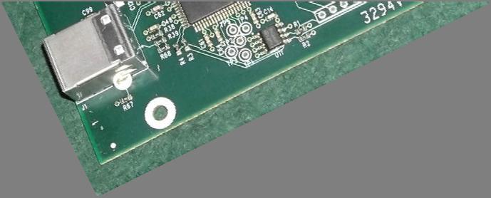
11 4.0 - Hook-up the DATV hardware and Test 4.1 Here is what you need A list of minimum items you need to have your first test of the DATV-Express software and board A version E (or later) DATV-Express exciter A 32-bit or 64-bit PC with appropriate Ubuntu Operating Installed. The faster the CPU, the better. The slowest PC that has been tested is an old Pentium P4 processor running at 1.8 GHz clock. A 12V DC power supply to run the DATV-Express. By itself, the DATV-Express board will run about 2 Watts (mostly quiescent power in the modulator chip U4). A 12V power cable with a xxxx connector at one end to attached to J3 on the hardware board. Invest in purchasing a brand-new USB2 cable with a Type A connector for PC-end, and a Type B connector for the J1 connector on the hardware board. A Hauppauge model PVR-150 or HVR-1950 video-capture card A PAL or NTSC video camera RCA-type cable to connect the connect the camera to the Hauppauge video-capture unit. A Set-Top-Box (STB) connected to some form of display (a TV set or computer) or receiver for the DVB protocol desires. Optionally you can use a spectrum analyzer, if you have access to one. [NOTE optionally I use a microwave directional coupler unit (cheap on e-bay) to split the exciter to both the spectrum analyzer (the forward signal sample) and to the transmitter antenna. A small bent piece of wire to act as a one-quarter-wave vertical antenna for both the DATV-Express exciter board and a second antenna for the DATV STB or stand-alone DATV receiver. RF Amplifiers are optional, but are not needed to checkout if the board and software are working as expected. 4.2 First test power up the DATV-Express board by itself IMPORTANT NOTE please take adequate precautions against ESD discharges to the board. A minimum precaution should be to first touch the 12V DC power supply chassis...or the top of the SMA connector, J2, before you handle the board. Components on an exposed DATV-Express board are susceptible to ESD damage if not handled correctly. NOTE do not connect the USB2 cable to the DATV-Express board at this point of testing. Connect the 12V power cable to J3 on the DATV-Express board Power up the power supply If the LED 4 lights (5.5 V on-board DC-to-DC power supply) near the upper-right mounting hole, then the test is successful No other LEDs on the hardware board should activate during this test. Power off the power supply. 4.3 Second test connect the hardware board and start DATV-Express sw NOTE do NOT connect the Hauppauge video-capture unit during this test Power off the 12V power supply. Connect the USB2 cable between the PC and J1 on the hardware board Power ON the PC After PC boots up, power ON the 12V power supply for the DATV-Express board LED 4 should light (5.5 V on-board DC-to-DC power supply) Double-click on the DATV-Express software application file on the desk top By the time that the GUI window opens up on the PC display, LED 5 and LED 3 should light up and LED 2 should blink if the PC has loaded the FPGA on the hardware board. [ See section 5.13 for LED details.] The normal user display window on the PC should announce DEMO mode as in photo below. 11

12 If the FPGA does not light the new LEDs (LED 5, LED3,and LED2) on the board, that probably means that the code did not download to the board FPGA. Perform a list devices command on the PC (i.e. ls /dev from your home directory) using the TERMINAL box to obtain a list of all devices. The list of devices should show USBxxxx listed 4.4 Third test now connect video-capture to the PC Start by powering OFF the board 12V power supply and the PC Connect the Hauppauge video-capture unit to the PC by an unused USB2 connector Connect the camera cables to the VIDEO and at least one AUDIO jacks on the Hauppauge unit Power ON the camera Power ON the Hauppauge unit (wall-wart?) Power ON the PC When Ubuntu is displaying the desktop, power ON the 12V power supply Double-click on the DATV-Express software application file on the desk top By the time that the GUI window opens up on the PC display, LED 5 and LED 3 should light up and LED 2 should blink if the PC has loaded the FPGA on the hardware board. [ See section 5.13 for LED details.] If everything is working OK at this point, the User window on the PC display should show a message similar to that shown below...not announcing that the software is in the DEMO mode. If everything is OK...then turn OFF power on the 12V power supply, close the DATV-Express software application, and turn OFF power on PC by asking Ubuntu to SHUT DOWN 4.3 Fourth test Transmitting DATV video Choose in your mind, the ham band you want to use, the exact frequency, and DATV protocol (for example: DVB-S or DVB-T) that you want to transmit on. Set up (A) a nearby STB as a receiver for the protocol, and all the DVB settings that the receiver needs to know. Alternatively you could just look on a (B) spectrum analyzer or (C) using an RF splitter or microwave directional-coupler, sample the exciter RF output to the spectrum analyzer and connect the RF output to an antenna to be received by a nearby STB. Figure 8 - a Microwave directional-coupler is used to sample some RF energy for Spectrum Analyzer (shown antenna is for 1.2 GHz band) 12
13 I suggest you will have the best results if you can preprogram the receiver to the channel you plan to transmit on. Blind scans can work to allow the STB to find transmitted DATV signals, but many things can go wrong to cause the STB to not lock on the signal during scanning. The PAT/PMT table sequence is sometimes transmitted in DATV applications NOT often enough. If the STB does NOT pick up that PAT/PMT table information in it s scan dwell period, then the STB will skip to the next channel in the search scan. Place a small bent piece of wire to act as a one-quarter-wave vertical antenna in the SMA connector of the DATV-Express exciter board for the planned transmission band/frequency. If you will be using a nearby-stb or receiver to display the video, then connect another small bent piece of wire to act as a one-quarter-wave vertical antenna for the receiver. Power ON the STB receiver and/or the spectrum analyzer and set it to the desired pre-programmmed channel. Power ON the Hauppauge unit (wall-wart?) and camera Power ON the PC Double-click on the DATV-Express software application file on the desk top By the time that the GUI window opens up on the PC display, LED 5 and LED 3 should light up and LED 2 should blink if the PC has loaded the FPGA on the hardware board. [ See section 5.13 for LED details.] You will need to set-up the DATV-Express software to the exact protocol that you are using. This manual will walk you through a DVB-S test. Other protocols will differ slightly, but you should be able to see the path of a typical set-up by understanding the DVB-S procedure. Go to the TX Tab in the Users window. (See section 5.5) Edit the TRANSMITTER FREQUENCY field in the TX Tab window to the exact center frequency you plan to transmit.for example in the 1.2 GHz band Edit the TRANSMITTER LEVEL field to the RF output level you want to try for example 20 Click on the APPLY button to send these values to the software etc 13
14 5.0 - DATV-Express GUI Reference Guide 5.1 DVB-S Tab Figure 9 Window for the DVB-S Tab Forward Error Correction (FEC) Select the FEC setting that you plan to use on the STB or Receiver from the pull-down menu APPLY Click on the APPLY button when all of the settings have been correctly configured. 14
![5.2 DVB-S2 Tab [Note that the DVB-S2 protocol is not fully tested in this software release.] Figure 10 Window for the DVB-S2 Tab 5.2.1 MODULATION Choose QPSK, 8PSK, 16APSK, or 32APSK modulation technologies from the pull-down menu.](/docs-images/95/125071247/images/15-0.jpg "5.2.2 CODE RATE (FEC) Select the FEC setting that you plan to use on the STB or Receiver from the pull-down menu. 5.2.3 ROLL OFF Etc. 5.2.4 FRAME TYPE Etc. 5.2.5 NULL PACKET DETECTION Etc. 15")
15 5.2 DVB-S2 Tab [Note that the DVB-S2 protocol is not fully tested in this software release.] Figure 10 Window for the DVB-S2 Tab MODULATION Choose QPSK, 8PSK, 16APSK, or 32APSK modulation technologies from the pull-down menu CODE RATE (FEC) Select the FEC setting that you plan to use on the STB or Receiver from the pull-down menu ROLL OFF Etc FRAME TYPE Etc NULL PACKET DETECTION Etc. 15
![5.3 DVB-T Tab [Note that not every feature of the DVB-T protocol implementation has been fully tested.] Figure 11 Window for the DVB-T Tab 5.3.1 MODE The COFDM modulation technology used by the DVB-T](/docs-images/95/125071247/images/16-0.jpg "protocol can be chosen for 1,705 sub-carriers called the 2K packet length mode, or chosen for 6,816 sub-carriers, called the 8K packet length mode.")
16 5.3 DVB-T Tab [Note that not every feature of the DVB-T protocol implementation has been fully tested.] Figure 11 Window for the DVB-T Tab MODE The COFDM modulation technology used by the DVB-T protocol can be chosen for 1,705 sub-carriers called the 2K packet length mode, or chosen for 6,816 sub-carriers, called the 8K packet length mode. Ham radio DATV typically only uses the 2K mode of DVB-T protocol. Select 2K or 8K length of packets from the pull-down menu CONSTELLATION Choose QPSK, 16QAM, or 64QAM modulation technologies from the pull-down menu ALPHA????? (need input from Charles) GUARD PERIOD The purpose of the guard interval is to introduce immunity to propagation delays, echoes and reflections, to which digital data is normally very sensitive. In COFDM, the beginning of each symbol is preceded by a guard interval. As long as the echoes fall within this interval, they will not affect the receiver's ability to safely decode the actual data, as data is only interpreted outside the guard interval. Longer guard periods allow more distant echoes to be tolerated. However, longer guard intervals reduce the channel efficiency FEC RATE Select the FEC setting that you plan to use on the STB or Receiver from the pull-down menu CHANNEL Choose the RF bandwidth of the desired channel that you desire from the pull-down menu. Choose from 8, 7, 6, 4, 3, or 2 MHz bandwidths. 16
17 5.3.7 APPLY Click on the APPLY button when all of the settings have been correctly configured. 17

18 5.4 DVB-T2 Tab (This tab is reserved for future software implementation) 5.5 SR (Symbol-Rate) Tab Figure 12 Window for the Setting Symbol-Rate Symbol Rate (SR) Select the RADIO BUTTON that contains the Symbol Rate that is closest to what you plan to use. You can edit that SR field to the exact Symbol Rate that you plan to use on your STB or Receiver APPLY Click on the APPLY button when all of the settings have been correctly configured. 18
19 5.6 TX Tab Figure 13 Window for the TRANSMITTER Tab TRANSMITTER FREQUENCY Enter the desired frequency for the transmitter. The units in this field are Hz TRANSMITTER LEVEL The DATV-Express hardware board allows values from 0-through-47 to be entered in this field. Each value represents a 1 db difference in the RF output strength. The maximum output of the board s RF buffer amplifier design is somewhere between 10 dbm and 17 dbm. Some boards show a little distortion (spectral regrowth, aka shoulders ) occurring at values higher than APPLY Click on the APPLY button when all of the settings have been correctly configured. 19
20 5.7 PIDs (Packet IDs) Tab Packet ID s (PIDs) play an important role in the DATV Transport Stream (TS). Each table or elementary stream in a transport stream is identified by a 13-bit packet ID (PID). Transport stream specifies a container format encapsulating Packetized Elementary streams, with error correction and stream synchronization features for maintaining transmission integrity when the signal is degraded during DATV terrestrial transmissions. Program streams are created by combining one or more Packetized Elementary Streams (PES), which have a common time base, into a single stream. A Transport Stream may carry multiple programs. Figure 14 Window for PIDs Tab PMT PID The PMT PID is the Packet ID associated with the Program Map Table (PMT). The PMT table contains PID numbers of elementary streams associated with the program and it has information about the type of these elementary streams (video, audio, etc.). The default value is 4095 (decimal). To edit the value, place the cursor inside the PMT PID field, edit the desired value, and press the APPLY button to save the new value VIDEO PID The VIDEO PID is the Packet ID associated with the video Elementary Stream (ES). An ES contains only one kind of data, e.g. audio, video or closed caption. An Elementary Stream is often referred to as "elementary", "data", "audio", or "video" bitstreams or streams. The default value is 256 (decimal). To edit the value, place the cursor inside the VIDEO PID field, edit the desired value, and press the APPLY button AUDIO PID The AUDIO PID is the Packet ID associated with the audio Elementary Stream (ES). An ES contains only one kind of data, e.g. audio, video or closed/data caption. An Elementary Stream is often referred to as "elementary", "data", "audio", or "video" bitstreams or streams. The default value is 257 (decimal). To edit the value, place the cursor inside the AUDIO PID field, edit the desired value, and press the APPLY button PCR PID The PCR PID is the Packet ID associated with the Program Clock Reference (PCR) field. The PCR field enables a decoder to present synchronized content, such as audio tracks matching the associated video, by 20
21 matching up the time-stamps of stream packets. The value of the PCR field, when properly used, is employed to generate a system-timing-clock in the decoder.. The default value is 256 (decimal). To edit the value, place the cursor inside the PCR PID field, edit the desired value, and press the APPLY button DATA PID The DATA PID is the Packet ID associated with the data Elementary Stream (ES). An ES contains only one kind of data, e.g. audio, video or closed/data caption. An Elementary Stream is often referred to as "elementary", "data", "audio", or "video" bitstreams or streams. The default value is 258 (decimal). To edit the value, place the cursor inside the DATA PID field, edit the desired value, and press the APPLY button Typical PID Values There currently is no DATV standard for hams using PID values, yet DATV-Express Recommended PIDs PMT PID 4095 (decimal). VIDEO PID 256 AUDIO PID 257 PCR PID 256 DATA PID BATC Forum DigiLite Suggested PIDs PMT PID 4095 VIDEO PID 256 AUDIO PID 257 PCR PID 333 DATA PID??? APPLY Click on the APPLY button when all of the settings have been correctly configured. 21
22 5.8 SVC (Program) INFO Tab Figure 15 Window for SVC Tab SERVICE PROVIDER NAME The name of the ham station or organization providing the content is entered in this field SERVICE NAME Enter the name you want to apply to the SERVICE NAME that is displayed by the STB into this field APPLY Click on the APPLY button when all of the settings have been correctly configured. 22

23 5.9 EPG (Electronic Program Guide) Tab DVB Electronic Program Guide information typically are available for commercial television transmissions and consist of a digitally displayed, non-interactive menu of broadcast programming scheduling information shown by a satellite TV provider to its viewers on a dedicated channel. The Electronic Program Guide (EPG) feature of DVB transmissions provides receiving DATV stations with the ability to see what programs are planned for the channel they are watching. [Note you should confirm how your STB displays time. A default for STBs appears to be displaying UTC. Edit the UTC offset or enter your local time to achieve the STB displaying your local time.] DURATION (MINS) Field Figure 16 Window for EPG Tab The DURATION field sets the times shown for an EVENT in the GUIDE (EPG) listing shown by the STB. The staring time for the event will be when you started the DATV-Express software. The ending time shown for the EVENT listing will be (starting time + DURATION). The DURATION setting has no effect on the actual transmissions of the RF just the information displayed in EPG by the STB EVENT TITLE This field allows you to enter a title name that will appear in the displayed EPG on the STB when your transmission is tuned in. You could enter TITLEs such as: CLUB NET W6HHC Test Pattern Field Day Video Etc EVENT Text This field allows you to enter more detailed descriptive text in the displayed EPG on the STB when your transmission is tuned in. For example the text could say: 2013 OCARC club FD was held in the city of Buena Park APPLY Click on the APPLY button when all of the settings have been correctly configured. 23

24 5.10 HW (HARDWARE) Tab VIDEO CAPTURE DEVICE Figure 17 Window for the HARDWARE Tab This field is intended to identify your video capture card for the DATV-Express board. The Ubuntu operating system will probably default to Dev 0 device number which may be a web camera, etc. Use the pull-down menu to find the video-capture card you want to use. In Figure 17, the WinTV HVR-1950 Model 751zz driver is being correctly displayed. If needed, you can perform a list devices command (i.e. ls /dev from your home directory) using the Ubuntu TERMINAL box to obtain a list of all devices. If the wrong video device is selected here, you will most likely see Demo Mode and CAP errors (video capture errors and audio capture errors) listed in the MAIN window message area CAPTURE DEVICE TYPE This pull-down menu allows you to choose among PVRXXX, and PVRHD, and UDP TS selections. PVRXXX is the correct selection if you are using the Hauppauge PVR-150, PVR350 (dual channel version of the PVR250), PVRUSB2, HVR-1900, or HVR-1950 video-capture units. This selection will automatically choose between NTSC and PAL cameras being used. PVRHD is the correct selection if you are using a High Definition (HD) model of Hauppauge videocapture unit. UDP TS selects the video input source from a UDP transport stream on the PC INPUT SELECTOR Selects the port on the Hauppauge device composite input, TV input. Normally this is set to one for the camera. 0 = Tuner input 1 = Composite input 2 = S-Video input TRANSMITTER The pull-down menu allows you to choose between EXPRESS 16-bit, EXPRESS-8-bit, and EXPRESS TS selections. EXPRESS 16-bit provides IQ samples is normally selected and is the default value. EXPRESS 8-bit IQ samples can be selected to reduce the load on the USB interface by 50% and is good enough for DVB-S and DVB-S2 24
25 EXPRESS TS is currently reserved for a future feature. Eventually, the FPGA chip coding on the DATV- Express board will do the entire DVB-S encoding function (for the non-pc version). At that point, the board will require a Transport Stream rather than a sample IQ stream for the transmitter to use as input ENABLE CALIBRATION (Checkbox) This check box enables the DAC OFFSET adjustment below. The CARRIER SUPPRESSION feature requires an external narrow band receiver (for example FM), or spectrum analyzer, or an external directional-coupler that is connected to the board RF output and sampling a rectified signal back to connector J4, pins 11 and CARRIER SUPPRESSION ADJUSTMENT Differences in component values used in the I stream can be slightly than those in the Q stream, and also the gains between the I gain and the Q gain in the modulator IC can have differences. These differences can result in an unwanted carrier being transmitted (rather than suppressed). By adjusting the DAC OFFSET, the differences can be minimized. 1) it does not matter what mode is set on MAIN Tab 2) Go to Hardware Tab and select ENABLE CALIBRATION check box and the DAC GAIN checkbox. As soon as you select ENABLE CALIBRATION checkbox, the board goes into calibrate mode, there is NO NEED to click APPLY or use the PTT. 3) Tune a nearby NB receiver (e.g. FM) or a spectrum analyzer to the frequency set in MAIN Tab 4) Measure the S-meter signal strength of the carrier?? 5) Adjust the DAC GAIN settings a bit...hit APPLY(?) and observe change in signal level on the receiver 6) Repeat step 5 until you obtain the lowest signal strength on the receiver. 7) When you uncheck the ENABLE CALIBRATION check box, the calibration values are saved SERVER IP ADDRESS The DATV-Express software has a built-in server that waits for network input from a client that can provide a Transport Stream (TS). The SERVER IP ADDRESS field allows you to select the IP address that you want the server to operate on to work across a network SOCKET NUMBER This field allows you to enter the socket number you want to associate with the SERVER IP ADDRESS in order to send a TS to the board APPLY Click on the APPLY button when all of the settings have been correctly configured. 25

26 5.11 MODE Tab Figure 18 Window for the MODE Tab DVB MODE This pull-down menu currently allows you to select either DVB-S, DVB-S2, or DVB-T protocols APPLY Click on the APPLY button when all of the settings have been correctly configured. 26

 5.12.1 TRANSMIT QUEUE 5.12.2 NULLS INSERTED 5.12.3 TRANSMIT DELAY Etc.")
27 5.12 MAIN Tab The MAIN window is where you will operate your transmitter once all of the modes and configurations have been set-up in other GUI windows. The MAIN window displays the set-up values, provides a PTT button as well as has a message window. Figure 19 Message area of MAIN display showing normal running Figure 20 Message area of MAIN display showing error-condition messages (The Video-Capture card is not plugged into USB port.) TRANSMIT QUEUE NULLS INSERTED TRANSMIT DELAY Etc. 27

28 CARRIER (Checkbox) Etc TS LOG TO FILE (Checkbox) Whenever this check box is clicked, the DATV-Express software immediately begins to capture the Transport Stream (TS) to a disk drive.ts file. The TS file will be logged independent of the PTT function. The.ts file is called datvexpress.ts and will be found in your computer HOME directory. Figure nn The Latest TS file will be stored in the HOME directory I suggest renaming the.ts file immediately to something like datvexpress_g4xyz_4msym.ts, so the file will not be overwritten the next time you use the TS LOG. The file can then be moved or copied to your desktop. You can watch the TS file played back using a program like VLC on Ubuntu or Windows Media Player on Windows. The details of the TS file can be inspected using an analyzer like DVBinpector (free) PTT (Button) Etc. 28
29 5.13 Board LEDs LED V Power supply is operational (upper right-hand corner near mounting hole) LED 5 quickly blinks and then turns ON? (1'b1) LED 1 blinks quickly when there is activity with I2C interface on the board LED 2 Sample clock constantly blinks to show that FPGA is running (cnt_r[25]) LED 3 PLL Lock 29
30 6.0 - Useful utilities DVBinspector 1. Use VLC as TS player on Ubuntu 2. Use Windows Media Player as TS player on Win7 CPU performance monitor Tutioune DVB-S analyzer DATV-Express specs 30
DATV-Express Users Guide. (based on DATV-Express software release v2.01) Draft 32
 Draft 32") DATV-Express Users Guide (based on DATV-Express software release v2.01) Draft 32 1 Table of Contents 1.0 Introduction... 5 2.0 Prepare Disk Drive on PC... 5 2.1 Just reformat and devote the entire single
DATV-Express Users Guide (based on DATV-Express software release v2.01) Draft 32 1 Table of Contents 1.0 Introduction... 5 2.0 Prepare Disk Drive on PC... 5 2.1 Just reformat and devote the entire single
DATV-Express Users Guide For running on Windows OS. (based on Express_DVB-S/-S2/-T_Transmitter software v1.23-beta) Draft 010
 Draft 010") DATV-Express Users Guide For running on Windows OS (based on Express_DVB-S/-S2/-T_Transmitter software v1.23-beta) Draft 010 1 Table of Contents 1.0 Introduction... 6 2.0 Install Express_DVB S/ S2_Transmitter
DATV-Express Users Guide For running on Windows OS (based on Express_DVB-S/-S2/-T_Transmitter software v1.23-beta) Draft 010 1 Table of Contents 1.0 Introduction... 6 2.0 Install Express_DVB S/ S2_Transmitter
DATV-Express Users Guide For running on Windows OS. (based on Express_DVB _Transmitter software v1.25lp11) Draft 14
 Draft 14") DATV-Express Users Guide For running on Windows OS (based on Express_DVB _Transmitter software v1.25lp11) Draft 14 1 Table of Contents 1.0 Introduction... 5 2.0 Install Express_DVB_Transmitter software
DATV-Express Users Guide For running on Windows OS (based on Express_DVB _Transmitter software v1.25lp11) Draft 14 1 Table of Contents 1.0 Introduction... 5 2.0 Install Express_DVB_Transmitter software
AVE HOME FAGOR CVBS TO DVB-T ENCODER MODULATOR. Fagor Electr6nica
 AVE HOME CVBS TO DVB-T ENCODER MODULATOR FAGOR Fagor Electr6nica TABLE OF CONTENTS 1. SPECIFICATIONS... 12 1.1 Product Overview... 12 1.2 Appearance and Description... 12 1.3 Diagram... 13 1.4 Characteristics...
TV4U QUAD DVB-S2 to DVB-C TRANSMODULATOR
 INSTRUCTION MANUAL Features of the new DVB-C transmodulators line Through the use of the FPGA technology the transmodulators provides the highest performance at the lowest price. Four carriers are formed
Operation and Installation Guide
 Operation and Installation Guide HDS2800 Series Encoder Modulator High Definition (HD) Digital COFDM MPEG2 and H.264 Modulator with IP Multicast. 19 Rack Mount Revision 4.0 Firmware version Released File
HD4112 Quad HDMI MPEG2 HD DVBT Encoder Modulator U S E R M A N U A L
 HD4112 Quad HDMI MPEG2 HD DVBT Encoder Modulator U S E R M A N U A L HD4112 Manual Rev 1 Contents 1. GENERAL 1.1 Description 1.2 Specifications 2. INSTALLATION 2.1 What s in the Box 2.2 Connection 2.2.1
TechTalk123 - The MiniTiouner Receiver/Analyzer for Digital-ATV
 TechTalk123 - The MiniTiouner Receiver/Analyzer for Digital-ATV by Ken W6HHC Jean-Pierre F6DZP has been modifying Digital-ATV receivers for DVB-S protocol with software for years - in order to allow the
AMD-53-C TWIN MODULATOR / MULTIPLEXER AMD-53-C DVB-C MODULATOR / MULTIPLEXER INSTRUCTION MANUAL
 AMD-53-C DVB-C MODULATOR / MULTIPLEXER INSTRUCTION MANUAL HEADEND SYSTEM H.264 TRANSCODING_DVB-S2/CABLE/_TROPHY HEADEND is the most convient and versatile for digital multichannel satellite&cable solution.
Operation and Installation Guide
 Operation and Installation Guide HDS2800 Series Encoder Modulator High Definition (HD) Digital COFDM MPEG2 and H.264 Modulator with IP Multicast. 19 Rack Mount Wall Mount Revision 0.1 Firmware version
HV-122-DCA DVB-T 2-Way Diversity Receiver Box Quick Installation Guide
 HV-122-DCA DVB-T 2-Way Diversity Receiver Box Quick Installation Guide PACKAGE CONTENTS 4 FRONT PANEL VIEW 4 BACK PANEL VIEW 4 BOARD VIEW 5 IR REMOTE CONTROLLER-TYPE A 6 FILL BATTERY TO IR CONTROLLERS:
INSTALLATION AND OPERATION INSTRUCTIONS EVOLUTION VIDEO DISTRIBUTION SYSTEM
 INSTALLATION AND OPERATION INSTRUCTIONS EVOLUTION VIDEO DISTRIBUTION SYSTEM ATTENTION: READ THE ENTIRE INSTRUCTION SHEET BEFORE STARTING THE INSTALLATION PROCESS. WARNING! Do not begin to install your
2013 ARRL/TAPR DCC. DATV-Express
 2013 ARRL/TAPR DCC a Testing Report by Art Towslee towslee1@ee.net Ken Konechy W6HHC@ARRL.net WA8RMC W6HHC The Presentation Authors. Art WA8RMC Ken W6HHC 2 103 Status of Digital-ATV Today Video Quality
VIDEO GRABBER. DisplayPort. User Manual
 VIDEO GRABBER DisplayPort User Manual Version Date Description Author 1.0 2016.03.02 New document MM 1.1 2016.11.02 Revised to match 1.5 device firmware version MM 1.2 2019.11.28 Drawings changes MM 2
Update on DATV-Express exciter for Digital-ATV
 2015 ARRL/TAPR DCC by Update on DATV-Express exciter for Digital-ATV Ken Konechy W6HHC W6HHC@ARRL.net Abstract - The old technology of analog-atv suffers from susceptibility to snow and multi-path ghost
Laboratory stand description. Investigation of DVB-T/C/IPTV technologies
 1 Laboratory stand description Investigation of DVB-T/C/IPTV technologies Table of Contents 1. Hardware prerequisites... 3 1.1 Hardware parts... 3 1.2 Cables required for system interconnection... 5 1.3
DC-105 Quick Installation Guide
 DC-105 Quick Installation Guide PACKAGE CONTENTS 2 POWER ON 2 CONNECT TO A DVB-T RECEIVER 3 ADJUST THE FOCUS OF THE LENS 3 CONNECT TO A CVBS MONITOR 4 MIC-IN 4 USB UART DONGLE 5 MONITOR BOOT MESSAGES 7
2011 ARRL TAPR Digital Comm Conference
 2011 ARRL TAPR Digital Comm Conference by Charles Brain G4GUO@ARRL.net Ken Konechy W6HHC@ARRL.net G4GUO W6HHC Status of Digital-ATV Today Video Quality of DATV far exceeds analog-atv Very few hams transmitting
Wireless Studio. User s Guide Version 5.1x Before using this software, please read this manual thoroughly and retain it for future reference.
 4-743-161-12 (1) Wireless Studio User s Guide Version 5.1x Before using this software, please read this manual thoroughly and retain it for future reference. DWR-R01D/R02D/R02DN/R03D 2018 Sony Corporation
DVB-T USB SET-TOP BOX
 DVB-T USB SET-TOP BOX User Manual Version: 1.0 (February 2005) TRANSYSTEM INC. No.1-2 Li-Hsin Rd.I Science-Based Industrial Park, Hsinchu, Taiwan Tel:+886-3-5780393 Fax:+886-3-5784111 e-mail: sales@transystem.com.tw
SD4650 DVB-T HD MODULATOR. User Manual
 SD4650 DVB-T HD MODULATOR User Manual 0 TABLE OF CONTENT 1 GENERAL...2 1.1 Description...2 1.2 Specifications...3 2 INSTALLATION...4 2.1 What s in the Box...4 One power cable...4 2.2 Connection...4 2.2.1
HD-1603 Single Input MPEG-4 DVB-T HD Encoder/Modulator User Guide and Install Manual
 ZyCastR digi-mod HD Range digi-mod HD-1603 www.digi-modbyzycast.com HD-1603 Single Input MPEG-4 DVB-T HD Encoder/Modulator User Guide and Install Manual Table of Contents www.digi-modbyzycast.com Safety
AT780PCI. Digital Video Interfacing Products. Multi-standard DVB-T2/T/C Receiver & Recorder & TS Player DVB-ASI & DVB-SPI outputs
 Digital Video Interfacing Products AT780PCI Multi-standard DVB-T2/T/C Receiver & Recorder & TS Player DVB-ASI & DVB-SPI outputs Standard Features - PCI 2.2, 32 bit, 33/66MHz 3.3V. - Bus Master DMA, Scatter
Table of Contents. 1. Safety Use. 2. General Description. 3. Connection Diagram. 4. Operations and Management. 4.1 Display Status. 4.
 DTM-HD01 Thank you for buying this encoder modulator. Please read this manual carefully to install, use and maintain the encoder modulator in the best conditions of performance. Keep this manual for future
ToshibaEdit. Contents:
 ToshibaEdit Contents: 1 General 2 Installation 3 Step by step a Load and back up a settings file b Arrange settings c Provider d The favourite lists e Channel parameters f Write settings into the receiver
Digital single HDMI Modulator to DVB-T/MPEG4. User s Guide
 Digital single HDMI Modulator to DVB-T/MPEG4 User s Guide Contents INTRODUCTION... 3 FEATURES... 3 Technical Specifications... 4 RF Specifications... 4 CONNECTIΟΝ & OPERATION... 5 PACKAGE INCLUDES... 5
USB Mini Spectrum Analyzer User s Guide TSA5G35
 USB Mini Spectrum Analyzer User s Guide TSA5G35 Triarchy Technologies, Corp. Page 1 of 21 USB Mini Spectrum Analyzer User s Guide Copyright Notice Copyright 2011 Triarchy Technologies, Corp. All rights
User manual Transmodulators. Ref. 5103S/5103T/5103Q/5130
 User manual Transmodulators Ref. 5103S/5103T/5103Q/5130 Contents 1 Introduction 2 1.1 The ProQuad range................................ 2 1.2 Modular system solution.............................. 4 1.3
FlyTV Express M5 MST-T 2 A 2
 FlyTV Express M5 MST-T 2 A 2 User Manual Animation Technologies Inc. www.lifeview.com Ver: 1.0 Copyright and Trademark Notice 2006 by Animation Technologies Inc. All rights reserved. Information in this
D-Lab & D-Lab Control Plan. Measure. Analyse. User Manual
 D-Lab & D-Lab Control Plan. Measure. Analyse User Manual Valid for D-Lab Versions 2.0 and 2.1 September 2011 Contents Contents 1 Initial Steps... 6 1.1 Scope of Supply... 6 1.1.1 Optional Upgrades... 6
Notes on Using Hi-Des DVB-T Products with KH6HTV Video -- RF Linear Power Amplifiers Jim Andrews, KH6HTV
 AN-18 HiDesNotes.doc (kh6htv, rev. 10/30/14) p. 1 of 9 Application Note AN-18 copyright - Sept, 2014 Revised - Oct. 2014 Notes on Using Hi-Des DVB-T Products with KH6HTV Video -- RF Linear Power Amplifiers
VideoMate U3 Digital Terrestrial USB 2.0 TV Box Start Up Guide
 VideoMate U3 Digital Terrestrial USB 2.0 TV Box Start Up Guide Compro Technology, Inc. www.comprousa.com Copyright 2001-2005. Compro Technology, Inc. No part of this document may be copied or reproduced
TVW750USBD ATSC Tuner Quick install manual
 Getting Started TVW750USBD ATSC Tuner Quick install manual The Diamond TVW750USBD ATSC Tuner is fully compatible for your Windows desktop PC or laptop. Important Notice: All channels are subject to coverage
Teletext Inserter Firmware. User s Manual. Contents
 Teletext Inserter Firmware User s Manual Contents 0 Definition 3 1 Frontpanel 3 1.1 Status Screen.............. 3 1.2 Configuration Menu........... 4 2 Controlling the Teletext Inserter via RS232 4 2.1
Scan Converter Installation Guide
 Scan Converter Installation Guide Software on supplied disks Please note: The software included with your scan converter is OPTIONAL. It is not needed to make the scan converter work properly. This software
SNG-2150C User s Guide
 SNG-2150C User s Guide Avcom of Virginia SNG-2150C User s Guide 7730 Whitepine Road Revision 001 Richmond, VA 23237 USA GENERAL SAFETY If one or more components of your earth station are connected to 120
TV4U DVB-S2 to DVB-S2 TRANSMODULATOR
 TV4U to TRANSMODULATOR TV4U to TRANSMODULATOR INSTRUTION MANUAL TV4U to TRANSMODULATOR The main application of to transmodulator Experience of MVDS terrestrial broadcasting shows that carrier must be restored
User s Guide W-E
 Presto! PVR ISDB User s Guide 518100-02-01-W-E-112307-02 Copyright 2007, NewSoft Technology Corp. All Rights Reserved. No portion of this document may be copied or reproduced in any manner without prior
Portable TV Meter (LCD) USER S MANUAL
 USER S MANUAL") 1 Portable TV Meter User Manual (LCD) Portable TV Meter (LCD) USER S MANUAL www.kvarta.net 1 / 19 2 Portable TV Meter User Manual (LCD) Contents 1. INTRODUCTION... 3 1.1. About KVARTA... 3 1.2. About DVB...
1 Portable TV Meter User Manual (LCD) Portable TV Meter (LCD) USER S MANUAL www.kvarta.net 1 / 19 2 Portable TV Meter User Manual (LCD) Contents 1. INTRODUCTION... 3 1.1. About KVARTA... 3 1.2. About DVB...
HD168Bi Quad CVBS/HDMI HD DVBT Encoder Modulator U S E R M A N U A L
 HD168Bi Quad CVBS/HDMI HD DVBT Encoder Modulator U S E R M A N U A L Contents 1. GENERAL 1.1 Description 1.2 Specifications 2. INSTALLATION 2.1 What s in the Box 2.2 Connection 2.2.1 DEVICE Programming
DXI-800 DVB-S/S2/T to IP streamer User Manual
 DXI-800 DVB-S/S2/T to IP streamer User Manual 1. Purpose of use DXI-800 is HD compatible IP streamer designed for a processing satellite and terrestrial signals to data broadcast (IP) connected to Ethernet.
Installation & Operational Manual
 Radiant Communications Corporation 5001 Hadley Road South Plainfield NJ 07080 Tel (908) 757-7444 Fax (908) 757-8666 WWW.RCCFIBER.COM QRF5000M MDU ENCODER Installation & Operational Manual Rev.A2 1. Introduction
Manual of Operation for WaveNode Model WN-2m. Revision 1.0
 Manual of Operation for WaveNode Model WN-2m. Revision 1.0 TABLE OF CONTENTS 1. Description of Operation 2. Features 3. Installation and Checkout 4. Graphical Menus 5. Information for Software Expansion
The Kaffeine Handbook. Jürgen Kofler Christophe Thommeret Mauro Carvalho Chehab
 Jürgen Kofler Christophe Thommeret Mauro Carvalho Chehab 2 Contents 1 Kaffeine Player 5 1.1 The Start Window...................................... 5 1.2 Play a File..........................................
USB Mini Spectrum Analyzer User Manual TSA Program for PC TSA4G1 TSA6G1 TSA8G1
 USB Mini Spectrum Analyzer User Manual TSA Program for PC TSA4G1 TSA6G1 TSA8G1 Triarchy Technologies Corp. Page 1 of 17 USB Mini Spectrum Analyzer User Manual Copyright Notice Copyright 2013 Triarchy Technologies,
AT2780USB. Digital Video Interfacing Products. DVB-T/H/C & ATSC Modulator IF and RF ( VHF & UHF ) Output DVB-ASI & DVB-SPI Inputs
 Output DVB-ASI & DVB-SPI Inputs") Digital Video Interfacing Products AT2780USB DVB-T/H/C & ATSC Modulator IF and RF ( VHF & UHF ) Output DVB-ASI & DVB-SPI Inputs Standard Features DVB-T/H/C Modulator with VHF & UHF Up converter. - High
Digital Video Interfacing Products AT2780USB DVB-T/H/C & ATSC Modulator IF and RF ( VHF & UHF ) Output DVB-ASI & DVB-SPI Inputs Standard Features DVB-T/H/C Modulator with VHF & UHF Up converter. - High
Ultra-ViewRF 8HD Director Monitor. User Operation Manual
 Ultra-ViewRF 8HD 5.8GHz Wireless Director Monitor User Operation Manual 17.1.2013 v2_7 Video Equipment Rentals - VER 912 Ruberta Avenue Glendale, CA 91201 - U.S.A. Office 818-956-1444 Table of Contents
VDT-100 User Manual 1
 VDT-100 User Manual 1 Copyright Notice The use manual, including all its contents, is copyrighted by Videa Technology Inc.. All rights are reserved. Videa Technology Inc. reserves the right to improve
STM 26 HD. DVB-S2+T2/C Compact meter User Manual. Ref R13. CAHORS Digital CS Cahors Cedex 9 FRANCE
 STM 26 HD DVB-S2+T2/C Compact meter User Manual Ref 0145225R13 Preface USER MANUAL Please read this manual carefully before using your Digital Sat meter for the first time. This operating manual will help
Quick installation and configuration guide STC
 Quick installation and configuration guide STC 200 REF. 4466 Contents 4 Introduction 4 General description 5 General use of the headend 6 Initial installation and configuration 6 Assembly, connection
SPECIFICATION. DVB-T / Worldwide NIM Tuner
 1.Feature * DVB-T demodulator for COFDM with excellent multipath performance, meeting: * DVB-T Digital Television Standard ETS 300744 * Nordig-Unified v1.0.3 Receiver Specification 2.Applications * Digital
USB Mini Spectrum Analyzer User Manual PC program TSA For TSA5G35 TSA4G1 TSA6G1 TSA12G5
 USB Mini Spectrum Analyzer User Manual PC program TSA For TSA5G35 TSA4G1 TSA6G1 TSA12G5 Triarchy Technologies, Corp. Page 1 of 17 USB Mini Spectrum Analyzer User Manual Copyright Notice Copyright 2013
HD RANGER+ Evolution? NO. Revolution!
 Evolution? NO. Revolution! The SIXTH GENERATION field meter FROM PROMAX lite ACTUAL SIZE - 7 SCREEN (APPROX. 155 x 93 mm) Revolutionising the market. Again The largest and brightest display HD RANGER+
CompactMax-2 DVB-S/S2 TO DVB-T2 TRANSMODULATOR - 0 MI2100 -
 CompactMax-2 DVB-S/S2 TO DVB-T2 TRANSMODULATOR - 0 MI2100 - SAFETY NOTES Read the user s manual before using the equipment, mainly "SAFETY RULES" paragraph. The symbol on the equipment means "SEE USER
HD PVR MCE Support Release Notes Version /28/2010
 HD PVR MCE Support Release Notes Version 1.1.28271 9/28/2010 The HD PVR support for Windows Media Center allows you to use the HD PVR to watch, pause and record high definition TV under Windows 7 Media
QRF5000 MDU ENCODER AND QAM MODULATOR
 Radiant Communications Corporation 5001 Hadley Road South Plainfield NJ 07080 Tel (908) 757-7444 Fax (908) 757-8666 WWW.RCCFIBER.COM QRF5000 MDU ENCODER AND QAM MODULATOR Installation & Operational Manual
DVB-S. User s manual
 DVB-S User s manual DVB-S Introduction 1.1 product Introduction DVB-S can implement IP data decoding and MPEG-2 A/V decoding. DVB-S can be widely used in software download, fast accessing internet, distance
AT720USB. Digital Video Interfacing Products. DVB-C (QAM-B, 8VSB) Input Receiver & Recorder & TS Player DVB-ASI & DVB-SPI outputs
 Input Receiver & Recorder & TS Player DVB-ASI & DVB-SPI outputs") Digital Video Interfacing Products AT720USB DVB-C (QAM-B, 8VSB) Input Receiver & Recorder & TS Player DVB-ASI & DVB-SPI outputs Standard Features - High Speed USB 2.0. - Windows XP, Vista, Win 7 ( 64bit
Digital Video Interfacing Products AT720USB DVB-C (QAM-B, 8VSB) Input Receiver & Recorder & TS Player DVB-ASI & DVB-SPI outputs Standard Features - High Speed USB 2.0. - Windows XP, Vista, Win 7 ( 64bit
AT660PCI. Digital Video Interfacing Products. DVB-S2/S (QPSK) Satellite Receiver & Recorder & TS Player DVB-ASI & DVB-SPI outputs
 Satellite Receiver & Recorder & TS Player DVB-ASI & DVB-SPI outputs") Digital Video Interfacing Products AT660PCI DVB-S2/S (QPSK) Satellite Receiver & Recorder & TS Player DVB-ASI & DVB-SPI outputs Standard Features - PCI 2.2, 32 bit, 33/66MHz 3.3V. - Bus Master DMA, Scatter
Digital Video Interfacing Products AT660PCI DVB-S2/S (QPSK) Satellite Receiver & Recorder & TS Player DVB-ASI & DVB-SPI outputs Standard Features - PCI 2.2, 32 bit, 33/66MHz 3.3V. - Bus Master DMA, Scatter
SingMai Electronics SM06. Advanced Composite Video Interface: HD-SDI to acvi converter module. User Manual. Revision 0.
 SM06 Advanced Composite Video Interface: HD-SDI to acvi converter module User Manual Revision 0.4 1 st May 2017 Page 1 of 26 Revision History Date Revisions Version 17-07-2016 First Draft. 0.1 28-08-2016
ir32 installation files for IR receive and blaster functionality. mce the HD PVR MCE Support installer (setup.exe)
") HD PVR \ Colossus Media Center Support Release Notes Version 1.1.29178 6/27/2011 Support for Windows Media Center allows you to use one HD PVR or Colossus to watch, pause and record high definition TV
HD PVR \ Colossus Media Center Support Release Notes Version 1.1.29178 6/27/2011 Support for Windows Media Center allows you to use one HD PVR or Colossus to watch, pause and record high definition TV
DVR-431 USB Wireless Receiver User Manual
 DVR-431 USB Wireless Receiver User Manual Thank you for using our wireless USB receiver, please read the following content carefully before using, it will help you make better use of this product. Introduction
HiPix DTV-200 HDTV MultiMedia Control Card for your PC. Users Manual
 HiPix DTV-200 HDTV MultiMedia Control Card for your PC Users Manual Version 1.2 June, 2001 TELEMANN HIPIX DTV-200 SOFTWARE END-USER LICENSE This is a legally relevant License (the "License") between Global
HEVC H.265 TV ANALYSER
 INTRODUCING THE WORLD S FIRST HEVC H.265 METER & TV ANALYSER Digital terrestrial TV is at the dawn of a new transformation driven by the need to release yet further spectrum in the so called second dividend
CI-218 / CI-303 / CI430
 CI-218 / CI-303 / CI430 Network Camera User Manual English AREC Inc. All Rights Reserved 2017. l www.arec.com All information contained in this document is Proprietary Table of Contents 1. Overview 1.1
Mobile DTV Viewer. User Manual. Mobile DTV ATSC-M/H DVB-H 1Seg. Digital TV ATSC DVB-T, DVB-T2 ISDB-T V 4. decontis GmbH Sachsenstr.
 Mobile DTV ATSC-M/H DVB-H 1Seg Digital TV ATSC DVB-T, DVB-T2 ISDB-T V 4 decontis GmbH Sachsenstr. 8 02708 Löbau Germany +49 3585 862915 +49 3585 415629 www.com dvbsam@com 1 Introduction... 5 2 System Requirements...
MyM-3S Micro Master. Installation Guide. English. design for TV
 MyM-3S Micro Master Installation Guide design for TV 1 CONTENT 1. Introduction 2. Unpacking the unit 3. Connections and indications 4. IP settings 5. Menus and settings 5.1 Overview menu 5.2 Input settings
QRF5000 MDU ENCODER. Data Sheet
 Radiant Communications Corporation 5001 Hadley Road South Plainfield NJ 07080 Tel (908) 757-7444 Fax (908) 757-8666 WWW.RCCFIBER.COM QRF5000 MDU ENCODER Data Sheet Version 1.1 1 Caution Verify proper grounding
A LOW COST TRANSPORT STREAM (TS) GENERATOR USED IN DIGITAL VIDEO BROADCASTING EQUIPMENT MEASUREMENTS
 GENERATOR USED IN DIGITAL VIDEO BROADCASTING EQUIPMENT MEASUREMENTS") A LOW COST TRANSPORT STREAM (TS) GENERATOR USED IN DIGITAL VIDEO BROADCASTING EQUIPMENT MEASUREMENTS Radu Arsinte Technical University Cluj-Napoca, Faculty of Electronics and Telecommunication, Communication
A LOW COST TRANSPORT STREAM (TS) GENERATOR USED IN DIGITAL VIDEO BROADCASTING EQUIPMENT MEASUREMENTS Radu Arsinte Technical University Cluj-Napoca, Faculty of Electronics and Telecommunication, Communication
Simple Media Platform Quick Installation Guide V1.0-N. Simple Media Platform. Quick Installation Guide
 Simple Media Platform Quick Installation Guide 1. Installation Instruction 1.1 Mounting unit to a 19 rack When selecting the installation site, try to comply with the following: Protective Ground - The
Broadcast Satellite Modulator
 M6100 Modulator Broadcast Satellite Modulator The M6100 Broadcast Satellite Modulator is the latest generation satellite modulator built from the ground up for contribution, distribution and direct-to-home
AT278USB, imod. Digital Video Interfacing Products. DVB-T/H/C & ATSC Modulator IF and RF ( VHF & UHF ) Output DVB-ASI Input
 Output DVB-ASI Input") Digital Video Interfacing Products AT278USB, imod DVB-T/H/C & ATSC Modulator IF and RF ( VHF & UHF ) Output DVB-ASI Input Standard Features DVB-T/H/C Modulator with VHF & UHF Up converter. - High Speed
Digital Video Interfacing Products AT278USB, imod DVB-T/H/C & ATSC Modulator IF and RF ( VHF & UHF ) Output DVB-ASI Input Standard Features DVB-T/H/C Modulator with VHF & UHF Up converter. - High Speed
user manual Colosseum 8500D
 user manual Colosseum 8500D No part of this manual may be copied, reproduced, transmitted, transcribed or translated into any language without permission. Unitron reserves the right to change the specifications
DVB-T Hybrid X8000T. PCI Card
 176149 DVB-T Hybrid X8000T PCI Card User Manual Ver: 1.0 Contents 1. Getting Started... 1 1.1 Introduction...1 1.2 Features...1 1.3 Package Contents...1 1.4 System Requirements...2 2. Input & Output Connections...
Single & Dual Input HD Digital DVB-T Modulators
 Radio Frequency Range Installation Diagram digi-mod HD-1000DM / HD-2000DM www.resi-linx.com Single & Dual Input HD Digital DVB-T Modulators ANT IN 1 2 3 4 AUX MOD RF IN TV OUTPUTS MOD RF IN (PWR/IR PASS)
B. The specified product shall be manufactured by a firm whose quality system is in compliance with the I.S./ISO 9001/EN 29001, QUALITY SYSTEM.
 VideoJet 8000 8-Channel, MPEG-2 Encoder ARCHITECTURAL AND ENGINEERING SPECIFICATION Section 282313 Closed Circuit Video Surveillance Systems PART 2 PRODUCTS 2.01 MANUFACTURER A. Bosch Security Systems
NanoGiant Oscilloscope/Function-Generator Program. Getting Started
 Getting Started Page 1 of 17 NanoGiant Oscilloscope/Function-Generator Program Getting Started This NanoGiant Oscilloscope program gives you a small impression of the capabilities of the NanoGiant multi-purpose
LedSet User s Manual V Official website: 1 /
 LedSet User s Manual V2.6.1 1 / 42 20171123 Contents 1. Interface... 3 1.1. Option Menu... 4 1.1.1. Screen Configuration... 4 1.1.1.1. Instruction to Sender/ Receiver/ Display Connection... 4 1.1.1.2.
HD-1600 Single Input MPEG-4 DVB-T HD Encoder/Modulator User Guide and Install Manual
 digi-mod HD Range digi-mod HD-1600 www.resi-linx.com HD-1600 Single Input MPEG-4 DVB-T HD Encoder/Modulator User Guide and Install Manual Table of Contents Safety Precautions 2 Package Contents 2 Product
RANGERNeo + TV, CABLE, SATELLITE & WIFI ANALYSER HEVC H.265 EASY OPERATION WIFI ANALYSER WIDEBAND LNB A NEW STANDARD IN FIELD STRENGTH METERS
 A NEW STANDARD IN FIELD STRENGTH METERS TV, CABLE, SATELLITE & WIFI ANALYSER RANGERNeo + EASY OPERATION HEVC H.265 WIFI ANALYSER WIDEBAND LNB Hybrid user interface (touch + keyboard) High Efficiency Video
APM CALIBRATION PROCEDURE Rev. A June 3, 2015
 APM CALIBRATION PROCEDURE Rev. A June 3, 2015 Calibration of the APM allows system parameters such as coupler coupling values, interconnecting cable losses and system feeder losses to be programmed into
Booya16 SDR Datasheet
 Booya16 SDR Radio Receiver Description The Booya16 SDR radio receiver samples RF signals at 16MHz with 14 bits and streams the sampled signal into PC memory continuously in real time. The Booya software
CompactMax-4 DVB-S/S2 TO ISDB-T TRANSMODULATOR - 0 MI2101 -
 CompactMax-4 DVB-S/S2 TO ISDB-T TRANSMODULATOR - 0 MI2101 - SAFETY NOTES Read the user s manual before using the equipment, mainly "SAFETY RULES" paragraph. The symbol on the equipment means "SEE USER
invr User s Guide Rev 1.4 (Aug. 2004)
") Contents Contents... 2 1. Program Installation... 4 2. Overview... 4 3. Top Level Menu... 4 3.1 Display Window... 9 3.1.1 Channel Status Indicator Area... 9 3.1.2. Quick Control Menu... 10 4. Detailed
Contents Contents... 2 1. Program Installation... 4 2. Overview... 4 3. Top Level Menu... 4 3.1 Display Window... 9 3.1.1 Channel Status Indicator Area... 9 3.1.2. Quick Control Menu... 10 4. Detailed
English CONTENTS 1. GUIDE FEATURES THE MENU OSD INSTRUCTION TECHNICAL SPECIFICATION... 7
 USER S MANUAL English CONTENTS 1. GUIDE...2 1.1 IMPORTANT SAFETY INSTRUCTIONS...2 1.2 GENERAL DESCRIPTION...2 1.3 PRODUCT OVERVIEW & ILLUSTRATION...3 2. FEATURES...4 3. THE MENU OSD INSTRUCTION...5 4.
Lab experience 1: Introduction to LabView
 Lab experience 1: Introduction to LabView LabView is software for the real-time acquisition, processing and visualization of measured data. A LabView program is called a Virtual Instrument (VI) because
CMS MANUAL DIGITAL VIDEO RECORDER CMS. Operation Manual 3CTC-016-5EN8M. For the safe use of the product, please make sure to read Safety Precautions.
 DIGITAL VIDEO RECORDER CMS Operation Manual 3CTC-016-5EN8M For the safe use of the product, please make sure to read Safety Precautions. 1 Copyrights All the contents of this manual are protected under
Part 1 Basic Operation
 This product is a designed for video surveillance video encode and record, it include H.264 video Compression, large HDD storage, network, embedded Linux operate system and other advanced electronic technology,
AT2700USB. Digital Video Interfacing Products. DVB-C QAM-A/B/C IF and RF ( VHF & UHF ) Output DVB-ASI & DVB-SPI Inputs
 Output DVB-ASI & DVB-SPI Inputs") Digital Video Interfacing Products AT2700USB DVB-C QAM-A/B/C IF and RF ( VHF & UHF ) Output DVB-ASI & DVB-SPI Inputs Standard Features DVB-C Modulator with VHF & UHF up converter. - High Speed USB 2.0.
Digital Video Interfacing Products AT2700USB DVB-C QAM-A/B/C IF and RF ( VHF & UHF ) Output DVB-ASI & DVB-SPI Inputs Standard Features DVB-C Modulator with VHF & UHF up converter. - High Speed USB 2.0.
Kylone MicroCMS Installation & Setup Guide for TBS IPTV System V1.0
 Kylone MicroCMS Installation & Setup Guide for TBS IPTV System V1.0 TBS Technologies International Ltd., http://www.tbsiptv.com Kylone Technology International Ltd., http://kylone.com DISCLAIMER This document
Web interface user guide MHD-201 REF High-definition modulator
 Web interface user guide MHD-201 REF. 3854 High-definition modulator Index 4 Introduction 4 About this Manual 4 Product Description 5 Web interface connection 5 Ethernet configuration by application IKUSI
SPECIFICATION. DVB-T/ DVB-C / Worldwide hybrid Switchable NIM Tuner
 1.Feature *. Integrated RF switch, NTSC VIF demodulator, COFDM demodulator *. All-in-one full NIM function with compact size, optimal solution for cost reduction and shortening product development lead-time.
FireTV User's Guide 1
 FireTV User's Guide 1 Table of contents 1. Introduction... 3 Features:... 3 Input:... 3 Output:... 3 Technology Summary... 4 DVB Overview... 4 Digital Satellite Equipment Control (DiSEqC) Overview... 5
DVB-T Box, USB Monheim/Germany Tel. +49 (0)9091/ Fax +49 (0)9091/ Hama GmbH & Co KG.
9091/ Fax +49 (0)9091/ Hama GmbH & Co KG.") www.hama.de Hama GmbH & Co KG Postfach 80 86651 Monheim/Germany Tel. +49 (0)9091/502-0 Fax +49 (0)9091/502-274 hama@hama.de www.hama.de 00062776-01.05 DVB-T Box, USB 2.0 00062776 L TV USB receiver User
www.hama.de Hama GmbH & Co KG Postfach 80 86651 Monheim/Germany Tel. +49 (0)9091/502-0 Fax +49 (0)9091/502-274 hama@hama.de www.hama.de 00062776-01.05 DVB-T Box, USB 2.0 00062776 L TV USB receiver User
Web interface user guide MAC-HD REF High Definition Standalone Modulator DVB-T / DVB-C / IP Outputs 2xCVBS. HDMI.
 Web interface user guide MAC-HD REF. 4493 High Definition Standalone Modulator DVB-T / DVB-C / IP Outputs 2xCVBS. HDMI. HD-SDI Inputs Index 4 Introduction 4 About this Manual 4 Product Description 5 Web
Installation / Set-up of Autoread Camera System to DS1000/DS1200 Inserters
 Installation / Set-up of Autoread Camera System to DS1000/DS1200 Inserters Written By: Colin Langridge Issue: Draft Date: 03 rd July 2008 1 Date: 29 th July 2008 2 Date: 20 th August 2008 3 Date: 02 nd
DVISm. DVISm - Mini Digital Video Insertion System. Quick Start Guide. Patent Pending
 DVISm Patent Pending DVISm - Mini Digital Video Insertion System Quick Start Guide Although every effort has been taken to ensure the accuracy of this document it may be necessary, without notice, to make
DigiPoints Volume 2. Student Workbook. Module 5 Headend Digital Video Processing
 Headend Digital Video Processing Page 5.1 DigiPoints Volume 2 Module 5 Headend Digital Video Processing Summary In this module, students learn engineering theory and operational information about Headend
Manual Version Ver 1.0
 The BG-3 & The BG-7 Multiple Test Pattern Generator with Field Programmable ID Option Manual Version Ver 1.0 BURST ELECTRONICS INC CORRALES, NM 87048 USA (505) 898-1455 VOICE (505) 890-8926 Tech Support
User guide. IP output module - Art. No A
 User guide IP output module - Art. No. 492072 891080A GB Contents Contents Disposal... 3 Box content... 3 IP output module... 3 Labels... 4 Installation of IP modules... 5 Installation of extender boards...