DATV-Express Users Guide. (based on DATV-Express software release v2.01) Draft 32
|
|
|
- Dwain Parsons
- 5 years ago
- Views:
Transcription


1 DATV-Express Users Guide (based on DATV-Express software release v2.01) Draft 32 1
2 Table of Contents 1.0 Introduction Prepare Disk Drive on PC Just reformat and devote the entire single drive for Ubuntu Use a two drive system install Windows Ubuntu on a single partitioned drive WindowsXP environment Windows7 environment Install Ubuntu Version LTS Install DATV Express software package using Debian installation Using the Software Debian File for First Time Verifying USB Access Rights Running DATV Express Software for First Time If you have Trouble opening/running the DATV Express software Upgrading your installed DATV Express Software Hook up the DATV hardware and Test Here is what you need First test power up the DATV Express board by itself Second test connect the hardware board and start DATV Express sw Third test now connect video capture to the PC Fourth test Transmitting DATV video DATV Express GUI Reference Guide DVB S Tab Forward Error Correction (FEC) APPLY DVB S2 Tab MODULATION CODE RATE (FEC) ROLL OFF FRAME TYPE NULL PACKET DETECTION DVB T Tab MODE CONSTELLATION GUARD PERIOD
3 6.3.4 FEC RATE CHANNEL APPLY DVB T2 Tab SR (Symbol Rate) Tab Symbol Rate (SR) APPLY TX Tab TRANSMITTER FREQUENCY TRANSMITTER LEVEL APPLY PIDs (Packet IDs) Tab PMT PID VIDEO PID AUDIO PID DATA PID Typical PID Values APPLY SVC (Program INFO) Tab SERVICE PROVIDER NAME SERVICE NAME APPLY EPG (Electronic Program Guide) Tab DURATION (MINUTES) Field EVENT TITLE EVENT Text APPLY HW (HARDWARE) Tab VIDEO CAPTURE DEVICE INPUT SELECTOR TRANSMITTER ENABLE CALIBRATION (Checkbox) SERVER IP ADDRESS SOCKET NUMBER
4 APPLY MODE Tab DVB MODE APPLY MAIN Tab TRANSMIT QUEUE NULLS INSERTED TRANSMIT DELAY CARRIER (Checkbox) TS LOG TO FILE (Checkbox) PTT (Button) Video Bitrate Board LEDs Optional Si570 Symbol Rate chip Useful utilities DVBinspector for TS files Playing Back TS files CPU performance monitor Tutioune DVB S analyzer DATV Express Specifications Contacts E Mail Web Site
 format video.")
5 1.0 Introduction The DATV-Express board is a digital-atv transmitting exciter that can output around 10 mw (minimum) of RF using DVB-S protocol. With the DATV-Express companion software, the board can currently be used to transmit Standard Definition TeleVision (SDTV) format video. The software is based on a Software Designed Radio (SDR) design and is capable of many forms of modulation and protocols. The initial release of the software has been fully tested with DVB-S DATV protocol. The use of the IQ modulator in the design allows other protocols and modulation technologies to be tried. As an extra bonus, the DVB-T 2K mode DATV protocol has been mostly tested and is included in v2.01 software release. However, we cannot guarantee the performance of that protocol. Caveat Emptor! The hardware board PLL design of is capable of transmitting in any ham radio band between about 70 MHz and 2450 MHz. As shown in Figure 1, the DATV-Express board is designed to run from a PC. The PC does most of the hard work for creating the Transport Streams (TS), processing the DVB protocols, adding the Forward Error Correction (FEC) calculations, and producing a stream of IQ data that is sent to the DATV-Express board by a USB2 interface. The DATV-Express hardware board then shapes the IQ datastreams and modulates using an Analog Devices model ADRF6755 IQ-modulator chip. Sections 2.0 through Section 4.0 of this User Guide provide assistance to prepare the PC disk drive, load Ubuntu Operating System, and install the DATV-Express application software. Section 5.0 guides you to conduct some basic tests to confirm that your set-up is running correctly. Section 6.0 is a reference guide for the different settings that can be changed by the user via the DATV-Express users interface. 2.0 Prepare Disk Drive on PC The DATV-Express requires a PC to perform most of the DVB-S processing and then the PC will send the IQ stream to the DATV-Express hardware board via USB2 connection. See Figure 1 below for a block diagram of a typical DATV-Express transmitter set-up Figure 1 Block Diagram of typical DATV-Express DVB-S transmitter set-up 5
6 Currently the DATV-Express software only runs on 32-bit or 64-bit Ubuntu Operating/System (O/S). The first step is to select which disk drive you will use on the PC for the Ubuntu (linux) operating system. There are at least three approaches for the Ubuntu disk drive. Section 2.1 guides you to just completely reformat your existing disk drive, and the loading Ubuntu O/S onto the reformatted drive. Section 2.2 guides you to install a second disk drive into your PC and devoting the second drive to the Ubuntu O/S. This way the original first drive can continue to run a different operating system like Windows. The third approach in Section 2.3 will guide you to re-partition an existing Widows disk drive to hold both the existing Windows O/S as well as the newly loaded Ubuntu O/S Just reformat and devote the entire single drive for Ubuntu If you currently have Windows on a computer and are willing to get rid of Windows, then... download Ubuntu Ver LTS onto your Windows disk now burn the Ubuntu to a CD-ROM or DVD in ISO format so it will boot from your CD-ROM or DVD drive Go to the PC BIOS and configure to boot from CD-ROM drive Put the Ubuntu ISO CD-ROM/DVD image into the DVD drive and power cycle the PC to boot from the Ubuntu ISO image. Proceed with the steps towards installing Ubuntu, the software will ask you if you want to reformat the drive...say YES Use a two drive system You can elect to add a new disk drive to your existing PC cabinet if the cabinet has room for a second drive. The new drive should have the same disk interface cable connector as the existing disk drive. Bolt in the new drive and connect the power cable to the drive and connect the data cable to the drive. download Ubuntu Ver LTS onto your Windows disk. The linux boot-loader will be used to allow you to select a disk drive and operating system on power-up. now burn the Ubuntu to a CD-ROM or DVD in ISO format so it will boot from your CD-ROM or DVD drive Go to the PC BIOS settings and configure to boot from CD-ROM drive Put the Ubuntu ISO CD-ROM/DVD into the drive and power cycle the PC to boot from the Ubunto ISO image. When the Ubuntu image starts up...it will ask you if you want to "TRY" or USE Ubuntu?? After you install Ubuntu on the D drive in section 2.0, go to the BIOS Configure BIOS to boot the PC from D drive (Ubuntu) so the linux boot loader will allow a choice of DRVE D or DRVE C on power-up install Windows-Ubuntu on a single partitioned drive WindowsXP environment WinXP does NOT contain a utility to perform a partitioning of a disk drive. But Ubuntu does have a utility called GParted that can be used to partition a drive that already has WindowsXP on it. Defag your Windows disk drive Inspect to see how large is the used part of Windows (with all data). download Ubuntu Ver LTS onto your Windows disk now burn the Ubuntu to a CD-ROM or DVD in ISO format so it will boot from your CD-ROM or DVD drive Go to the PC BIOS and configure BIOS to boot from CD-ROM drive Put the Ubuntu ISO CD-ROM/DVD into the drive and power cycle the PC to boot from the Ubuntu ISO image. 6

7 When the Ubuntu image starts up...it will ask you if you want to "TRY" Ubuntu?? Say yes to "TRY". The GParted will allow you to reduce the size of the WINDOWS partition so there is new unallocated disk space that can be used for Ubuntu. Select a new WINDOWS partition size that allows plenty of room for your existing Windows code. NOTE if you do not leave enough disk space for the existing Windows...then parts of Windows will become broken in an unpredictable way Windows7 environment Window7 O/S does contain its own utility to partition a disk drive, called Disk Management. You can choose to allow Win7 to create the unallocated space or allow just let Ubuntu to use its utility to create a disk partition. I prefer to use both of the utilities (Win7 and then Ubuntu) to each perform a part of the work. Win7 allows you to see the Window7 size more clearly and understand the size required by you current Win7 installation. No matter what you do with Win7, Ubuntu is going to have the last say in the partition size details. So I think it is best to first use Win7 to create an unallocated area with good knowledge of the Win7 size needed, and then allow Ubuntu to make the final partition completion. Make sure you have signed on to your Win7 computer with admin rights. Open up the Win7 Control Panel -> open Administrative Tools -> open Computer Management Select STORAGE then open DISK MANAGEMENT If you have NO UNALLOCATED DISK SPACE showing on C: drive, then right-click on the C: drive and select SHRINK VOLUME In my case with a C: drive that is showing 150 GBytes for the total drive, I chose a partition size for the Ubuntu OS to be 20 GB. (see Figure 2 for an initial view of using the Win7 DISK MANAGEMENT tool) Figure 2 View of Win7 DISK MANAGEMENT tool with no partition created yet 7

8 Figure 3 shows the DISK MANAGEMENT tool after a 20 GB shrinkage occurs on the Win7 C: drive. Figure 3 Tool View after C: drive has been shrunk by 20 GB and a new unallocated disk area is available. This Win7 partitioning effort will continue on in Section 3.0 of this guide where the Ubuntu partitioning tool will finish up the final partition size and continue on with the Ubuntu installation. 8
9 3.0 - Install Ubuntu Version LTS download Ubuntu Ver LTS onto your Windows disk Then burn the Ubuntu to a CD-ROM or DVD in ISO format so it will boot from your CD-ROM or DVD drive Power-cycle your PC and go to the PC BIOS and configure BIOS to boot from CD-ROM drive Put the Ubuntu ISO CD-ROM/DVD into the drive and power cycle the PC to boot from the Ubunto ISO image. Put the Ubuntu ISO CD-ROM (or DVD) into the drive and power cycle the PC to boot from the Ubunto ISO image. When the Ubuntu image starts up...it will ask you if you want to "INSTALL" Ubuntu?? Say yes to "INSTALL". NOTE - During my installation I had a message saying there was NO INTERNET CONNECTION. This OK, I added Wi-Fi later after the Ubuntu installation was fully completed. Choose INSTALL ALONG SIDE Win7 Use the Ubuntu partition slider tool to set the partition to 20 GB Answer OK on install Ubuntu: Provide yourself with an administrative PASSWORD during the installation (aka root password or super user password ). You will need this password for occasional tasks. I use the password to gain entry to my PC. You should finally see a WELCOME TO UBUNTU LTS message Follow the instructions to RESTART your PC at this point to complete the installation process. 9

10 4.0 - Install DATV-Express software package using Debian installation 4.1 Using the Software Debian File for First-Time Debian is the name of a utility to help install the DATV-Express software application package onto Ubuntu. Debian hides much of the tedious complexity from the user during a software install. Determine whether you are using 32-bit Ubuntu or 64-bit Ubuntu (See Section 3.0) It is MANDITORY that the PC have wi-fi or ethernet access to the internet during the Debian installation. After the Debian install is successful, internet access is optional. Please pay attention to NOTE 1 - Important note on USB access rights. in Section 4.2. By default a normal Ubuntu user account does not have permission to access a USB device. Place the 32-bit or 64-bit debian file for DATV-Express software on the desk top (use a USB memory, etc.) Consider renaming the debian file for the software build number to allow you to keep track of which file is for which version? For example: datvexpress_2.00_i bit debian.deb Double-click on the debian file on the desk top The ubuntu SOFTWARE CENTER will open and advise you to only install this file if you trust the source. NOTE 2 Different installation messages will appear if you are trying to do a software upgrade instead of a first-time install of software. Go to Section 4.5 for software upgrading. Press the INSTALL button. You will be asked to enter your administrator password for Ubuntu to install the software A wheel will eventually begin to spin in the menu bar to show activity called PROGRESS. A green-checkmark should appear to announce INSTALLED. Close the Ubuntu SOFTWARE CENTER window. Double-click on the Nautilus HOME FOLDER file manager tool icon in the tool bar. Figure 4 The Nautilus File Manager is easier to use than the command line in Terminal mode 10
 Remember just go to FILESYSTEM -> USR directory -> BIN directory Figure 5 Use Nautilus File Manager to look for the DATV-Express executable by going to File System, open USR folder")

11 Select FILE SYSTEM on left side (shown in FIGURES 5 and 6) Double-click to open up USER directory Double click to open up the BIN directory Search for DATV-Express inside BIN directory (see Figure 6) Remember just go to FILESYSTEM -> USR directory -> BIN directory Figure 5 Use Nautilus File Manager to look for the DATV-Express executable by going to File System, open USR folder and then looking in BIN Inside the BIN directory, drag a copy of the DATV-Express software file to the desk top Figure 6 Open the BIN directory (that is inside the USR directory) and drag or copy the DATV-Express executable file to desktop Consider renaming the DATV-Express software file on the desk top with the build version in order to keep track on multiple versions over time. 11

12 4.2 Verifying USB Access Rights NOTE 1 - Important note on USB access rights. By default a normal user account does not have permission to access a USB device. So it is best to just inspect a USB Access Rights system file the first time you are using DATV-Express on Ubuntu The parameter you may need to modify is the MODE parameter Inside the system file /lib/udev/rules.d/50-udev-default.rules Open this file with GEDIT tool in terminal with sudo gedit /lib/udev/rules.d/50-udev-default.rules Now edit the MODE values to SUBSYSTEM=="usb", ENV{DEVTYPE}=="usb_device", MODE="0666" Save the 50-udev-default.rules file after the edit Please IGNORE a warning message while saving that says Do not edit this file. Root is owner. It will be overwritten Some error messages you may see when you later connect the hardware board to the PC are similar to could not open USB device. and libusb requires write access to USB device nodes, or DEMO Mode board not connected, Finally, another symptom of improper USB access rights is that most of the LEDs do NOT light up when you finally attach the hardware board and start-up the DATV-Express program in Section Running DATV-Express Software for First Time At this point you DO NOT connect either board or video-capture card attached to the PC. Without the hardware board or video-capture unit, the DATV-Express software application will start up in the DEMO mode...to tell you it is running. Double-click on the DATV-Express software application file on the desk top If the software application is working well, the DATV-Express MAIN user window should appear in DEMO mode, as shown below in Figure 7. Figure 7 MAIN user window showing DEMO MODE without hardware board or video-capture If everything is working OK...then close the DATV-Express software application, and turn OFF power on PC by asking Ubuntu to SHUT DOWN Now you are ready to hook-up the hardware and perform initial tests in Section
 AND then are ASKED FOR A PASSWORD, then you may have started DATV-Express software previously from the TERMINAL box while using SUDO.")
13 4.4 If you have Trouble opening/running the DATV-Express software NOTE 3 if you double-click on the DATV-Express software Program binary file on the desktop (in Section 4.3) AND then are ASKED FOR A PASSWORD, then you may have started DATV-Express software previously from the TERMINAL box while using SUDO. In that case, you must delete the configuration file datvexpress.cfg from the hidden.datvexpress directory. Follow the following steps: 1. Uninstall the DATVEXPRESS debian installation (using Ubuntu SOFTWARE CENTER) 2. Start up the Nautilus HOME DIRECTORY graphic explorer tool (just below DASH) 3. mouse-over cursor along top bar until you see VIEW and click the SHOW HIDDEN FILES entry in pull-down list (you will need to enter root password to see hidden files) 4. Open HOME folder-> open the.datvexpress folder 5. Delete the file called datvexpress.cfg 6. Reinstall v1.12 debian package without using sudo this time.just double-clicking on the desktop v1.12 debian file.] 4.5 Upgrading your installed DATV-Express Software Occasionally you may want to upgrade your DATV-Express software file to begin using a newly release feature or bug-fix. When newer debian files are available, these upgrades can be downloaded from the DOWNLOADS area on the DATV-Express web site (See Section 9.2) It is MANDITORY that the PC have wi-fi or ethernet access to the internet during the Debian installation. After the Debian install is successful, internet access is optional. Consider renaming the newer debian file for the software build number to allow you to keep track of which file is for which version? For example: datvexpress_2.01_i bit debian.deb Remove the existing DATV-Express binary file to trash Double-click on the new debian file on the desk top The Ubuntu SOFTWARE CENTER will open and display that the DVB TRANSMITTER app is installed (a green check mark appears on left) See Figure 8 Figure 8 Ubuntu Software Center screen for Upgrading Software Press the UPGRADE button on the far right-hand side to upgrade the software 13
14 A pop-up will ask you to enter your administrator password for Ubuntu to install the software A wheel will eventually begin to spin in the menu bar to show activity called PROGRESS. A green-checkmark should re-appear to announce INSTALLED and the far-right button will now offer REINSTALL as shown in Figure 8. Close the Ubuntu SOFTWARE CENTER window. Double-click on the Nautilus HOME FOLDER file manager tool icon in the tool bar (see Fig 4). Select FILE SYSTEM on left side (shown in FIGURES 5 and 6) Double-click to open up USER directory Double click to open up the BIN directory Search for DATV-Express inside BIN directory (see Figure 6) Remember just go to FILESYSTEM -> USR directory -> BIN directory Inside the BIN directory, drag a copy of the DATV-Express software file to the desk top Consider renaming the DATV-Express software file on the desk top with the build version in order to keep track on multiple versions over time. 14
15 5.0 - Hook-up the DATV hardware and Test 5.1 Here is what you need A list of minimum items you need to have your first test of the DATV-Express software and board A version E (or later) DATV-Express exciter board A 32-bit or 64-bit PC with appropriate Ubuntu Operating Installed. The faster the CPU, the better. For DVB-S protocol, the CPU should be at least Pentium4 at 2.4 GHz or faster. For DVB-T narrow bandwidths (2 and 3 MHz). dual-core CPU running 2.0 GHz should be adequate. For DVB-T to use all of the bandwidths, the CPU needs to be a quad-core i7 The slowest PC that has been tested is an old Pentium P4 processor running at 1.8 GHz clock which has been declared too slow for DVB-S!! A 12V DC power supply to run the DATV-Express. By itself, the DATV-Express board will run about 2 Watts (mostly quiescent power in the modulator chip U4). A 12V power cable with a 2.54 mm center contact connector at one end to attached to J3 on the hardware board. Invest in purchasing a brand-new USB2 cable with a Type A connector for PC-end, and a Type B connector for the J1 connector on the hardware board. A Hauppauge model PVR-150 or HVR-1950 video-capture card A PAL or NTSC video camera RCA-type cable to connect the camera to the Hauppauge video-capture unit. A Set-Top-Box (STB) connected to some form of display (a TV set or computer) or receiver for the DVB protocol desires. Optionally you can use a spectrum analyzer, if you have access to one. [NOTE optionally I use a microwave directional coupler unit (cheap on e-bay) to split the exciter to both the spectrum analyzer (the forward signal sample) and to the transmitter antenna. A small bent piece of wire to act as a one-quarter-wave vertical antenna for both the DATV-Express exciter board and a second antenna for the DATV STB or stand-alone DATV receiver. RF Amplifiers are optional, but are not needed to checkout if the board and software are working as expected. 5.2 First test power up the DATV-Express board by itself IMPORTANT NOTE please take adequate precautions against ESD discharges to the board. A minimum precaution should be to first touch the 12V DC power supply chassis...or the top of the SMA connector, J2, before you handle the board. Components on an exposed DATV-Express board are susceptible to ESD damage if not handled correctly. NOTE do not connect the USB2 cable to the DATV-Express board at this point of testing. Connect the 12V power cable to J3 on the DATV-Express board Power up the power supply If the LED 4 lights (5.5 V on-board DC-to-DC power supply) near the upper-right mounting hole, then the test is successful No other LEDs on the hardware board should activate during this test. Note that LED 1, 2, 3, and 5 normally glow very dimly. They are OFF if they are not as bright as LED 4. Power off the power supply. 5.3 Second test connect the hardware board and start DATV-Express sw NOTE do NOT connect the Hauppauge video-capture unit during this test Power off the 12V power supply. Connect the USB2 cable between the PC and J1 on the hardware board Power ON the PC After PC boots up, power ON the 12V power supply for the DATV-Express board LED 4 should light (5.5 V on-board DC-to-DC power supply) 15


16 Double-click on the DATV-Express software application file on the desk top No additional LEDs should be ON. NOTE an LED is ON if it glows as brightly as LED 4 The normal user display window on the PC should announce DEMO mode as in photo below. Figure 9 The MAIN Tab message area confirms that the Software is running in the DEMO Mode 5.4 Third test now connect video-capture to the PC Start by powering OFF the board 12V power supply and the PC Connect the Hauppauge video-capture unit to the PC by an unused USB2 connector Connect the camera cables to the VIDEO and at least one AUDIO jacks on the Hauppauge unit Power ON the camera Power ON the Hauppauge unit (wall-wart?) Power ON the PC When Ubuntu is displaying the desktop, power ON the 12V power supply Double-click on the DATV-Express software application file on the desk top By the time that the GUI window opens up on the PC display, LED 5 and LED 3 should light up and LED 2 should blink if the PC has loaded the FPGA on the hardware board. [ See section 6.13 for LED details.] If everything is working OK at this point, the User window on the PC display should show a message similar to that shown below...not announcing that the software is in the DEMO mode. Figure 10 The MAIN Tab message confirms that Software is no longer running in DEMO Mode If the FPGA does not light the new LEDs (LED 5, LED3,and LED2) on the board, that probably means that the code did not download to the board FPGA. Check that NOTE 1 in Section 4.2 has been implemented. Also, perform a list devices command on the PC (i.e. ls /dev from your home directory) using the TERMINAL box to obtain a list of all devices. 16

17 The list of devices should show USBxxxx listed If everything is OK...then turn OFF power on the 12V power supply, close the DATV-Express software application, and turn OFF power on PC by asking Ubuntu to SHUT DOWN 5.5 Fourth test Transmitting DATV video Choose in your mind, the ham band you want to use, the exact frequency, and DATV protocol (for example: DVB-S or DVB-T) that you want to transmit on. Set up (A) a nearby STB as a receiver for the protocol, and all the DVB settings that the receiver needs to know. Alternatively you could just look on a (B) spectrum analyzer or (C) using an RF splitter or microwave directional-coupler, sample the exciter RF output to the spectrum analyzer and connect the RF output to an antenna to be received by a nearby STB. Figure 11 - a microwave directional-coupler is used to sample some RF energy for Spectrum Analyzer (shown antenna is for 1.2 GHz band) I suggest you will have the best results if you can preprogram the receiver to the channel you plan to transmit on. Blind scans can work to allow the STB to find transmitted DATV signals, but many things can go wrong to cause the STB to not lock on the signal during scanning. The PAT/PMT table sequence is sometimes transmitted in DATV applications NOT often enough. If the STB does NOT pick up that PAT/PMT table information in it s scan dwell period, then the STB will skip to the next channel in the search scan. Place a small bent piece of wire to act as a one-quarter-wave vertical antenna in the SMA connector of the DATV-Express exciter board for the planned transmission band/frequency. If you will be using a nearby-stb or receiver to display the video, then connect another small bent piece of wire to act as a one-quarter-wave vertical antenna for the receiver (see Figure 11). Power ON the STB receiver and/or the spectrum analyzer and set it to the desired pre-programmed channel. Power ON the Hauppauge unit (wall-wart?) and the camera Power ON the PC Double-click on the DATV-Express software application file on the desk top By the time that the GUI window opens up on the PC display, LED 5 and LED 3 should light up and LED 2 should blink if the PC has loaded the FPGA on the hardware board. [ See section 6.13 for LED details.] You will need to set-up the DATV-Express software to the exact protocol that you are using. This manual will walk you through a DVB-S test. Other protocols will differ slightly, but you should be able to see the path of a typical set-up by studying the DVB-S procedure. Go to the TX Tab in the DATV-Express program window. (See section 6.6) 17
18 o Edit the TRANSMITTER FREQUENCY field in the TX Tab window to the exact center frequency you plan to transmit.for example in the 1.2 GHz/23 cm band o Edit the TRANSMITTER LEVEL field to the RF output level you want to try for example 20 o Click on the APPLY button to send these values to the software Go to the SR Tab in the DATV-Express program window. (See section 6.5) o Select the Symbol/Rate that your STB is set to receive? o Choose the radio-button closest to your desired SR o You can place the cursor inside one of the fields and enter a value (if none of the default values are correct). o Click on the APPLY button to send these values to the software Go to the MODE Tab in the DATV-Express program window. (See section 6.11) Select the correct protocol by etc 18
 Select the FEC setting that you plan to use on the STB or Receiver from the pull-down menu.")
19 6.0 - DATV-Express GUI Reference Guide 6.1 DVB-S Tab Figure 12 Window for the DVB-S Tab Forward Error Correction (FEC) Select the FEC setting that you plan to use on the STB or Receiver from the pull-down menu APPLY Click on the APPLY button when all of the settings have been correctly configured. 19
![6.2 DVB-S2 Tab [Note that the DVB-S2 protocol is not fully tested in this software release.] Figure 13 Window for the DVB-S2 Tab 6.2.1 MODULATION Choose QPSK, 8PSK, 16APSK, or 32APSK modulation technologies from the pull-down menu.](/docs-images/95/125071328/images/20-0.jpg "6.2.2 CODE RATE (FEC) Select the FEC setting that you plan to use on the STB or Receiver from the pull-down menu. 6.2.3 ROLL OFF Etc. 6.2.4 FRAME TYPE Etc. 6.2.5 NULL PACKET DETECTION Etc. 20")
20 6.2 DVB-S2 Tab [Note that the DVB-S2 protocol is not fully tested in this software release.] Figure 13 Window for the DVB-S2 Tab MODULATION Choose QPSK, 8PSK, 16APSK, or 32APSK modulation technologies from the pull-down menu CODE RATE (FEC) Select the FEC setting that you plan to use on the STB or Receiver from the pull-down menu ROLL OFF Etc FRAME TYPE Etc NULL PACKET DETECTION Etc. 20
![6.3 DVB-T Tab [Note that not every feature of the DVB-T protocol implementation has been fully tested.] The DATV-Express board was designed to be a great DVB-S exciter.](/docs-images/95/125071328/images/21-0.jpg "The DVB-T protocol is pushing the limits of what is possible with this hardware design. The testing has found 2K mode of DVB-T to give more consistent results than 8K DVB-T using the hardware.")
21 6.3 DVB-T Tab [Note that not every feature of the DVB-T protocol implementation has been fully tested.] The DATV-Express board was designed to be a great DVB-S exciter. The DVB-T protocol is pushing the limits of what is possible with this hardware design. The testing has found 2K mode of DVB-T to give more consistent results than 8K DVB-T using the hardware. Individual results may vary. DVB-T 8K mode has been found to exceed the performance limits of the board design, and will not be further supported. The most signicant feature of the PC CPU is the size of the on chip processor cache as most of the algorithms require continual accesses of the same memory locations, so processors with large caches are ideal for DVB-T MODE Figure 14 Window for the DVB-T Tab The COFDM modulation technology used by the DVB-T protocol can be chosen for 1,705 sub-carriers called the 2K packet length mode, or chosen for 6,816 sub-carriers, called the 8K packet length mode. Ham radio DATV tonly uses the 2K mode of DVB-T protocol. Select 2K or 8K length of packets from the pull-down menu CONSTELLATION Choose QPSK, 16QAM, or 64QAM modulation technologies from the pull-down menu GUARD PERIOD The purpose of the guard interval is to introduce immunity to propagation delays, echoes and reflections, to which digital data is normally very sensitive. In COFDM, the beginning of each symbol is preceded by a guard interval. As long as the echoes fall within this interval, they will not affect the receiver's ability to safely decode the actual data, as data is only interpreted outside the guard interval. Longer guard periods allow more distant echoes to be tolerated. However, longer guard intervals reduce the channel efficiency FEC RATE Select the FEC setting that you plan to use on the STB or Receiver from the pull-down menu CHANNEL Choose the RF bandwidth of the desired channel that you desire from the pull-down menu. Choose from 8, 7, 6, 4, 3, or 2 MHz bandwidths APPLY Click on the APPLY button when all of the settings have been correctly configured. 21

22 6.4 DVB-T2 Tab (This tab is reserved for future software implementation) 6.5 SR (Symbol-Rate) Tab Figure 15 Window for the Setting Symbol-Rate Symbol Rate (SR) Select the RADIO BUTTON that contains the Symbol Rate that is closest to what you plan to use. You can edit that SR field to the exact Symbol Rate that you plan to use on your STB or Receiver APPLY Click on the APPLY button when all of the settings have been correctly configured. 22
23 6.6 TX Tab Figure 16 Window for the TRANSMITTER Tab TRANSMITTER FREQUENCY Enter the desired frequency for the transmitter. The units in this field are Hz TRANSMITTER LEVEL The DATV-Express PC software program allows values from 0-through-47 to be entered in this field to control the RF output level on the DATV-Express hardware board. Each value represents a 1 db difference in the RF output strength. The maximum output of the board s RF buffer amplifier design is somewhere between 10 dbm and 17 dbm. Some boards show a little distortion (spectral regrowth, aka shoulders ) occurring at output values higher than 35-to APPLY Click on the APPLY button when all of the settings have been correctly configured. 23
24 6.7 PIDs (Packet IDs) Tab Packet ID s (PIDs) play an important role in the DATV Transport Stream (TS). Each table or elementary stream in a transport stream is identified by a 13-bit packet ID (PID). A Transport Stream specifies a container format encapsulating Packetized Elementary streams, with error correction and stream synchronization features for maintaining transmission integrity when the signal is degraded during DATV terrestrial transmissions. Program streams are created by combining one or more Packetized Elementary Streams (PES), which have a common time base, into a single stream. A Transport Stream may carry multiple programs. Figure 17 Window for PIDs Tab PMT PID The PMT PID is the Packet ID associated with the Program Map Table (PMT). The PMT table contains PID numbers of elementary streams associated with the program and it has information about the type of these elementary streams (video, audio, etc.). The default value is 4095 (decimal). To edit the value, place the cursor inside the PMT PID field, edit the desired value, and press the APPLY button to save the new value VIDEO PID The VIDEO PID is the Packet ID associated with the video Elementary Stream (ES). An ES contains only one kind of data, e.g. audio, video or closed caption. An Elementary Stream is often referred to as "elementary", "data", "audio", or "video" bitstreams or streams. The default value is 256 (decimal). To edit the value, place the cursor inside the VIDEO PID field, edit the desired value, and press the APPLY button. The PCR PID is the Packet ID associated with the Program Clock Reference (PCR) field and is automatically set to the same value as the Video PID AUDIO PID The AUDIO PID is the Packet ID associated with the audio Elementary Stream (ES). An ES contains only one kind of data, e.g. audio, video or closed/data caption. An Elementary Stream is often referred to as "elementary", "data", "audio", or "video" bitstreams or streams. The default value is 257 (decimal). To edit the value, place the cursor inside the AUDIO PID field, edit the desired value, and press the APPLY button. 24
25 6.7.4 DATA PID The DATA PID is the Packet ID associated with the data Elementary Stream (ES). An ES contains only one kind of data, e.g. audio, video or closed/data caption. An Elementary Stream is often referred to as "elementary", "data", "audio", or "video" bitstreams or streams. The default value is 258 (decimal). To edit the value, place the cursor inside the DATA PID field, edit the desired value, and press the APPLY button Typical PID Values There currently is no DATV standard for hams using PID values, yet DATV-Express Recommended PIDs PMT PID 4095 (decimal). VIDEO PID 256 AUDIO PID 257 PCR PID 256 DATA PID BATC Forum DigiLite Suggested PIDs PMT PID 4095 VIDEO PID 256 AUDIO PID 257 PCR PID 256 DATA PID 258 (latest proposal) APPLY Click on the APPLY button when all of the settings have been correctly configured. 25
26 6.8 SVC (Program INFO) Tab Figure 18 Window for SVC Tab SERVICE PROVIDER NAME The name of the ham station or organization providing the content is entered in this field SERVICE NAME Enter the name you want to apply to the SERVICE NAME that is displayed by the STB into this field APPLY Click on the APPLY button when all of the settings have been correctly configured. 26

27 6.9 EPG (Electronic Program Guide) Tab DVB Electronic Program Guide information typically are available for commercial television transmissions and consist of a digitally displayed, non-interactive menu of broadcast programming scheduling information shown by a satellite TV provider to its viewers on a dedicated channel. The Electronic Program Guide (EPG) feature of DVB transmissions provides receiving DATV stations with the ability to see what programs are planned for the channel they are watching. [Note you should confirm how your STB displays time. A default for STBs appears to be displaying UTC. Edit the UTC offset or enter your local time to achieve the STB displaying your local time.] DURATION (MINUTES) Field Figure 19 Window for EPG Tab The DURATION field sets the times shown for an EVENT in the GUIDE (EPG) listing shown by the STB. The staring time for the event will be when you started the DATV-Express software. The ending time shown for the EVENT listing will be (starting time + DURATION). The DURATION setting has no effect on the actual transmissions of the RF just the information displayed in EPG by the STB EVENT TITLE This field allows you to enter a title name that will appear in the displayed EPG on the STB when your transmission is tuned in. You could enter TITLEs such as: CLUB NET W6HHC Test Pattern Field Day Video Etc EVENT Text This field allows you to enter more detailed descriptive text in the displayed EPG on the STB when your transmission is tuned in. For example the text could say: 2013 OCARC club FD was held in the city of Buena Park APPLY Click on the APPLY button when all of the settings have been correctly configured. 27

28 6.10 HW (HARDWARE) Tab VIDEO CAPTURE DEVICE Figure 20 Window for the HARDWARE Tab This field is intended to identify your video capture card for the DATV-Express board. The Ubuntu operating system will probably default to Dev 0 device number which may be a web camera, etc. Use the pull-down menu to find the video-capture card you want to use. In Figure 20, the WinTV HVR-1950 Model 751zz driver is being correctly displayed. If needed, you can perform a list devices command (i.e. ls /dev from your home directory) using the Ubuntu TERMINAL box to obtain a list of all devices. If the wrong video device is selected here, you will most likely see Demo Mode and CAP errors (video capture errors and audio capture errors) listed in the MAIN window message area INPUT SELECTOR Selects the port on the Hauppauge device composite input, TV input. Normally this is set to one for the camera. 0 = Tuner input 1 = Composite input 2 = S-Video input TRANSMITTER The pull-down menu allows you to choose between EXPRESS 16-bit, EXPRESS-8-bit, and EXPRESS TS selections. EXPRESS 16-bit provides IQ samples is normally selected and is the default value. EXPRESS 8-bit IQ samples can be selected to reduce the load on the USB interface by 50% and is good enough for DVB-S and DVB-S2 EXPRESS TS is currently reserved for a future feature. Eventually, the FPGA chip coding on the DATV- Express board will do the entire DVB-S encoding function (for the non-pc version). At that point, the board will require a Transport Stream rather than a sample IQ stream for the transmitter to use as input ENABLE CALIBRATION (Checkbox) This check box enables the DAC OFFSET adjustment below. The CARRIER SUPPRESSION feature requires an external narrow band receiver (for example FM), or spectrum analyzer, or an external directional-coupler that is connected to the board RF output and sampling a rectified signal back to connector J4, pins 11 and
29 CARRIER SUPPRESSION ADJUSTMENT Differences in component values used in the I stream can be slightly than those in the Q stream, and also the gains between the I gain and the Q gain in the modulator IC can have differences. These differences can result in an unwanted carrier being transmitted (rather than suppressed). By adjusting the DAC OFFSET, the differences can be minimized. 1) it does not matter what mode is set on MAIN Tab 2) Go to Hardware Tab and select ENABLE CALIBRATION check box and the DAC GAIN checkbox. As soon as you select ENABLE CALIBRATION checkbox, the board goes into calibrate mode, there is NO NEED to click APPLY or use the PTT. 3) Tune a nearby NB receiver (e.g. FM) or a spectrum analyzer to the frequency set in MAIN Tab 4) Measure the S-meter signal strength of the carrier?? 5) Adjust the DAC GAIN settings a bit...hit APPLY(?) and observe change in signal level on the receiver 6) Repeat step 5 until you obtain the lowest signal strength on the receiver. 7) When you uncheck the ENABLE CALIBRATION check box, the calibration values are saved SERVER IP ADDRESS The DATV-Express software has a built-in server that waits for network input from a client that can provide a Transport Stream (TS). The SERVER IP ADDRESS field allows you to select the IP address that you want the server to operate on to work across a network SOCKET NUMBER This field allows you to enter the socket number you want to associate with the SERVER IP ADDRESS in order to send a TS to the board APPLY Click on the APPLY button when all of the settings have been correctly configured. 29
30 6.11 MODE Tab Figure 21 Window for the MODE Tab DVB MODE This pull-down menu currently allows you to select either DVB-S, DVB-S2, or DVB-T protocols APPLY Click on the APPLY button when all of the settings have been correctly configured. 30

 6.12.1 TRANSMIT QUEUE 6.12.2 NULLS INSERTED 6.12.3 TRANSMIT DELAY Etc.")
31 6.12 MAIN Tab The MAIN window is where you will operate your transmitter once all of the modes and configurations have been set-up in other GUI windows. The MAIN window displays the set-up values, provides a PTT button as well as has a message window. Figure 22 Message area of MAIN display showing normal running Figure 23 Message area of MAIN display showing error-condition messages (The Video-Capture card is not plugged into USB port.) TRANSMIT QUEUE NULLS INSERTED TRANSMIT DELAY Etc. 31

32 CARRIER (Checkbox) The CARRIER check box can be enabled to transmit an unmodulated carrier signal instead of a DATV signal. If the CARRIER is checked, then the signal will be transmitted whenever the PTT button is in the TRANSMITTING mode. NOTE Currently the RF power level of the carrier is not the maximum output level that can be achieved by the design. It is NOT the key down output that would be produced by a CW transmitter at maximum gain. The output value is currently set mathematically (somewhat arbitrarily) to just provide a good beacon for antenna pointing, etc. Do NOT try to measure the power output level capability of the board or amplifiers using the CARRIER feature TS LOG TO FILE (Checkbox) Whenever this check box is clicked, the DATV-Express software immediately begins to capture the Transport Stream (TS) to a disk drive.ts file. The TS file will be logged independent of the PTT function. The.ts file is called datvexpress.ts and will be found in your computer HOME directory. Figure 24 The Latest TS file will be stored in the HOME directory I suggest renaming the.ts file immediately to something like datvexpress_g4xyz_4msym.ts, so the file will not be overwritten the next time you use the TS LOG. The file can then be moved or copied to your desktop. You can watch the TS file played back using a program like VLC on Ubuntu or Windows Media Player on Windows. The details of the TS file can be inspected using an analyzer like DVBinpector (free) PTT (Button) The PTT button can be clicked to alternate between RECEIVING and TRANSMITTING modes Video Bitrate The Video Bitrate value displayed on the MAIN Tab confirms what rate the DATV-Express software has requested from the video capture unit. 32
 LED 5 quickly blinks and then turns ON?")
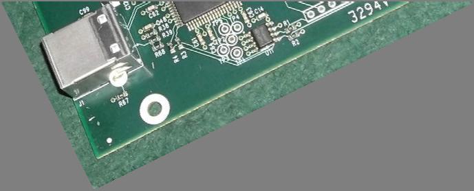
33 6.13 Board LEDs The main cluster of four LEDs is located in the lower right hand corner of the PCBA. Figure 25 identification of the four LEDs in lower-right hand corner of PCBA LED V Power supply is operational (upper right-hand corner near mounting hole) LED 5 quickly blinks and then turns ON? (1'b1) LED 1 blinks quickly when there is activity with I2C interface on the board LED 2 Counter using Symbol-Rate clock constantly blinks to show that FPGA is running. The rate of blinking will increase as the SR setting is increased. LED 3 PLL Lock 6.14 Optional Si570 Symbol Rate chip The PCBA has been designed with an etch foot print for an Si570 Symbol Rate PLL chip at position U12. If the Si570 is soldered onto the board, then the software will detect the chip will allow the Si570 to control the Symbol Rate setting with more precision. If U12 is not soldered in, then the FPGA will control the creation of the Symbol Rate flow. Anyone adding one of these Si570 chips to their board will have to use the 570CAC000121DG part from the Digi-Key distributor. The reason being that the software needs to know the factory-default start up frequency of the chip before it can calculate the calibrated reference oscillator frequency which it needs when programming the chip to other frequencies. The 570CAC000121DG is a CMOS device with a default start up frequency of 100 MHz and an I2C address of 55 hex. 33
34 7.0 Useful utilities 7.1 DVBinspector for TS files DVBinspector is a free Windows software program that can analyze various aspects of Transport Stream (TS) files. DVBinspector offers five different views of a transport stream; tree view (for logical analyzes), EIT view (fast overview of EIT information), bitrate view (to see bitrate alter over time), bar view (summary of average/minimum and maximum bitrates) and grid view (to see how different PIDs are distributed over time). Go to to download the utility software. Go to for the manual. 7.2 Playing Back TS files. The DATV-Express software can now create a Transport Stream (TS) file of your transmission (see the MAIN Tab in Section 6.12 for details on creating a TS file). If you want to play back and listen to the video on the TS files, there are listed below two utility programs that can play back TS file on your computer. 1. Use VLC player as the TS player on Ubuntu. VLC for Ubuntu can be downloaded free from 2. Use Windows Media Player as the TS player on Win7 7.3 CPU performance monitor There are several free CPU performance monitoring utilities that you can find on the internet for Ubuntu. Try SYSTEM MONITOR or my favorite SYSTEM LOAD INDICATOR that can be found at I usually adjust my monitor to be about 100 pixels wide. 7.4 Tutioune DVB-S analyzer Tutioune is a new software utility that has been specially developed to provide radio amateurs and DVB technicians with a tool that allows Digital ATV (DVB-S) to be measured precisely. With Tutioune you will no longer have the frustration of seeing only "level and "quality" information from standard satellite receivers including STBs; basic quality guidance that fails to satisfy technical users. Technical DVB-S users want to measure the received transmission characteristics exactly, so they can improve their systems and debug problems that may be encountered. Digital transmissions are not really "all or nothing", in between there are many things that can happen; it's important to be able to observe and define the various stages. 34
35 Tutioune is a software solution for making these measurements. This free Windows software utility was developed by F6DZP Jean Pierre Courjaud. The software can be downloaded from Tutioune can be used with a number of DVB-S PCI satellite receiver cards such as the TechnoTrend TT-S board ( 80 new and possibly less on ebay) or the best: TT S board. For these two families of card there are now two versions of software: Tutioune1600 for TT S you can find it here : Tutioune3200 for TT S you can find it here : 35
 Connector is SMA female. 0.59 3.18 2.875 2.47 0.77 0.")
36 8.0 DATV-Express Specifications Physical details: DC Power input: +9VDC to +15VDC 12V input) Female power jack 2.54 mm center Contact. Mates to Switchcraft #760 or equal plug 0.59 Status LEDs. See text for details RF output: 100MHz to +12dBm max. (1280MHz) Connector is SMA female USB2 type B Female Connector Data input from computer or host controller Data I/O conn: Optional data 5v logic levels. See text for details. Mounting holes: 4 x (3.16mm) for #4-40 or 3.5mm mtg. screws. It is recommended that the board be placed in an enclosure of some type, preferably of metal construction. The board mounting holes mate to a (5.6 x 4.3 x 1.8 ) Bud Industries or DigiKey part number #CU-387 plastic enclosure and may be used from an economy standpoint. The input and output connector holes must be added by the user. If a metal enclosure is used, it is helpful for heat distribution purposes to use metal mounting standoffs if possible. The modulator IC gets very warm during normal operation so using a metal standoff here will help sink heat away from it. Ventilation holes in the enclosure around the vicinity of the output connector is desired for elevated temperature environments. Environmental Details: Temperature 0 to +30 C (32-86 F) Humidity to 95% non-condensing Electrical Details: Required Computer components Host computer with at least (2) USB2 I/O ports available for DATV-Express USB interface cable USB type A connector at computer end, USB type B connector at DATV-Express end. Software support requirements for DVB-S, Pentium 4 running 2.4 GHz or better, 2GB available hard drive for DVB-T narrow bandwidths (2 & 3 MHz), dual-core CPU running 2.0 GHz should be adequate for DVB-T 2K mode to use all of the bandwidths, the CPU needs to be a quad-core i7 Operating system - 32 bit or 64 bit Ubuntu (Linux) Version 12.04LTS or newer. Downloadable at Hardware video capture card Hauppauge external USB models HVR-1950, HVR-1900, PVR-USB2 Hauppauge internal PCI-card models PVR-150, PVR-250, PVR-350 Input voltage requirements +9 to + 15VDC (400 ma@12vdc). Input is polarity protected but not fuse protected. External 1 amp slo-blo fuse is required by user for safe operation. Frequency Range 100MHz to 2450 MHz 36

 - 2.4%.")
37 Symbol Rate(MSymbols/sec) Select SR from 1.00 to 9.99 in 0.01steps. (Design is optimized for 2-6 MS/sec). There are 12 preset configurable combinations. Note: Symbol rates >8.00MS/sec show increased 12MHz sidebands on each side and 35 db down from center carrier because I/Q low pass anti-aliasing filters are optimized for 2-6 MS/sec. Below 1.5 MS/sec there could be some undesired aliases spurs (also +/- 12 MHz which is the Nyquist sampling frequency), if an interdigital bandpass filter is not used. Video displays will appear to be normal in either case. FEC Combinations: 1/2, 2/3, 3/4, 5/6, 7/8 for DVB-S and DVB-T protocol. Signal quality data EVM (Error Vector Magnitude) - 2.4%. (Measured with Agilent EXA N9010A Signal analyzer software VSA 89600B). ( 3% is acceptable for commercial broadcast). EVM is the percentage away from the ideal symbol landing spot in the signal constellation. This data is normally measured at the receiver and takes into account the combined effects of transmitter and receiver Carrier or Signal to Noise ratios (CNR or SNR). MER (Modulation Error Ratio) - 32dB. Minimum recommended downstream MER = 12-13dB for QPSK and 27dB for 64QAM including 3-4dB headroom for reliability. It s calculated as: 10LOG (average symbol power / average error power). Video Determined by capture card specs. Hauppauge model HVR1950 will accept 1V P-P 75 ohm NTSC or PAL video. Audio Determined by capture card selection. Compression: MPEG1 LED identification LED1 I 2 C activity - BLINK Blinks quickly during I 2 C communication. It s a very short blink and hard to see. LED2 Symbol Rate Counter Constant FLASH. Higher symbol rates = faster flashing. LED3 FX2 OK - ON ON if the USB controller is OK. LED4 +5V power - ON ON when +5.5VDC is present. LED5 PLL locked - ON ON for all normal operation. If OFF, there is a setup malfunction. 37
38 Connector details USB2 type B connector (J1) - Standard USB2 connections to/from host computer. RF output connector (J2) SMA female. DC power connector (J3) - Female DC connector, 2.54mm center pin. Mates to Switchcraft #760 or equal plug Data I/O connector (J4) vdc thru 50Ω 1/4w resistor Tx disable (Gnd to turn Xmit OFF) (Floats to +3.3V thru 100Ω for Xmit ON condition). Key (no pin) PLL locked (LED5)* (*This data is + true to 3.3V for function indicated. The I 2 C activity (LED1)* outputs are in parallel with LEDs thru a 100Ω resistor). Symbol Rate (LED2)* FX2 OK (LED3)* I 2 C buss SDA Reserved for future data communication/expansion and testing analysis. I 2 C buss SCL Reserved for future data communication/expansion and testing analysis. Ground Analog input 1 These inputs are reserved for forward and reverse power output signals Analog input 2 through a dual directional coupler. VSWR reporting and some linearization is possible with this data. Expansion connector (J6) Ground Key (no pin) FPGA I/O pin97 FPGA I/O pin 96 FPGA I/O pin 95 FPGA differential -output pin 72 FPGA differential +output pin 71 FPGA differential - input pin 70 FPGA differential + input pin 69 FPGA I/O pin 67 Transport Stream A transport stream feature is incorporated in the software to enable signal analysis. When the TS log to file button is checked, the computer will collect the active signal in a continuous datvexpress.ts data stream in the default Home directory. The data will continue to collect as long as the TS log to file button is checked at the rate of about MB/minute. The file can then be played back with Windows Media Player or equal software to view the video. The transport stream captured is the same one sent to the DATV-Express board in normal operation. (It is NOT the actual transmitted RF signal). Example: Your friend has a computer program with video analysis capability. You can the datvexpress.ts file to him so he can analyze your signal details as the video plays. 38
39 RF output Frequency range: 100MHz to 2450MHz. Resolution: 100 Hz Accuracy: ±2KHz Frequency stability: ± 100 PPM Output Impedance: 50 ohms Level: -34dBm to +13dBm in 1dB steps (100MHz) -35dBm to +12dBm in 1dB steps (1280MHz) -39dBm to +8dBm in 1dB steps (2450MHz) Spectral regrowth: -60dBc (RF output settings 00 to 35) -50dBc (RF output settings 36 to 47) Software controlled RF output: 00 to 47 in 1 db steps (00 is lowest level) The table above illustrates the RF signal level at 100, 1280 and 2450MHz frequencies verses the internal software controlled RF output settings. An RF output setting of 00 produces the minimum level of RF output from the board and a setting of 35 is the maximum RF level out with no detectable signal distortion (spectral regrowth). Above a setting of 35, some sideband regrowth becomes noticeable on a spectrum analyzer as the power level increases due to slight compression in the RF MMIC amplifier. The 100MHz carrier is given to establish a reference point. It is below what a QPSK signal is allowed on the Amateur radio frequencies.!caution! DO NOT ATTEMPT TO TRANSMIT A SIGNAL OUTSIDE THE ALLOWED HAM FREQUENCIES? The 100MHz and 1280MHz graph lines represent the true average power output for either the single carrier or QPSK signal. The 1280 SA graph line is included to show how the signal amplitude at top of haystack on a standard scalar Spectrum Analyzer compares to the true average power. The true power is actually close to 10dB greater than the SA reading! Note: A thermal milliwatt meter such as the Hewlett Packard model 432A, which has a bolometer probe does, in fact, indicate true power for both carrier only and QPSK signals. Use that data to predict post amplifier maximum input requirements. The graph at the right illustrates the harmonic content expected in the RF output signal. It MUST pass through a filter of some type in order to suppress unwanted harmonics. Since all unwanted frequencies are above the fundamental, a simple low pass filter may be all that is needed. The graph was created with a 100MHz signal to illustrate that the harmonic content extends many times beyond the fundamental. Only odd harmonics are produced. Even harmonics are below the SA measurable limit. If operation is planned for the 70cm band ( MHz), a third harmonic at ~1290MHz will be present about 26dB below the fundamental. DO NOT use an interdigital filter here as that type of filter passes the third harmonic with almost no added loss! Low pass filters are easy to construct and should be placed between the DATV- Express board and power amplifier, not after the PA. For low pass filter design examples go to The graph at the right illustrates how the RF output decreases as the output frequency increases. At software-controlled RF output setting = 30, a 100MHz 0dBm signal reduces to about - 5dBm at 1800MHz, everything else remaining the same. 39

40 QPSK Analysis: Since the spectral regrowth becomes noticeable when the attenuator output is greater than about 35, the graphs below show the RF output change as it passes thorough those points. From software-controlled RF output setting 00 to about 35, the regrowth is practically non-existent. The graph at the right was taken with attenuator = 30 on an Agilent EXA analyzer and external 10dB attenuator in place between the DATV- Express board and analyzer. It shows a top of the haystack signal of about -30dBm which equates to true power = -15.3dBm between the 6MHz green markers. (Signal level is lower here than in earlier references due to added cable length and external attenuator). The noise floor is about -95dBm. This represents the noise being about a 65dB below the main signal. The middle graph, taken with the software controlled output = 40 and external 20dB attenuator, shows slightly visible regrowth on each side of the main signal. It raises the noise floor up about 5dB resulting in distortion being down 60dB. This is still very good. The bottom graph, taken with RF output setting = 47 (highest RF output) and external attenuator, shows higher regrowth sidebands. Regrowth is now about 10dB above the -95dB noise floor but still well within acceptable transmission limits. Here the spectral regrowth is down ~ 50dB. The distortion and spurs on a QPSK DATV transmitter signal should be down at least 30 db or more from the main signal. Remember, any post signal amplification and (or) filters will tend to add distortion and decrease the overall signal quality. 40
DATV-Express Users Guide. (based on DATV-Express software build v1.09) Draft 16
 Draft 16") DATV-Express Users Guide (based on DATV-Express software build v1.09) Draft 16 1 Table of Contents 1.0 Prepare Disk Drive on PC... 4 1.1 Just reformat and devote the entire single drive for Ubuntu... 4
DATV-Express Users Guide (based on DATV-Express software build v1.09) Draft 16 1 Table of Contents 1.0 Prepare Disk Drive on PC... 4 1.1 Just reformat and devote the entire single drive for Ubuntu... 4
DATV-Express Users Guide For running on Windows OS. (based on Express_DVB-S/-S2/-T_Transmitter software v1.23-beta) Draft 010
 Draft 010") DATV-Express Users Guide For running on Windows OS (based on Express_DVB-S/-S2/-T_Transmitter software v1.23-beta) Draft 010 1 Table of Contents 1.0 Introduction... 6 2.0 Install Express_DVB S/ S2_Transmitter
DATV-Express Users Guide For running on Windows OS (based on Express_DVB-S/-S2/-T_Transmitter software v1.23-beta) Draft 010 1 Table of Contents 1.0 Introduction... 6 2.0 Install Express_DVB S/ S2_Transmitter
DATV-Express Users Guide For running on Windows OS. (based on Express_DVB _Transmitter software v1.25lp11) Draft 14
 Draft 14") DATV-Express Users Guide For running on Windows OS (based on Express_DVB _Transmitter software v1.25lp11) Draft 14 1 Table of Contents 1.0 Introduction... 5 2.0 Install Express_DVB_Transmitter software
DATV-Express Users Guide For running on Windows OS (based on Express_DVB _Transmitter software v1.25lp11) Draft 14 1 Table of Contents 1.0 Introduction... 5 2.0 Install Express_DVB_Transmitter software
AVE HOME FAGOR CVBS TO DVB-T ENCODER MODULATOR. Fagor Electr6nica
 AVE HOME CVBS TO DVB-T ENCODER MODULATOR FAGOR Fagor Electr6nica TABLE OF CONTENTS 1. SPECIFICATIONS... 12 1.1 Product Overview... 12 1.2 Appearance and Description... 12 1.3 Diagram... 13 1.4 Characteristics...
TechTalk123 - The MiniTiouner Receiver/Analyzer for Digital-ATV
 TechTalk123 - The MiniTiouner Receiver/Analyzer for Digital-ATV by Ken W6HHC Jean-Pierre F6DZP has been modifying Digital-ATV receivers for DVB-S protocol with software for years - in order to allow the
TV4U QUAD DVB-S2 to DVB-C TRANSMODULATOR
 INSTRUCTION MANUAL Features of the new DVB-C transmodulators line Through the use of the FPGA technology the transmodulators provides the highest performance at the lowest price. Four carriers are formed
QRF5000 MDU ENCODER. Data Sheet
 Radiant Communications Corporation 5001 Hadley Road South Plainfield NJ 07080 Tel (908) 757-7444 Fax (908) 757-8666 WWW.RCCFIBER.COM QRF5000 MDU ENCODER Data Sheet Version 1.1 1 Caution Verify proper grounding
2013 ARRL/TAPR DCC. DATV-Express
 2013 ARRL/TAPR DCC a Testing Report by Art Towslee towslee1@ee.net Ken Konechy W6HHC@ARRL.net WA8RMC W6HHC The Presentation Authors. Art WA8RMC Ken W6HHC 2 103 Status of Digital-ATV Today Video Quality
HD4112 Quad HDMI MPEG2 HD DVBT Encoder Modulator U S E R M A N U A L
 HD4112 Quad HDMI MPEG2 HD DVBT Encoder Modulator U S E R M A N U A L HD4112 Manual Rev 1 Contents 1. GENERAL 1.1 Description 1.2 Specifications 2. INSTALLATION 2.1 What s in the Box 2.2 Connection 2.2.1
AMD-53-C TWIN MODULATOR / MULTIPLEXER AMD-53-C DVB-C MODULATOR / MULTIPLEXER INSTRUCTION MANUAL
 AMD-53-C DVB-C MODULATOR / MULTIPLEXER INSTRUCTION MANUAL HEADEND SYSTEM H.264 TRANSCODING_DVB-S2/CABLE/_TROPHY HEADEND is the most convient and versatile for digital multichannel satellite&cable solution.
HD-1603 Single Input MPEG-4 DVB-T HD Encoder/Modulator User Guide and Install Manual
 ZyCastR digi-mod HD Range digi-mod HD-1603 www.digi-modbyzycast.com HD-1603 Single Input MPEG-4 DVB-T HD Encoder/Modulator User Guide and Install Manual Table of Contents www.digi-modbyzycast.com Safety
Update on DATV-Express exciter for Digital-ATV
 2015 ARRL/TAPR DCC by Update on DATV-Express exciter for Digital-ATV Ken Konechy W6HHC W6HHC@ARRL.net Abstract - The old technology of analog-atv suffers from susceptibility to snow and multi-path ghost
HV-122-DCA DVB-T 2-Way Diversity Receiver Box Quick Installation Guide
 HV-122-DCA DVB-T 2-Way Diversity Receiver Box Quick Installation Guide PACKAGE CONTENTS 4 FRONT PANEL VIEW 4 BACK PANEL VIEW 4 BOARD VIEW 5 IR REMOTE CONTROLLER-TYPE A 6 FILL BATTERY TO IR CONTROLLERS:
2011 ARRL TAPR Digital Comm Conference
 2011 ARRL TAPR Digital Comm Conference by Charles Brain G4GUO@ARRL.net Ken Konechy W6HHC@ARRL.net G4GUO W6HHC Status of Digital-ATV Today Video Quality of DATV far exceeds analog-atv Very few hams transmitting
INSTALLATION AND OPERATION INSTRUCTIONS EVOLUTION VIDEO DISTRIBUTION SYSTEM
 INSTALLATION AND OPERATION INSTRUCTIONS EVOLUTION VIDEO DISTRIBUTION SYSTEM ATTENTION: READ THE ENTIRE INSTRUCTION SHEET BEFORE STARTING THE INSTALLATION PROCESS. WARNING! Do not begin to install your
SPECIFICATION. DVB-T / Worldwide NIM Tuner
 1.Feature * DVB-T demodulator for COFDM with excellent multipath performance, meeting: * DVB-T Digital Television Standard ETS 300744 * Nordig-Unified v1.0.3 Receiver Specification 2.Applications * Digital
VIDEO GRABBER. DisplayPort. User Manual
 VIDEO GRABBER DisplayPort User Manual Version Date Description Author 1.0 2016.03.02 New document MM 1.1 2016.11.02 Revised to match 1.5 device firmware version MM 1.2 2019.11.28 Drawings changes MM 2
Table of Contents. 1. Safety Use. 2. General Description. 3. Connection Diagram. 4. Operations and Management. 4.1 Display Status. 4.
 DTM-HD01 Thank you for buying this encoder modulator. Please read this manual carefully to install, use and maintain the encoder modulator in the best conditions of performance. Keep this manual for future
DC-105 Quick Installation Guide
 DC-105 Quick Installation Guide PACKAGE CONTENTS 2 POWER ON 2 CONNECT TO A DVB-T RECEIVER 3 ADJUST THE FOCUS OF THE LENS 3 CONNECT TO A CVBS MONITOR 4 MIC-IN 4 USB UART DONGLE 5 MONITOR BOOT MESSAGES 7
TV4U DVB-S2 to DVB-S2 TRANSMODULATOR
 TV4U to TRANSMODULATOR TV4U to TRANSMODULATOR INSTRUTION MANUAL TV4U to TRANSMODULATOR The main application of to transmodulator Experience of MVDS terrestrial broadcasting shows that carrier must be restored
Portable TV Meter (LCD) USER S MANUAL
 USER S MANUAL") 1 Portable TV Meter User Manual (LCD) Portable TV Meter (LCD) USER S MANUAL www.kvarta.net 1 / 19 2 Portable TV Meter User Manual (LCD) Contents 1. INTRODUCTION... 3 1.1. About KVARTA... 3 1.2. About DVB...
1 Portable TV Meter User Manual (LCD) Portable TV Meter (LCD) USER S MANUAL www.kvarta.net 1 / 19 2 Portable TV Meter User Manual (LCD) Contents 1. INTRODUCTION... 3 1.1. About KVARTA... 3 1.2. About DVB...
Operation and Installation Guide
 Operation and Installation Guide HDS2800 Series Encoder Modulator High Definition (HD) Digital COFDM MPEG2 and H.264 Modulator with IP Multicast. 19 Rack Mount Revision 4.0 Firmware version Released File
SPECIFICATION. DVB-T/ DVB-C / Worldwide hybrid Switchable NIM Tuner
 1.Feature *. Integrated RF switch, NTSC VIF demodulator, COFDM demodulator *. All-in-one full NIM function with compact size, optimal solution for cost reduction and shortening product development lead-time.
Installation & Operational Manual
 Radiant Communications Corporation 5001 Hadley Road South Plainfield NJ 07080 Tel (908) 757-7444 Fax (908) 757-8666 WWW.RCCFIBER.COM QRF5000M MDU ENCODER Installation & Operational Manual Rev.A2 1. Introduction
User manual Transmodulators. Ref. 5103S/5103T/5103Q/5130
 User manual Transmodulators Ref. 5103S/5103T/5103Q/5130 Contents 1 Introduction 2 1.1 The ProQuad range................................ 2 1.2 Modular system solution.............................. 4 1.3
HD-1600 Single Input MPEG-4 DVB-T HD Encoder/Modulator User Guide and Install Manual
 digi-mod HD Range digi-mod HD-1600 www.resi-linx.com HD-1600 Single Input MPEG-4 DVB-T HD Encoder/Modulator User Guide and Install Manual Table of Contents Safety Precautions 2 Package Contents 2 Product
Single & Dual Input HD Digital DVB-T Modulators
 Radio Frequency Range Installation Diagram digi-mod HD-1000DM / HD-2000DM www.resi-linx.com Single & Dual Input HD Digital DVB-T Modulators ANT IN 1 2 3 4 AUX MOD RF IN TV OUTPUTS MOD RF IN (PWR/IR PASS)
VDT-100 User Manual 1
 VDT-100 User Manual 1 Copyright Notice The use manual, including all its contents, is copyrighted by Videa Technology Inc.. All rights are reserved. Videa Technology Inc. reserves the right to improve
USB Mini Spectrum Analyzer User s Guide TSA5G35
 USB Mini Spectrum Analyzer User s Guide TSA5G35 Triarchy Technologies, Corp. Page 1 of 21 USB Mini Spectrum Analyzer User s Guide Copyright Notice Copyright 2011 Triarchy Technologies, Corp. All rights
Notes on Using Hi-Des DVB-T Products with KH6HTV Video -- RF Linear Power Amplifiers Jim Andrews, KH6HTV
 AN-18 HiDesNotes.doc (kh6htv, rev. 10/30/14) p. 1 of 9 Application Note AN-18 copyright - Sept, 2014 Revised - Oct. 2014 Notes on Using Hi-Des DVB-T Products with KH6HTV Video -- RF Linear Power Amplifiers
HD168Bi Quad CVBS/HDMI HD DVBT Encoder Modulator U S E R M A N U A L
 HD168Bi Quad CVBS/HDMI HD DVBT Encoder Modulator U S E R M A N U A L Contents 1. GENERAL 1.1 Description 1.2 Specifications 2. INSTALLATION 2.1 What s in the Box 2.2 Connection 2.2.1 DEVICE Programming
Datasheet. Dual-Band airmax ac Radio with Dedicated Wi-Fi Management. Model: B-DB-AC. airmax ac Technology for 300+ Mbps Throughput at 5 GHz
 Dual-Band airmax ac Radio with Dedicated Wi-Fi Management Model: B-DB-AC airmax ac Technology for 300+ Mbps Throughput at 5 GHz Superior Processing by airmax Engine with Custom IC Plug and Play Integration
QRF5000 MDU ENCODER AND QAM MODULATOR
 Radiant Communications Corporation 5001 Hadley Road South Plainfield NJ 07080 Tel (908) 757-7444 Fax (908) 757-8666 WWW.RCCFIBER.COM QRF5000 MDU ENCODER AND QAM MODULATOR Installation & Operational Manual
SD4650 DVB-T HD MODULATOR. User Manual
 SD4650 DVB-T HD MODULATOR User Manual 0 TABLE OF CONTENT 1 GENERAL...2 1.1 Description...2 1.2 Specifications...3 2 INSTALLATION...4 2.1 What s in the Box...4 One power cable...4 2.2 Connection...4 2.2.1
USB Mini Spectrum Analyzer User Manual TSA Program for PC TSA4G1 TSA6G1 TSA8G1
 USB Mini Spectrum Analyzer User Manual TSA Program for PC TSA4G1 TSA6G1 TSA8G1 Triarchy Technologies Corp. Page 1 of 17 USB Mini Spectrum Analyzer User Manual Copyright Notice Copyright 2013 Triarchy Technologies,
VideoMate U3 Digital Terrestrial USB 2.0 TV Box Start Up Guide
 VideoMate U3 Digital Terrestrial USB 2.0 TV Box Start Up Guide Compro Technology, Inc. www.comprousa.com Copyright 2001-2005. Compro Technology, Inc. No part of this document may be copied or reproduced
Ultra-ViewRF 8HD Director Monitor. User Operation Manual
 Ultra-ViewRF 8HD 5.8GHz Wireless Director Monitor User Operation Manual 17.1.2013 v2_7 Video Equipment Rentals - VER 912 Ruberta Avenue Glendale, CA 91201 - U.S.A. Office 818-956-1444 Table of Contents
AT780PCI. Digital Video Interfacing Products. Multi-standard DVB-T2/T/C Receiver & Recorder & TS Player DVB-ASI & DVB-SPI outputs
 Digital Video Interfacing Products AT780PCI Multi-standard DVB-T2/T/C Receiver & Recorder & TS Player DVB-ASI & DVB-SPI outputs Standard Features - PCI 2.2, 32 bit, 33/66MHz 3.3V. - Bus Master DMA, Scatter
USB Mini Spectrum Analyzer User Manual PC program TSA For TSA5G35 TSA4G1 TSA6G1 TSA12G5
 USB Mini Spectrum Analyzer User Manual PC program TSA For TSA5G35 TSA4G1 TSA6G1 TSA12G5 Triarchy Technologies, Corp. Page 1 of 17 USB Mini Spectrum Analyzer User Manual Copyright Notice Copyright 2013
STM 26 HD. DVB-S2+T2/C Compact meter User Manual. Ref R13. CAHORS Digital CS Cahors Cedex 9 FRANCE
 STM 26 HD DVB-S2+T2/C Compact meter User Manual Ref 0145225R13 Preface USER MANUAL Please read this manual carefully before using your Digital Sat meter for the first time. This operating manual will help
Single cable multiswich programmer PC102W
 Single cable multiswich programmer PC102W 1. Product description The PC102W - single cable multiswich programmer (in the text - programmer) is useful instrument while configuring and troubleshooting SAT
Digital single HDMI Modulator to DVB-T/MPEG4. User s Guide
 Digital single HDMI Modulator to DVB-T/MPEG4 User s Guide Contents INTRODUCTION... 3 FEATURES... 3 Technical Specifications... 4 RF Specifications... 4 CONNECTIΟΝ & OPERATION... 5 PACKAGE INCLUDES... 5
user manual Colosseum 8500D
 user manual Colosseum 8500D No part of this manual may be copied, reproduced, transmitted, transcribed or translated into any language without permission. Unitron reserves the right to change the specifications
Wireless Studio. User s Guide Version 5.1x Before using this software, please read this manual thoroughly and retain it for future reference.
 4-743-161-12 (1) Wireless Studio User s Guide Version 5.1x Before using this software, please read this manual thoroughly and retain it for future reference. DWR-R01D/R02D/R02DN/R03D 2018 Sony Corporation
Digital Video Recorder
 Digital Video Recorder Quick Operation Guide UD.6L0202B0067A02 Thank you for purchasing our product. If there is any question or request, please do not hesitate to contact dealer. This manual is applicable
Operation and Installation Guide
 Operation and Installation Guide HDS2800 Series Encoder Modulator High Definition (HD) Digital COFDM MPEG2 and H.264 Modulator with IP Multicast. 19 Rack Mount Wall Mount Revision 0.1 Firmware version
DVB-T USB SET-TOP BOX
 DVB-T USB SET-TOP BOX User Manual Version: 1.0 (February 2005) TRANSYSTEM INC. No.1-2 Li-Hsin Rd.I Science-Based Industrial Park, Hsinchu, Taiwan Tel:+886-3-5780393 Fax:+886-3-5784111 e-mail: sales@transystem.com.tw
SingMai Electronics SM06. Advanced Composite Video Interface: HD-SDI to acvi converter module. User Manual. Revision 0.
 SM06 Advanced Composite Video Interface: HD-SDI to acvi converter module User Manual Revision 0.4 1 st May 2017 Page 1 of 26 Revision History Date Revisions Version 17-07-2016 First Draft. 0.1 28-08-2016
DIVERSITY DVB-T RECEIVER (DDR)
") User s Manual The most important thing we build is trust. DIVERSITY DVB-T RECEIVER (DDR) Cobham Surveillance GMS Products 1916 Palomar Oaks Way Ste 100 Carlsbad, CA 92008 100-M0062X2 T: 760-496-0055 05/15/09
User s Manual The most important thing we build is trust. DIVERSITY DVB-T RECEIVER (DDR) Cobham Surveillance GMS Products 1916 Palomar Oaks Way Ste 100 Carlsbad, CA 92008 100-M0062X2 T: 760-496-0055 05/15/09
CI-218 / CI-303 / CI430
 CI-218 / CI-303 / CI430 Network Camera User Manual English AREC Inc. All Rights Reserved 2017. l www.arec.com All information contained in this document is Proprietary Table of Contents 1. Overview 1.1
AT2780USB. Digital Video Interfacing Products. DVB-T/H/C & ATSC Modulator IF and RF ( VHF & UHF ) Output DVB-ASI & DVB-SPI Inputs
 Output DVB-ASI & DVB-SPI Inputs") Digital Video Interfacing Products AT2780USB DVB-T/H/C & ATSC Modulator IF and RF ( VHF & UHF ) Output DVB-ASI & DVB-SPI Inputs Standard Features DVB-T/H/C Modulator with VHF & UHF Up converter. - High
Digital Video Interfacing Products AT2780USB DVB-T/H/C & ATSC Modulator IF and RF ( VHF & UHF ) Output DVB-ASI & DVB-SPI Inputs Standard Features DVB-T/H/C Modulator with VHF & UHF Up converter. - High
1080P DVB-T MODULATOR WITH HDMI LOOP THROUGH + RF output + RF input
 1080P DVB-T MODULATOR WITH HDMI LOOP THROUGH + RF output + RF input USER GUIDE 0 TABLE OF CONTENT 1 GENERAL...2 1.1 Description...2 1.2 Specifications...3 2 INSTALLATION...5 2.1 Power Supply...5 2.1.1
Introduction This application note describes the XTREME-1000E 8VSB Digital Exciter and its applications.
 Application Note DTV Exciter Model Number: Xtreme-1000E Version: 4.0 Date: Sept 27, 2007 Introduction This application note describes the XTREME-1000E Digital Exciter and its applications. Product Description
SAT IF distribution system
 7. Technical specifications Type cs43 RF input frequency range pr. 50-350 MHz inputs number 4 level pr. 55...88 dbµv 60...93 dbµv symbol rate 3 45 Ms/s return loss/impedance > 0 db/75 Ω LNB powering/control
The Kaffeine Handbook. Jürgen Kofler Christophe Thommeret Mauro Carvalho Chehab
 Jürgen Kofler Christophe Thommeret Mauro Carvalho Chehab 2 Contents 1 Kaffeine Player 5 1.1 The Start Window...................................... 5 1.2 Play a File..........................................
SNG-2150C User s Guide
 SNG-2150C User s Guide Avcom of Virginia SNG-2150C User s Guide 7730 Whitepine Road Revision 001 Richmond, VA 23237 USA GENERAL SAFETY If one or more components of your earth station are connected to 120
16 channels transmodulator S2C16
 16 channels transmodulator S2C16 Vers. 1.01 USER S MANUAL S2C16 - SAT to QAM transmodulator 1. Product description S2C16 is a 16 channel transmodulator with DVB-S/S2 input and DVB-C output. It has 4 main
CompactMax-2 DVB-S/S2 TO DVB-T2 TRANSMODULATOR - 0 MI2100 -
 CompactMax-2 DVB-S/S2 TO DVB-T2 TRANSMODULATOR - 0 MI2100 - SAFETY NOTES Read the user s manual before using the equipment, mainly "SAFETY RULES" paragraph. The symbol on the equipment means "SEE USER
Scan Converter Installation Guide
 Scan Converter Installation Guide Software on supplied disks Please note: The software included with your scan converter is OPTIONAL. It is not needed to make the scan converter work properly. This software
INT-DS2 DVB-S/S2 SATELLITE MODULATOR DVB MODULATOR
 INT-DS2 DVB-S/S2 SATELLITE MODULATOR Key Features In compliance with DVB-S/S2/DSNG and in partial compliance with DVB-S2x standards. Supporting up to 200Mbps at ASI and 80Mbps at TSoIP input. Capable to
Configuring and Troubleshooting Set-Top Boxes
 Diagnose RF Tuner Issues, page 1 Protect End-User Privacy, page 4 Apply Services to Device, page 5 View Video Recordings, page 6 View VOD Programs, page 6 View PDL Programs, page 7 View Hard Disk Information,
Booya16 SDR Datasheet
 Booya16 SDR Radio Receiver Description The Booya16 SDR radio receiver samples RF signals at 16MHz with 14 bits and streams the sampled signal into PC memory continuously in real time. The Booya software
T3316 IP QAM Modulator User Manual
 T3316 IP QAM Modulator User Manual SW Version: 1.02 HW version: 0.70.0.0 Web NMS version: 1.02 Intended Audience About This Manual This user manual has been written to help people who have to use, to integrate
Manual of Operation for WaveNode Model WN-2m. Revision 1.0
 Manual of Operation for WaveNode Model WN-2m. Revision 1.0 TABLE OF CONTENTS 1. Description of Operation 2. Features 3. Installation and Checkout 4. Graphical Menus 5. Information for Software Expansion
NanoGiant Oscilloscope/Function-Generator Program. Getting Started
 Getting Started Page 1 of 17 NanoGiant Oscilloscope/Function-Generator Program Getting Started This NanoGiant Oscilloscope program gives you a small impression of the capabilities of the NanoGiant multi-purpose
A LOW COST TRANSPORT STREAM (TS) GENERATOR USED IN DIGITAL VIDEO BROADCASTING EQUIPMENT MEASUREMENTS
 GENERATOR USED IN DIGITAL VIDEO BROADCASTING EQUIPMENT MEASUREMENTS") A LOW COST TRANSPORT STREAM (TS) GENERATOR USED IN DIGITAL VIDEO BROADCASTING EQUIPMENT MEASUREMENTS Radu Arsinte Technical University Cluj-Napoca, Faculty of Electronics and Telecommunication, Communication
A LOW COST TRANSPORT STREAM (TS) GENERATOR USED IN DIGITAL VIDEO BROADCASTING EQUIPMENT MEASUREMENTS Radu Arsinte Technical University Cluj-Napoca, Faculty of Electronics and Telecommunication, Communication
Professional Radio TV, SAT & CATV Probe with IP Encap/Decap, ASI output, T.S. Analysis, HDSD SDI Output, Remote control with NMS & SNMP.
 EX AMINER Professional Radio TV, SAT & CATV Probe with IP Encap/Decap, ASI output, T.S. Analysis, HDSD SDI Output, Remote control with NMS & SNMP....Made to Measure... PROFESSIONAL SAT - TV - CATV PROBE
Receiving DATV on four bands with Digital Satellite TV equipment
 Receiving DATV on four bands with Digital Satellite TV equipment By Grant VE3XTV Background: ATV started out on the 70 cm BAND using AM modulation and all contacts were made via simplex. The receivers
CompactMax-4 DVB-S/S2 TO ISDB-T TRANSMODULATOR - 0 MI2101 -
 CompactMax-4 DVB-S/S2 TO ISDB-T TRANSMODULATOR - 0 MI2101 - SAFETY NOTES Read the user s manual before using the equipment, mainly "SAFETY RULES" paragraph. The symbol on the equipment means "SEE USER
FireTV User's Guide 1
 FireTV User's Guide 1 Table of contents 1. Introduction... 3 Features:... 3 Input:... 3 Output:... 3 Technology Summary... 4 DVB Overview... 4 Digital Satellite Equipment Control (DiSEqC) Overview... 5
User Manual. HDMI Modulator Ref & SW Release
 User Manual HDMI Modulator Ref. 8201 & 8202 SW 1.1.1.Release No part of this manual may be copied, reproduced, transmitted, transcribed or translated into any language without permission. Unitron reserves
User guide. IP output module - Art. No A
 User guide IP output module - Art. No. 492072 891080A GB Contents Contents Disposal... 3 Box content... 3 IP output module... 3 Labels... 4 Installation of IP modules... 5 Installation of extender boards...
Z-IP Stream 004/008. User Guide and Installation Manual. Four or Eight Input QAM Encoder / Modulator
 Z-IP Stream 004/008 User Guide and Installation Manual Four or Eight Input QAM Encoder / Modulator MPEG-2 / H.264 HD ENCODER with QAM /IP/ & ASI Outputs Contents Safety Precautions... 3 Package Contents...
User guide MAW-300. Ref HD Encoder & Modulator HDMI to DVB-T
 User guide MAW-300 Ref. 3030 HD Encoder & Modulator HDMI to DVB-T 1 Index Safety Instructions... 3 General Description... 4 Working Principie... 4 Technical Specifications... 5 Installations... 6 Typical
DIGITAL MODULATOR DMSD01 AV TO DVB-T ENCODER/MODULATOR USER MANUAL
 DIGITAL MODULATOR DMSD01 AV TO DVB-T ENCODER/MODULATOR USER MANUAL CONTENTS 1 Safety considerations page 3 2 Description of the different elements page 4 3 Installation and menu structure page 5 3.1 Installation
AT660PCI. Digital Video Interfacing Products. DVB-S2/S (QPSK) Satellite Receiver & Recorder & TS Player DVB-ASI & DVB-SPI outputs
 Satellite Receiver & Recorder & TS Player DVB-ASI & DVB-SPI outputs") Digital Video Interfacing Products AT660PCI DVB-S2/S (QPSK) Satellite Receiver & Recorder & TS Player DVB-ASI & DVB-SPI outputs Standard Features - PCI 2.2, 32 bit, 33/66MHz 3.3V. - Bus Master DMA, Scatter
Digital Video Interfacing Products AT660PCI DVB-S2/S (QPSK) Satellite Receiver & Recorder & TS Player DVB-ASI & DVB-SPI outputs Standard Features - PCI 2.2, 32 bit, 33/66MHz 3.3V. - Bus Master DMA, Scatter
Lab experience 1: Introduction to LabView
 Lab experience 1: Introduction to LabView LabView is software for the real-time acquisition, processing and visualization of measured data. A LabView program is called a Virtual Instrument (VI) because
HD RANGER+ Evolution? NO. Revolution!
 Evolution? NO. Revolution! The SIXTH GENERATION field meter FROM PROMAX lite ACTUAL SIZE - 7 SCREEN (APPROX. 155 x 93 mm) Revolutionising the market. Again The largest and brightest display HD RANGER+
SingMai Electronics SM06. Advanced Composite Video Interface: DVI/HD-SDI to acvi converter module. User Manual. Revision th December 2016
 SM06 Advanced Composite Video Interface: DVI/HD-SDI to acvi converter module User Manual Revision 0.3 30 th December 2016 Page 1 of 23 Revision History Date Revisions Version 17-07-2016 First Draft. 0.1
User s Manual HDMI Modulator ATSC 8VSB/QAM 65/256. Model No : HDM100
 User s Manual HDMI Modulator ATSC 8VSB/QAM 65/256 Model No : HDM100 Contents 1. Safety Instructions & Precautions. 1 2. Operation Guide.. 2 2-1. Connection Diagram. 2 2-2. Front Panel.... 3 2-3. Rear Panel.....
User s Guide W-E
 Presto! PVR ISDB User s Guide 518100-02-01-W-E-112307-02 Copyright 2007, NewSoft Technology Corp. All Rights Reserved. No portion of this document may be copied or reproduced in any manner without prior
AT278USB, imod. Digital Video Interfacing Products. DVB-T/H/C & ATSC Modulator IF and RF ( VHF & UHF ) Output DVB-ASI Input
 Output DVB-ASI Input") Digital Video Interfacing Products AT278USB, imod DVB-T/H/C & ATSC Modulator IF and RF ( VHF & UHF ) Output DVB-ASI Input Standard Features DVB-T/H/C Modulator with VHF & UHF Up converter. - High Speed
Digital Video Interfacing Products AT278USB, imod DVB-T/H/C & ATSC Modulator IF and RF ( VHF & UHF ) Output DVB-ASI Input Standard Features DVB-T/H/C Modulator with VHF & UHF Up converter. - High Speed
B. The specified product shall be manufactured by a firm whose quality system is in compliance with the I.S./ISO 9001/EN 29001, QUALITY SYSTEM.
 VideoJet 8000 8-Channel, MPEG-2 Encoder ARCHITECTURAL AND ENGINEERING SPECIFICATION Section 282313 Closed Circuit Video Surveillance Systems PART 2 PRODUCTS 2.01 MANUFACTURER A. Bosch Security Systems
D R M A X - 2 DDS FREQUENCY SYNTHESIZED DRM MW TRANSMITTER. User s Guide (Please read carefully before using for the first time!)
") D R M A X - 2 DDS FREQUENCY SYNTHESIZED DRM MW TRANSMITTER User s Guide (Please read carefully before using for the first time!) Copyright 2018 by ASPiSYS Ltd. DRMAX2 is a low-power DRM MW transmitter.
D R M A X - 2 DDS FREQUENCY SYNTHESIZED DRM MW TRANSMITTER User s Guide (Please read carefully before using for the first time!) Copyright 2018 by ASPiSYS Ltd. DRMAX2 is a low-power DRM MW transmitter.
Digital Compact Headends
 Johansson introduces the range of Digital Compact Headends, known as Colosseum. Already shortly after their introduction in Germany, these compact TV distribution stations were recommended by several magazines
4T2-Portable test set DVB terrestrial analyser system
 1a test set DVB terrestrial analyser system COFDM analyser with MER performance >42 db in real-time 4k capable diversity receiver Spectrum, impulse response, group delay, and CCDF Automated multi-channel
Laboratory stand description. Investigation of DVB-T/C/IPTV technologies
 1 Laboratory stand description Investigation of DVB-T/C/IPTV technologies Table of Contents 1. Hardware prerequisites... 3 1.1 Hardware parts... 3 1.2 Cables required for system interconnection... 5 1.3
Simple Media Platform Quick Installation Guide V1.0-N. Simple Media Platform. Quick Installation Guide
 Simple Media Platform Quick Installation Guide 1. Installation Instruction 1.1 Mounting unit to a 19 rack When selecting the installation site, try to comply with the following: Protective Ground - The
EVD-L04/100A1-960, EVD-L08/200A1-960 and. EVD-L16/400A1-960 DVRs. Quick Operation Guide
 EVD-L04/100A1-960, EVD-L08/200A1-960 and EVD-L16/400A1-960 DVRs Quick Operation Guide Thank you for purchasing our product. If there is any question or request, please do not hesitate to contact dealer.
MyM-3S Micro Master. Installation Guide. English. design for TV
 MyM-3S Micro Master Installation Guide design for TV 1 CONTENT 1. Introduction 2. Unpacking the unit 3. Connections and indications 4. IP settings 5. Menus and settings 5.1 Overview menu 5.2 Input settings
DVR-431 USB Wireless Receiver User Manual
 DVR-431 USB Wireless Receiver User Manual Thank you for using our wireless USB receiver, please read the following content carefully before using, it will help you make better use of this product. Introduction
Xpresionn Digital Terrestrial Receiver. User Guide
 Xpresionn 2150 Digital Terrestrial Receiver User Guide GENERAL INFORMATION...3 A) SAFETY PRECAUTIONS...3 B) MAIN FEATURES...4 C) CONTENTS OF THE PACKAGING...4 D) REMOTE CONTROL...5 INSTALLATION...6 A)
RF Semiconductor Test AXRF RF Port Upgrade Kits
 RF Semiconductor Test AXRF RF Port Upgrade Kits 2017 Datasheet The most important thing we build is trust Overview AXRF RF Port Upgrade Kits are designed to improve and extend the capability of an existing
SYMBOLS USED ON THE RECEIVER... 3 SAFETY INSTRUCTIONS... 4 I.GENERAL INFORMATION...
 Table of Contents SYMBOLS USED ON THE RECEIVER... 3 SAFETY INSTRUCTIONS... 4 I.GENERAL INFORMATION... 5 1. Preface... 5 2. Main Features... 5 3. General Operation of the Receiver... 6 4. Front Panel...
Teletext Inserter Firmware. User s Manual. Contents
 Teletext Inserter Firmware User s Manual Contents 0 Definition 3 1 Frontpanel 3 1.1 Status Screen.............. 3 1.2 Configuration Menu........... 4 2 Controlling the Teletext Inserter via RS232 4 2.1
Installation / Set-up of Autoread Camera System to DS1000/DS1200 Inserters
 Installation / Set-up of Autoread Camera System to DS1000/DS1200 Inserters Written By: Colin Langridge Issue: Draft Date: 03 rd July 2008 1 Date: 29 th July 2008 2 Date: 20 th August 2008 3 Date: 02 nd
IRIG-B PTP Clock Converter Output Module Hardware Installation Manual
 IRIG-B PTP Clock Converter Output Module Hardware Installation Manual Kyland Technology Co., LTD. Publication Date: May 2012 Version: V1.2 Customer Service Hotline: (+8610) 88796676 FAX: (+8610) 88796678
DQT1000 MODEL DIGITAL TO QAM TRANSCODER WITH DIGITAL PROCESSING AND MULTIPLEXING
 MODEL DQT1000 DIGITAL TO QAM TRANSCODER WITH DIGITAL PROCESSING AND MULTIPLEXING The R. L. Drake model DQT1000 is a professional quality, digital headend transcoder product that tunes and demodulates MPEG2
DTV/MPEG2 Test & Measurement DTV Signal Generator DSG500
 DTV/MPEG2 Test & Measurement DTV Signal Generator DSG500 Copyright 2007 DTVinteractive Co., Ltd. All rights reserved. DSG500 DTV Signal Generator General DSG500 is the all-in-one DTV signal generator supporting
Long Range Wireless HDMI/SDI HD Video Transmission Suite LINK-MI LM-SWHD01. User manual
 Long Range Wireless HDMI/SDI HD Video Transmission Suite LINK-MI LM-SWHD01 User manual Preface... 1 1. Cautions... 2 2. About... 3 3. Installation... 4 4. Operation instruction... 5 5. Maintenance... 6