SAFETY OF FITNESS EQUIPMENT CABLES By Ralph L. Barnett 1
|
|
|
- Howard Hicks
- 6 years ago
- Views:
Transcription
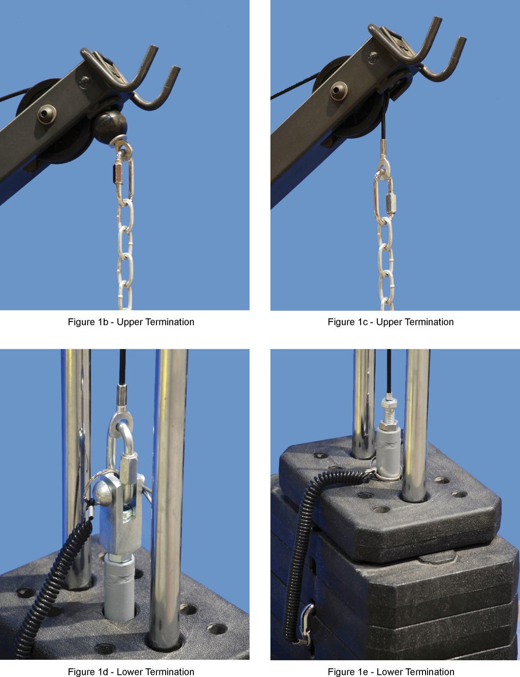
1 SAFETY OF FITNESS EQUIPMENT CABLES By Ralph L. Barnett 1 Abstract There is a family of exercise machines that provides a manual workout task requiring the user to push or pull against a resistance provided by a stack of weight plates. The weight system is usually linked with a single cable to a gripping or user interface device to produce a constant resistance. A fracture of the tensioned cable along its length or at its end connectors causes a sudden acceleration of the grip or other interface device driven by the operator s push or pull. The sudden loss of resistance often results in an exerciser pulling a heavy bar into his or her face. Because falling weights, accelerating grips and rapidly unloading muscles are all hazardous, manufacturers of exercise machines want to maintain the structural integrity of the cables. To accomplish this, manufacturers usually recommend scheduled servicing of their cables. This Preventive Maintenance (PM) strategy is frustrated by nylon sheathing that hides the cable failures. Further, the swedged or silver soldered connectors often fail covertly by internal fatigue fractures. A more effective PM strategy has been adopted by many manufacturers called Scheduled Replacement ; they advocate annual cable replacement. Here the nemeses are sloth and greed, best expressed by the philosophy, if it ain t broke, don t fix it. As a first consideration of fault tolerant design, a redundant duplication of the cable system was added to a fitness machine; this is called active redundancy. This paper demonstrates the inadequacy of active redundancy for eliminating the catastrophic failure mode. Instead, the adoption of a dormant/standby redundancy is shown to provide the requisite safety. The proposed system not only eliminates the fail-to-danger mode, it provides the most economical use of the cable in the sense that it never discards a cable until its life is exhausted. I. Introduction Hanging weights are generally used to provide a constant resistance over the full pulling range on fitness equipment. These weights are usually suspended by a cable mechanism that transfers a selected gravity load to various portions of a human body through handles or foot pedals. This is illustrated by the stripped down fitness machine shown in Figure 1. Manufacturers typically use an aircraft cable (seven strands with 19 wires per strand) that is 3/16 in diameter and covered in a nylon sheath. This highly redundant wire rope is composed of 133 wires; it uses end connectors that are usually swedged and/or silver soldered. 1 Professor, Mechanical & Aerospace Engineering, Illinois Institute of Technology, Chicago, IL; Chairman, Triodyne Inc., Northbrook, IL
2 2
3 3
4 Fitness equipment manufacturers generally advocate preventive maintenance (PM) techniques for maintaining the structural integrity of the cables. Preventive maintenance is defined as actions performed in an attempt to retain an item in a specified condition by providing systematic inspection, detection and prevention of incipient failure by repairing or replacing it. This concept must be contrasted with corrective maintenance which restores an item to a specified condition after it has failed. The two principal PM techniques are scheduled servicing and scheduled replacement [Ref. 1, 2]. Scheduled Servicing: Scheduled servicing is comprised of scheduled maintenance strategies which reveal incipient failures of items for the purpose of preventing system failures. Various servicing protocols are involved: a) Inspection detection of self-revealing deteriorating conditions of items composing the system. b) Non-destructive testing a body of testing techniques and methods which will not compromise the item tested. c) Cleaning d) Lubrication e) Calibration f) Adjustment g) Repair (if required) In 2001, various representatives of the fitness industry published the following recommendations for maintaining cables: Body Master: All belts and/or cables on all machines must be carefully inspected on a daily basis for any signs of wear, fraying, de-lamination and/or stretching. Replace worn or damaged belts (cables) immediately. Pyramid: Inspect cable wear (weekly). 4
5 Bally Total Fitness: Inspect cables daily. Replace at first signs of wear. These three recommendations precisely reflect the PM strategy called Scheduled Servicing. It is very effective for identifying damaged sheathing; on the other hand, it is an impoverished procedure for identifying the onset of fatigue failure. Fatigue of wire rope manifests itself by successive failures of the constituent wires which form wire fractures often called fish hooks on the cable surface. Wire rope is a highly redundant tension member that communicates its compromised structural integrity before it fully separates [Ref. 3]. Unfortunately, the nylon sheathing that covers most fitness machine cables hides most wire failures. Furthermore, wire rope failure may occur inside of the end fasteners where no visual feedback is available. The author has investigated such internal fatigue failure on cable showing no other signs of distress. Scheduled Replacement: Scheduled replacement involves the replacement of parts at pre-determined times before failure. When the onset of failure of an item cannot be determined, scheduled replacement is the only PM strategy available. Reliability analysis techniques are required to develop replacement schedules that will minimize the number of items which fail. On the other hand, inefficient replacement or maintenance schedules may be adopted through trial and error or anecdotal observations. The author s survey of ten fitness organizations in 2001 uncovered the following additional guidelines for cable maintenance: Icarian: Replace cables annually. Cybex: Replace all cables at least annually. Bodymaster: All belts (cables) must be replaced every two years. Bally Total Fitness: All cables shall be changed annually or sooner as needed. Observe that the above cited guidelines require cable replacement regardless of the condition of the wire rope. This is precisely the PM policy of Scheduled Replacement. Every one of the ten manufacturers in our small study required immediate cable replacement after wear was detected; but most did not specify replacement when no damage was detected. 5
6 Keeping track of the age of fitness machine cables requires discipline. Throwing away one-yearold cables with no apparent damage goes against the grain of frugality and resource conservation. Changing out cables that are inspected daily is work. Many sized new cables must be ordered and inventoried, and operations must be interrupted while new cables are installed. It is easier to ignore scheduled replacement and replace only broken cables or ones with compromised appearance. The first remediation technique, Scheduled Servicing, is part of the Doctrine of Manifest Danger [Ref. 3] and requires self-revealing deteriorating conditions. The second technique, Scheduled Replacement, requires a cable replacement interval that precludes cable failure. Both systems are active; diligent inspection schedules or regular replacement schedules are critical. II. Fail-Safe Cable Design Because PM has not proven to be a satisfactory solution to the problem of cable fracture, it is reasonable to embrace the techniques of fail-safe design. The objective of a fail-safe design is to create a system that sets up a safe condition when a fault occurs. Specifically, failure of a cable should not result in a potential for injury or disaster. Simple redundancy can be achieved by substituting two identical cable systems for the original cable system. This design is called Active Parallel Redundancy [Ref. 4]. A. Active redundancy Active redundancy is characterized as redundancy wherein all redundant items are operating simultaneously rather than being switched on when needed. The fatigue machine illustrated in Figure 1 was modified by duplicating the original cable system; the resulting redundant machine is shown in Figure 2. Because of symmetry, each of the cables shown in Figure 2b shares the load equally. The resulting lower stress in each cable will extend its life. The conventional argument suggests that when one of the cables fails, the survivor will continue to carry the weights and the failed cable will give notice of the component failure. Upon reflection, this redundant design uses two already redundant nominally identical wire ropes which are woven using a large number of individual wires. The failure of a single wire rope proceeds by a succession of fatigue failures of the wire strands. Eventually, the surviving wires become sufficiently overloaded that the applied tensile stress exceeds the ultimate tensile resistance of the wire strands. When two cables are loaded identically, one would expect the percentage of wire fractures in either cable to be roughly equivalent. Consequently, when one cable breaks, it subjects the other cable, which is on the brink of failing, to twice the applied 6
7 load, usually causing it to fail as well. Theoretically, if each cable contained an infinite number of wires, both cables would break simultaneously. Because the number of wires is finite, one cable will always fail first. 7

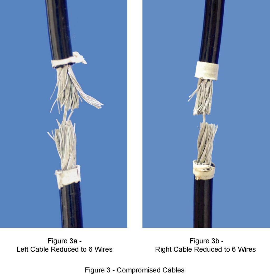
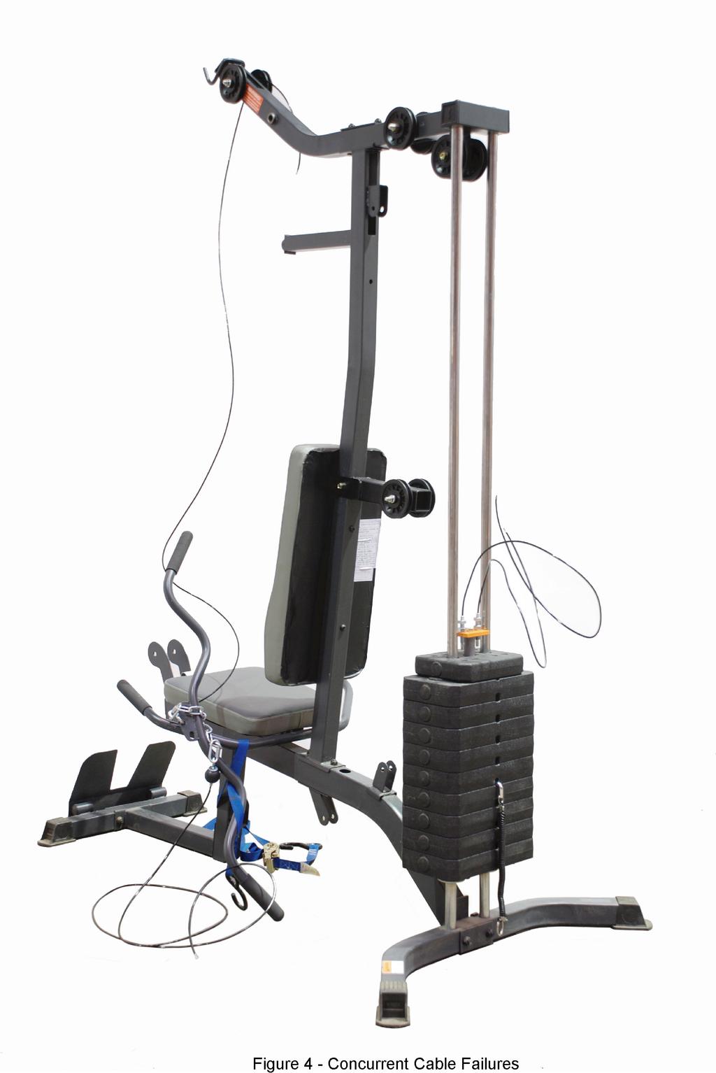
8 As a demonstration of active redundancy one of the two new cables shown in Figure 2b was deliberately cut. The surviving cable continued to equilibrate the load; this is conventional behavior. This test shows how active redundancy preserves the structural integrity of the cable system in the face of a random traumatic threat to one of the cables. PM will not provide this protection. As a second demonstration, one section of each cable was reduced from 133 wires to 6 wires as shown in Figure 3a and 3b. Again, one of the cables was deliberately cut and the survivor immediately fractured because the six surviving wires could not support the weight stack as shown in Figure 4. 8
9 9
10 10
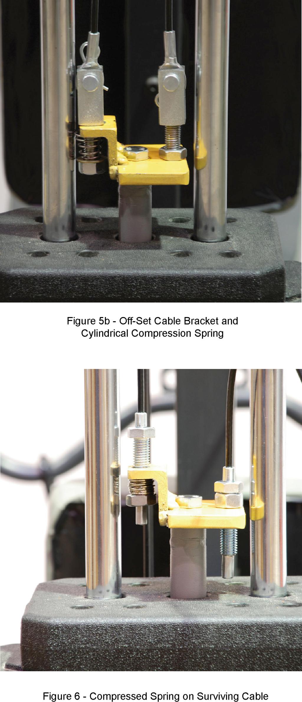
11 In summary, active redundancy improves the system reliability. The simple act of redundancy will harden the system against traumatic insult to any one of the cables. However, the safety threat of fatigue failure is only prolonged because of the likelihood of dual cable system failure. B. Dormant Standby Redundancy Because active parallel redundancy does not eliminate the possibility of cable system failure, a second type of failsafe design is proposed, Dormant Standby Redundancy [Ref. 5]. Dormant standby redundancy is an alternative means of performing a function which is inoperative until needed; switched on upon failure of the primary means of performing the function. An example is the new spare tire in an automobile. The spare tire is not in use until it is substituted for a damaged tire by the automobile s operator. Another example is an ordinary scaffold system which has a new cable life line for each person using the scaffold. If the scaffold collapses, each of the workers is tied off to his own brand new lifeline which is entirely independent of the cables that are holding up the scaffold. The lifelines cannot be used again after a scaffold collapses. The American National Standard, ANSI A , American National Standard for Construction and Demolition Operations Requirements for Safety Belts, Harnesses, Lanyards and Lifelines for Construction and Demolition Use states the following [Ref. 6]: All fall protection systems subjected to impacts caused by a freefall or by testing shall be removed from service and should not be used again. As a consequence, scaffold workers are always protected by a new lifeline. The proposed weight machine cable system is shown in Figure 5a. The dual cables are affixed to the weight stack by the offset plate and compression spring depicted in Figure 5b. Any force applied to the left cable merely shortens the compression spring which limits the left cable loading to about 15 lb. Almost the entire weight stack is lifted by the right cable. If this right cable or its terminations are fractured because of trauma or fatigue, the weight is automatically switched to the like new left cable which bottoms out the compression spring as shown in Figure 6 for a different style end connector. Observe that the right cable assumes a serpentine geometry that notifies the operator of a component failure. 11
12 12
13 13
14 When the right cable fractures, its load is transferred to the left cable through a spring. The weight stack falls less than an inch. The broken cable manifests its fracture while an almost new cable continues to support the exercise activity. After the failure, the standby cable is moved to the right position to become the primary load bearing cable. A new cable is substituted for the left cable and becomes the dormant standby member. Observe that the full life of the right cable has been realized, whereas the scheduled replacement PM protocol throws away cables which may have substantial remaining life. The dormant standby redundant cable system provides a flexible strategy that is easily applied to fit machines with different configurations as shown in Figures 7, 8 and 9. Figure 10 replaces the compression spring with a gravity or spring loaded idler roller which takes up the slack in the dormant standby cable. The cylindrical compression spring can be replaced by a conical spring that provides a shorter compressed height. All of the proposed systems require an offset or phase shift between the parallel cable systems. 14
15 15
16 16
![III. Conclusions and Observations A. The earliest maintenance concept associated with fitness machines was if it aint broke, don t fix it [Ref. 7]. B.](/docs-images/75/71553147/images/17-0.jpg "This was followed by a notion that has modern day outcroppings, if a cable defect manifests itself, replace the cable immediately. No maintenance intervals are recommended. C.")
17 III. Conclusions and Observations A. The earliest maintenance concept associated with fitness machines was if it aint broke, don t fix it [Ref. 7]. B. This was followed by a notion that has modern day outcroppings, if a cable defect manifests itself, replace the cable immediately. No maintenance intervals are recommended. C. Fitness machine manufacturers and health clubs began to embrace the preventive maintenance concept, scheduled servicing. They called for cable inspections to take place in various combinations of daily, weekly, monthly and yearly. 17
18 D. Scheduled servicing is capable of detecting overt or self-revealing faults. It is maintenance intensive and it is subject to human errors associated with subjective observations. E. Scheduled servicing will not detect covert faults. Normal cable diagnosis is compromised by the nylon sheathing covering the cables. Connectors can fail by internal fatigue mechanisms that are completely hidden from view. F. Today, fitness machine manufacturers and health clubs have added a second PM concept to their cable maintenance program, scheduled replacement. Typically there is an admonition to replace the cables annually regardless of their appearance or condition. G. The PM strategies will not protect against failure of cable systems caused by random traumatic assault. H. The new PM philosophy which embraces both scheduled servicing and scheduled replacement is not adequate for dealing with the broken cable potential. The combined system is maintenance intensive and requires strict attention to record keeping so that the cable replacements can be made with fidelity. Furthermore, as mentioned above, there are excursions that are traumatic in nature which cannot be protected by the PM concepts. It is reasonably foreseeable that human error will compromise the new PM strategy. I. The simplest fault-tolerant concept, active parallel redundancy, simply requires the addition of a duplicate of the original cable system. Fail-safe design is very effective for preventing catastrophic failure of the cable system when the cable elements contain random defects or suffer traumatic assaults. On the other hand, when fatigue failure compromises both cables simultaneously the failure of one cable transfers its load to the surviving cable which usually cannot handle the double loading. The cable fracture hazard is not averted. J. The application of a fail-safe concept called dormant standby redundancy provides a brand new standby cable as a sentinel to keep watch over the original primary load carrying cable that supports the weight plates. Failure of the primary cable by the formation of overt faults, covert faults or trauma, will cause a brand new cable to take over the function of the original load bearing cable system. 18
19 K. The proposed fail-safe design employing dormant standby redundancy provides a total back-up to the original cable system in the event of cable failure. L. When the primary load bearing cable fractures, it assumes a serpentine profile which wraps around the fitness machine to inform the user of a component failure. The standby cable, which is essentially brand new, will completely support the weight stack under any weight use profile. M. The subjectiveness and human error associated with the PM strategies is almost completely eliminated with the use of the proposed fail-safe system. N. The original cable may be used for periods much longer than one year. The cable life will be determined either by overt failures of the nylon coating which can cause excessive wear in the pulleys or upon fracture of the cable system by covert faults or external trauma. O. Upon failure of the primary cable, the standby cable takes its place and a new cable is substituted for the standby cable. The full life of cables is utilized; the interval between cable replacements is greatly extended. P. The proposed fail-safe design concept is extremely flexible in its application. References [1] Juran, J.M. and F.M. Gryna, Juran s Quality Control Handbook, 4 th ed, McGraw-Hill, New York, [2] O Connor, Patrick D.T., Practical Reliability Engineering, 2 nd ed, Wiley, New York, pp [3] Barnett, Ralph L., Doctrine of Manifest Danger, Triodyne Safety Brief, Vol. 8, No. 1, September [4] Reliability Engineering, ARINC Research Corporation, Prentice-Hall, Inc., Englewood Cliffs, NJ, p [5] Greene, A.E. and A.J. Bourne, Reliability Technology, Systems Reliability Service, U.K. Atomic Energy Authority, Wiley-Interscience, John Wiley & Sons, Ltd., 1972, p [6] American National Standard for Construction and Demolition Operations Requirements for Safety Belts, Harnesses, Lanyards and Lifelines for Construction and Demolition Use, ANSI A , American National Standards Institute, New York, 1991, p [7] Cambridge International Dictionary of Idioms and the Cambridge Dictionary of American Idioms. 19
WARNING VGTWC VGF-1. Model No. Galvanized Steel Thimble and Wire Rope Cable Termination Kit
 VGTWC WARNING All persons using this equipment must read, understand and follow all instructions. In addition, all instructions provided with the cable and/or lifeline system with which this equipment
TECHNICAL BULLETIN. Ref. No. P (Repl P-03-11)
") 0 TECHNICAL BULLETIN August 2006 Ref. No. P-06-01 (Repl P-03-11) Guidelines for Selection of Replacement Tires --Including Substitute Tire Sizes-- With Important Safety Information To ensure the same performance
0 TECHNICAL BULLETIN August 2006 Ref. No. P-06-01 (Repl P-03-11) Guidelines for Selection of Replacement Tires --Including Substitute Tire Sizes-- With Important Safety Information To ensure the same performance
Aerial Cable Installation Best Practices
 Aerial Cable Installation Best Practices Panduit Corp. 2007 BEST PRACTICES Table of Contents 1.0 General... 3 2.0 Introduction... 3 3.0 Precautions... 4 4.0 Pre-survey... 5 5.0 Materials and Equipment...
Cable Retention Force Testing of Trunk & Distribution Connectors
 ENGINEERING COMMITTEE Interface Practices Subcommittee AMERICAN NATIONAL STANDARD ANSI/SCTE 102 2016 Cable Retention Force Testing of Trunk & Distribution Connectors NOTICE The Society of Cable Telecommunications
OCC Installation Figure 8 Guidelines Excerpt from Optical Cable Corporation s INSTALLATION GUIDE
 Installation Figure 8 Guidelines Excerpt from Optical Corporation s INSTALLATION GUIDE Figure 8 A figure 8 fiber optic cable design incorporates a steel or dielectric messenger into the fiber optic cable
ENGINEERING COMMITTEE Interface Practices Subcommittee AMERICAN NATIONAL STANDARD ANSI/SCTE
 ENGINEERING COMMITTEE Interface Practices Subcommittee AMERICAN NATIONAL STANDARD ANSI/SCTE 102 2010 Cable Retention Force Testing of Trunk & Distribution Connectors NOTICE The Society of Cable Telecommunications
DISCLAIMER. This document is current at the date of downloading. Hunter Water may update this document at any time.
 DISCLAIMER This Standard Technical Specification was developed by Hunter Water to be used for construction or maintenance of water and/or sewerage works that are to become the property of Hunter Water.
Colour Explosion Proof Video Camera USER MANUAL VID-C
 Colour Explosion Proof Video Camera USER MANUAL VID-C Part Number: MAN-0036-00 Rev 4 Copyright 2002 Net Safety Monitoring Inc. Printed in Canada This manual is provided for informational purposes only.
Caution. Hanging the Screen:
 Installation Instructions for Laminar and Laminar XL Projection Screens Caution 1. Read Instructions through completely before proceeding; keep them for future reference. Follow these instructions carefully.
National Wire and Cable and National Cable Molding Headquarters Los Angeles California
 National Wire and Cable and National Cable Molding Headquarters Los Angeles California CAPABILITIES Medical Business Machines Communications Equipment Computer Equipment Audio Systems General Instrumentation
Peak Atlas IT. RJ45 Network Cable Analyser Model UTP05. Designed and manufactured with pride in the UK. User Guide
 GB05-7 Peak Atlas IT RJ45 Network Cable Analyser Model UTP05 Designed and manufactured with pride in the UK User Guide Peak Electronic Design Limited 2001/2013 In the interests of development, information
USER MANUAL Table of Contents
 USER MANUA Table of Contents Safety Information. 3 Specifications.. 4 Main Power Connection.. 5 DMX-512 Connection...... 5 DMX Profile... 7 Main Control Menu... 8 Rigging the Fixture.10 Cleaning & Maintenance...10
CONTENTS: Thank You CAUTION:
 1 NL SERIES USER MANUAL Thank You Congratulations on the purchase of your new Matrix loudspeaker Matrix products are the result of a collaboration between Designers, Engineers and Musicians with many decades
An Introduction to Vibration Analysis Theory and Practice
 An Introduction to Vibration Analysis Theory and Practice An overview of Various Maintenance Methods Breakdown Preventive Predictive Reliability centered (Proactive) Vibration analysis What is machine
Innovation in Magnetic Measuring Instruments. Operation Manual for. Mag648 and Mag649 Low Power Three-Axis Magnetic Field Sensors.
 Innovation in Magnetic Measuring Instruments Operation Manual for Mag648 and Mag649 Low Power Three-Axis Magnetic Field Sensors www.bartington.com Table of Contents 1. Legal notices 3 1.1. Copyright 3
Laying of cables and lines in electrical installations and data networks
 Technical bulletin Laying of cables and lines in electrical installations and data networks Date: 08/2006 This technical bulletin provides you with information on specific technical subjects. It is based
Tube Roller Shakers. User Guide. Version 1.2
 Tube Roller Shakers User Guide Version 1.2 Control panel Rollers Side retaining panels Analog models LED display Drip tray (not visible) Digital models Power On/Off and control dial Roller retaining panel
General Wiring and Installation Guidelines. Typical Mounting Installations Electrical Connections General Guidelines Common Questions & Answers
 General Wiring and Installation Guidelines Typical Mounting Installations Electrical Connections General Guidelines Common Questions & Answers Congratulations on your purchase of a Dynapar brand encoder.
ASSEMBLY AND CALIBRATION
 CineMax Kit ASSEMBLY AND CALIBRATION www.cineversum.com Ref: T9003000 Rev: 01 Part. No.: R599766 Changes CineVERSUM provides this manual as is without warranty of any kind, either expressed or implied,
1995 Metric CSJ SPECIAL SPECIFICATION ITEM 6031 SINGLE MODE FIBER OPTIC VIDEO TRANSMISSION EQUIPMENT
 1995 Metric CSJ 0508-01-258 SPECIAL SPECIFICATION ITEM 6031 SINGLE MODE FIBER OPTIC VIDEO TRANSMISSION EQUIPMENT 1.0 Description This Item shall govern for the furnishing and installation of color Single
Ku-band 2W (3W typ.) Transmitter Model No. NJT5037 Type 1 (N-type Female Input Connector) Model No. NJT5037F Type 2 (F-type Female Input Connector)
 Transmitter Model No. NJT5037 Type 1 (N-type Female Input Connector) Model No. NJT5037F Type 2 (F-type Female Input Connector)") Ku-band 2W (3W typ.) Transmitter Model No. NJT5037 Type 1 (N-type Female Input Connector) Model No. NJT5037F Type 2 (F-type Female Input Connector) Specifications Rev.07M January 13, 2006 Copyright 2006
Ku-band 2W (3W typ.) Transmitter Model No. NJT5037 Type 1 (N-type Female Input Connector) Model No. NJT5037F Type 2 (F-type Female Input Connector) Specifications Rev.07M January 13, 2006 Copyright 2006
FIBER OPTIC CABLE PULLING
 C H A P T E R 15 FIBER OPTIC CABLE PULLING THOMAS A. DOOLEY AND JERALD R. ROUNDS (with hints from Northern Lights Cable) Electrical wire installers know how to pull cable. The basic approach to pulling
MS2540 Current Loop Receiver with RS485 Communication
 MS2540 Current Loop Receiver with RS485 Communication User Manual Metal Samples Company A Division of Alabama Specialty Products, Inc. 152 Metal Samples Rd., Munford, AL 36268 Phone: (256) 358 4202 Fax:
FORENSIC CASEBOOK. By Bob Huddleston, Eastman Chemical Co. One of the most common. reasons for marriage failure
 The Case of the Energized Cable Cutting Incident How miscommunication leads to an electrical helper slicing through live 13.8kV cable and miraculously walking away to tell about it By Bob Huddleston, Eastman
OCC Installation Round Messenger Guidelines Excerpt from Optical Cable Corporation s INSTALLATION GUIDE
 Installation Round Messenger Guidelines Excerpt from Optical Cable Corporation s INSTALLATION GUIDE Round Messenger (ADSS) A round messenger fiber optic cable is designed for use in aerial installations
USER MANUAL Table of Contents
 USER MANUA Table of Contents Safety Information.. 3 Specifications.. 4 Main Power Connection.. 5 DMX-512 Connection... 5 Main Control Menu... 6 DMX Profile... 8 Rigging the Fixture....10 Cleaning & Maintenance...10
SPECIAL SPECIFICATION 1987 Single Mode Fiber Optic Video Transmission Equipment
 1993 Specifications CSJ 0027-12-086, etc. SPECIAL SPECIFICATION 1987 Single Mode Fiber Optic Video Transmission Equipment 1. Description. This Item shall govern for the furnishing and installation of color
C A R G O C O N T R O L. By Fritz Dahlin
 C A R G O C O N T R O L By Fritz Dahlin What Our TESTING & RESEARCH Shows Note: Please be aware that this testing was done with new product under controlled conditions. NO product should EVER be used above
Special Specification 6293 Adaptive Traffic Signal Control System
 Special Specification Adaptive Traffic Signal Control System 1. DESCRIPTION 2. MATERIALS Furnish, install, relocate, or remove adaptive traffic signal control (ATSC) system software and equipment at locations
Scan. This is a sample of the first 15 pages of the Scan chapter.
 Scan This is a sample of the first 15 pages of the Scan chapter. Note: The book is NOT Pinted in color. Objectives: This section provides: An overview of Scan An introduction to Test Sequences and Test
ELECTRICAL SAFETY INSPECTION REPORT. MTM Garments Ltd.
 ELECTRICAL SAFETY INSPECTION REPORT MTM Garments Ltd. 15934/16004, Chanpara, Medical Road, Uttarkhan, Dhaka, Bangladesh. Factory List MTM Garments Ltd. Inspected by: Hemlal Dahal Report Generated by: Hemlal
A449-6S 70 CENTIMETER FM YAGI ANTENNA MHz
 ASSEMBLY AND INSTALLATION A449-6S 70 CENTIMETER FM YAGI ANTENNA 440-450 MHz COMMUNICATIONS ANTENNAS 951425 (7/93) WARNING THIS ANTENNA IS AN ELECTRICAL CONDUCTOR. CONTACT WITH POWER LINES CAN RESULT IN
Industrial Loadbreak Elbow
 Industrial Loadbreak Elbow 200 A 5, 8, and 15 kvclass 5810 Series Installation Instructions 1.0 General The 3M Industrial Loadbreak Elbow connector is a fullyshielded and insulated plug-in termination
Installation Manual Original Instructions - IW4001
 Installation Manual Original Instructions - IW4001 Installation Manual 1 General Operator and Supervisor Information Signal Word Definition Signal Word Panel Table of Contents Operator and Supervisor Information
Aerial Installation Guidelines for Fiber Optic Cable
 Installation Practice IP-003 April 2018 Aerial Installation Guidelines for Fiber Optic Cable Contents Section Scope.. 1 General Description of OFS Cables. 2 Aerial Design Information.. 3 Span Rules....
V74 INSTRUCTIONS INSTALLATION VESA 700X400 FIXED WALL MOUNT ISSUE 002
 V74 VESA 700X400 FIXED WALL MOUNT INSTALLATION INSTRUCTIONS ISSUE 002 SAFETY DISCLAIMER IMPORTANT SAFETY INSTRUCTIONS BELOW WARNING: Failure to provide adequate structural strengthening, prior to installation
Installation of Optical Fiber
 Application Notes Installation of Optical Fiber Author Mr. Prasanna Pardesi This procedure describes general information for installation of optical fiber cable pulled or blown in HDPE ducts. Keywords
Section Communications Optical Fiber Backbone Cabling
 Part 1 1.1 Related Documents 1.1.1 Drawings and general provisions of the Contract, including General and Supplementary Conditions and Division 01 Specifications Sections apply to this Section. 1.2 Related
Tube Rotator. User Guide. Version 1.2
 Tube Rotator User Guide Version 1.2 Figure 1: Fixed Speed Model Tube holder spindle Tilt adjustment wheel IEC power inlet socket (at rear) Power on/off switch Figure 2: Variable Speed Model Tube holder
Section 8 FIBERLIGN Hardware for Aerial FTTP Applications
 Section FIBERLIGN Hardware for Aerial FTTP Applications Table of Contents Page FIBERLIGN Products for ADSS Applications FIBERLIGN ADSS Drop Cable Dead-end...-2 FIBERLIGN Midspan Drop...-5 FIBERLIGN LITE
Cable installation guidelines
 The Quality Connection Cable installation guidelines Business Unit Industrial Projects 2 Cable installation guidelines www.leoni-industrial-projects.com GENERAL Installation methods Many different methods
NDT Supply.com P.O. BOX 7350 Shawnee Mission, KS USA
 NDT Technologies, Inc. Wire Rope Inspection Using proven MFL Technology. NDT Technologies has over 30 years of experience dedicated to developing and improving Wire Rope Inspection equipment and methods.
STANDARD FOR MULTI-DWELLING UNIT (MDU) OPTICAL FIBER CABLE. Publication S First Edition - June 2012
 OPTICAL FIBER CABLE. Publication S First Edition - June 2012") STANDARD FOR MULTI-DWELLING UNIT (MDU) OPTICAL FIBER CABLE Publication S-115-730 First Edition - June 2012 Published By Insulated Cable Engineers Association, Inc. Post Office Box 1568 Carrollton, Ga 30112,
STANDARD FOR MULTI-DWELLING UNIT (MDU) OPTICAL FIBER CABLE Publication S-115-730 First Edition - June 2012 Published By Insulated Cable Engineers Association, Inc. Post Office Box 1568 Carrollton, Ga 30112,
Trusted TMR I/O SmartSlot Slot Cables
 PD-TC500 Trusted Trusted TMR I/O SmartSlot Slot Cables Product Overview This document provides detailed information for the types of Trusted input/output (I/O) Cables available within the SmartSlot group.
Instructions. Cable with Armor F CAUTION. October Rev A
 3M Single Conductor Accessory Breakout Kits (BOK's) for use with 3M Cable Accessories (Terminations, T-Bodies and Push-On Elbows) For Use With Single Conductor Accessories On Three-Core Conductor Cables
DN1248PLS-FM features transformer-balancing on all outputs, and is fitted with dual redundant power supplies as standard.
 Award-winning MIDAS HERITAGE microphone preamplifier for highest signal integrity 12 channel microphone splitter with 4 transformer balanced outputs per channel Solo bus with integrated headphone amplifier
GUY-GRIP Dead-end NOMENCLATURE GENERAL INFORMATION SAFETY CONSIDERATIONS (440)
") GUY-GRIP Dead-end NOMENCLATURE Identification Tape Color Code and Cross-Over Marks* (A) (B) Short Leg Pitch Cabled Loop Cross-over Marks*: (A) Indicate starting point for application on smaller diameter
GUY-GRIP Dead-end NOMENCLATURE Identification Tape Color Code and Cross-Over Marks* (A) (B) Short Leg Pitch Cabled Loop Cross-over Marks*: (A) Indicate starting point for application on smaller diameter
2178 Fiber Optic Splice Case and 2181 Cable Addition Kit
 2178 Fiber Optic Splice Case and 2181 Cable Addition Kit Instructions January 1994 Issue 1, 34-7029-6387-6 1 2 Contents: 1.0 General... 4 2.0 Specifications... 4 3.0 Kit Contents... 5 SECTION 1: 2178 Splice
BTC and SMT Rework Challenges
 BTC and SMT Rework Challenges Joerg Nolte Ersa GmbH Wertheim, Germany Abstract Rising customer demands in the field of PCB repair are a daily occurrence as the rapid electronic industry follows new trends
SJOF-BS604B. Fiber Optic Splice Closure User Manual Rev.1
 Fiber Optic Splice Closure 1. Introduction 1.1 General SAMJIN s SJOF-BS604B protects fiber optic splicing point in various installation conditions such as aerial, manholes, ducts, wall and direct buried
LGX Compatible (LSX) Connector Module) User Manual)
 Connector Module) User Manual)") LGX Compatible (LSX) Connector Module) User Manual) 15948-A LSX Connector Module (72-Position Module Shown) Content Page 1 DESCRIPTION... 3 2 DIMENSIONS AND SPECIFICATIONS... 5 3 INSTALLATION... 6 3.1
LGX Compatible (LSX) Connector Module) User Manual) 15948-A LSX Connector Module (72-Position Module Shown) Content Page 1 DESCRIPTION... 3 2 DIMENSIONS AND SPECIFICATIONS... 5 3 INSTALLATION... 6 3.1
HONEYWELL VIDEO SYSTEMS HIGH-RESOLUTION COLOR DOME CAMERA
 Section 00000 SECURITY ACCESS AND SURVEILLANCE HONEYWELL VIDEO SYSTEMS HIGH-RESOLUTION COLOR DOME CAMERA PART 1 GENERAL 1.01 SUMMARY The intent of this document is to specify the minimum criteria for the
VK-P10SE WARRANTY REGISTRATION FORM
 VK-P10SE WARRANTY REGISTRATION FORM Unit Serial Number: Customer Name: Address: Date of Purchase: Purchased From: Dealer Name: Address: IMPORTANT NOTE: In order to receive the full five-year product warranty,
SECTION COMMUNICATIONS HORIZONTAL CABLING
 (NOTE TO DESIGNER: These Specifications are basic minimum criteria to be met in preparing the final specifications for this section, which is the responsibility of the Designer.) PART 1 - GENERAL 1.1 SECTION
Contents. Instruction Manual T-Rex Page 2 of 16 Release 1.01
 Contents 1 Safety Precautions... 3 2 Introduction:... 5 3 Theory of Operation... 7 4 Unpacking Procedure... 8 5 Operating TR-Mark III with T-Rex... 9 6 Operating a TR-Mark II with a T-Rex... 13 7 Technical
SPECIAL SPECIFICATION 6735 Video Optical Transceiver
 2004 Specifications CSJ 0924-06-244 SPECIAL SPECIFICATION 6735 Video Optical Transceiver 1. Description. This Item governs the furnishing and installation of Video optical transceiver (VOTR) in field location(s)
ELECTRICAL SAFETY INSPECTION REPORT
 ELECTRICAL SAFETY INSPECTION REPORT A & B OUTERWEAR LTD. Plot # 29-30, CEPZ, Chittagong, Bangladesh. Factory List: 1. Inspected by: Al-Amin Report Generated by: Al-Amin Inspected on March 7 th 2015 SUMMARY
3M Fiber Optic Splice Tray 2527 with 3M PLC Optical Splitter
 3M Fiber Optic Splice Tray 2527 with 3M PLC Optical Splitter Instructions January 2010 3 1.0 General 1.1 The 3M Fiber Optic Splice Tray 2527 with 3M PLC Optical Splitter(s) protects, organizes and stores
A CENTIMETER FM YAGI ANTENNA MHz
 ASSEMBLY AND INSTALLATION A449-70 CENTIMETER FM YAGI ANTENNA 440-450 MHz COMMUNICATIONS ANTENNAS 951424 (10/91) WARNING THIS ANTENNA IS AN ELECTRICAL CONDUCTOR. CONTACT WITH POWER LINES CAN RESULT IN DEATH
USER INSTRUCTIONS MODEL CSI-200 COAXIAL SYSTEM INTERFACE
 USER INSTRUCTIONS MODEL CSI-200 COAXIAL SYSTEM INTERFACE 9350-7676-000 Rev B, 5/2001 PROPRIETARY NOTICE The RTS product information and design disclosed herein were originated by and are the property of
Design for Testability
 TDTS 01 Lecture 9 Design for Testability Zebo Peng Embedded Systems Laboratory IDA, Linköping University Lecture 9 The test problems Fault modeling Design for testability techniques Zebo Peng, IDA, LiTH
3 SLiC Aerial Closure with Rubber End Seal
 3 Aerial Closure with Rubber End Seal Instructions 1.0 General 1.1 This instruction bulletin describes the assembly of the 3M Aerial Closure with external bonding hanger brackets. These closures are suitable
HVDC DEVELOPMENT OPTIONS CABLE CAPACITY 27 June 2005
 HVDC DEVELOPMENT OPTIONS CABLE CAPACITY 27 June 2005 1.0 Introduction This paper summarizes the issues which may be relevant when considering the need or otherwise to provide spare submarine cable capacity.
Operating Instructions ACX-Series Digital Aircraft Cable Tension Meter
 733 S. Bowen Street Longmont, CO 80501 USA Phone: (303) 702-1980 Fax: (303) 702-1982 E-mail: sales@tensitron.com Web Site: www.tensitron.com Operating Instructions ACX-Series Digital Aircraft Cable Tension
Pivot Power RJ45 Modular Plug Connectors
 Pivot Power RJ45 Modular Plug Connectors Application Specification 114-32052 07 OCT 13 i All numerical values are in metric units [with U.S. customary units in brackets]. Dimensions are in millimeters
LUDLUM MODEL ALPHA-BETA SAMPLE COUNTER SERIAL NUMBER PR AND SUCCEEDING SERIAL NUMBERS. February 2016
 LUDLUM MODEL 43-78-2 ALPHA-BETA SAMPLE COUNTER SERIAL NUMBER PR162230 AND SUCCEEDING SERIAL NUMBERS February 2016 LUDLUM MODEL 43-78-2 ALPHA-BETA SAMPLE COUNTER SERIAL NUMBER PR162230 AND SUCCEEDING SERIAL
Preventing Fieldbus Physical Layer Problems
 Preventing Fieldbus Physical Layer Problems 1 Introduction Foundation Fieldbus is highly reliable when correctly installed and maintained. The key is in knowing what must be done to start with and to maintain
OPERATING AND SAFETY INSTRUCTIONS for DIGITAL TEMPERATURE CONTROLS (PLSM SERIES)
") user instructions 711 HULMAN STREET PO BOX 2128 TERRE HAUTE, IN 47802 812-235-6167 FAX 812-234-6975 OPERATING AND SAFETY INSTRUCTIONS for DIGITAL TEMPERATURE CONTROLS (PLSM SERIES) Models: 104A PLSM112;
user instructions 711 HULMAN STREET PO BOX 2128 TERRE HAUTE, IN 47802 812-235-6167 FAX 812-234-6975 OPERATING AND SAFETY INSTRUCTIONS for DIGITAL TEMPERATURE CONTROLS (PLSM SERIES) Models: 104A PLSM112;
SnapStak Stackable Snap-In Cable Hanger Electrical and Mechanical Testing Performance
 SnapStak Stackable Snap-In Cable Hanger Electrical and Mechanical Testing Performance Table of Contents Introduction................................1 Axial pull test and horizontal shear test............2
TV Lift System Model CL-65 Installation Instructions
 TV Lift System Model CL-65 Installation Instructions Contact: Support@Nexus21.com Toll Free: (866) 500-5438 Phone: (480) 951-6885 Fax: (480) 951-6879 Revised: 01/17/17 Below is a parts list describing
MODULAR RAILROAD SPECIFICATIONS FAQ
 Amherst Belt Lines Modular Railway System Amherst Railway Society Amherst, MA MODULAR RAILROAD SPECIFICATIONS FAQ January 2017 edition January 18, 2017 Amherst Belt Lines Modular Railway System Contents
HDMI Demystified. Industry View. Xiaozheng Lu, AudioQuest. What Is HDMI? Video Signal Resolution And Data Rate
 HDMI Demystified Xiaozheng Lu, AudioQuest Industry View The release of the new HDMI 1.3 specification in June 2006 created both excitement and confusion in the consumer electronics industry. The discussion
SUBCARRIER TRANSFER FILTER INSTRUCTION BOOK IB622702
 SCF611S SUBCARRIER TRANSFER FILTER INSTRUCTION BOOK IB622702 SCF611S SUBCARRIER TRANSFER FILTER TABLE OF CONTENTS PAGE SHIPPING INSPECTION 2 MODULE CONFIGURATION 2 INSTALLING MODULES 2-3 CABLING 3 FRONT
IndyGo Facility Upgrades Project 35671EE
 SECTION 260553 IDENTIFICATION FOR ELECTRICAL SYSTEMS PART 1 - GENERAL 1.1 SUMMARY A. Section Includes: 1. Identification for raceways. 2. Identification of power and control cables. 3. Identification for
Distributed by. CircFlow. Pulse Massager. Instruction Manual and Warranty Information FCB250H
 Distributed by CircFlow TM Pulse Massager Instruction Manual and Warranty Information 1 FCB250H CONTENTS Page 2 What s in the box Page 3 Start Guide Page 4 Infrared plus Tips Page 5-6 Safety instructions
SLiC Fiber Aerial Closure System
 3 SLiC Fiber Aerial Closure System SLFC 533-SP SLFC 533-TS SLFC 733-SP Instructions May 2005 78-8135-4502-3-B N C H E S R A N G E M IL L IM E T E R S.4 10.6.8 A B C 15 20 I 1.0 Kit Contents Note: Examine
INSTRUCTION DE SÉCURITÉ SAFETY INSTRUCTION Mandatory as defined in SAPOCO/42 FIRE PREVENTION FOR CABLES, CABLE TRAYS AND CONDUITS
 CERN INSTRUCTION DE SÉCURITÉ SAFETY INSTRUCTION Mandatory as defined in SAPOCO/42 Edms 335813 TIS IS 48 Edited by: TIS/GS Publication Date: June 2001 Original: English FIRE PREVENTION FOR CABLES, CABLE
SyncGen. User s Manual
 SyncGen User s Manual 1 IMPORTANT SAFETY INSTRUCTION READ FIRST This symbol, whenever it appears, alerts you to the presence of uninsulated dangerous voltage inside the enclosure-voltage that may be sufficient
Numerous cables one solution: Serpa cable organization
 Serpa a brand of H. Hiendl GmbH & Co. KG Industriestraße 5 + 6 94327 Bogen, Germany Contact: Telephone +49 (0) 94 22/8518-0 info@serpa.de www.serpa.de H.Hiendl GmbH & Co.KG, Design: Gestaltungsbüro Schultes,
MAXTECH, Inc. BRC-1000 Series. C-Band Redundant LNB Systems. Technology for Communications. System Block Diagrams
 MAXTECH, Inc. Technology for Communications BRC-1000 Series C-Band Redundant LNB Systems Introduction Redundant LNB systems minimize system downtime due to LNB failure by providing a spare LNB and an automatic
3M Sensored Termination (15 kv) QX-T15I-vi1-E
 QX-T15I-vi1-E") 3M Sensored Termination () QX-T15I-vi1-E Data Sheet May 2016 Kit Contents: Each kit contains sufficient quantities of the following materials to make three single-phase terminations. 31" (REF) One piece
3M Sensored Termination () QX-T15I-vi1-E Data Sheet May 2016 Kit Contents: Each kit contains sufficient quantities of the following materials to make three single-phase terminations. 31" (REF) One piece
Monitor QA Management i model
 Monitor QA Management i model 1/10 Monitor QA Management i model Table of Contents 1. Preface ------------------------------------------------------------------------------------------------------- 3 2.
MK2010 ASSEMBLY AND CALIBRATION
 Cinemax Kit for Blackwing MK2010 ASSEMBLY AND CALIBRATION www.cineversum.com Ref: T9005500 Rev: 01 Part. No.: R599783 Changes Cineversum provides this manual as is without warranty of any kind, either
Children cannot always recognize potential hazards properly. This 5.1 system is not designed for operation in a heavy industry environment.
 5.1 FLAT PANEL SPEAKER SYSTEM WITH POWERED SUBWOOFER Table of Contents: SAFETY AND SERVICE... 2 Operational Safety... 2 Location... 2 Ambient Temperature... 3 Electromagnetic Compliance... 3 Service...
HARMONIZATION OF SYNOPTIC BLOCK DIAGRAMS ON THE CONTROL PANELS OF MV SWITCHGEAR AND CONTROLGEAR
 HARMONIZATION OF SYNOPTIC BLOCK DIAGRAMS ON THE CONTROL PANELS OF MV SWITCHGEAR AND CONTROLGEAR Yvan L. Tits ELECTRABEL 8, Boulevard du Régent, B-1000 Brussels (Belgium) Tel: +32 2 518 62 66 - Fax: +32
Aqua Turf International, Inc.
 Satellite Versus Decoder Control System During the irrigation design process a decision must be made whether to chose a satellite or decoder style control system. The decision must be made soon after the
PAM-1840 Preamplifier Operation Manual
 PAM-1840 Preamplifier Operation Manual 1 TABLE OF CONTENTS INTRODUCTION 3 GENERAL INFORMATION 4 SPECIFICATIONS 4 OPERATING INSTRUCTIONS 5 MAINTENANCE 6 2 INTRODUCTION BEFORE APPLYING POWER Review this
CNK221/241/261/321/341/361 Cable-Nook Jr. User s Guide
 Cable-Nook Jr. Welcome! We greatly appreciate your purchase of the Cable-Nook Jr. Interconnect Box. We are sure you will find it reliable and simple to use. Superior performance for the right price, backed
Wired Troubleshooting Manual
 Wired Troubleshooting Manual Congratulations on your choice of this product. Its superior sound reproduction will provide enjoyment and entertainment. We appreciate your patronage and take pride in the
AB CRUNCH SIT UP BENCH MODEL# 8642AB PRODUCT MANUAL - VERSION
 AB CRUNCH SIT UP BENCH MODEL# 842AB PRODUCT MANUAL - VERSION 01.18.0 FOR AGES: WEIGHT LIMIT: 20 Lbs 3 Kgs TO BUILD: 13+ 1 X TOOLS NEEDED: CUSTOMER SERVICE GQBrands.com CustomerService@GQBrands.com 1-8-498-29
9I273 01/10/2012 COU-03/0 AUTOMATIC CHANGEOVER UNIT TO BACK-UP AMPLIFIER
 9I273 01/10/2012 COU-03/0 1 CONTENTS 1. SPECIFICATIONS... 3 2. BLOCKS DIAGRAM... 3 3. FRONT VIEW... 4 4. REAR VIEW... 4 5. CONTROL MODULE... 4 6. ZONE CARD (COU-03FC or COU-03EC)... 6 6.1. Diagram... 6
NORTHWESTERN UNIVERSITY PROJECT NAME JOB # ISSUED: 03/29/2017
 SECTION 26 0553 - IDENTIFICATION FOR ELECTRICAL SYSTEMS PART 1 - GENERAL 1.1 RELATED DOCUMENTS A. Drawings and general provisions of the Contract, including General and Supplementary Conditions and Division
LUDLUM MODEL 43-5 ALPHA SCINTILLATOR. March 2011
 LUDLUM MODEL 43-5 ALPHA SCINTILLATOR LUDLUM MODEL 43-5 ALPHA SCINTILLATOR STATEMENT OF WARRANTY Ludlum Measurements, Inc. warrants the products covered in this manual to be free of defects due to workmanship,
Part Number (used with PRO-CRIMPER Tool Frame ) for 50 Ohm BNC Dual Crimp MIL Type Connectors
 for 50 Ohm BNC Dual Crimp MIL Type Connectors") Application Tooling Hand Tools CERTI-CRIMP Hand Tools are our top-of-the-line crimping tools featuring the original ratcheted crimp control. All tools are designed to exacting specifications, and manufactured
Application Tooling Hand Tools CERTI-CRIMP Hand Tools are our top-of-the-line crimping tools featuring the original ratcheted crimp control. All tools are designed to exacting specifications, and manufactured
MODELS USIX-024 AND USIX-120 INSTRUCTION SHEET FOR FEDERAL SIGNAL UNISTAT STATUS INDICATOR MODEL USIX
 2562089B REV. B 110 Printed in U.S.A. MODELS USIX-024 AND USIX-120 INSTRUCTION SHEET FOR FEDERAL SIGNAL UNISTAT STATUS INDICATOR MODEL USIX Address all communications and shipments to: FEDERAL SIGNAL CORPORATION
3M Fiber Optic Splice Closure 2178-XSB/XSB-FR & 2178-XLB/XLB-FR 3M Cable Addition Kit 2181-XB/XB-FR
 3M Fiber Optic Splice Closure 2178-XSB/XSB-FR & 2178-XLB/XLB-FR 3M Cable Addition Kit 2181-XB/XB-FR Instructions July 2010 78-8135-0094-5-K 3 1.0 General 1.1 3M Fiber Optic Splice Closure 2178-XSB The
Highly Accelerated Stress Screening of the Atlas Liquid Argon Calorimeter Front End Boards
 Highly Accelerated Stress Screening of the Atlas Liquid Argon Calorimeter Front End Boards K. Benslama, G. Brooijmans, C.-Y. Chi, D. Dannheim, I. Katsanos, J. Parsons, S. Simion Nevis Labs, Columbia University
Installing a Wire Mesh Pulling Grip on All-Dielectric DX Armored Fiber Optic Cables
 revision history Issue Date Reason for Change Related literature SRP-004-136 Accessing All-Dielectric DX Armored Fiber Optic Cables Admonishments 1. General This procedure provides instructions for installing
Circuits Assembly September 1, 2003 Duck, Allen
 Article from: Circuits Assembly Article date: September 1, 2003 Author: Duck, Allen Depaneling is an overlooked step in surface-mount production and involves the separation of a single piece from its carrier
Winch Adjustable Feed Level Tubes for the Adult Turkey Feeder Installation & Operator s Instruction Manual MF /99
 Winch Adjustable Feed Level Tubes for the Adult Turkey Feeder Installation & Operator s Instruction Manual MF7-8 6/99 June 999 MF7B Chore-Time Warranty Winch Adjustable Feed Level Tubes for ATF Chore-Time