SlingBoard Instructions
|
|
|
- Conrad Horn
- 6 years ago
- Views:
Transcription

1 SlingBoard Instructions Page 1 of 13
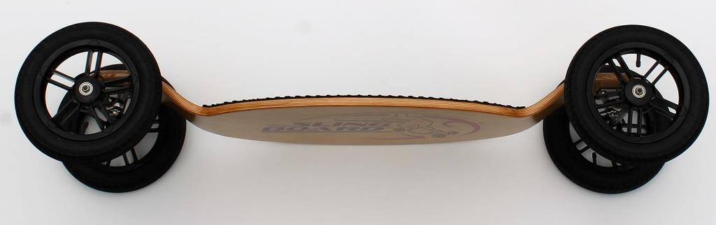
2 Thank you for selecting the SlingBoard! Table of Contents WARNINGS!!... 3 SAFETY PRECAUTIONS!!... 3 SET UP... 4 FLAT TIRE REPAIR... 9 PARTS DIAGRAMS...11 SLINGBOARD PARTS LIST...13 Page 2 of 13

3 WARNING!! Improper use of this product may lead to property damage, serious bodily injury, or death! Users must read and follow all instructions and safety precautions carefully. Users are responsible for all consequences caused by not following these instructions. Concept Evolution, Inc. does not bear legal liability for users improper operation in accordance with the law. The SlingBoard products were created for fitness purposes only, specifically flat distance land paddling. Do not use SlingBoard products for commuting or transportation, doing so in areas with pedestrians, high elevations, or where automobiles travel may cause property damage, injury or death to the rider or bystanders. SAFETY PRECAUTIONS Do not SlingBoard in areas where skateboarding is illegal, only SlingBoard in safe open areas like parks or trails where skateboarding is permitted. Always wear protective gear when SlingBoarding. This includes a well fitted helmet, wrist guards, knee pads, elbow pads, and athletic sneakers. Be sure to wear a helmet that meets or exceeds the safety standards of the U.S Consumer Product Safety Commission (CPSC), and does not interfere with your movement, vision, or hearing when riding. Please note the SlingBoard weight limit of 275 lbs. and do not ride if your weight exceeds that limit. For your safety, do not SlingBoard if you are pregnant. SlingBoarding is not recommended for children under the age of 12. Inspect your SlingBoard and SlingStick before every ride; look for problems that may need repair. Get professional help if needed to repair any damaged parts before you ride to prevent injury. Always survey the area before you SlingBoard, inspecting surfaces for potholes, rocks, and other debris. Avoid any areas where those are found to avoid injury. Never SlingBoard in the dark, or in wet slippery conditions. SlingBoard on smooth even surfaces to maintain the most control, pavement is optimal. Never ride with more than one person on a SlingBoard. Do not SlingBoard over ramps, as doing so may cause serious injury. Page 3 of 13

4 Do not attempt tricks or stunts on your SlingBoard as doing so may cause serious injury. Do not SlingBoard under the influence of any substances that may impair your vision, decision making, reaction time, or movement. Do not get distracted while riding your SlingBoard with actions such as answering your phone, listening to music in headphones, or engaging in any other activities. Learn slowly and don t take chances by SlingBoarding faster than your experience allows, or faster than is safe for the conditions. Do not make modifications or use non-slingboard parts with SlingBoard products, it will affect the performance, void the warranty, and may cause serious injury. Store your SlingBoard products safely and do not leave them outdoors exposed to the sun or rain. SET UP Tools Required: - 14mm deep socket wrench - Bicycle type air pump 1. Carefully remove the SlingBoard Deck and wheels from the box and packaging. All parts are displayed and labeled in the Parts Diagrams and List at the back of these instructions for your reference. 2. Inspect each Wheel (4) to make sure that each tire is well seated and centered in each of the rims. You may do this by holding the Wheel up and visually inspecting both sides where the tire tucks into the rim. Make sure that it is fully seated into the rim all the way around that area without any bulges or misalignment. If you see that it is misaligned or bulged out in any area you may push it in to seat properly with your fingers. Do this for all four (4) wheels to help ensure that the tires inflate properly. Page 4 of 13


5 3. Next remove the air fill stem cap from one of the tires and use a bicycle air pump to inflate, attach the air pump as shown below. 4. Inflate the tire slowly and take time in between each pump to make sure that the tire is still well seated and centered on the rim, if not adjust as needed per step 2. Inflate the tube to 35 PSI for best performance; do not overinflate as doing so could cause damage to the tire and injury. Inflate all four (4) wheels to the proper pressure then hand thread the air fill stem caps back onto all four (4) wheels. Page 5 of 13


6 5. At the end of each Truck Axle where each Wheel is attached are two (2) Axle Washers and one Axle Nut for the Wheel assembly. Locate these parts. 6. Remove one of Axle Washers and the Axle Nut from one of the Axle ends and set them aside, leave one Axle Washer on and push it in as far as possible. Next slide one of the wheels onto the Axle end and push it in as far as possible toward that Axle Washer. Page 6 of 13
7 7. Next slide the other Axle Washer onto the end of that Axle and in toward the Wheel. Then hand thread the Axle Nut for that Wheel onto the end of that Axle. 8. Next use a 14mm deep socket wrench to tighten that Axle Nut further onto the Axle threads. Tighten it in until it starts to feel snug. Spin the wheel to see if it spins freely, if so then that Wheel is properly installed. If the Wheel is restricted and does not spin freely then unthread that Axle Nut by 1/4 turn and spin it again to check. Repeat this until the Wheel spins freely. Then repeat for the three other wheels. Page 7 of 13


8 9. Next turn the SlingBoard over to adjust the Kingpin bolts. Locate the Kingpin bolt in each Truck. 10. It is recommended that first time SlingBoarders start with the Kingpin bolt tight, as this will keep the steering tight and make it easier to control the SlingBoard. Experienced SlingBoarders may skip this step if they prefer their trucks and steering looser. To tighten the steering use a 14mm deep socket wrench to tighten down the Kingpin bolt. Tighten it down until it is snug, then back it out 1/4 turn. 11. Test this Kingpin setting by standing on the SlingBoard and leaning side-to-side to see if you are able to tilt the SlingBoard and control it well. If the steering is too tight then back the Kingpin bolt out another 1/4 turn and test again. Do this until you can steer the SlingBoard with good control. Once you are a more comfortable and experienced rider you may back the Kingpin bolts out further for more dramatic steering with deeper and tighter turns. Your SlingBoard is now ready to ride! Page 8 of 13


9 FLAT TIRE REPAIR Tools Required: - 14mm deep socket wrench - Bicycle type air pump - Phillips head screwdriver - Flat head screwdriver 1. Remove the Axle Nut and outside Axle Washer securing the Wheel with the damaged tube or tire using a 14mm deep socket wrench. 2. Slide the wheel off of the Axle and remove the air fill stem cap. Next use the head of a Philips screwdriver to gently press the air release pin at the center of the air fill stem. Press it down until you hear the air no longer releasing. Page 9 of 13


10 3. Next you will pull the tire sideways to remove it from the rim. You may use a flat head screwdriver to very carefully pry the tire off. Take great care not to damage the rim or tire when prying it off. 4. Then remove the tube from the inside of the tire if damaged. Replace the tire and/or tube if damaged. Insert the new tube into the tire and take care to lay it inside evenly. Align the air fill stem with the air fill hole in the rim, then pull the new tire/tube onto the rim from the side. Take care to make sure that the air fill stem stays straight as you pull it through the rim. Next go back to Step 2 in the SET UP process on page 5 of these instructions to finish out the steps for inflating and installing that wheel back onto the SlingBoard. The wheel has been repaired. Page 10 of 13

11 PARTS DIAGRAMS Page 11 of 13

12 Page 12 of 13
13 SLINGBOARD PARTS LIST Name (# of parts in finished product) x Description Part # Parts Wheels (4) x 12 Pneumatic SBW1 Traction Pad (1) x EVA Foam TP1 Trucks (2) x 15 Custom Red - SBTR1 Blue - SBTB1 Truck Riser Pads (2) x 2 1/8x3 1/8 TRP1 Deck (1) x 48x16 - Basic Red SBDBR1 Basic Green - SBDBG1 Skull Design - SBDSD1 Koi Design - SBDKD1 Hardware Truck Bolts (8) x SS Machine Bolts #10-24*1 ½ TB1 Truck Washers (8) x SS Flat Washers ½ OD TW1 Truck Nuts (8) x SS Lock Nuts #10-24 TN1 Axle Nuts - (4) x 9mm ID lock nuts - AN1 Axle Washers - (8) x 5/8 OD flat washer - AW1 SB Customer Instructions (1) x Printed Instructions SBI CONTACT US info@slingboarding.com Phone: Page 13 of 13
AB CRUNCH SIT UP BENCH MODEL# 8642AB PRODUCT MANUAL - VERSION
 AB CRUNCH SIT UP BENCH MODEL# 842AB PRODUCT MANUAL - VERSION 01.18.0 FOR AGES: WEIGHT LIMIT: 20 Lbs 3 Kgs TO BUILD: 13+ 1 X TOOLS NEEDED: CUSTOMER SERVICE GQBrands.com CustomerService@GQBrands.com 1-8-498-29
READ ME FIRST. Touchstone TV Lift
 Whisper Lift II PRO 2 READ ME FIRST 1. After completing the unpacking and uncrating of the cabinet, you will find the Owner s Manual, TV, installation hardware, and the wireless remote all together and
Toughsat Flyaway Users Manual
 Toughsat Flyaway Users Manual TOUGHSAT FLYAWAY USERS MANUAL V.1.6 September 2012 Important warning regarding your TOUGHSAT System All power to the system (controller, modem, external network devices) MUST
TV Lift System Model CL-65 Installation Instructions
 TV Lift System Model CL-65 Installation Instructions Contact: Support@Nexus21.com Toll Free: (866) 500-5438 Phone: (480) 951-6885 Fax: (480) 951-6879 Revised: 01/17/17 Below is a parts list describing
MF-4000 WEIGHT BENCH OWNER S MANUAL
 MF-4000 WEIGHT BENCH OWNER S MANUAL Product may vary slightly from the item pictured due to model upgrades Read all instructions carefully before using this product. Retain this owner s manual for future
INSTALLATION GUIDE. Axle Weighing Truck Scale. 60,000 lb x 20 lb Factory Calibrated Includes Pre-interfaced Wireless Remote LED Scoreboard Displays
 INSTALLATION GUIDE 60,000 lb x 20 lb Factory Calibrated Includes Pre-interfaced Wireless Remote LED Scoreboard Displays V 1.0 OVERVIEW TOOLS REQUIRED Forklift and block Prybar Wrenches: #8 allen wrench,
SPARK. Swing Manual READ MANUAL FIRST. Version 1.2
 SPARK Swing Manual READ MANUAL FIRST Version. Site Checks Site Checks You should setup this swing set in an environment which:. is clear from walls, structures, fences and anything that will cause injuries..
WID-DL74 WID-DL74 BLP WID. Designed for. Installation guide for workitdesk interactive table for. BrightLink Pro
 WID-DL74 WID-DL74 BLP WID Designed for BrightLink Pro Installation guide for workitdesk interactive table BrightLink Pro for Mounting the table unit 1 Unpack boxes 1 of 4 (Mobile base) and 2 of 4 (Motorized
Move & Store Cart CONTENTS. Assembly Instructions
 Assembly Instructions Move & Store Cart CONTENTS Safety Precautions.................................. 2 Warranty.......................................... 2 Important User Information............................
In-Ceiling Electric Motorized Front Projection Screen Evanesce Series. User s Guide
 In-Ceiling Electric Motorized Front Projection Screen Evanesce Series User s Guide Important Safety & Warning Precautions Make sure to read this user s guide and follow the procedures below. Caution: The
BN-6 CHIN UP ATTACHMENT OWNER S MANUAL
 BN-6 CHIN UP ATTACHMENT OWNER S MANUAL Product may vary slightly from the item pictured due to model upgrades Read all instructions carefully before using this product. Retain this owner s manual for future
USER S MANUAL. Save this manual for future reference. For a digital version of this manual, visit
 TM USER S MANUAL Save this manual for future reference. For a digital version of this manual, visit www.mylifter.com/installation. 4 5 TABLE OF CONTENTS 4 INSTALLING THE PULLEY SYSTEM FOR LIFTING 100
75 Elliptical Antenna System
 Instruction and Assembly Manual 75 Elliptical Antenna System 7291 NW 74th Street Miami, FL 33166 GlobeCast Technical Service: (888) 988-5288 Manufactured By: 2002 Channel Master LLC Printed in U.S.A. 8000915-02
Installation Guide OvalSox TM Cable
 Installation Guide OvalSox TM Cable Thank you for selecting a DuctSox System. This guide will be helpful for the installation of an OvalSox Cable System. Sections of fabric will be labeled, assembled,
Step 1. 1x NXT Ultrasonic Sensor
 Start with the build completed in Lesson 3 of the TETRIX Getting Started Guide. Step 1 involves removing an element from the model. This element will be reattached later. Parts to be Removed Step 1 1x
2000 Series Weather Stations Analog Temperature / RH Sensor Upgrade Kit PRODUCT MANUAL KIT # 3613WDU
 2000 Series Weather Stations Analog Temperature / RH Sensor Upgrade Kit PRODUCT MANUAL KIT # 3613WDU 1 The 3613WDU Analog Temperature / RH Sensor Upgrade Kit is used to upgrade Watchdog 2000 Series Weather
3. Electronics and MMU2 unit assembly
 Written By: Jakub Dolezal 2018 manual.prusa3d.com/ Page 1 of 34 Step 1 Tools necessary for this chapter Please prepare tools for this chapter: 2.5mm Allen key for M3 screws 2mm Allen key for nut alignment
In-Wall Control Mount for ipod Touch
 In-Wall Control Mount for ipod Touch INTRODUCTION The Mirage KP-iOS is an in-wall system that allows ipod touch (4th generation) to become a semi-permanent fixture in your wall. The system allows you to
A449-6S 70 CENTIMETER FM YAGI ANTENNA MHz
 ASSEMBLY AND INSTALLATION A449-6S 70 CENTIMETER FM YAGI ANTENNA 440-450 MHz COMMUNICATIONS ANTENNAS 951425 (7/93) WARNING THIS ANTENNA IS AN ELECTRICAL CONDUCTOR. CONTACT WITH POWER LINES CAN RESULT IN
C 303W-RF Tri-element Array Microphone Instructions
 C 303W-RF Tri-element Array Microphone Instructions C 303W-RF Installation Instructions Packaging C 303W microphone Enclosure with 2.5 Metre (8ft) cae Link cable Cable gland It may be easier to remove
Vibratory Deck Sieves 15 in. (380 mm)
") Instruction Sheet P/N 1604433-01 Vibratory Deck Sieves 15 in. (380 mm) Introduction This instruction sheet covers the vibratory deck sieves listed in the following tables. 15-Inch Deck Sieves with 2.5
Instruction Sheet P/N 1604433-01 Vibratory Deck Sieves 15 in. (380 mm) Introduction This instruction sheet covers the vibratory deck sieves listed in the following tables. 15-Inch Deck Sieves with 2.5
Step 1. 1x Single-Servo Motor Bracket. 1x L Bracket
 Extensions TETRIX Getting Started Guide Step 1 1x Single-Servo Motor Bracket 1x L Bracket 3x 5/16" SHCS 3x Kep Nut Tips The 7/64" and 5/64" hex keys will be used in this model. Ensure that the teeth of
2178-L/S Series Fiber Optic Splice Case with Gasket
 2178-L/S Series Fiber Optic Splice Case with Gasket Instructions for: 2178-S Splice Case 2178-LS Splice Case 2178-LL Splice Case 2181-LS Cable Addition Kit May 1997 34-7041-9949-5-A 1 Table of Contents
MY-HITE ADJUSTABLE TABLE
 MY-HITE ADJUSTABLE TABLE Corner T Leg Base Model Number : FCNAHBT Please Read Instructions Before Use ASSEMBLY INSTRUCTIONS ALL WORKSTYLES WELCOME Thank you for choosing Friant. We appreciate the trust
Power Rack with Lat Pull
 Power Rack with Lat Pull BD-7 Owner's Manual VA0900 D SAFETY & PRECAUTIONS IMPORTANT: READ ALL PRECAUTIONS CAREFULLY BEFORE USING THIS PRODUCT. RETAIN OWNER'S MANUAL FOR FUTURE REFERENCE. Note: This item
PRJTPFL inch PRJTPFL inch PRJTPFL inch. Fixed Wall Mount Projector Screen. Universal Home/Office Projector Viewing Display
 PRJTPFL102-100 - inch PRJTPFL112-110 - inch PRJTPFL122-120 - inch Fixed Wall Mount Projector Screen Universal Home/Office Projector Viewing Display Be sure to read this manual before use so you will know
DLP ANTENNA INSTRUCTION MANUAL. Dielectric LLC 22 Tower Road Raymond, Maine Phone:
 DLP ANTENNA INSTRUCTION MANUAL Dielectric LLC 22 Tower Road Raymond, Maine 04071 Phone: 800-341-9678 TABLE OF CONTENTS Section Title Page Warnings 1 Return Policy. 1 Factory Tests... 1 Antenna Description....
ACCESSORIES MANUAL PART NUMBER: PRODUCT REVISION: 1 TNP100. Tilt N Plug Interconnect Box USER'S GUIDE
 MANUAL PART NUMBER: 400-0091-001 PRODUCT REVISION: 1 TNP100 Tilt N Plug Interconnect Box USER'S GUIDE INTRODUCTION Your purchase of the TNP100 Tilt N Plug Interconnect Box is greatly appreciated. We are
1.8 METER SERIES 1183 Az/El MOUNT ANTENNA SYSTEM
 REVISION G January 11, 2002 ASSEMBLY MANUAL 1.8 METER SERIES 1183 Az/El MOUNT ANTENNA SYSTEM PRODELIN CORPORATION 1500 Prodelin Drive Newton NC 28658 1.8 METER SERIES 1183 Az/El MOUNT ANTENNA SYSTEM G
INVERSION TABLE MODEL# 8514IT PRODUCT MANUAL - VERSION
 INVERSION TABLE PRODUCT MANUAL - VERSION 02.16.02 FOR AGES: 13+ WEIGHT LIMIT: 220 Lbs 100 Kgs ADULT(S) NEEDED: TOOLS NEEDED: WARNING/ADVERTENCIA CUSTOMER SERVICE Do not allow more than one person one this
Installation Manual SaVi Note Underwater LED Light
 Installation Manual SaVi Note Underwater LED Light Model Numbers SAVI-NOTE7, SAVI-NOTE0 Table of Contents Safety Precautions...2 SaVi Note Install Instructions...3- M Instructions...- Warnings READ AND
ROLL-A-STRIKE. Assembly Instructions Model CONTACT INFO. Hours. Technical Support Monday to Friday (9am to 5pm EST)
") PATENT - www.eastpointsports.com ROLL-A-STRIKE TM ELECTRONIC BOWLING Assembly Instructions Model --286 CONTACT INFO ASSEMBLY REQUIRED Hours Technical Support Monday to Friday (9am to 5pm EST) Email us
PATENT - www.eastpointsports.com ROLL-A-STRIKE TM ELECTRONIC BOWLING Assembly Instructions Model --286 CONTACT INFO ASSEMBLY REQUIRED Hours Technical Support Monday to Friday (9am to 5pm EST) Email us
1-Touch Vibratory Sieve Shaker SS-10
 1-Touch Vibratory Sieve Shaker SS-10 Safety Instructions WARNING!! This machine operates on electric current. Improper operation could result in electrical shock, electrocution, or an explosion! 1. ALWAYS
#YourGearUpgraded. TV Stand Model EGTV1 INSTRUCTION MANUAL
 #YourGearUpgraded TV Stand Model EGTV1 INSTRUCTION MANUAL IMPORTANT SAFETY INSTRUCTIONS. READ ENTIRE MANUAL PRIOR TO USE. SAVE These INSTRUCTIONS Yea, the boring stuff...... but read it, so you don t jack
Metal and Glass TV Stand for TVs up to 65 or 110 lbs. NS-HMG1856
 USER GUIDE Metal and Glass TV Stand for TVs up to 65 or 110 lbs. NS-HMG1856 SAFETY INFORMATION AND SPECIFICATIONS...2 PACKAGE CONTENTS: PARTS...3 PACKAGE CONTENTS: HARDWARE...4 ASSEMBLY INSTRUCTIONS...5
INSTALLATION INSTRUCTIONS RGB / RGBW 24V LED TAPE
 LLI-LCC4.4W LLI-LCCW4.4W LLI-LCCW5.8W **DANGER: Prior to installation, disconnect power at the source.** Make sure you have all components listed below: LED tape 24VDC Power Supply Connectors (if creating
USER MANUAL. DE-1 Police-light. CAUTION! Keep this device away from rain and moisture! Unplug mains lead before opening the housing!
 USER MANUAL DE-1 Police-light CAUTION! Keep this device away from rain and moisture! Unplug mains lead before opening the housing! For your own safety, please read this user manual carefully before you
A CENTIMETER FM YAGI ANTENNA MHz
 ASSEMBLY AND INSTALLATION A449-70 CENTIMETER FM YAGI ANTENNA 440-450 MHz COMMUNICATIONS ANTENNAS 951424 (10/91) WARNING THIS ANTENNA IS AN ELECTRICAL CONDUCTOR. CONTACT WITH POWER LINES CAN RESULT IN DEATH
DLMP Installation Instructions
 DLMP Installation Instructions Tools Needed Posidrive No.3 Screwdriver Large Flat Head Screwdriver 2x 10mm Spanner 1x 13mm Spanner Ø8mm Drill Ø6mm Drill Kit Contents [ ] 1x Tube 2.5M long 17420 [ ] 2 x
DLMP-45/45R Installation Instructions
 DLMP-45/45R Installation Instructions Tools Needed Posidrive No.3 Screwdriver Large Flat Head Screwdriver 2x 10mm Spanner 1x 13mm Spanner Ø8mm Drill Ø6mm Drill Kit Contents [ ] 1x Tube 2.5M long 17420
Growmaster Assembly Instructions
 Growmaster ssembly Instructions Item No. Part Sect. Ref. Size mm Quantity Item No. Part Sect. Ref. Size mm Quantity 1001 15 M6 x 12 86x 97x 108x 1067 6 295 16 M6 9 10 113x 1301 7 30 9x 1 13x 5 7 3.5 x
Caution. Hanging the Screen:
 Installation Instructions for Laminar and Laminar XL Projection Screens Caution 1. Read Instructions through completely before proceeding; keep them for future reference. Follow these instructions carefully.
Technical Information Bulletin
 June 4, 2001 #TIB0003 Units Affected: Model Serial Numbers Model Serial Numbers SVT-2PRO T2PDxxxxxxxxx SVTAV AXVDxxxxxxxxx ATLDxxxxxxxxx BJIDMAxxxxxxx SVT-2PROJ T2PJxxxxxxxxx SVTAVJ BAHJxxxxxxxxx ATLJxxxxxxxxx
2.4 METER SERIES 1250 ANTENNA SYSTEM
 June 1,2009 Revision B Assembly Manual 2.4 METER SERIES 1250 ANTENNA SYSTEM General Dynamics SATCOM Technologies 1500 Prodelin Drive Newton NC 28658 2.4 Meter 2 Piece Az/El Installation Instructions B
TECHNICAL BULLETIN. Ref. No. P (Repl P-03-11)
") 0 TECHNICAL BULLETIN August 2006 Ref. No. P-06-01 (Repl P-03-11) Guidelines for Selection of Replacement Tires --Including Substitute Tire Sizes-- With Important Safety Information To ensure the same performance
0 TECHNICAL BULLETIN August 2006 Ref. No. P-06-01 (Repl P-03-11) Guidelines for Selection of Replacement Tires --Including Substitute Tire Sizes-- With Important Safety Information To ensure the same performance
AT-AUTO (tm) QRO Keyline Upgrade Kit Installation Manual
 QRO Keyline Upgrade Kit Installation Manual") AT-AUTO (tm) QRO Keyline Upgrade Kit Installation Manual P.O. Box 341543 Beavercreek, Ohio 45434 5 September, 2015 Copyright 2015 ii Contents 1 Introduction 2 1.1 General Description and Purpose........................
AT-AUTO (tm) QRO Keyline Upgrade Kit Installation Manual P.O. Box 341543 Beavercreek, Ohio 45434 5 September, 2015 Copyright 2015 ii Contents 1 Introduction 2 1.1 General Description and Purpose........................
ACCESSORIES MANUAL PART NUMBER: TNP500. Universal Tilt N Plug Interconnect Box USER'S GUIDE
 MANUAL PART NUMBER: 400-0091-003 TNP500 Universal Tilt N Plug Interconnect Box USER'S GUIDE INTRODUCTION Your purchase of the TNP100 Tilt N Plug Interconnect Box is greatly appreciated. We are sure you
WINEGARD INSTALLATION MANUAL. Model GM Carryout Ladder Mount for mounting pipes with outer diameters between 1 to 1-1/8
 WINEGARD INSTALLATION MANUAL Model GM-3000 Carryout Ladder Mount for mounting pipes with outer diameters between 1 to 1-1/8 WARNING: DO NOT USE THE LADDER MOUNT AS A STEP! NOT INTENDED FOR USE WITH THE
PLL1920M LED LCD Monitor
 PLL1920M LED LCD Monitor USER'S GUIDE www.planar.com Content Operation Instructions...1 Safety Precautions...2 First Setup...3 Front View of the Product...4 Rear View of the Product...5 Installation...6
Electric Wall/Ceiling Projection Screen Saker Tab-Tension Series User s Guide
 Electric Wall/Ceiling Projection Screen Saker Tab-Tension Series User s Guide Important Safety & Warning Precautions Make sure to read this user s guide and follow the procedures below. Caution: The screen
DEM 9ULNACK 3.4 GHz. PHEMT LNA amplifier complete kit assembly guide
 DEM 9ULNACK 3.4 GHz. PHEMT LNA amplifier complete kit assembly guide SPECIFICATIONS Noise Figure: < 0.8 db Gain: > 15 db Frequency Range: 3400-3500 MHz Input Voltage: 7-16 VDC Description: The 9ULNACK
Installing a Wire Mesh Pulling Grip on All-Dielectric DX Armored Fiber Optic Cables
 revision history Issue Date Reason for Change Related literature SRP-004-136 Accessing All-Dielectric DX Armored Fiber Optic Cables Admonishments 1. General This procedure provides instructions for installing
Satellite Dish Installation Manual (Ver. 2) 1
 1") Satellite Dish Installation Manual Provided by DiscoverNet, Inc. Satellite Dish Installation Manual (Ver. 2) 1 Table of Contents Section 1: Introduction Page 3 Section 2: Recommended Tools and Materials
Satellite Dish Installation Manual Provided by DiscoverNet, Inc. Satellite Dish Installation Manual (Ver. 2) 1 Table of Contents Section 1: Introduction Page 3 Section 2: Recommended Tools and Materials
User Guide SiriUS ConneCt tuner
 User Guide Sirius ConneCt TUNER Congratulations on your purchase of the SIRIUS Connect SCH1P2 Satellite Radio Tuner! Your new SCH1P2 SIRIUS Connect Satellite Radio Tuner is designed to work with SIRIUS-Ready
Install Guide Incredible Technologies, Inc. All Rights Reserved
 Install Guide 2015 Incredible Technologies, Inc. All Rights Reserved Preface Using this Guide The following icons are used to highlight specific areas of interest and to indicate when extreme caution is
Revella Gazebo. Item# L-GZ806PST-A2
 Revella Gazebo Item# L-GZ806PST-A2 Congratulations on your purchase of Revella Gazebo. Our clear, easy to follow, step-by-step instructions will guide you through the assembly process from start to finish.
TECHNICAL GUIDE. TOUGH GUN ThruArm G2 Series Robotic MIG Guns for FANUC Robots 100iC, 100iC-6L, 120iC, 120iC-10L INSTALLATION MAINTENANCE
 TECHNICAL GUIDE TOUGH GUN ThruArm G2 Series Robotic MIG Guns for FANUC Robots 100iC, 100iC-6L, 120iC, 120iC-10L INSTALLATION MAINTENANCE TECHNICAL DATA OPTIONS EXPLODED VIEW & PARTS LIST ORDERING INFORMATION
Issue date : 9/11/00. Rogue Audio Tempest Vacuum Tube Integrated Amplifier. Owners Manual. Vacuum Tube Amplifiers
 Issue date : 9/11/00 Rogue Audio Tempest Vacuum Tube Integrated Amplifier Owners Manual Vacuum Tube Amplifiers TABLE OF CONTENTS 1) Introduction 1 2) Setting up your amplifier 1 3) Using an external preamplifier
Desk Mount Articulating Dual Monitor Arm with Cable Management & Height Adjust
 Desk Mount Articulating Dual Monitor Arm with Cable Management & Height Adjust ARMDUAL *actual product may vary from photos DE: Bedienungsanleitung - de.startech.com FR: Guide de l'utilisateur - fr.startech.com
NewScope-7A Operating Manual
 2016 SIMMCONN Labs, LLC All rights reserved NewScope-7A Operating Manual Preliminary May 13, 2017 NewScope-7A Operating Manual 1 Introduction... 3 1.1 Kit compatibility... 3 2 Initial Inspection... 3 3
Installation Manual Original Instructions - IW4001
 Installation Manual Original Instructions - IW4001 Installation Manual 1 General Operator and Supervisor Information Signal Word Definition Signal Word Panel Table of Contents Operator and Supervisor Information
1.2 GHz GS7000 Node RF Split Upgrade Application Note
 1.2 GHz GS7000 Node RF Split Upgrade Application Note Overview Introduction Cable operators have experienced an exponential rise in the requirement for more reverse path bandwidth due to the popularity
Safety Rules Parts Check Lists and Photos Cable Diagrams for Various Crane Configurations Step by Step Instructions Tips for Packaging and Storage
 EZ CRANE USER MANUAL INCLUDED INSIDE Safety Rules Parts Check Lists and Photos Cable Diagrams for Various Crane Configurations Step by Step Instructions Tips for Packaging and Storage WATCH THE INSTRUCTIONAL
Z100 / Z300 Z500 Z700 OWNER S MANUAL PLEASE CAREFULLY READ THIS ENTIRE MANUAL BEFORE OPERATING YOUR NEW ELLIPTICAL!
 Z100 / Z300 Z500 Z700 OWNER S MANUAL PLEASE CAREFULLY READ THIS ENTIRE MANUAL BEFORE OPERATING YOUR NEW ELLIPTICAL! Table of Contents Product Registration. 2 Important Safety Instructions 3 Important Electrical
VT320X Large Screen Outdoor LCD
 Solutions for Demanding Applications VARTECH S Y S T E M S I N C. Industrial CRT and Flat Panel Displays VT320X Large Screen Outdoor LCD User s Guide Read these instructions completely before attempting
INSTRUCTION MANUAL MUSICAL LASER LIGHT SHOW TM
 INSTRUCTION MANUAL MUSICAL LASER LIGHT SHOW TM WARNINGS When using this MUSICAL LASER LIGHT SHOW TM, basic safety precautions should always be followed to reduce the risk of fire, electric shock, and personal
PLL2210MW LED Monitor
 PLL2210MW LED Monitor USER'S GUIDE www.planar.com Content Operation Instructions...1 Safety Precautions...2 First Setup...3 Front View of the Product...4 Rear View of the Product...5 Quick Installation...6
SmartMix Manual V5350A
 SmartMix Manual V5350A 3 Table of contents Overview................................................... 4 Features.................................................... 4 Scope of delivery................................................
PL2410W LCD Monitor USER'S GUIDE.
 PL2410W LCD Monitor USER'S GUIDE www.planar.com Content Operation Instructions...1 Safety Precautions...2 First Setup...3 Front View of the Product...4 Rear View of the Product...5 Quick Installation...6
Indoor/Outdoor Security System with Quad Monitor User s Manual
 Indoor/Outdoor Security System with Quad Monitor User s Manual 4919539 Important! Please read this booklet carefully before installing or using these units. WARNING - These units should ONLY be opened
Challenges. TETRIX Getting Started Guide STEM Challenge Building Guide. Step 1. Parts Needed. Tips
 Note: The Arm and Gripper Extension has been recommended as an initial build to complete the STEM Challenge. The STEM Challenge Sample Program and Programming Guide have been created to work effectively
OPERATION AND MAINTENANCE MANUAL
 OPERATION AND MAINTENANCE MANUAL SERIAL NUMBER CUSTOMER: SALES REP.: CONTENTS Mixer Installation / Assembly / Dimension Drawings Safety... 1 Customer Service Contact... 1 Initial Inspection... 2 Installation...2
Remote Tuner Options for the DXE-MBVE-1 Vertical Antenna
 Remote Tuner Options for the DXE-MBVE-1 Vertical Antenna DXE-MBVE-1UGBRT3 for the MFJ-993BRT 300 Watt Remote Tuner DXE-MBVE-1UGBRT4 for the MFJ-994BRT 600 Watt Remote Tuner DXE-MBVE-1UGRT8 for the MFJ-998RT
Replacing the PanelMate epro PS, PanelMate epro PS Classic, PanelMate epro PS EE, and PanelMate epro PS OD 7685x-15xx Series Backlight Assembly
 Introduction Replacing the PanelMate epro PS, PanelMate epro PS Classic, PanelMate epro PS EE, and PanelMate epro PS OD 7685x-15xx Series Assembly Instruction Leaflet IL04802009E Effective September 2008
3M Better Buried Compound Compression Closure System
 3M Better Buried Compound Compression Closure System Instructions March 2016 78-0015-2948-2-A Contents: 1.0 General...3 2.0 Kit Contents...3 3.0 Closure Selection Guide...4 4.0 LHS End Cap Installation...5
C 303-RF Tri-element Array Microphone Instructions
 C 303-RF Tri-element Array Microphone Instructions C 303-RF Installation Instructions Packaging C 303 microphone Enclosure with 2.5 Metre (8ft) cae Link cable Cable gland It may be easier to remove the
Xenon lamp for HDX. Installation manual
 Xenon lamp for HDX Installation manual R5905147/01 31/05/2012 Barco nv Entertainment Division Noordlaan 5, B-8520 Kuurne Phone: +32 56.36.82.11 Fax: +32 56.36.883.86 Support: www.barco.com/esupport Visit
3M Fiber Optic Splice Closure 2178-XL & 2178-XL/FR
 3M Fiber Optic Splice Closure 2178-XL & 2178-XL/FR 3M Cable Addition Kit 2181-XL and 2181-XL/FR Instructions September 2017 78-8130-5055-2-M 2 September 2017 78-8130-5055-2-M 1.0 Kit Contents 2.0 General...
Be sure to check the camera is properly functioning, is properly positioned and securely mounted, every time you operate your vehicle.
 Please read all of the installation instructions carefully before installing the product. Improper installation will void manufacturer s warranty. The installation instructions do not apply to all types
3M Fiber Optic Splice Closure 2178-XL & 2178-XL/FR 3M Cable Addition Kit 2181-XL and 2181-XL/FR
 3M Fiber Optic Splice Closure 2178-XL & 2178-XL/FR 3M Cable Addition Kit 2181-XL and 2181-XL/FR Instructions July 2010 3 1.0 Contents 1.0 General...3 2.0 Kit Contents...3 3.0 Cable Preparation...4 4.0
ipad mini 4 LTE Right Cellular Antenna Replacement
 ipad mini 4 LTE Right Cellular Antenna Replacement Replace the right cellular antenna in an ipad mini 4 LTE. Written By: Evan Noronha ifixit CC BY-NC-SA www.ifixit.com Page 1 of 22 INTRODUCTION Follow
Z100 / Z300 Z500 Z700 OWNER S MANUAL PLEASE CAREFULLY READ THIS ENTIRE MANUAL BEFORE OPERATING YOUR NEW ELLIPTICAL!
 Z100 / Z300 Z500 Z700 OWNER S MANUAL PLEASE CAREFULLY READ THIS ENTIRE MANUAL BEFORE OPERATING YOUR NEW ELLIPTICAL! Table of Contents Product Registration.. 2 Important Safety Instructions 3 Important
CM MTC PARTS LIST
 8650 Enterprise Drive, Peosta IA 52068-0050 319-556-7484 / Fax 319-556-1235 CM-2400-0MTC PARTS LIST ENGINE OIL GRADE: ENGINE OIL CAPACITY: PUMP OIL: PUMP OIL CAPACITY: NOZZLE SIZE: 30W 21 oz. MI-T-M #AW-4085-0016
Remote Tuner Options for the DXE-MBVE-5A Vertical Antenna DXE-MBVE-5UGBRT3 for the MFJ-993BRT 300 Watt Remote Tuner
 Remote Tuner Options for the DXE-MBVE-5A Vertical Antenna DXE-MBVE-5UGBRT3 for the MFJ-993BRT 300 Watt Remote Tuner DXE-MBVE-5UGBRT4 for the MFJ-994BRT 600 Watt Remote Tuner DXE-MBVE-5UGBRT3-4- INS-Revision
3M Distribution Box (DDB)
") 3M Distribution Box (DDB) Merged Copper and Fiber Pole/Post Mount Enclosure Installation Instructions November 2015 78-0015-2736-1-A 2 November 2015 78-0015-2736-1-A Contents 1.0 General 2.0 Enclosure
3M Distribution Box (DDB) Merged Copper and Fiber Pole/Post Mount Enclosure Installation Instructions November 2015 78-0015-2736-1-A 2 November 2015 78-0015-2736-1-A Contents 1.0 General 2.0 Enclosure
Operation and Maintenance Guide Electric Needle Scalers
 Operation and Maintenance Guide Electric Needle Scalers Models Covered Model Number ENS100V ENS200V Electric Needle Scaler, 110V-1ph Electric Needle Scaler, 220V-1ph Description IMPA Number 59 12 01 59
iphone 7 Plus LCD Screen and Digitizer Replacement
 iphone 7 Plus LCD Screen and Digitizer Replacement Replace just the bare front panel not including the home/touch ID sensor, front-facing camera and sensor cable, or earpiece speaker in an iphone 7 Plus.
2178 Fiber Optic Splice Case and 2181 Cable Addition Kit
 2178 Fiber Optic Splice Case and 2181 Cable Addition Kit Instructions January 1994 Issue 1, 34-7029-6387-6 1 2 Contents: 1.0 General... 4 2.0 Specifications... 4 3.0 Kit Contents... 5 SECTION 1: 2178 Splice
Section 2 Normal Procedures
 1 Section 2 Normal Procedures The Pro Flight Trainer Evolution BL is a HID USB Device that Plug & Play to any compatible Operating System. It will be recognized as a USB Input Device with 5 axis, 6 buttons,
ACCESSORIES MANUAL PART NUMBER: PRODUCT REVISION: 1 PNP202. Interconnect Box USER'S GUIDE
 MANUAL PART NUMBER: 400-0109-001 PRODUCT REVISION: 1 PNP202 Interconnect Box USER'S GUIDE INTRODUCTION Your purchase of the PNP202 Interconnect Box is greatly appreciated. We are sure you will find it
ASSEMBLY AND INSTALLATION 3 ELEMENT 6 METER BEAM
 ASSEMBLY AND INSTALLATION A50-3S 3 ELEMENT 6 METER BM COMMUNICATIONS ANTENNAS 951364 (12/94) WARNING THIS ANTENNA IS AN ELTRICAL CONDUCTOR. CONTACT WITH POWER LINES CAN RESULT IN DTH, OR SERIOUS INJURY.
Mitsubishi WD57734 DLP Chip Replacement
 Mitsubishi WD57734 DLP Chip Replacement Replace the DLP chip in your Mitsubishi WD57734. Written By: David Sylvester ifixit CC BY-NC-SA www.ifixit.com Page 1 of 10 INTRODUCTION This guide will detail the
Electric Motorized Projection Screen Spectrum Tab-Tension Series User s Guide
 Electric Motorized Projection Screen Spectrum Tab-Tension Series User s Guide Important Safety Precautions Make sure to read this user s guide and follow the procedures below prior to screen operation.
User Instructions. 16 SCB Sync Station.
 User Instructions 16 SCB Sync Station Contents Overview... 1 Specifications... 1 Compliance and approvals... 2 Safety instructions... 3 Set up... 4 How to charge multiple devices... 4 How to synchronize
Electric Wall/Ceiling Projection Screen Saker Series User s Guide
 Electric Wall/Ceiling Projection Screen Saker Series User s Guide Important Safety & Warning Precautions Make sure to read this user s guide and follow the procedures below. Caution: The screen s Black
Electric Motorized Projection Screen PowerMax Tension Series
 Electric Motorized Projection Screen PowerMax Tension Series User s Guide Important Safety & Warning Precautions Make sure to read this user s guide and follow the procedures below. Caution: The screen
Clarinet Assembling the Instrument
 Clarinet Assembling the Instrument 1. Have students take instrument cases to another area of the room and set the cases flat on a table. If no table is available, students should put cases on the floor
VPM2. Operator's Manual
 VPM2 Operator's Manual Whip Mix Corporation 361 Farmington Ave. P.O. Box 17183 Louisville, KY 40217-0183 USA 502-637-1451 800-626-5651 Fax 502-634-4512 www.whipmix.com Features The Whip Mix VPM2 is designed
ACADEMIC SUCCESS CENTER THE COLLEGE AT BROCKPORT STATE UNIVERSITY OF NEW YORK PROJECT NO
 SECTION 270536 - CABLE TRAYS FOR COMMUNICATIONS SYSTEMS PART 1 - GENERAL 1.1 RELATED DOCUMENTS A. Drawings and general provisions of the Contract, including General and Supplementary Conditions and Division
Setup Guide. Read me BefoRe unpacking!
 Setup Guide Read me BefoRe unpacking! Package Contents In The Replicator package The Replicator SD card (in The Replicator SD card slot) In the Accessory Box found within The Replicator frame Single or