SERVICE MANUAL CHASSIS CTS-AA
|
|
|
- Raymond Hall
- 6 years ago
- Views:
Transcription
1 SERVICE MANUAL CHASSIS CTS-AA
2 CONTENTS Page 1.- Technical specifications Connection Facilities Mechanical instructions Oscillograms Print board layout Electric Scheme Circuit description Small signal processing RGB ampliers Deflection Sound amplifier Power supply Microcontroller/Text Electrical adjustments Safety instructions List of abbreviations Service components 23 2
3 1. Technical specifications CHASSIS CTS - AA Mains voltage : V ± 10% AC; 50 Hz (±5%) Power cons. at 220V~ : 35W (14''), 50W(20''/21''), 5W (stand by) Aerial input impedance : 75S - coax Min. aerial input VHF : 30µV Min. aerial input UHF : 40µV Max. aerial input VHF/UHF : 180mV Pull-in range colour sync. : ± 300Hz Pull-in range horizontal sync. : Hz / Hz Pull-in range vertical sync. : ± 5 Hz Picture tube range : 14'' / 20'' /21'' : Mono: 25S 1W (14''). 16S 2W (20''/21'') TV Systems : PAL BG : PAL I : PAL BG / SECAM BGDK : PAL BGI / SECAM BGLL' Indications : On screen display (OSD) / menu : 1 LED RED. Dark in ON, bright in stand by, blinking with RC. VCR programs : 0 to 99 Tuning and operating system : VST UV1315A / IEC (VST) : VHFa: MHz : VHFb: MHz : UHF: MHz U1343A / IEC (VST) : UHF: MHz Local operating functions : Vol/Prog, +, -, contrast, colour and brightness. 2. Connection facilities Euroconector: 1 - Audio R (0V5 RMS / 1K ) CVBS 2 - Audio R (0V2-2V RMS / 10K ) CVBS 3 - Audio L ( 0V5 RMS / 1K ) CVBS ( 1Vpp 75S ). 4 - Audio 20 - CVBS ( 1Vpp/75S ). 5 - Blue 21 - Earthscreen. 6 - Audio L (0V2-2V RMS / 10K ). 7 - Blue (0V7pp/75S ). 8 - CVBS status 1 (0-2V int., 10-12V ext.). 9 - Green Green (0V7pp/75S ) Red Head phone: Red (0V7pp/75S ). 8S to 600S (32S 25mW) 16 - RGB status (0V to 0V4 int.) (1-3V ext. 75S ). 3
4 3. Mechanical instructions For the main carrier two service positions are possible (3.1). A: For faultfinding on the component side of the main carrier. B: For (de) soldering activities on the copper side of the main carrier. Position A can be reached by first removing the mains cord from it's fixation, then loosen the carrier lips (1) and then pulling the carrier panel (2) for approximately 10cm. Position B can be reached from position A after disconnecting the degaussing cable. Put the carrier on the line transformer side. Fig

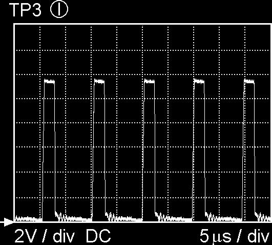


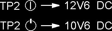


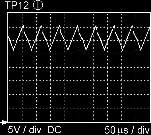

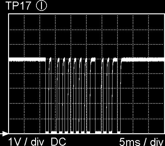

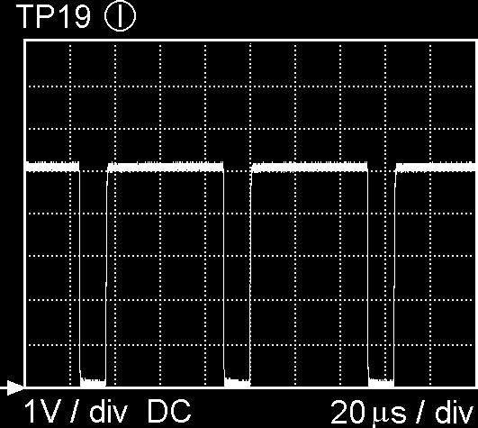


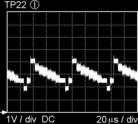
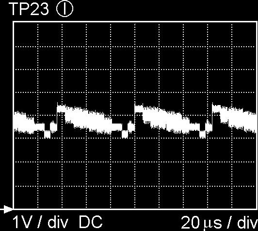
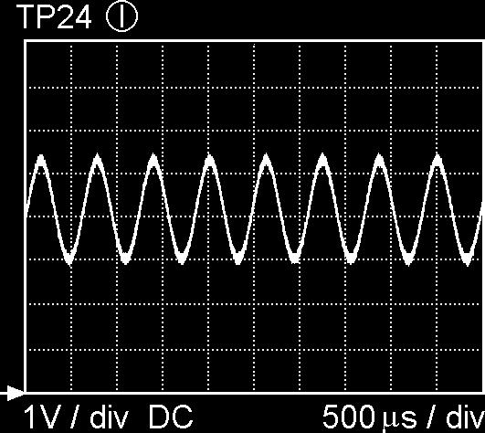

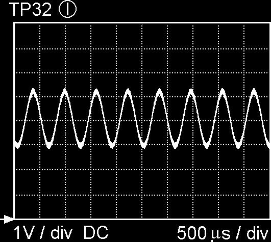

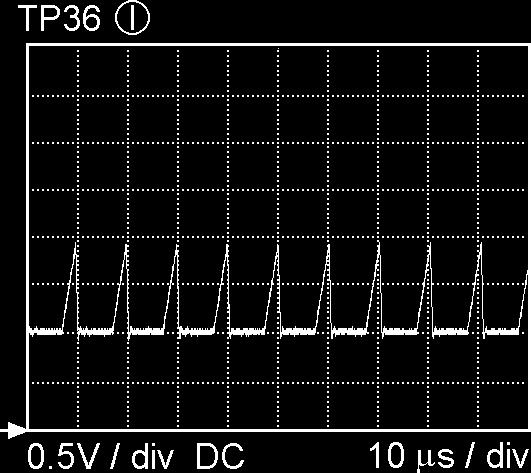


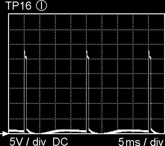
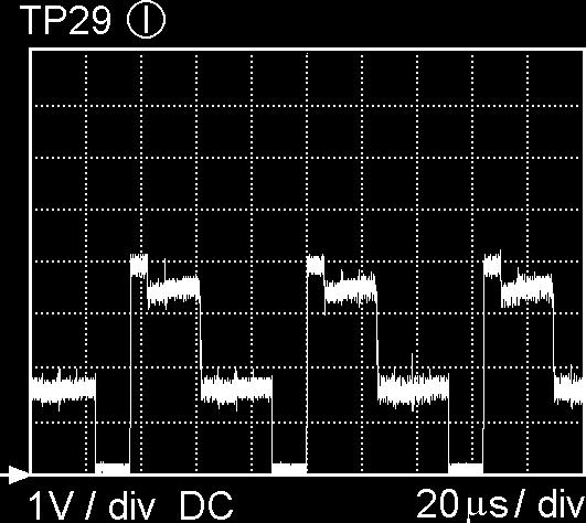
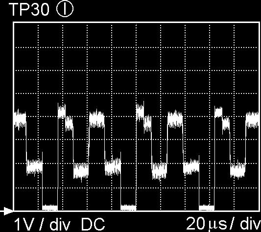
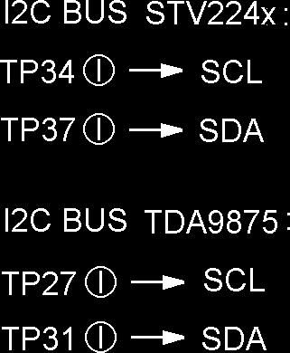


5 4. Oscillograms 5

6 5.- PRINT BOARD LAYOUT 6
7 6.- Electric Diagram 1015 D G F B H D D D D H H E E C D C C E E I F F F F C C B B B B K J J J M J H H I F L L K J D D I F D C D E E E E E E G I I G D D B B B B C C C K H K K L F K K L K K K K L E F H E D E D E F D D F H F C C E B G C K L L D A G M E G E E D A M M M A B B M M M M M B M A E3 7
8 6.- Electric Diagram 2204 C E D D F G H I I I H K H I H M M L L L K K L L M J K L K A A B B B B D E C C C D D E E D E E D D L M E E G I H H I I H H I I H I I I I I I H G H G G H M M L L M L K K J K K K H K L D D M L L J M L A C F D F H L M L H K A B B C C C D E E G G G M L B E D E E C G H I I K6 8
9 6.- Electric Diagram 1001 B B B D C C D D K K K L G G K G K H H K L F F E E F F F B D C C C C D D D D K L G H I I I F E E E D C F E E D E C F C E B B C B D E D E C G B C B E E D D D D D J K B D L J H H H L G B F2 9


10 6.- Electric Diagram 1500 C I H D F E F F H E F D D E F F G G E G I H H I K J K I I G E J L B K F E C D F G F E D D G G F C C G G J K K I J J I D H J H H K G F F F F F G F I H H J J J I K J J E G J J I K B E E D I J K C C1 10
11 6.- Electric Diagram 1679 G F E D C D D K K L B F I H G G F F F F E B B C C C C C E F C C C D E F G F D L K K J J J K L J J J I K E E E E F I F J J G J G I I I I J K F I D D K B B J E C J C H C E E I I D B B L I L L L M L B8 11
12 STV2246: STV2248: Figure 7.1 TV Processor block diagram
13 7.- CIRCUIT DESCRIPTION 7.1 SMALL SIGNAL PROCESSING (Diagram A) The small signal is processed by IC 7015 (STV2246 for Pal sets, STV2248 for Pal/Secam sets), including IF detection, video processing, chroma decoder, RGB, sync processor and sound decoder. The ICs STV2246 and STV2248 are fully controlled by I2C bus and their block diagram can see in fig IF detection IF detection can be intercarrier (no multistandard sets), that means sound and picture are detected in the same circuit (PIF), or QSS (Quasi Split Sound, used in multistandard sets) where sound is detected in a separated circuit (SIF). - PIF input (pins 6, 7): The IF signal coming from pin 11 of the tuner (diagram C) is filtered by the IF SAW filter (1015) and applied to PIF input of IC7015 (pins 6 and 7). The IF bandpass characteristic is determined by the SAW (Surface Acoustic Wave) filter. - PIF oscillator (pins 9, 15, 16): The PIF PLL (phase locked loop) is based on a LC resonator (L5040). Carrier frequency should be adjusted by I2C bus at 38.9 MHz (see chap. 8.3). A filter for the PLL is present at pin 9 (2028, 2029, 3028). AFC is internally controlled for the µc (7600 diagram E) by I2C. Identification signal is also internal. - AGC (pins 5, 8): The IF AGC time constant is fixed by the capacitor 2025 (pin 5). The AGC delayed voltage (pin 8) is applied to pin 1 of the tuner and adjusted by I2C (see chap. 8.4). - Video output (pin 13) : This baseband CVBS signal with 2Vpp of nominal amplitude, contains the FM intercarrier sound signal. Sound is filtered out by a ceramic trap (1032 or 1033) which frequency can be different depending on the system: 5.5 MHz for BG, 6.0 MHz for I or 6,5 MHz for DK. Multistandard sets - The IC STV2248 is used in multistandard sets. - Only picture IF is processed in PIF circuit (pins 6,7), and carrier frequency has a second adjustment (by I2C) at 33.9MHz for L standard (see chap. 8.3). The IC changes automatically between negative (BGIDK) and positive (LL ) modulation. - Sound IF is processed in SIF circuit (QSS system) - SIF input (pins 1, 2): Sound is filtered from IF signal in a SAW filter K9650 (1137). The IF input is present at pin 1 of 1137 and pin 2 is used as a switching input: - If Vpin2 = 0V a 40.40MHz sound carrier is filtered (for L system, L/L signal is high, T7127 conducts). - If Vpin2 = Vpin1 a 33.40MHz sound carrier is filtered (for L,I,BG systems, L/L signal is low, T7127 is cut, D6115 conducts). - SIF AGC (pin 3): The sound IF AGC time constant is fixed by the capacitor C Sound processor - FM demodulation: For intercarrier sets (no multistandard) FM sound is filtered internally from CVBS (pin 13) and demodulated. De-emphasis is also made internally. If the set is Pal/Secam BG or DK, STV2248 is used instead of STV2246. SIF input and AM demodulator are avoided and pins 1, 2 are AC grounded by C Scart audio out (pin 11): The signal at this pin is drived to the euroconnector sound outputs (see Diagram C). - External audio in (pin 14): External audio proceeding of pins 2,6 of euroconnector is applied to this pin. Selection between internal or external is done by an internal switching controlled by I2C (see INT/EXT, chapter 7.6). - Audio out (pin 55): After a volume control (by I2C), this output is drived to the input IN+ of the final sound amplifier IC7187 (Diagram C). Multistandard sets: FM demodulation: This function is done in the same internal circuit of STV2248 that no multi sets, but the input proceeds of SIF circuit, instead of CVBS signal. AM demodulation: In Multistandard sets, also AM demodulation for LL systems is necessary. AM sound is extracted directly from the SIF inputs by an internal circuit. AM/FM switch : This internal switch is commanded by the µc depending on the system selected on the tuning menu Video processing - Video switches (pins 18, 20, 44): The internal CVBS signal is now fed to pin 18 IC7015. External CVBS proceeding from pin 20 of Euroconnector is present on pin 20 of The IC switches between internal and external by I2C bus (see INT/EXT, chapter 7.6). At pin 44 there is an output of CVBS used for the TXT decoder. 12
14 - Luminance processor: CVBS coming from video switches is internally applied to luminance processor, which is composed of chrominance trap filter, luminance delay line and peaking circuits. Sharpness control modifies peaking by I2C. - Black stretch circuit (pin 21): This feature of the picture is fixed (not adjustable). Black stretch capacitor 2250 is connected to pin Chroma Decoding - ACC and chroma filter: Video signal coming from video switches, goes through an internal variable-gain amplifier to the chroma band pass filter. Gain of amplifier is determined by burst amplitude (ACC). If the amplitude of chroma signal is higher than standard, an additional overload circuit decreases it (ACCO). - XTAL (pin 40): The VCO uses one 4,43MHz crystal connected to pin40. PAL sets: STV2246 is used. Bandpass filter and demodulator are fully integrated. Demodulator consist of synchronous detectors. PLL is locked during the burst gate time window. - CLPF (pin 41): The voltage on this chroma PLL filter controls the VCO in order to have the right frequency and phase according burst signal. PAL/ SECAM sets: STV2248 is used. Pal or Secam signals are recognized automatically by the IC. Pal decoding is the same as in STV2246. Secam demodulation is based on a PLL with automatic calibration loop. - Secam bell filter (pin 38): Central frequency of bell filter (4.286 MHz) is fine tuning during frame blanking, using the XTAL frequency (4.433 MHz) as a reference. Tuning control voltage is stored in C Chroma DL: The outputs of the demodulator are applied to an internal chroma delay line. Line number n is delayed 64useg and added to n+1 obtaining U and V signals (R-Y and B-Y) RGB processor - External RGB inputs (pins 25, 26, 27): RGB inputs coming from scart (see diagram C), are AC coupled (C2291/92/93) and converted internally in YUV signals (RGB TO YUV). Then are switched with internal YUV (YUV SWITCH) by fast blanking. - Fast blanking external (pin 28): When fast blanking is high external RGB is displayed, only if TV is in external AV (program 0). Fast blanking can switch signals for full screen (by a DC voltage) or for a part of the screen (by a pulse voltage). - Matrix: After switching, YUV signals are converted to RGB in the internal MATRIX circuit. Saturation control is received from the µc by I2C bus. - APR (pin 24): The APR circuit (Automatic RGB Peak Regulation) compensates the spread of contrast between sources. If one of RGB signals exceeds the APR threshold, 2440 is charged and the gain is decreased. APR threshold can be adjusted in Service menu. - RGB OSD (pins 36, 35, 34): RGB inputs for OSD and TXT coming from µc (7600 diagram E), are AC coupled (C2242/ 43/44) and applied to a RGB SWITCH controlled for the µc by fast blanking input (pin 37). Video controls: Contrast, brightness and saturation are adjusted by I2C for the µc. - BCL input (pin 46): Beam current is limited by circuit BCL/SAF. When beam current is high, voltage of C2460 is lower (Diagram B), D6462 conducts and Vpin46 is lower. When Vpin46 < 5.75V first contrast and then brightness are reduced. - Safety input (pin 46): BCL/SAF circuit has also a safety function. If frame deflection is broken down, T7431 conducts (Diagram B), Vpin46 = 0V and line deflexion (pin 48) is disabled. - RGB output circuit (pins 32, 31, 30): RGB outputs are drived to RGB amplifier (Diagram B). - Digital cut-off loop (pin 33): Cut-off loop permits to control automatically the cut-off point of the 3 RGB cathodes by DC level. At the end of the frame blanking 3 consecutive cut-off lines, B, G and R are created. Cut-off current flows across T7204, T7209 and T7212 (Diagram B) respectively and it is measured on pin 33. When VG2 voltage is adjusted, DC level of RGB outputs is adapted to keep cut-of current. - Warm-up detection circuit (pin 33): At the start up picture is blanked and 3 white lines are drived, instead of cut-off lines. As soon as the start beam current is detected on pin 33, RGB circuit starts in normal operation. If RGB circuit is damaged or grid 2 is low, the RGB circuit could not start (black picture) due to current is not detected Horizontal synchro - Start up (pins 45, 53): The horizontal oscillator starts running when supply voltage of pin 45 reaches 6V and supply voltage of pin 53 reaches 4V. During start up circuit provides a softer operating horizontal output with a 75% of duty cycle. 13
15 Note: The set do not start up if protection voltages are activated (Vpin 49 > 2.5V or Vpin46 < 1V) - Hor. sync. separator: Fully integrated sync. separator with a low pass filter, slicing level at 50% of the synchronized pulse amplitude. - Horizontal 1st loop circuit (pin 50): The first phase locked loop (PLL1) locks the internal line frequency reference on the CVBS input signal. It is composed of an internal VCO (12MHz) that requires the chroma reference frequency (4.43MHz at pin 40), a divider by 768, a line decoder and a phase comparator. Scanning PLL1 filter (SLPF) needs external components on pin 50. PLL1 time constant is automatically controlled by software for broadcasting signals. For video signals (AV and program 99) constant is always fast to prevent top bending on the screen. - LBF (pin 49): Line Fly Back input, is obtained by the network R3456/55 (Diagram B), T7372 and R3371. Output of T7372 is used also as HSYNC of the µc (pin 36 IC7600 diagram D). When the DC voltage of pin 49 is higher than 2.5V, HOUT (pin 48) is inhibited (protection). - SSC output (pin 49): Super Sand Castle output is used only internally. Levels of sandcastle pulse are 5V for burst detection, 3V for line blanking and 2V for frame blanking. - Horizontal 2nd loop circuit: The flyback position respect line blanking on TRC cathode is controlled in this circuit. Phase can be adjusted by I2C. - HOUT (pin 48): Horizontal output is an open collector which one drives the horizontal driver stage (T7440 diagram B) Vertical synchro - Vert. sync. separator: It is an internal integrator to separate frame sync. pulses from CVBS. - Vertical oscillator: Vertical frequency is obtained internally from line frequency by a line counter. Mode used is automatic 50/60Hz identification with 50Hz priority. - Vert. output stage (pin 43): This pulse output is used to drive the sawtooth generator in the vertical amplifier (pin 3 IC7400 diagram B) and also as VSYNC of the µc (pin 37 IC7600 diagram D). The VERT pulse period is 314 lines in 50Hz free running mode (264 in 60Hz) and lines in 50Hz synchronized mode (262.5 in 60Hz). Frame blanking is from line 2 to Vert. amplitude (pin 42): This DC output is applied by a divider resistor (R3416, R3414 diagram B) to pin 4 of IC7400 to control vertical amplitude. It can be adjusted by I2C from 1.5V (max. vert. amplitude) to 6V (min. vert. amplitude). 7.2 RGB AMPLIFIERS (diagram B) - RGB inputs : The inputs of RGB amplifiers come from pins 32, 31 and 30 of IC7015 (Diagram A). White D is adjusted in IC7015 changing the AC level of the inputs by I2C bus and cut-off changing the DC level. - RGB amplifiers (7205, 7210, 7213): RGB circuit consist of 3 inverter amplifiers (7205, 7210, 7213) including active load (7201, 7208, 7211). To improve high frequency amplification there are small capacitors (2204, 2217 and 2230), and to adapt DC level for inputs there is a diode (6225). - Cut off control (7204, 7209, 7212): Cathode current produced at cut-off pulses, is applied to cut-off control circuit, pin 33 of IC7015 (see 5.1.5), across transistors (7204, 7209, 7212). Diode 6243 is added to prevent high voltage in IC Flash-over protections: Clamping diodes to +200V (6201, 6218, 6227) and 1K5 series resistors (3203, 3216, 3326, 3228, 3229) are added for protect the circuit from TRC flash-over. 7.3 DEFLECTION (Diagram B) Frame deflection This function is performed by the integrated circuit TDA1771 (7401). - Frame supply (pins 2, 9, 10): Pin 9 is used to supply the IC except output stage which one is supplied by pin 2. At pin 2 there is a higher voltage during flyback time. This is produced adding the flyback signal present at pin 10 to a +25V supply by D6401 and C Vertical driver (pin 3): A vertical pulse is drived by pin 47 of IC7015. This pulse is used to synchronize vertical oscillator. - Vertical oscillator (pin 6): Saw tooth is performed in the capacitor R3417 makes a feed back to stabilize vertical amplitude from beam current. - Vertical amplitude (pin 4): A DC voltage originated at pin 42 of IC7015 and adjusted I2C bus is applied to pin 4 to modify vertical amplitude. - Vertical output (pin 1): Vertical output is applied to deflection coil. DC current is suppressed by C2404. A voltage proportional to current deflection is present in R3411/12 and a feedback of it is sent to pin 8 across C2405, R3405 and R3407. A DC feedback is obtained by resistor divider R3403 and R3404. Linearity is corrected by the network C2405 and R CRT protection (7430, 7431): When frame deflection is broken down, transistor 7430 is cut, and 7431 conducts so that the signal BCI/SAF=0V and the line is switched off protecting the tube ( see pin 46 of IC7015 ). 14
16 7.3.2 Line deflection The final line transistor is driven by the transformer 5441, whose primary winding is driven by the transistor T7440 connected to the line drive output of IC7015 (pin 48). The horizontal deflection stage is carried out in a conventional way, with the deflection transistor (T7445) and line transformer (5445). Beam current info (BCI) is present at C2460. There are the following supply voltages obtained from line transformer (5545): +25V : To supply frame deflection.. FF : The heather voltage is reduced by R3235/38 and 5201/02 (Diagram B) to obtain 6.3Veff at the CRT. 7.4 SOUND AMPLIFIER (Diagram C) Sound amplifier is a Bridge Tied Load (BTL) amplifier short circuit protection, mute and stand by mode. IC used can be TDA8941 for 14" and 17" models or TDA8943 for 20" and 21" models. TDA8944 is reserved for stereo models (not explained in this manual). - Supply (Vcc, SVR): Main supply (Vcc) is taken from +11V of Power Supply (C2540 diagram D). The IC creates internally a half supply, present in SVR pin and decoupled by 10uF capacitor. - Sound input (IN+): This amplifier has a differential input (IN+,IN-). Audio input is connected to IN+ decoupled by 220nF capacitor (C2186) and IN- is decoupled to ground by other 220nF capacitor. To avoid oscillations there is a 1n5 capacitor connected between both inputs. - Mode input: This input is commanded by the µc and has three modes depending of the voltage level: - Standby mode (Vmode=Vcc): Consumption is very low (used during stand by) - Mute mode (2.5V<Vmode<Vcc): No sound output (used when the set is switched on/off, there is no signal, etc.) - Operating mode: (Vmode<0.5V): Sound output present (normal operation). - Sound output (OUT+/OUT-): Amplified sound is drived to the loudspeakers. Headphones output has been connected in such a way that when headphones are connected, loudspeakers are switched off. 7.5 POWER SUPPLY (Diagram D) Mains isolated switched mode power supply (SMPS), controlled by IC7514 (TDA4605) in variable frequency mode. - Switching behaviour: The switching period is divided in on-time, when energy is extracted from the mains into the primary winding (8-12 of 5525), off-time, when energy in the transformer is supplied to the loads via secondary windings of 5525 and dead-time when no energy is extracted or supplied. - Standby mode: Output voltages are present when the set is on stand by, due to standby is done cutting line deflection. On-time is lower and power consumption is very low Primary side - Degaussing: R3501 is a dual PTC (2 PTC s in one housing). After switch on set, PTC is cold so low-ohmic and so degaussing current is very high. After degaussing, PTC is heated so high-ohmic, so in normal operation degaussing current is very low. - Rectifier: Mains voltage is filtered by L5500, full wave rectified by diodes D6502-D6505 and smoothed by C2505 (300V DC for 220V AC mains) Control circuit (IC7514) - Start up and supply (pin 6): When the set is switched on, a current via R3507 is applied to pin 6. When C2514 is charged to 15V, the power supply starts and a current from pin 5 to T7525 is drived. T7525 and starts conduction and a voltage across transformer windings is built up. The voltage across winding 4-2 is rectified by diode D6521 and used to supply the IC on pin 6. - Soft start (pin 7): The capacitor C2523 causes a slow increase of the duration of the output pulse during start up. - IC output (pin 5): This output drives T7525. R3523 is a fuse resistor to protect IC from short circuits in T7525. D6516 limits the maximum voltage in T Start conduction of T7525 (pin 8): A voltage proceeding from winding 4-2 is applied to this pin. The zero crossing detector recognizes the complete discharge of the energy stored in the transformer core, in addition to a dead time depending on C2508. This circuit guarantee that T7525 starts conduction at minimum Vds voltage (see fig 7.5). - Primary current info (pin 2): Current primary winding is simulated by a pin 2 voltage. - Output voltage info (pin 1): The voltage across winding 4-2 is rectified by diode D6515, divided by R3517, R3518 and R3508 and applied to pin 1. Internal control voltage (Vcont) inversely proportional to Vpin1 is generated. 15
17 - Output regulation (pins 1, 2, 8): IC7514 stabilizes output voltage by controlling T-on and so the frequency and the duty cycle. Start pulse to T7525 is determined by pin 8 circuit (see fig 7.5). Then a sawtooth voltage V2 is generated at pin 2. Stop pulse to T7525 is produced when V2 reaches Vcont. Output control is done by the following way: If output is higher, V1 is higher, Vcont is lower, T-on and output will be reduced. If output is lower, output will be increased. Output voltage of supply can be adjusted by R3518. Mains voltage variation is stabilized in the following way: If mains voltage is higher, slope in the sawtooth voltage V2 is higher, stop point is reached before and T-on is reduced. If mains voltage is lower, T-on is increased Protections - Overload protection (pin 2): This is produced if T-on is increased till V2 voltage reaches the foldback point (see fig 7.5). The IC will switch into overload mode (off and on continuously). - Output voltage protections (pin 6): Limiting values of V6 voltage (7.25V and 16V) provide under and overvoltage protections for the circuit. - Mains overvoltage (pin 3): The voltage at pin 3 IC7515 is a measure for the mains voltage and so the DC voltage across C2505. As soon as the voltage V3 reaches 6.6V, the supply will stop running Secondary side - Line supply: Line supply present at capacitor C2530 should be adjusted to the correct value (depending on the TRC) by means of P3518. This supply is also used to obtain +33V varicap voltage by D6602 (see diagram E). - Sound supply (+11V): This supply is used for sound output amplifier and to feed following stabilizers. - +8V stabilizer: A reference voltage obtained by a resistor divider R3503 and R3505 is amplified in T7501 and T7502 transistors till diode D6572 conducts stabilizing +8V output. When the set switch to stand by, standby voltage is 0V, then T7501 is cut, and +8V is reduced to 0V. - +5V stabilizer: +5V for small signal is made by and D6573 T7577 circuit. R3577 is connected to +8V to switch off +5V when the set is in stand by mode. - +5V stand by: +5STB is regulated by T7575 and D6570. A positive power on reset signal (POR) is obtained in the collector of T7571, which one is cut during start up till R3576 has 0.6V. Figure 7.5 Power supply signals 16
18 7.6 MICROCONTROLLER/TEXT (Diagram E) The CTS-AA chassis is designed to accept 2 different microcontrollers: SAA5531 for TXT models and SAA5541 for no TXT. Both microcontrollers are mounted in the same position (7600), and the associated circuitry is the same. The ROM of the ICs contain an specific program that assures all the functions of the appliance, including 2 menus, one to control the set (see Instructions Manual) and another for Service Mode (see Service Instruct. chapter 8.1). The µc for TXT sets contains a teletext decoder, including the following functions: TXT on/off, reveal, freeze, temporary cancellation, clock, subcode, zoom, index, flof, page +/-, X/26 and 8/30 packet decoding (station identification and startup page). Following there is an explanation of the different functions of the microcontroller indicating pins number assigned: - Tuning (pins 1, 9): The unit has a VST (Voltage Synthesized Tuning) system. This system works by tuning to a station on the tuner through a linear variation of the tuning voltage (V-VARI) from 0V to 33V applied on pin 2 of the tuner. It is generated on pin 1 of the µc and converted to an adequate level for the tuner using T7605. While searching, µc are always reading AFC (Automatic Frequency Control) and video identification signals from IC7015 by I2C bus. When video signal is identified, µc stops searching and do a fine tuning to reach a right AFC value. - Factory facility (pin5): This pin used only in the factory should be connected to +5V by R Service (pin 7): This pin is used to put the set in Service Mode (see chapter 8.1). - INT/EXT input (pin 8): The set can switch to external (AV on the screen) by remote control (selecting program 0) or by rise edge at pin 8 of euroconnector (see diagram C). The µc switches video and audio (see 5.1.2) to external via I2C bus. In both cases the user can switch to internal changing the channel. - Control key (pin 10): Pin 10 is activated by a DC voltage. When control keys are not activated, a voltage of 3V3 is produced by divider R3618 and R3619. If a control key is activated, a resistor (R3665, R3667) are connected in parallel with R3619, decreasing the voltage of pin 10. There are 3 voltage levels depending on value of parallel resistor: 1.85V (910R + 470R), 1V (470R) or 0V (ground circuit). - Band switching (pin 14, 15, 16): There are 3 outputs for band switching pin 15 for VHFI, pin 16 for VHFIII and pin 14 for UHF. The µc controls the channel band in the tuner by a voltage of +5V at the correspondent output. - L/L out-put (pin 18): This signal are only used on multistandard units for switching the system in sound filter (see 5.1.5). L/L output is high for L system. - LED (pin 19): The LED (D6663) lights up with a low current when the television set is ON and with a high current when the set is on Standby. While the set is receiving a remote control signal, the led is blinking. - Signal I2C bus (pins 20,21): This is a communication bus between the µc and the signal IC (7015). Picture and sound controls: User controls (brightness, contrast, colour, sharpness and volume) are processed by the µc and sent to IC7015 by I2C bus. The µc also sends a sound mute when the signal received is interrupted (including channel search) and a video mute during a change of program. - Video input (pin 23): CVBS TXT input are only used on TXT sets. The teletext information is extracted from the video signal inserted on pins Standby (pin 30): When this output is low, the set is switched to stand by. Signal voltages of power supply (+5V, +8V diagram D) are reduced and the line oscillator stops, so there is no signal in pin 48 of IC7015 (diagram A). - Power supply (pins 31, 39, 44): The IC has several +3V3 power supplies, analog (pin 31), core (pin 39), and POR periphery ( pin 44 ). All supplies are present during stand by. - OSD outputs( pins 32, 33, 34, 35): The RGB and fast blanking outputs used for On-Screen Display (OSD) and also for TXT are applied to RGB inputs of IC7015 (pins 34, 35, 36, 37 diagram A). - OSD synchronization (pins 36, 37): In order to synchronize the OSD and the TXT information with the picture signal, the VERT FLYBACK signal (pin 37) and HOR FLYBACK signal (pin 36) are added in inverted form to the integrated circuit. Due to this if the video signal is lost, the TXT keeps synchronism. - Oscillator (pins 41, 42): A 12-MHz oscillator is determined by a 12-MHz crystal (1679) between pins 41 and P.O.R. (pin 43): Power on reset (POR) is activated when the set is switched on. If the µc shows abnormal behaviour it is advisable to reset it switching off/on the set. Reset can be produced also connecting pin 43 to +5V for an instant. - RC5 (pin 45): The commands transmitted by the remote control handset are received by infrared receiver (1685) and passed to the microcontroller for decoding. - Mute output (pin 46): This pin is a 3 state output used to control the sound amplifier (see chapter 7.4): -Stand by mode (Vpin46=0V): T7657 and T7659 are cut, mute signal is 11V -Mute mode (pin46=open): T7659 conducts (by resistor divider), T7657 are cut, mute is 5,5V. -Operating mode (Vpin46=3V3): Both transistors conduct, mute signal is 0V. - EEPROM (pins 49 and 50): The microcontroller is connected to non-volatile memory IC7685 (EEPROM) via bus I2C. The following information are stored in the memory: - Channel data including tuning voltage and band of all the channels. - Personal preferences (PP), menu mix and child lock on user menu. - All settings included on Service Menu. 17
 is fully controlled by I2C for the µc IC7600, so that the most of adjustments of the set can be made by service menu.")
19 8.- ELECTRICAL ADJUSTMENTS 8.1 Service mode The signal processor IC7015 (STV2246 or STV2248) is fully controlled by I2C for the µc IC7600, so that the most of adjustments of the set can be made by service menu. - Enter in Service mode: There are 2 ways to enter in Service mode - By a short circuit between pin 7 of microcontroller ( IC7600 ) and ground while the set is starting up. In this case all controls (volume, contrast, brightness and saturation) are pre-adjusted to the mid position. - When the set is in program 75, by pressing at the same time OSD key (+) on RC and MENU key on local key board during 4 seconds. Service mode is indicated by a S symbol on the down left corner of the screen. - Display Service Menu : When the set is in service mode it is possible to display Service Menu by OSD key (+) on RC. Using P+, P- keys of remote control the different items can be displayed (see table 8.1): Table 8.1. Service menu. Settings are hexadecimal values - Pre setting values: When E2PROM is replaced, pre-setting values indicated on table 8.1 are stored by the µc. (see 8.7 E2PROM). - Adjust by Service Mode: When a item is selected, using V+, V- keys of remote control it can be adjusted. Items 5, 16 and 17 have fixed values = pre setting values, rest of items see 8.2 to Remove service menu: There are 2 ways to remove service menu - Saving the new settings: Using OSD (+), MENU or INSTALL keys on RC. - Keeping the old settings: Switching the TV to stand by. Service mode continues active. - Remove Service Mode: Switching off the TV (be careful to disconnect pin 7 of microcontroller of ground) 8.2 Power supply and focusing: - Power supply voltage: - Adjust brightness and contrast controls at minimum. - Connect a DC voltmeter across C2530 (Diagram D). - Adjust R3518 for a required voltage depending on the model and the TRC used ( see table 11, page 23). - Focusing: - Adjust with the potentiometer placed on the line output transformer. 18
20 8.3 AFC IF Carrier frequency can be adjusted in automatic or manual way. It is recommended the automatic way. There is an adjusting symbol for AFC on the top of the service menu consisting of a double arrow (><). If only one arrow appears (<) or (>) AFC should be readjusted to reach double arrow (><) Automatic AFC adjustment - Insert a 38.9MHz 106dB/µV signal in pin11 of the tuner (1001 diagram C) across the following network: Note: For Pal I sets, frequency is 38.9MHz only if saw filter (1015 diagram A) used is J1952. If saw filter is J1951 frequency of the inserted signal should be 39.5MHz. - Select AFC Adjust (item 23 of Service menu) and press V+ on RC. - Press OSD key to save adjustment. - Enter in Service menu again and check that adjusting symbol is correct (><). If not, readjust AFC Fine (item 2 of Service menu) till symbol is (><). Multistandard sets A second adjustment for L system is necessary when the set is multistandard, to do it TV should be tuned in the first half of BI (L channel). - Repeat the same automatic AFC adjustment procedure, inserting a signal of 33.9MHz instead of 38.9MHz and using AFC LP Adj. (item 24 of Service menu) and AFC Fine LP (item 4 of Service menu) Manual AFC adjustment: - Insert the frequency signal defined in Adjust the value of AFC coarse (item 1 of Service menu) to 00 and the item value of AFC fine (item of Service menu) to Increase the AFC coarse value just till adjusting symbol is (><) or (<) and adjust AFC Fine to fine a value just in the middle of the range fulfilling the correct symbol (><). Multistandard sets TV should be tuned in the first half of BI (L channel) - Repeat the AFC Manual AFC adjustment procedure inserting a signal of 33.9MHz instead of 38.9MHz and using AFC coarse LP (item 3 of Service menu) and AFC fine LP (item 4 of Service menu). 8.4 AGC Adjustment - Connect a pattern generator to the aerial input with RF signal amplitude = 1mV. - Adjust the value of AGC start (item 6 of Service menu) so that voltage at pin 1 of the Tuner (1001) is 3.7V. 8.5 White D Manual cut-off: Item 8 of adjusting values should be 00 (see table 8.1), that means set is in automatic cut-off. However it is possible that RGB do not start (black picture), due to grid 2 is not adjusted. In this case we recommend to change to Manual cut-off ( Item 8 = 01), pre-adjust grid 2 to have a good picture and change to automatic cut-off ( Item 8 = 0) before continue adjusting (see warm-up detection circuit in 7.1.5) Grid 2: - Connect a white pattern generator. - Adjust contrast at 07 and brightness at Adjust VG2 potentiometer ( in line transformer ) till voltage in collector of transistor 7213 is 142V in 20"/21" or 134V in 14" (measured with a DC voltmeter). 19

21 8.5.3 White checking: - Connect pattern generator containing grey scale - Adjust the set to normal operation and reduce the saturation control to minimum. - Allow the set to warm up about 10 minutes and check visually if the grey scale has correct colour. - If not, enter to Service menu and adjust G and B gain (items 14 and 15) until a desired grey is obtained. In the case that adjusting is difficult, start again with the setting values of table 8.1 (items 9, 10, 13, 14, 15). 8.6 Geometry - Connect a circle pattern generator with the controls at nominal conditions and enter to service menu. - Horizontal shift: Adjust to have picture centred in horizontal position by service menu item Vertical amplitude: Adjust picture height to cover the screen by service menu item Vertical centring: Occasionally it is possible to correct the vertical centring cutting resistors R3400 or R TXT Shift: Horizontal shift of OSD or TXT can be adjusted by item 20 of service menu. 8.7 Options: The type of chassis is defined by items 21 and 22 of service menu. The following alternatives are available: Important note: All the chassis have identification sheet when the chassis type is indicated: «Cod. service: SXXMXX», where SXX means the option of system and MXX means the option of menu Example: S03M00 means system = 03 (Pal-Secam B/G-DK) and menu = 00 (13 Languages menu) When the chassis or the EEPROM (IC7685) have to be replaced, be careful to keep the same type of chassis, setting correctly the chassis options. 8.8 Error messages The microcomputer also detects errors in circuits connected to the I 2 C (Inter IC) bus. These error messages are communicated via OSD (On Screen Display) : 20
22 9. Safety instructions, maintenance instructions, warning and notes Safety Instructions for Repairs 1. Safety regulations require that during a repair: - The set should be connected to the mains via an isolating transformer. - Safety components, indicated by the symbol! should be replaced by components identical to the original ones - When replacing the CRT, safety goggles must be worn. 2. Safety regulations require also that after a repair: - The set should be returned in its original condition. - The cabinet should be checked for defects to avoid touching, by the customer, of inner parts. - The insulation of the mains lead should be checked for external damage. - The mains lead strain relief should be checked onits function - The cableform and EHT cable are routed correctly and fixed with the mounted cable clamps in order to avoid touching of the CRT, hot components or heat sinks - The electrical resistance between mains plug and the secondary side is checked. This check can be done as follows: Unplug the mains cord and connect a wire tween the two pins of the mains plug. Switch on the TV with the main switch. Measure the resistance value between the pins of the mains plug and the metal shielding of the tuner or the aerial connection on the set. The reading should be between 4.5 M and 12 M. Switch off the TV and remove the wire between the two pins of the mains plug. Thermally loaded solder joints should be oldered. -This includes components like LOT, the line utput transistor, flyback capacitor. Maintenance Instructions It is recommended to have a maintenance inspection carried out periodically by a qualified service employee. The interval depends on the usage conditions. - When the set is used in a living room the recommended interval is 3 to 5 years. When the set is used in the kitchen or garage this interval is 1 year. - During the maintenance inspection the above mentioned "safety instructions for repair" should be caried out. The power supply and deflection circuitry on the chassis, the CRT panel and the neck of the CRT should be cleaned. Warnings 1.In order to prevent damage to IC's and transistors any flash-over of the EHT should be avoided. To prevent damage to the picture tube the method, indicated in Fig. 9, has to be applied to discharge the picture tube. Make use of an EHT probe and a universal meter is 0V (after approx 30s). 2. ESD. All IC's and many other semi-conductors are sensitive to electrostatic discharges (ESD). Careless handing during repair can reduce life drastically. When repairing, make sure that you are connected with the same potential as the mass of the set via wrist wrap with resistance. Keep components and tools on the same potential. 3. Proceed with care when testing the EHT section and the picture tube. 4. Never replace any modules or any other parts while the set is switched on. 5. Use plastic instead of metal alignment tools. This will prevent any short circuits and the danger of a circuit becoming unstable. 6. Upon a repair of a transistor or an IC assembly (e.g. a transistor or IC with heatsink and spring) remounting should be carried out in the following order: 1. Mount transistor or IC on heatsink with spring. 2. Resolder the joints. Notes 1. After replacing the microcomputer first solder the shielding before testing the set. This is needed as the shielding is used for earth connection. If this is not done the set can switch into protection mode (see description of the SMPS). 2. Do not use heatsink as earth reference. 3. The direct voltages and waveforms should be measured relative to the nearest earthing point on the printed circuit board. 4. Voltages and oscillograms in the power supply section have been measured for both normal operation ( ) and in the stand-by mode ( ). As an input signal a colour bar pattern has been used. 5. The picture tube PWB has printed spark gaps. Each spark gap is connected between and electrode of the picture tube and the Aguadog coating. FIG. 9 21
23 10. List of abbreviations µc Microcomputer µp INT/EXT Switching signal from µc to TS7876 and TS7877 (diagram C) making together with pin 8 of SCART connector the INT/EXT switching signal; "low" for internal, "high" for external AF Alternating Current AFC Automatic Frecuency Control AGC Automatic Gain Control AM Amplitude modulation APR Automatic Peak Regulation AQUA Aquadag on the CRT panel for spark gaps and used for making BCI signal AV Audio and Video cinches on the rear side of the set BCI Beam Current Info; if beam current increases the BCI signal decrases. BCI is used for contrast reduction if beam current is too high BCI' Derived from BCI; if beam current increases (more white), EHT decreases so picture will become too big. BCI and so BCI' decreases for increasing beam current (diagram C) and the picture will be corrected. BG/I Switching signal from µc; "low" for I or DK reception (6.0 or 6.5 MHZ FM sound), "high" for BG reception (5.5 MHZ FM sound) BG/I/DK/LL' Sond system BG/I/DK/LL' indicate frecuency distance between sound and picture carriers (5.5 MHz for I, 6.5 MHz for DK and LL') BG/L Switching signal from µc; "low" for BGIDK reception (negative modulation, FM sound), "high" for LL' reception (positive modulation, AM sound) BRI Brightness control signal (same as BRIGHTNESS) BRIGHTNESS Control signal (from µc, but on DC level via RC network) for brightness control of the video controller IC7015/6D BSW1 Bandswitcing signal from µc to 2 to 3 decorer IC 7002 BSW2 Bandswitching signal from µc to 2 to 3 decorer IC7002 CONTRAST Control signal (from µc, but on DC level via RC network) for brightness control of the video controller IC7015/6D CRT Picture tube CVS Colour Video Blanking Synchronisation from pin 7 IF detector IC7015/6A DC Direct current EEPROM Electrical Eresable Programmable Read Only Memory EHT Extra High Tension (25 KV) FET Field Effect Transistor FF Filatement (heather voltage) FM Frecuency MOdulation HOR FLYBACK Horizontal flyback pulse (15625 Hz) used for locking the horizontal oscillator in IC7015/6E and for locking the OSD generator in the µc HOR Horizontal drive signal from IC7015/6E to line output stage HUE Tint ajustment for NTSC system I 2 C Digital Control bus of the microcomputer IDENT Status signal; "low" for horizontal synchronisation, "high" in case horizantal synchronisation is detected IF Intermediate Frecuency int/ext Switching signal derived fromµµp INT/EXT and pin 8 of SCART to pin 16 IC7015/6B and IC7140 (diagram D); "low" for internal, "high" for external L/L' Switching signal from µc; "low" for BGIDKL (picture at 38.9 MHz) reception, "high" for L' reception (picture at 33.4 MHz) LED Light Emitting Diode LOT Line Output Transformer MUTE PROG 0 Only for sets whithout SCART + AV ; "low" for program 0 muting the sound, "high" for program 1-39 NIL Non InterLace NTSC National Television System Committee OSD On Screen Display OSD FAST BLANKING Fast blanking info from OSD generator in µc to video controller IC7015/6D for blanking the RGB info to enable OSD-G insertion OSD-G Green info from OSD generator in µc to video controller IC7015 for inserting green OSD info on screen. PAL Phase Alternating Lines PLL Phase Locked Loop POR Power On Reset (ensures the µc starts up it's software only if the power supply of the µc itself is high enough) POS/NEG Switching signal from IC7140 via BG/L; "high" for positive modulation (LL'), highihmic for negative modulation (BGIDK). PP Personal Preference PROT Prottection signal from frame IC7400; in case vertical flyback generator in IC7400 is not activted, the voltage at pin 8 IC7400 becomes 2V. Protection circuit in IC7400 will make pin 7 "high" overrulling the HOR FLYBACK and SANDCASTLE. The constant "high" sandcastle is supplied to the luminance circuit and so the picture will be blanked. PTC Positive Temperature Coefficient Resistor RC5 Remote Control 5 system RGB Red Green Blue ROM Random Access Memory SATURATION Control signal (from µc, but on DC level via RC network) for saturation control of the video controller IC7015/6D SAW Surface Acoustic Wave; very precise bandpass filter. SC Sandcastle signal from IC7015/6F to delay line IC7271 and SECAM chroma decoder IC7250 SCART CVBS IN CVBS signal from pin 2 SCART to external input pin 15 IC7015/6B SCART CVBS OUT CVBS signal from IF detector IC 7015/6A to pin 19 SCART SCART AUDIO IN Audio signal from SCART + AV cinches to source select IC7140 SCART AUDIO OUT Audio signal from IC 7140 to pin 1 and 3 SCART + AV SCART Euroconnector SCL Clock line of the I²C-bus SDA Data line of the I²C-bus SDM Service Default Mode; predefined mode for faultfinding (see chapter 8) SECAM SEquential Couleur A Memoire SMPS Switched Mode Power Suplly STANDBY Switching signal; "low" for standby (only line is shut), "high" for normal operation SYNC Synchronisation TP-1 Tets point 1 UHF Ultra High Frecuency band from tuning range V-IN The DC voltage across C2505 present at pin 11 of the primary side of the transformer V-VARI Tuning voltage (0-30V) VERT FEEDBLACK 50Hz vertical flyback pulse used for locking the vertical oscillator in IC7015/6E VERT FLYBACK 50Hz vertical flyback pulse from frame IC7400 lo lock the OSD generator in µc VERT DRIVE Vertical drive signal from IC7415/6E to frame amplifier IC7400 Vg2 Voltage on Grid 2 of the picture tube VHF Very High Frecuency band from tuning range VOLUME Control signal (from µc, but on DC level via RC network) for volume control of sound processing in IC7015/6F VST Voltage Synthesized Tuning Y Luminance part of video signal 22


24 11. REPLACEMENT PARTS LIST CTS-AA CHASIS Electrical 11.2 Electromechanical CTS-AA CHASIS TABLE 11: 23
25 11.3 Mechanical, chasis and switches CTS-AA CHASIS POSITION * SCREEN * TV MODEL * COLOUR NG-BLACK BL-WHITE GR-GREY MA-IVORY GO-DARK GREY VE-GREEN RS-PINK RJ-RED AZ-BLUE PL-SILVER HOW TO ORDER EXAMPLE: FRONT CABINET OF TV700TX COLOUR BLUE: A * 14 * TV700TX * AZ 24
PHILIPS Anubis A(AC) Chassis
 Chassis") PHILIPS Anubis A(AC) Chassis Recommended Safety Parts Item Part No. Description 4822 276 12597 MAIN SWITCH 4822 258 30274 FUSE HOLDER 4822 255 40955 LED HOLDER 4822 267 60243 EURO CONN. 4822 265 30389
PHILIPS Anubis A(AC) Chassis Recommended Safety Parts Item Part No. Description 4822 276 12597 MAIN SWITCH 4822 258 30274 FUSE HOLDER 4822 255 40955 LED HOLDER 4822 267 60243 EURO CONN. 4822 265 30389
SERVICE MANUAL MATSUI 1410R/1410T/2010R. TV Version 1.1. This Manual is available in Electronic format.
 SERVICE MANUAL MATSUI 40R/40T/200R TV Version. This Manual is available in Electronic format. Mastercare, Maylands Avenue, Hemel Hempstead, Hertfordshire, HP2 7TG, Telephone 0442 88804 MATSUI 40R/40T/200R
Synchronization circuit with synchronized vertical divider system for 60 Hz TDA2579C
 FEATURES Synchronization and horizontal part Horizontal sync separator and noise inverter Horizontal oscillator Horizontal output stage Horizontal phase detector (sync to oscillator) Triple current source
11AK30 / MONO - SERVICE MENU
 11AK30 / MONO - SERVICE MENU PREPARED FOR: FROM http://monitor.net.ru ALICIA ENTERING TO SERVICE MENU: In order to enter service menu, first enter the main menu and then press the digits 4, 7, 2 and 5
INTEGRATED CIRCUITS DATA SHEET. TDA4510 PAL decoder. Product specification File under Integrated Circuits, IC02
 INTEGRATED CIRCUITS DATA SHEET File under Integrated Circuits, IC02 March 1986 GENERAL DESCRIPTION The is a colour decoder for the PAL standard, which is pin sequent compatible with multistandard decoder
Elements of a Television System
 1 Elements of a Television System 1 Elements of a Television System The fundamental aim of a television system is to extend the sense of sight beyond its natural limits, along with the sound associated
CP-830FP Chassis TX-29E50D TX-29E50D/B TX-29PS12D TX-29PS12F TX-29PS12P SPECIFICATIONS. Order No: PCZ C2
 Order No: PCZ0510103C2 SPECIFICATIONS Power Source: Power Consumption: 220-240V a.c.,50hz 100W Stand-by Power Consumption: 1,5W Aerial Impedance: 75Ω unbalanced, Coaxial Type Receiving System: PAL-I, B/G,
TV2K - TXT SERVICE MANUAL COLOUR TELEVISION RECEIVER SECIFICATION
 TV2K - TXT COLOUR TELEVISION RECEIVER SERVICE MANUAL SECIFICATION SYSTEM PAL/SECAM,B/G,I. POWER INPUT AC 170-245V(50/60Hz) POWER CONSUMPTION 60W AERIAL IMPEDANCE 75OHM UNVALANCED TUNER VOLTAGE SYNTHESIZER
Index. Aspect ratio 14,246 Attenuator, aerial Automatic chrominance control (a.c.c.) 112,113,130 Automatic phase control (a.p.c.
 112,113,130 Automatic phase control (a.p.c.") Index Al electrodes 211 Additive mixing 3 Aerial, acceptance angle 251, 252 amplifier 260 attenuator 260-1 bandwidth 254 cable 257-8 dipole 250-4 directivity 250 front-to-back ratio 254 gron 254,255,256
Index Al electrodes 211 Additive mixing 3 Aerial, acceptance angle 251, 252 amplifier 260 attenuator 260-1 bandwidth 254 cable 257-8 dipole 250-4 directivity 250 front-to-back ratio 254 gron 254,255,256
Presented by: Amany Mohamed Yara Naguib May Mohamed Sara Mahmoud Maha Ali. Supervised by: Dr.Mohamed Abd El Ghany
 Presented by: Amany Mohamed Yara Naguib May Mohamed Sara Mahmoud Maha Ali Supervised by: Dr.Mohamed Abd El Ghany Analogue Terrestrial TV. No satellite Transmission Digital Satellite TV. Uses satellite
Brief Description of Circuit Functions. The brief ckt. description of V20 107E5 17 Monitor
 Exhibit 4 Brief Description of Circuit Functions The brief ckt. description of V20 107E5 17 Monitor 0. Functional Block Diagram 1. General Description 2. Description of Circuit Diagram A. Power Supply
DATA SHEET. TDA8433 Deflection processor for computer controlled TV receivers INTEGRATED CIRCUITS
 INTEGRATED CIRCUITS DATA SHEET File under Integrated Circuits, IC02 August 1991 FEATURES I 2 C-bus interface Input for vertical sync Sawtooth generator with amplitude independent of frequency ertical deflection
BLOCK DIAGRAM. Brightness Control -120V. Vertical Blanking, FBT 30V 15V. Protection TDA8172 ( IC601) Circuit -12V 12V. H/V Sync Processor
 Circuit -12V 12V. H/V Sync Processor") BLOCK DIAGRAM H.V DY CDT H- Conver gence Dynamic Focus Static Focus Auto Beam Limit Heater ( ) Screen G1 < OSD > H / V POSITION H / V SIZE SPCC TRAPIZODE PIN BALANCE PARALLELOGRAM CORNERTRAP DDC ON/OFF
BLOCK DIAGRAM H.V DY CDT H- Conver gence Dynamic Focus Static Focus Auto Beam Limit Heater ( ) Screen G1 < OSD > H / V POSITION H / V SIZE SPCC TRAPIZODE PIN BALANCE PARALLELOGRAM CORNERTRAP DDC ON/OFF
ALIGNMENT INSTRUCTION (5N11)
") CHASSIS ADJUSTMENT 1. EEPROM partial initializing 1-1 Go to the function set menu (there are two ways;) ALIGNMENT INSTRUCTION (5N11) a. Press VOL+ key and VOL- key on the control board at the same time
CHASSIS ADJUSTMENT 1. EEPROM partial initializing 1-1 Go to the function set menu (there are two ways;) ALIGNMENT INSTRUCTION (5N11) a. Press VOL+ key and VOL- key on the control board at the same time
ELECTRICAL ADJUSTMENT INSTRUCTIONS
 ELECTRICAL ADJUSTMENT INSTRUCTIONS General Note: "CBA" is abbreviation for "Circuit Board Assembly." NOTE: Electrical adjustments are required after replacing circuit components and certain mechanical
BTV Tuesday 21 November 2006
 Test Review Test from last Thursday. Biggest sellers of converters are HD to composite. All of these monitors in the studio are composite.. Identify the only portion of the vertical blanking interval waveform
4. Alignment and Adjustments
 4. Alignment and Adjustments 4-1 Preadjustment 4-1-1 Factory Mode 1. Do not attempt these adjustments in the Video Mode. 2. The Factory Mode adjustments are necessary when either the EEPROM (IC02) or the
Television Principles and Practice
 Television Principles and Practice J. S. Zarach Senior Lecturer. North Staffordshire Polytechnic Noel M. Morris Principal Lecturer. North Staffordshire Polytechnic M J. S. Zarach and Noel M. Morris 1979
CATHODE RAY OSCILLOSCOPE. Basic block diagrams Principle of operation Measurement of voltage, current and frequency
 CATHODE RAY OSCILLOSCOPE Basic block diagrams Principle of operation Measurement of voltage, current and frequency 103 INTRODUCTION: The cathode-ray oscilloscope (CRO) is a multipurpose display instrument
INTEGRATED CIRCUITS DATA SHEET. TDA8304 Small signal combination IC for colour TV. Preliminary specification File under Integrated Circuits, IC02
 INTEGRATED CIRCUITS DATA SHEET Small signal combination IC for colour TV File under Integrated Circuits, IC02 September 1991 FEATURES Gain controlled vision IF amplifier Synchronous demodulator for negative
Recommended Safety Parts Cont d.
 Matrix Item See Model Book X-Ray Precautions(See Notes)... Grundig G1000 Chassis 4 Service Notes (See Notes).... Grundig G1000 Chassis 4 AF Amplifier... Grundig CUC 7851 5 IF Amplifier... Grundig CUC 7861
SDA 3302 Family. GHz PLL with I 2 C Bus and Four Chip Addresses
 GHz PLL with I 2 C Bus and Four Chip Addresses Preliminary Data Features 1-chip system for MPU control (I 2 C bus) 4 programmable chip addresses Short pull-in time for quick channel switch-over and optimized
SingMai Electronics SM06. Advanced Composite Video Interface: HD-SDI to acvi converter module. User Manual. Revision 0.
 SM06 Advanced Composite Video Interface: HD-SDI to acvi converter module User Manual Revision 0.4 1 st May 2017 Page 1 of 26 Revision History Date Revisions Version 17-07-2016 First Draft. 0.1 28-08-2016
DATA SHEET. TDA8360; TDA8361; TDA8362 Integrated PAL and PAL/NTSC TV processors. Philips Semiconductors INTEGRATED CIRCUITS.
 INTEGRATED CIRCUITS DATA SHEET File under Integrated Circuits, IC02 March 1994 Philips Semiconductors FEATURES Available in TDA8360, TDA8361 and TDA8362 Vision IF amplifier with high sensitivity and good
LX600 LCD TV Technical Information
 LX600 LCD TV Technical Information TC-32LX600 Outline Features Overall Block Diagram A Board Main Layout Power On Sequence Protection Shutdown Troubleshooting Adjustments 1 Features Model TC-LX60 TC-LX600
V25 V25+ WS WS WS WS V27 WS-65517
 2005 Down to1 HIGH SPEED TROUBLESHOOTING V25-V27 CHASSIS V25 V25+ WS-48515 WS-55615 WS-55515 WS-65615 WS-65515 WS-73615 V25++ WS-55815 WS-65815 WS-55517 V27 WS-65517 WS-73517 MITSUBISHI DIGITAL ELECTRONICS
DEPARTMENT OF THE ARMY TECHNICAL BULLETIN CALIBRATION PROCEDURE FOR AUTOMATIC VIDEO CORRECTOR TEKTRONIX, MODEL 1440 (NSN )
") DEPARTMENT OF THE ARMY TECHNICAL BULLETIN TB 11-5820-861-35 CALIBRATION PROCEDURE FOR AUTOMATIC VIDEO CORRECTOR TEKTRONIX, MODEL 1440 (NSN 5820-00-570-1978) Headquarters, Department of the Army, Washington,
DEPARTMENT OF THE ARMY TECHNICAL BULLETIN TB 11-5820-861-35 CALIBRATION PROCEDURE FOR AUTOMATIC VIDEO CORRECTOR TEKTRONIX, MODEL 1440 (NSN 5820-00-570-1978) Headquarters, Department of the Army, Washington,
Model 5240 Digital to Analog Key Converter Data Pack
 Model 5240 Digital to Analog Key Converter Data Pack E NSEMBLE D E S I G N S Revision 2.1 SW v2.0 This data pack provides detailed installation, configuration and operation information for the 5240 Digital
MODIFYING A SMALL 12V OPEN FRAME INDUSTRIAL VIDEO MONITOR TO BECOME A 525/625 & 405 LINE MULTI - STANDARD MAINS POWERED UNIT. H. Holden. (Dec.
 MODIFYING A SMALL 12V OPEN FRAME INDUSTRIAL VIDEO MONITOR TO BECOME A 525/625 & 405 LINE MULTI - STANDARD MAINS POWERED UNIT. H. Holden. (Dec. 2017) INTRODUCTION: Small open frame video monitors were made
Representative Block Diagram. Outputs. Sound Trap/Luma Filter/Luma Delay/ Chroma Filter/PAL and NTSC Decoder/Hue and Saturation Control
 Order this document by MC44/D The Motorola MC44, a member of the MC44 Chroma 4 family, is designed to provide RGB or YUV outputs from a variety of inputs. The inputs can be composite video (two inputs),
Learning to Use The VG91 Universal Video Generator
 Learning to Use The VG91 Universal Video Generator Todays TV-video systems can be divided into 3 sections: 1) Tuner/IF, 2) Video and 3) Audio. The VG91 provides signals to fully test and isolate defects
MULTIDYNE INNOVATIONS IN TELEVISION TESTING & DISTRIBUTION DIGITAL VIDEO, AUDIO & DATA FIBER OPTIC MULTIPLEXER TRANSPORT SYSTEM
 MULTIDYNE INNOVATIONS IN TELEVISION TESTING & DISTRIBUTION INSTRUCTION MANUAL DVM-1000 DIGITAL VIDEO, AUDIO & DATA FIBER OPTIC MULTIPLEXER TRANSPORT SYSTEM MULTIDYNE Electronics, Inc. Innovations in Television
16 Stage Bi-Directional LED Sequencer
 16 Stage Bi-Directional LED Sequencer The bi-directional sequencer uses a 4 bit binary up/down counter (CD4516) and two "1 of 8 line decoders" (74HC138 or 74HCT138) to generate the popular "Night Rider"
TV PATTERN GENERATOR GV-298
 TV PATTERN GENERATOR GV-298 1 GENERAL 1.1 Description The exceptional attributes the GV-298 video generator consists of have been designed in accordance with the latest trends of modern technology. Its
4. Alignment and Adjustments
 Alignment and Adjustments 4. Alignment and Adjustments 4-1 Preadjustment 4-1-1 Factory Mode 1. Do not attempt these adjustments in the Video Mode. 2. The Factory Mode adjustments are necessary when either
NTE1416 Integrated Circuit Chrominance and Luminance Processor for NTSC Color TV
 NTE1416 Integrated Circuit Chrominance and Luminance Processor for NTSC Color TV Description: The NTE1416 is an MSI integrated circuit in a 28 Lead DIP type package designed for NTSC systems to process
Circuit Description. Introduction. Index of this chapter:
 Page 1 of 35 Circuit Description Index of this chapter: 1. Introduction 2. Audio Signal Processing 3. Video Signal Processing 4. Synchronization 5. Deflection 6. Power Supply 7. Control 8. Abbreviations
COMTECH TECHNOLOGY CO., LTD. MTAS-F SPECIFICATION
 1.Feature DVB-T demodulator for COFDM with excellent multipath performance, meeting: * DVB-T Digital Television Standard ETS 300744 * Nordig-Unified v1.0.3 Receiver Specification * DTG performance requirements
COMPOSITE VIDEO LUMINANCE METER MODEL VLM-40 LUMINANCE MODEL VLM-40 NTSC TECHNICAL INSTRUCTION MANUAL
 COMPOSITE VIDEO METER MODEL VLM- COMPOSITE VIDEO METER MODEL VLM- NTSC TECHNICAL INSTRUCTION MANUAL VLM- NTSC TECHNICAL INSTRUCTION MANUAL INTRODUCTION EASY-TO-USE VIDEO LEVEL METER... SIMULTANEOUS DISPLAY...
INTEGRATED CIRCUITS DATA SHEET. TDA8501 PAL/NTSC encoder. Preliminary specification File under Integrated Circuits, IC02
 INTEGRATED CIRCUITS DATA SHEET File under Integrated Circuits, IC02 April 1993 FEATURES Two input stages: R, G, B and (R Y), (B Y), Y with multiplexing Chrominance processing, highly integrated, includes
MASTR II BASE STATION 12/24V POWER SUPPLY 19A149979P1-120 VOLT/60 Hz 19A149979P2-230 VOLT/50 Hz
 Mobile Communications MASTR II BASE STATION 12/24V POWER SUPPLY 19A149979P1-120 VOLT/60 Hz 19A149979P2-230 VOLT/50 Hz CAUTION THESE SERVICING INSTRUCTIONS ARE FOR USE BY QUALI- FIED PERSONNEL ONLY. TO
Dan Schuster Arusha Technical College March 4, 2010
 Television Theory Of Operation Dan Schuster Arusha Technical College March 4, 2010 My TV Background 34 years in Automation and Image Electronics MS in Electrical and Computer Engineering Designed Television
Service Manual for D9100 Series Digital-Control Color Monitor
 Service Manual for D9100 Series Digital-Control Color Monitor Wells-Gardner Electronics 9500 W. 55 th Street Suite A McCook, Illinois 60525-3605 (708) 290-2100 069X3015-100 Revision: B / E01025 Date: 8-24-00
NAPIER. University School of Engineering. Advanced Communication Systems Module: SE Television Broadcast Signal.
 NAPIER. University School of Engineering Television Broadcast Signal. luminance colour channel channel distance sound signal By Klaus Jørgensen Napier No. 04007824 Teacher Ian Mackenzie Abstract Klaus
4. Alignment and Adjustments (Electrical)
") 4. Alignment and Adjustments (Electrical) 4- Preadjustment 4-- Factory Mode. Do not attempt these adjustments in the Video Mode. 2. The Factory Mode adjustments are necessary when either the EEPROM (IC92)
4. Alignment and Adjustments (Electrical) 4- Preadjustment 4-- Factory Mode. Do not attempt these adjustments in the Video Mode. 2. The Factory Mode adjustments are necessary when either the EEPROM (IC92)
SPECIFICATION. DVB-T/ DVB-C / Worldwide hybrid Switchable NIM Tuner
 1.Feature *. Integrated RF switch, NTSC VIF demodulator, COFDM demodulator *. All-in-one full NIM function with compact size, optimal solution for cost reduction and shortening product development lead-time.
5. Service Modes, Error Codes, and Fault Finding
 Service Modes, Error Codes, and Fault Finding LC4.2E AA 5. EN 11 5. Service Modes, Error Codes, and Fault Finding Index of this chapter: 1. Test Points 2. Service Modes 3. Problems and Solving Tips (related
Circuit Description. Introduction. Página Web 1 de 39. Index of this chapter:
 Página Web 1 de 39 Circuit Description Index of this chapter: 1. Introduction 2. Audio Signal Processing 3. Video Signal Processing 4. Synchronization 5. Deflection 6. Power Supply 7. Control 8. Abbreviations
Video Signals and Circuits Part 2
 Video Signals and Circuits Part 2 Bill Sheets K2MQJ Rudy Graf KA2CWL In the first part of this article the basic signal structure of a TV signal was discussed, and how a color video signal is structured.
AN5636K. SECAM/PAL signal conversion IC. ICs for TV. Overview. Features. Applications
 SECAM/PAL signal conversion IC Overview The is an IC which converts the SECAM signal into the quasi-pal signal. This IC can add the SECAM signal processing function while rationalizing the external parts
FD Trinitron Colour Television
 R 4-205-569-32(1) FD Trinitron Television Instruction Manual GB KV-14LM1U 2000 by Sony Corporation NOTICE FOR CUSTOMERS IN THE UNITED KINGDOM A moulded plug complying with BS1363 is fitted to this equipment
Introduction. Table of Contents
 Introduction Thank you for purchasing this television set. This handbook has been designed to help you install and operate your TV set. We would strongly recommend that you read it thoroughly. We hope
SECTION 4 CIRCUIT ADJUSTMENTS
 SECTION 4 CIRCUIT ADJUSTMENTS 4-1. ELECTRICAL ADJUSTMENTS Service adjustments to this model can be performed using the supplied Remote Commander RM-883. i + (ON SCREEN DISPLAY) HOW TO ENTER INTO SERVICE
2. Alignment and Adjustments
 Alignment and ments 2. Alignment and ments 2- General Alignment Instructions. Usually, a color TV-VCR needs only slight touch-up adjustment upon installation. Check the basic characteristics such as height,
SingMai Electronics SM06. Advanced Composite Video Interface: DVI/HD-SDI to acvi converter module. User Manual. Revision th December 2016
 SM06 Advanced Composite Video Interface: DVI/HD-SDI to acvi converter module User Manual Revision 0.3 30 th December 2016 Page 1 of 23 Revision History Date Revisions Version 17-07-2016 First Draft. 0.1
 I R T Electronics Pty Ltd A.B.N. 35 000 832 575 26 Hotham Parade, ARTARMON N.S.W. 2064 AUSTRALIA National: Phone: (02) 9439 3744 Fax: (02) 9439 7439 International: +61 2 9439 3744 +61 2 9439 7439 Email:
FOCUS VOLTAGE ADJUSTMENT 1. Receive RETMA pattern signal. 2. Adjust the FOCUS VOLUME on the FBT and make the picture on the screen be finest.
 General Information Also Covers: DVT-1484D, DVT-2084D Ferguson FG 14 CB 12V, FG 20 CB 12V Goodmans TVC 1400 & TVC 14 VP Electrical Adjustments (TV) GENERAL INFORMATION All adjustments are throughly checked
Service Service Service. B8 Series Chasssis Manual Contents 5. Service Modes, Error Codes and Faultfinding 6. Block Diagrams and Testpoints
 Color Television Service Service Service Chassis B8 Series Chasssis Manual 7562 Contents 5. Service Modes, Error Codes and Faultfinding 6. Block Diagrams and Testpoints 7. Electrical Diagrams and PWB's
Goodmans Helpline Phone Number
 Goodmans Helpline Phone Number 0870 873 0080 contents Introduction 4 Connecting up 5 Overview diagrams 6 Getting started 8 Using the main menu 10 Troubleshooting 15 Technical Specifications 16 3 introduction
3B SCIENTIFIC PHYSICS
 B SCIENTIFIC PHYSICS Triode S 11 Instruction sheet 1/15 ALF 1 5 7 1 Guide pin Connection pins Cathode plate Heater filament 5 Grid Anode 7 -mm plug for connecting anode 1. Safety instructions Hot cathode
Stereo Box Pre Box Amp Box Amp Box Mono Switch Box. Tuner Box Dock Box F / V Phono Box MM Record Box USB Phono Box II
 Overview Box Program Stereo Box Pre Box Amp Box Amp Box Mono Switch Box Tuner Box Dock Box F / V Phono Box MM Record Box USB Phono Box II Phono Box II USB Phono Box SE II Tube Box II Tube Box SE II Head
2002 DP-2X Chassis Projection Television Information INSTRUCTOR Alvie Rodgers C.E.T. (Chamblee, GA.)
") Dec 00 (ver g) Training Materials Prepared by: ALVIE RODGERS C.E.T. 00 and 00 MODEL RELEASE DIGITAL HD READY PTV Chassis Model # Aspect DP-7 5SWX0B 6X9 57SWX0B 65SWX0B DP-7D DP-6 DP- DP-G 57TWX0B 6X9 65TWX0B
Dec 00 (ver g) Training Materials Prepared by: ALVIE RODGERS C.E.T. 00 and 00 MODEL RELEASE DIGITAL HD READY PTV Chassis Model # Aspect DP-7 5SWX0B 6X9 57SWX0B 65SWX0B DP-7D DP-6 DP- DP-G 57TWX0B 6X9 65TWX0B
NewScope-7A Operating Manual
 2016 SIMMCONN Labs, LLC All rights reserved NewScope-7A Operating Manual Preliminary May 13, 2017 NewScope-7A Operating Manual 1 Introduction... 3 1.1 Kit compatibility... 3 2 Initial Inspection... 3 3
XS 2000 HT User Manual
 XS 2000 HT User Manual INDEX Before the installation pag. 3 Introduction to the use pag. 4 1 Remote control functions pag. 5 2 Input panel and keys pag. 6 3 Connections inputs pag. 7 - Possibilities of
MODEL OTM-4870 FREQUENCY AGILE 870MHz F.C.C. COMPATIBLE TELEVISION MODULATOR
 MODEL OTM-4870 FREQUENCY AGILE 870MHz F.C.C. COMPATIBLE TELEVISION MODULATOR USERS MANUAL Phone: (209) 586-1022 (800) 545-1022 Fax: (209) 586-1026 E-Mail: salessupport@olsontech.com 025-000412 Rev. B www.olsontech.com
PAL-SECAM LUMA-CHROMA & DEFLECTION PROCESSOR ICAT. Vcc BIN COR RIN BRIG FBL CLPF CXTL CKP F425 ACC CDR F440 SAT CDB GND CKS DLO
 PAL-SECAM LUMA-CHROMA & DEFLECTION PROCESSOR PRELIMINARY DATA RGB AND FAST BLANKING INPUTS AUTOMATIC CUT-OFF CONTROL DC-CONTROLLED BRIGHTNESS, CON- TRAST AND SATURATION CERAMIC 500kHz VCO FOR LINE DEFLEC-
Model 5405 Dual Analog Sync Generator Data Pack
 Model 5405 Dual Analog Sync Generator Data Pack E NSEMBLE D E S I G N S Revision 2.1 SW v2.0 This data pack provides detailed installation, configuration and operation information for the 5405 Dual Analog
A MISSILE INSTRUMENTATION ENCODER
 A MISSILE INSTRUMENTATION ENCODER Item Type text; Proceedings Authors CONN, RAYMOND; BREEDLOVE, PHILLIP Publisher International Foundation for Telemetering Journal International Telemetering Conference
. The vertical pull-in range is approximately 10 Hz at fv = 60 Hz.
 Ordering number: EN2781B Monolithic Linear IC CRT Display Synchronization Deflection Circuit Overview The is a sync-deflection circuit IC dedicated to CRT display use. It can be connected to the LA7832/7833,
Q1. a) Attempt any THREE of the following: 12M
 Attempt any THREE of the following: 12M") Important Instructions to examiners: 1) The answers should be examined by key words and not as word-to-word as given in the model answer scheme. 2) The model answer and the answer written by candidate
Important Instructions to examiners: 1) The answers should be examined by key words and not as word-to-word as given in the model answer scheme. 2) The model answer and the answer written by candidate
Amateur TV Receiver By Ian F Bennett G6TVJ
 Amateur TV Receiver By Ian F Bennett G6TVJ Here is a design for an ATV receiver which makes use of a Sharp Satellite tuner module. The module was bought from "Satellite Surplus" at a rally a year or so
17 19 PROFESSIONAL LCD COLOUR MONITOR ART
 17 19 PROFESSIONAL LCD COLOUR MONITOR ART. 41657-41659 Via Don Arrigoni, 5 24020 Rovetta S. Lorenzo (Bergamo) http://www.comelit.eu e-mail:export.department@comelit.it WARNING: TO REDUCE THE RISK OF FIRE
Software Analog Video Inputs
 Software FG-38-II has signed drivers for 32-bit and 64-bit Microsoft Windows. The standard interfaces such as Microsoft Video for Windows / WDM and Twain are supported to use third party video software.
COHERENCE ONE PREAMPLIFIER
 COHERENCE ONE PREAMPLIFIER OWNER S MANUAL TABLE OF CONTENTS Introduction Features Unpacking Instructions Installation Phono Cartridge Loading Basic Troubleshooting Technical Specifications Introduction
MULTIDYNE Electronics, Inc. Innovations in Television Testing & distribution
 INSTRUCTION MANUAL DVM-2200 DIGITAL VIDEO, AUDIO & DATA FIBER OPTIC MULTIPLEXER TRANSPORT SYSTEM MULTIDYNE Electronics, Inc. Innovations in Television Testing & distribution 1-(800)-4TV-TEST, 1-(800)-488-8378
LCD TV Technical Training Manual
 LCD TV Technical Training Manual ML-038C Chassis 37,42 inch LCD TV - RZ-37LZ30 (Market:EU) - RZ-42LZ30 (Market:EU) 1/22 Contents 1. Circuit operation Description 1.1 Block diagram 1.2 Signal Input block
PAST EXAM PAPER & MEMO N3 ABOUT THE QUESTION PAPERS:
 EKURHULENI TECH COLLEGE. No. 3 Mogale Square, Krugersdorp. Website: www. ekurhulenitech.co.za Email: info@ekurhulenitech.co.za TEL: 011 040 7343 CELL: 073 770 3028/060 715 4529 PAST EXAM PAPER & MEMO N3
clipping; yellow LED lights when limiting action occurs. Input Section Features
 ELX-1A Rack-Mount Mic/Line Mixer Four inputs, one output in a single rack space Very-highery-high-quality audio performance High reliability Extensive filtering circuitry and shielding protect against
USER MANUAL. Blackburst, Sync, Audio Tone Generator. For Models BSG-50, RM-50/BSG, SR-50/BSG. Doc Rev. F (C) Copyright 2014
 Copyright 2014") HORITA BSG-50 Blackburst, Sync, Audio Tone Generator USER MANUAL For Models BSG-50, RM-50/BSG, SR-50/BSG Doc. 070450 Rev. F (C) Copyright 2014 P.O. Box 3993, Mission Viejo, CA 92690 (949) 489-0240 www.horita.com
HORITA BSG-50 Blackburst, Sync, Audio Tone Generator USER MANUAL For Models BSG-50, RM-50/BSG, SR-50/BSG Doc. 070450 Rev. F (C) Copyright 2014 P.O. Box 3993, Mission Viejo, CA 92690 (949) 489-0240 www.horita.com
PREPARATION FOR SERVICING
 How to Enter the Service Mode PREPARATION FOR SERVICING Caution: 1 1. Optical sensors system are used for Tape Start and End Sensor on this equipment. Read this page carefully and prepare as described
MAX11503 BUFFER. Σ +6dB BUFFER GND *REMOVE AND SHORT FOR DC-COUPLED OPERATION
 19-4031; Rev 0; 2/08 General Description The is a low-power video amplifier with a Y/C summer and chroma mute. The device accepts an S-video or Y/C input and sums the luma (Y) and chroma (C) signals into
SPECIFICATION. Multistandard Demodulator tuner. ATSC/Legacy analog NTSC/BTSC
 1.Feature MATSCA-SF is the Multistandard Demodulator ATSC/QAM/NTSC module which integrates product is especially suitable for PVR or PIP-TV application. - Supported modulation standards:. ATSC digital
WVR500 Waveform/Vector Monitor
 Service Manual WVR500 Waveform/Vector Monitor 070-8897-01 Warning The servicing instructions are for use by qualified personnel only. To avoid personal injury, do not perform any servicing unless you are
SPECIFICATION. DVB-T / Worldwide NIM Tuner
 1.Feature * DVB-T demodulator for COFDM with excellent multipath performance, meeting: * DVB-T Digital Television Standard ETS 300744 * Nordig-Unified v1.0.3 Receiver Specification 2.Applications * Digital
LA7837, Vertical Deflection Circuit with TV/CRT Display Drive. Package Dimensions
 Ordering number:enn3313c Monolithic Linear IC LA7837, 7838 ertical Deflection Circuit with T/CRT Display Drive Overview The LA7837, 7838 are vertical deflection output ICs developed for use in high-grade
Projection Television
 S Training Manual Projection Television Circuit Description and Troubleshooting Course: TVP-08 Course Description and Troubleshooting: RA-4 Chassis Prepared by: National Training Department Sony Service
4.9 BEAM BLANKING AND PULSING OPTIONS
 4.9 BEAM BLANKING AND PULSING OPTIONS Beam Blanker BNC DESCRIPTION OF BLANKER CONTROLS Beam Blanker assembly Electron Gun Controls Blanker BNC: An input BNC on one of the 1⅓ CF flanges on the Flange Multiplexer
Interfaces and Sync Processors
 Interfaces and Sync Processors Kramer Electronics has a full line of video, audio and sync interfaces. The group is divided into two sections Format Interfaces and Video Sync Processors. The Format Interface
National Park Service Photo. Utah 400 Series 1. Digital Routing Switcher.
 National Park Service Photo Utah 400 Series 1 Digital Routing Switcher Utah Scientific has been involved in the design and manufacture of routing switchers for audio and video signals for over thirty years.
CATHODE-RAY OSCILLOSCOPE (CRO)
") CATHODE-RAY OSCILLOSCOPE (CRO) I N T R O D U C T I O N : The cathode-ray oscilloscope (CRO) is a multipurpose display instrument used for the observation, measurement, and analysis of waveforms by plotting
CATHODE-RAY OSCILLOSCOPE (CRO) I N T R O D U C T I O N : The cathode-ray oscilloscope (CRO) is a multipurpose display instrument used for the observation, measurement, and analysis of waveforms by plotting
Data Sheet. Electronic displays
 Data Pack F Issued November 0 029629 Data Sheet Electronic displays Three types of display are available; each has differences as far as the display appearance, operation and electrical characteristics
Instructions when using for the first time 1. Installation (3) 2. Using the Televiewer (4)
 2. Using the Televiewer (4)") Instructions when using for the first time 1. Installation (3) 2. Using the Televiewer (4) 1 Introduction Chapter! This manual is intended for the 'Trust Televiewer 1610 RC'. The device allows you to switch
Instructions when using for the first time 1. Installation (3) 2. Using the Televiewer (4) 1 Introduction Chapter! This manual is intended for the 'Trust Televiewer 1610 RC'. The device allows you to switch
Xpresionn Digital Terrestrial Receiver. User Guide
 Xpresionn 2150 Digital Terrestrial Receiver User Guide GENERAL INFORMATION...3 A) SAFETY PRECAUTIONS...3 B) MAIN FEATURES...4 C) CONTENTS OF THE PACKAGING...4 D) REMOTE CONTROL...5 INSTALLATION...6 A)
Waveform Monitor/Vectorscope, PM 5661 Waveform Monitor/Vectorscope, Sc-H, PM 5661/70
 Waveform Monitor/Vectorscope, PM 5661 Waveform Monitor/Vectorscope, Sc-H, PM 5661/70 Two instruments combined in one unit PM 5661/70 features Sc-H phase display Input Signal Subtraction (A-B) for easy
Specifications. FTS-260 Series
 Specifications DVB-S2 NIM Tuner Date : 2014. 03. 26. Revision F2 #1501, Halla sigma Valley, 442-2 Sangdaewon-dong, Jungwon-gu, Sungnam City, Gyeonggi-do, Korea, 462-807 Tel. 86-755-26508927 Fax. 86-755-26505315-1
1x12 VGA & Audio over CAT5 Splitter
 SP-9112 1x12 VGA & Audio over CAT5 Splitter User Manual rev: 160322 Made in Taiwan Safety and Notice The SP-9112 1x12 VGA & Audio over CAT5 Splitter has been tested for conformance to safety regulations
STX Stairs lighting controller.
 Stairs lighting controller STX-1795 The STX-1795 controller serves for a dynamic control of the lighting of stairs. The lighting is switched on for consecutive steps, upwards or downwards, depending on
TV Synchronism Generation with PIC Microcontroller
 TV Synchronism Generation with PIC Microcontroller With the widespread conversion of the TV transmission and coding standards, from the early analog (NTSC, PAL, SECAM) systems to the modern digital formats
MAX7461 Loss-of-Sync Alarm
 General Description The single-channel loss-of-sync alarm () provides composite video sync detection in NTSC, PAL, and SECAM standard-definition television (SDTV) systems. The s advanced detection circuitry
Multifunction Digital Timer
 Multifunction Digital Timer 72 x72 mm Timer with Easy-to-use Functions Nine output modes accommodate a wide variety of applications. All parameters set by scroll-through menus accessed from the front panel.