PAM4 Signaling for 56G Serial Link Applications A Tutorial Image
|
|
|
- Victor Hicks
- 6 years ago
- Views:
Transcription


1 TITLE PAM4 Signaling for 56G Serial Link Applications A Tutorial Image Hongtao Zhang, Brandon Jiao, Yu Liao, and Geoff Zhang


2 PAM4 Signaling for 56G Serial Link Applications A Tutorial Hongtao Zhang, Brandon Jiao, Yu Liao, and Geoff Zhang

3 SPEAKERS Geoff Zhang, SerDes Technology Group, Xilinx Inc. Geoff Zhang received his Ph.D. in 1997 in microwave engineering and signal processing from Iowa State University, Ames, Iowa. He joined Xilinx Inc. in 2013 as director of architecture and modeling in the SerDes Technology Group. Prior to joining Xilinx he has employment experiences with HiSilicon, Huawei Technologies, LSI, Agere Systems, Lucent Technologies, and Texas Instruments. His current interest is in transceiver architecture modeling and system level end-to-end simulation, both electrical and optical.
4 Outline An overview of current status of 56G standards Early pioneers in PAM4 SerDes over a decade ago From IEEE P802.3bj KP4 to OIF CEI-56G-PAM4 and IEEE P802.3bs A brief review of high speed serial link using NRZ signaling High speed link system composition, signal integrity degradation Nyquist frequency, signal PSD, frequency- and time- domain link analysis Channel ISI and common equalization schemes: TX FIR, RX CTLE, RX DFE Channel impedance mismatches, reflections, and system crosstalk impact A tutorial on PAM4 signaling for high speed serial communications PAM4 basics, coding schemes and level mapping Signal PDF, SNR degradations from NRZ to PAM4 Situations in which PAM4 has advantages over NRZ PAM4 signaling slicer naming definitions and usages Eye diagram anatomy the difficulty for PAM4 signaling Impact from various sources of impairments on PAM4 signaling
5 Outline (Con t) A tutorial on PAM4 signaling for high speed serial links (Con t) Timing recovery: transition densities, 2x oversampled vs. baud-rate CDR Transmitter FIR implementation and TX de-emphasis example Receiver CTLE example in reducing channel ISI and opening up the eye Analog-based RX architecture: CTLE/AGC, analog FFE, FIR-DFE, and IIR-DFE ADC-based RX architecture: CTLE/AGC, analog FFE, ADC, DSP (FFE, DFE, ) Equalizer coefficient adaptations and convergence example On-die eye monitor, sampled eyes, and SER/BER computations 1/(1+D) precoding to reduce DFE induced burst errors FEC to help link system to achieve the desired BER (<1e-15) Channel operating margin (COM) for PAM4 signaling IBIS-AMI modeling and link simulations for PAM4 signaling Test and measurement of PAM4 signaling pattern definitions Glossaries and References

6 56G Standards Overview


7 Early Pioneers in PAM4 SerDes About a dozen years ago there were two PAM4 SerDes designs out there, by Rambus and Accelerant, respectively, targeting 6-10Gbps applications
 35dB at 13GHz with KR4 FEC or 30dB without FEC 100GBASE-KP4: PAM4 for 28Gbps PAM4 (Clause 94) 33dB at 7GHz with KP4 FEC KP4 the earliest PAM4 standard Limited applications")
8 The Two-PHY Solutions 100GBASE-KR4: NRZ for 25.78Gbps NRZ (Clause 93) 35dB at 13GHz with KR4 FEC or 30dB without FEC 100GBASE-KP4: PAM4 for 28Gbps PAM4 (Clause 94) 33dB at 7GHz with KP4 FEC KP4 the earliest PAM4 standard Limited applications adopting it Moving to 56G using PAM4 Starting from IEEE P802.3bj KP4 IEEE P802.3bs and OIF CEI-56G-PAM4 Baseline specs are in a state of flux Both standards leveraged a lot from the KP4 spec


9 CEI-56G-PAM4-VSR/MR/LR Baseline Specs VSR: C2M, < 10cm, one connector up to 10dB; raw BER < 1e-6 VSR MR: C2C for midrange backplanes, < 50cm, one connector up to 21dB; raw BER < 1e-6 LR MR LR: backplanes or copper cables, two connectors up to 31dB; raw BER < 3e-4
 in March 2015 adopted PAM4 for CDAUI-8 interfaces for C2C and C2M RS(544, 514, 15, 10) FEC, the KP4 FEC 8 x 53.")
10 IEEE P802.3bs CDAUI-8 The 400GbE task force (802.3bs) in March 2015 adopted PAM4 for CDAUI-8 interfaces for C2C and C2M RS(544, 514, 15, 10) FEC, the KP4 FEC 8 x Gbps PCS encoding ratio = 257/256 KP4 FEC ratio = 544/514 Thus, 544/514*257/256*50 = Gbps
11 A Brief Review of Serial Link using NRZ
, reflections, crosstalk, etc.")
12 A Typical High Speed Serial Link Data is transmitted from TX to RX through a channel composed of various components The channel length can be as long as 1m for backplane channels and 5m for copper cable channels Signal integrity suffers along the path due to many impairments Jitter, noise, intra-pair skews, frequency-dependent attenuation (ISI), reflections, crosstalk, etc. System margin depends on both passive and active components
 is characterized by the following Two variant voltage levels are used to represent a 0 and a 1 The voltage level remains constant throughout the bit interval Symbol = Bit.")
13 Non-Return to Zero (NRZ) Modulation NRZ (a.k.a. PAM2) is characterized by the following Two variant voltage levels are used to represent a 0 and a 1 The voltage level remains constant throughout the bit interval Symbol = Bit. There is one eye in each UI (unit interval) Example: for serial data at R s = 56Gbps UI (or T b ) = 1/56e9 = ps < 18 ps Nyquist frequency = R s / 2 = 28 GHz Power spectrum density (PSD) follows sinc 2 () function At R s and its integer multiples, PSD is 0
 Delay, attenuation, spreading, ripples, Note that the more accurate transfer function can be derived")
14 Time-Frequency Domain Views and Conversion Frequency domain (Insertion loss) Loss, nulls, smooth/bumpiness, Time domain (Impulse response) Delay, attenuation, spreading, ripples, Note that the more accurate transfer function can be derived as
15 Chanel ISI and Equalization Techniques Inter-Symbol Interference (ISI) depicts the phenomenon in which energy in one bit leaks into neighboring bits, on both sides Two commonly used techniques to mitigate ISI Equalization is the most powerful and efficient Signal modulation is another optional solution


16 3-tap FIR example FIR coefficients typically satisfy C -1 + C 0 + C 1 = 1 C 0 - C -1 - C 1 > 0 TX De-Emphasis via FIR Filtering C -1 =0, C 0 =1, C 1 =0 0dB de-emphasis C -1 =0.075, C 0 =0.75, C 1 = dB de-emphasis

17 RX CTLE Equalization The CTLE filters RX input signal by either boosting high frequency content attenuated in the channel or relatively attenuating low frequency content It introduces zeros to offset the freq-dependent loss CTLE will have the same effect on noise The CTLE is generally preceded/followed by AGC


18 RX DFE for Removing Post-Cursor ISI DFE subtracts out channel impulse responses from the previous data bits so as to zero out post-cursor ISI contributions on the current bit x x x x x DFE tries to remove dominant positive ISI to open up the eye DFE needs to counteract dominant negative ISI to open up the eye
19 Channel Equalization Goals The preliminary goal of channel equalization can be viewed as In f-domain: to flatten the response within the frequency of interest In t-domain: to remove pre- & post- cursor ISI and restrict energy Non-linear equalizers, such as DFE, do not directly fit into the above picture The ultimate goal is to ensure the system works within the BER target
 is used to characterize channel")
20 Reflections Could be More Harmful Than Loss Reflections, due to channel impedance mismatches, could be even more harmful than channel insertion loss in certain link setups Insertion loss deviation (ILD, defined as ILD = IL fitted attenuation) is used to characterize channel smoothness
21 Crosstalk Could be More Harmful Than Loss Crosstalk (noise coupled through vias, connectors, packages, etc.) could be more harmful than channel insertion loss in link setups Several different concepts are used to assess the strength of crosstalk, evolved as data rate increases PSXT: power sum of crosstalk PSNEXT power sum of NEXT PSFEXT power sum of FEXT ICR: insertion loss to crosstalk ratio, defined as IL - PSXT ICN: integrated crosstalk noise COM: channel operating margin

22 A Tutorial on PAM4 for Serial Link

23 PAM4 4-Level Pulse Amplitude Modulation Every 2 bits are mapped to one symbol 2-bits has 4 unique combinations, thus 4 signal levels The mapping can be Linear or Gray Gray coding Only one bit error per symbol is made for incorrect decisions Support dual-mode with PAM2, by grounding the LSB This is the coding adopted in all the PAM4 standards MSB is the bit transmitted first Three common naming conventions for PAM4 signal levels They might be used interchangeably in this presentation /3-1/

24 TX and RX Signaling Process 1
25 Binary to PAM4 and Back to Binary Example
26 PAM4 Power Spectrum Density PAM4 only requires half of the bandwidth of that of NRZ, as can be seen from its PSD (red), in comparison with the PSD for PAM2 (blue) For the same throughput, if NRZ is 56Gbps, then PAM4 is running at 56Gbps or 28Gsym (per second) or 28GBd (per second) The Nyquist frequency for PAM4 is 56/4 = 14GHz The Nyquist frequency for PAM2 is 56/2 = 28GHz

27 Eye Height Comparison between PAM2 & PAM4 Eye height for PAM4 is 1/3 of that of PAM2, thus SNR loss = 20 log ~ 9. 5dB In practice, there is further degradation due to nonlinearity Together one should consider >11 db SNR penalty

28 Eye Width Comparison between PAM2 & PAM4 The illustration is based on raised cosine channel with b = 1 Although the Nyquist frequency is half for PAM4 than for PAM2, in reality the real eye width is only between 1/2UI and 2/3UI, far less than 2x of NRZ eye width The 3 vertical eyes are not symmetrical Because PAM4 has four voltage levels, there are transitions between non-adjacent signal levels, which take longer time than required for transitions between adjacent levels, thereby narrowing the eye
29 More on Eye Height and Eye Width The middle eye (in red) is most symmetrical vertically The top and bottom eyes (in blue) are not vertically symmetrical The largest eye width (EW largest ) doesn t correspond to the largest eye height, where the eye width is EW In this example, EW largest = EW = ~60% UI for the middle eye EW largest is ~60% UI, while EW is ~48% UI for the top and bottom eye Page 29

30 When PAM4 Might be More Advantageous Case 1 D is ~11dB Big suck-out Case 2 D is ~32dB

 56dB is too much for PAM2 D is more than 30dB The suck-out does not affect PAM4")
31 When PAM4 Might be More Advantageous (Con t) 20dB for NRZ is reasonable The D is about 11dB Clearly, the 9.5dB does not directly apply Note: The two eye masks have the same height (in mv) and same width (in ps) 56dB is too much for PAM2 D is more than 30dB The suck-out does not affect PAM4 as much as affect PAM2 Note: eye masks are not listed since the PAM2 is totally closed
 If linearity is assumed DH = 2*ELP (= 2*h 0 ), EHP = 3*ELP (= 3*h 0 ) DL = 2*ELN (= -2*h 0 ), EHN = 3*ELN (= -3*h 0 )")
32 Suggested Latches/Slicers Naming Conventions The following naming conventions are suggested data latches DH, DZ, and DL error latches EHP, ELP, ELN, and EHN crossing latches CH, CZ, and CL If vertical symmetry is assumed DL = -DH, EHN = -EHP, ELN = -ELP (= h 0 ) If linearity is assumed DH = 2*ELP (= 2*h 0 ), EHP = 3*ELP (= 3*h 0 ) DL = 2*ELN (= -2*h 0 ), EHN = 3*ELN (= -3*h 0 ) Nonlinearity effect h 0 To assume EHP =3*h 0 and DH=2*h 0, ELP=h 0, etc. is not always a good practice A good approach is to adapt them separately


33 Eye Diagram Anatomy NRZ only has 8 trace combinations for 3 consecutive bits PAM4 has 64 trace combinations for 3 consecutive symbols There are 6 combinations (40 unique traces) in PAM4 that are NRZ-like The rest are much less well-behaved Even the well-behaved traces form completely closed eyes


34 ISI Impact Example The combined channel has the single bit response with cursors marked A PAM2 and PAM4 coded pattern transmits through the channel No equalization is applied The PAM2 eye is pretty open The PAM4 eye is completely closed


35 Rule of Thumb for Eye Closures With Reasonable TX design and package design, it is estimated that, absent of noise, PAM2 eye starts to close at ~10dB PAM4 eye starts to close at ~4.5dB In time domain, ISI should be controlled to be 1/3 rd for PAM4 than for PAM2 Channel loss profile also matters
 Case 2: There is no skew between MSB and LSB (red) Case 3: MSB is late w.")
36 Clock Skew Impact on TX Output Eye If the PAM4 signaling is formed such that the MSB and LSB are summed up, clock skew could make the eye misaligned horizontally The signal quality will further deteriorate after a channel An example is given for clock skew between MSB and LSB Case 1: MSB is early w.r.t. LSB by 1/8th UI (blue) Case 2: There is no skew between MSB and LSB (red) Case 3: MSB is late w.r.t. LSB by 1/8th UI (green)
 Case 2: MSB and LSB drivers are matched (red) Case 3:")
37 TX Driver Strength Impact on TX Output Eye If the PAM4 signaling is formed such that the MSB and LSB are summed up, driver mismatch could make the eye misaligned vertically The signal quality will further deteriorate after a channel An example is given for different driver rise/fall times Case 1: MSB driver has faster rise/fall times (blue) Case 2: MSB and LSB drivers are matched (red) Case 3: MSB driver has slower rise/fall times (green)


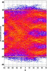
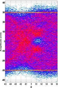
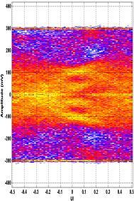
38 Reflection Impact on PAM4 Signal The impact of reflections on PAM4 could be 3x worse in magnitude than on PAM2 The LHS eyes are constructed without considering the reflections circled in red The RHS eyes are simulated with all the reflections PAM4 degrades much faster
39 Crosstalk Impact on PAM4 Signal Crosstalk noise hurts link margin more with the peak-peak value, rather than the RMS value When aggressor number is > 3, the crosstalk noise is approaching bounded Gaussian, with peakpeak/rms up to 11 based on empirical data PAM4 aggressors tend to have slightly smaller RMS, but similar peak-peak as for PAM2 The impact of crosstalk noise on PAM4 signaling is approximately 3x worse than that on PAM2


40 Intra-pair Skew Impact on PAM4 Signal Intra-pair skew can be due to various sources Different routing lengths, connector fan out, fiber weave effect, etc. Intra-pair skew tends to impacts PAM4 much more than PAM2, for the same baud-rate In addition to extra loss, mode conversion also needs to be taken into account An example on mode conversion on next page

41 Mode Conversion Impact Example Link-1 has 0 ps skew, while Link-2 has 15 ps skew between P&N SDC increased by more than 30dB for the skewed pair If simulation had SDC21 ignored, the system performance would be optimistic
 Each active block could add more nonlinearity The larger the signal, the more nonlinearity PAM4 needs more dynamic range DFE assumes linear system to work optimally If")
42 Nonlinearity Impact on PAM4 Signal PAM4 has three vertical eyes, but system margin bottleneck lies with the worst eye Nonlinearity plays a much bigger role in PAM4 than in NRZ Nonlinearity starts right at TX output (see R LM ) Each active block could add more nonlinearity The larger the signal, the more nonlinearity PAM4 needs more dynamic range DFE assumes linear system to work optimally If ADC is used, the full-scale range applies Adopting nonsymmetrical data and error slicers can help, but only to a certain extent (More on nonlinearity later)
43 2x Oversampling Vs. Baud-Rate CDR Compared with the commonly used 2x oversampling Bang-Bang CDR, baud-rate CDR does not guarantee the sampling phase around the center of the symbol Baud rate CDR has less power consumption due to only one phase clock needed vs. two phase clocks for 2x oversampled CDR In-phase clock Quadrature clock In-phase clock
 For PAM2, the average")
44 PAM4 Time Recovery Transition Density Transition Density (TD) is illustrated for linear coding 16 traces between 2 symbols 4 are between the same levels 16-4 = 12 are level transitions Average TD = 75% ( =12/16 ) For PAM2, the average TD is 50%

45 PAM4 Time Recovery Selected Crossings The narrower the distribution, the less the timing jitter The major transition (red) has the tightest distribution and -3-1 depends on timing slicer level placement One can conditionally select transitions for timing recovery This will reduce TD, thus affecting CDR bandwidth
>2*h0 && d(k+1)>0 && d(k+1)<2*h0 if x(k)>2*h0, CDR too early else if x(k)<2*h0, CDR too late endif")
46 2x Oversampled Timing Recovery Example The transitions between level 3 and level 2 has the following logic if d(k)>2*h0 && d(k+1)>0 && d(k+1)<2*h0 if x(k)>2*h0, CDR too early else if x(k)<2*h0, CDR too late endif endif

47 MMSE Baud-Rate CDR MMSE timing recovery optimizes the sampling phase by minimizing the expected value of the squared error Practical high-speed adaptation algorithms often use only 1-bit representations of the sign of the error and the gradient signals, the Sign-Sign MMSE, or SSMMSE Sampling Error Slope Decision A 1-1 Early B 1 1 Late C -1-1 Late D -1 1 Early
48 Mueller-Muller (MM) Baud-Rate CDR The purpose of MM timing recovery is to infer the channel response from baud-rate samples of the received data and then to align the sampling clock so that the precursor ISI equals the post-cursor ISI CDR phase updating is based on if h(t k -T b ) < h(t k +T b ) CDR is too early else if h(t k -T b ) > h(t k +T b ) CDR is too late
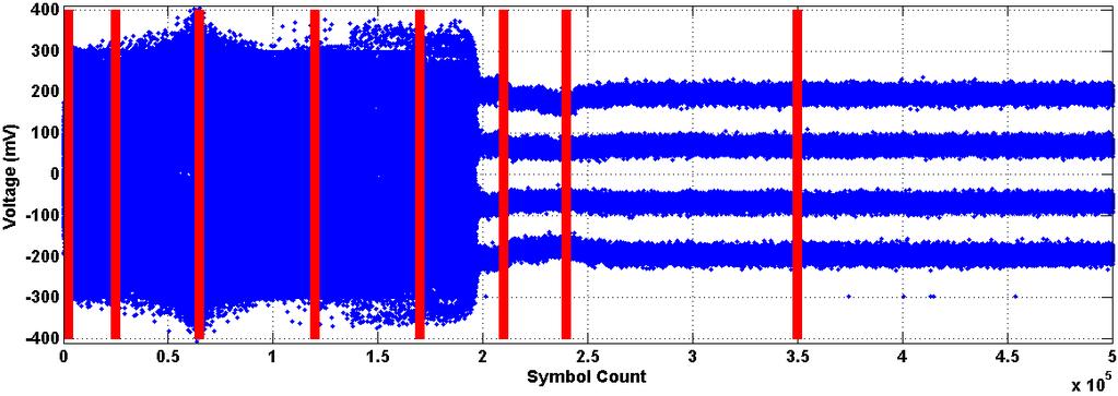
49 MM Baud-Rate CDR Tracking Example For an MR channel at 40Gbps, in a quarter-rate clocking system, with 64 codes/symbol Single tone SJ, amplitude and frequency, was altered dynamically during simulations 6UI 50KHz Started with 0.1UI@10MHz 0.2UI 5MHz 0.3UI 1MHz 0.6UI 500KHz 1.2UI 250KHz 3UI 100KHz For the last SJ, we only see settled half a cycle: the duration, each UI=50ps, is (2.975M M)*50ps = 10ms. So a full cycle is 20ms, or 50KHz The first mark is up by 148, and the second down by =236. So the total swing is =384, or 389/64 = 6UI


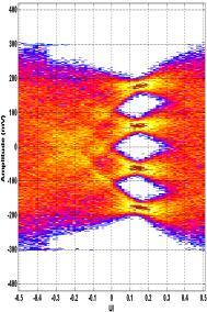
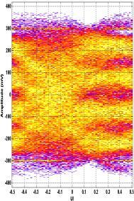
50 MM Baud-Rate CDR Tracking Example Con t To assure that the CDR is indeed in tracking, the sampled eyes are plotted
51 TX FIR Implementation Example MSB and LSB are filtered separately, before being summed up MSB and LSB are coded and mapped to PAM4 levels first before passing through the FIR filter 3 Tap FIR Coefficients MSB P 2 S 2X Current Steering DAC and Driver 3 Tap FIR Coefficients 1X Current Steering DAC and Driver P 2 S LSB Data DSP P 2 S N bit Control Signal Current Steering DAC and Driver d LSB k = c(1)* d LSB k c(0)* d LSB k c( 1)* d LSB k 1 d MSB k = c(1)* d MSB k c(0)* d MSB k c( 1)* d MSB k 1 d PAM4 k = c(1)* d k c(0)*d k c( 1)*d k 1


52 Transmitter De-Emphasis Example Typically, a 3-tap FIR (pre + main + post) TX de-emphasis is used 3-tap FIR results in 4^3 = 64 possible distinct signal levels An example for a 10dB link {C(-1), C(0), C(1)} = {-0.1, 0.675, } The TX output eye is totally distorted, while the eye after the channel is open Channel

53 Channel Equalization with CTLE Example The CTLE works the same for PAM4 as for NRZ signaling The CTLE is usually followed and/or preceded by AGC
 To support raw BER<1e-6, instead of raw BER<-15 The BER is still dominantly affected by deterministic jitter and noise May require")
54 EH6 and EW6 Since PAM4 is essentially a non-error-free system, eye metrics are defined in the VSR sped at BER = 1e-6 EH6 is the vertical distance across the BER = 1e-6 contour EW6 is the horizontal distance across the BER = 1e-6 contour Vertical Eye Closure (VEC) To support raw BER<1e-6, instead of raw BER<-15 The BER is still dominantly affected by deterministic jitter and noise May require redefining link budget to make tradeoffs between performance, power consumption, and implementation cost

55 Analog- vs. Digital- Based Receiver A lot of experience and circuits can be leveraged from decades design of NRZ receivers Power is still an advantage over digital-based receiver architecture As link margin gets smaller, each block needs to be fine-tuned CTLE/AGC Analog FFE DFE A common trend has been the increasing use of DSP Benefits: greater flexibility and more powerful signal processing techniques Challenges: architecture complexity and large power dissipation

56 Tap-Unrolling DFE Example 4 data slicers are needed for one symbol tap DFE unrolling in full-rate clocking mode For half-rate clocking mode 8 data slicers are required For two symbol tap unrolling DFE, the illustration requires 4^2 = 16 slicers is for the fullrate clock scheme, and 32 slicers for the half-rate clocking scheme data in hn X + X hn-1 3h1 + 3h2 X 3h1 + h2 3h1 h2 3h1 3h2 h1 + 3h2 h1 + h2 h1 h2 h1 3h2 h3 Z Z -1 M U X M U X h1 + 3h2 -h1 + h2 -h1 h2 -h1 3h2-3h1 + 3h2-3h1 + h2-3h1 h2-3h1 3h Z -1 Z -1 M U X M U X Z -1 M U X decision out

57 FFE+DFE Example in Analog Receiver A simplified block diagram of a 4-tap FFE and 5-tap DFE is shown The data path includes a bank of 4 S/H, source follower buffers to drive the sampled data to four parallel RX slices, and DFE feedback logic A quarter-rate architecture is chosen for the receiver to establish data signals for a 4-tap FFE Analog FFE can also be implemented using delay lines
58 Analog FFE based on Delay Line Design Example Passive delay element Active delay element

59 Analog-based Equalization Besides TX FIR, the RX side usually contains CTLE/AGC and DFE Analog FFE is also a choice targeting channels beyond VSR An example is illustrated with eyes at different nodes


60 A 20-tap FFE and 1-tap DFE Example
 can mitigate long-tail ISI.")
61 Infinite Impulse Response (IIR) for DFE DFE with the addition of IIR filtering can efficiently cancel many post-cursor ISI terms The CTLE with well placed poles and zeros (low to mid frequency peaking) can mitigate long-tail ISI. However, it may also amplify noise and crosstalk The FIR tap DFE can also do the job but may need many taps, thus increasing implementation complexity and SerDes power consumption 61


62 3-tap TX FIR + RX CTLE + 2-tap DFE TX IIR for a 25dB Channel Example 3-tap TX FIR + 3-tap TX IIR + RX CTLE BER ~2.5e-5 BER ~2.2e-7

63 Necessity for Equalizer Adaptations Equalizer adaptation is important It relieves the burden of relying on manually searching for optimal settings For complicated equalizers it is impossible to tune the parameters manually Most valuably, adaptation can compensate for link characteristic change due to environmental impact, such as temperature AGC and CTLE convergence 5-tap FFE coefficient convergence 5-tap DFE coefficient convergence
64 Visualization of Eye Convergence


65 For analog-based receiver, the familiar eye monitor (a.k.a., eye scope, eye scan, etc.) concept still applies An example is given below On-Die Eye Monitors On-die captured eye Page 65

66 Sampled Eyes For ADC-based architecture, with reasonable amount of power and area, only one sample per symbol is available. Thus, we can only get the so-called sampled eye Page 66
 becomes P i j is the probability of receiving symbol j")

67 SER and BER Calculations For PAM4 (M=4) BER calculations, assuming that all M symbols are equiprobable, SER (symbol error ratio) becomes P i j is the probability of receiving symbol j when symbol i was transmitted. The BER is dependent on the coding scheme of the symbols, where the d i j is the Hamming distance between the labels of symbols i and j. The BER can be approximated as Page 67
, even in a simulation with a couple of million of symbols, there would be decision errors.")
68 BER Estimations For analog based receiver, the margin can be derived using vertical and horizontal bathtub curves, very similar to the case in NRZ For ADC-based receiver architecture, MSE-based BER is often used When BER is high (>1e-6), even in a simulation with a couple of million of symbols, there would be decision errors. Thus, the statistical method introduced above needs to be modified This is true because cross data slicer samples need to be identified and treated differently An example here shows that there are quite a few cross-boundary samples. They are registered on the negative side Page 68

69 Precoding to Reduce DFE Burst Errors A good tutorial on this subject can be found in in Precoding proposal for PAM4 modulation, 100Gb/s Backplane and Cable Task Force, IEEE 802.3, September 2011 A highlight is duplicated below
, we experienced symbol error run-length as large as 11 When precoding is enabled (On), the symbol error run-length is no more than 2 Burst")
70 Precoding Benefit Example A challenging link is used as an example such that we will encounter many errors The RX equalizer includes a 1-tap DFE 3M symbols are simulated and the last 2M are used for analysis It is seen that when precoding is not enabled (Off), we experienced symbol error run-length as large as 11 When precoding is enabled (On), the symbol error run-length is no more than 2 Burst error run length of only up to 2 for 1-tap DFE is not always guaranteed

71 TX and RX Signaling Process with Precoding 2
72 FEC Adopted in IEEE P802.3bj and P802.3bs FEC encoding introduces redundancy into the codeword A block of k data symbols becomes a codeword of n symbols, (n, k) The FEC decoding finds the decoded codeword that is closest to the received codeword The FEC decoding is guaranteed to correct T erred symbols in a received codeword. Reed-Solomon FEC coding (RS-FEC) examples RS(528, 514, T=7, M=10), is proposed in IEEE P802.3bj for 25G NRZ RS(544, 514, T=15, M=10), is proposed in IEEE P802.3bj for 28G PAM4 RS(544, 514, T=15, M=10), is proposed in IEEE P802.3bs for 56G PAM4 KP4 FEC Example 514 2x15=30 Data Parity RS(544, 514) At its most effective, KP4-FEC can correct as many as 150 bit errors in 5440 bits At the other extreme, KP4-FEC can correct no more than 15 bit errors in 5440 bits If 16 bit errors are distributed across 16 different 10-bit symbols, KP4 FEC simply cannot correct them
73 FEC Error Correction Capability Coding Gain The coding gain is the reduction in SNR (db) that can be accommodated while still achieving the desired BER. Under normal link operation conditions, test from system houses showed that RS(528, 514) (KR4 FEC) presents about 5 6 db coding gain RS(544, 514) (KP4 FEC) presents about 7 8 db coding gain Example of Input vs Output BER for several well known FEC codes: G.709: RS8 (255,239) 6.7% IEEE KR4: RS10 (528,514) 3.5% IEEE KP4: RS10 (544, 514) 5.8% BCH-BCH (I.9, G.975.1) : 6.7% Shannon limit for 6.7% OH (G.709 rate) The plot assumes normal, uniform random distribution (Additive White Gaussian Noise) Need to keep in mind the over-clocking induced SNR loss when using FEC
74 Channel Operating Margin (COM) for PAM4 COM is a FOM for a passive electrical channel, based on data eye formalization COM has assumed a practical TX and RX equalization capability. COM has defined detailed calculation of crosstalk and ISI distributions, rather than simply treating them as Gaussian distribution. COM does not consider CDR timing, but allows some margin in computed result COM reference code can be found at There have proposals to modify the current COM parameters or to modify parameters ranges or to add new parameters to better represent 56G-PAM4, MR and LR, designs One needs to understand advantages and disadvantages of the COM approach before using it to assess the link channel Time domain simulations using hardware correlated models are a more sophisticated approach
75 IBIS-AMI Modeling for PAM4 Signaling IBIS-AMI modeling for NRZ signaling is widely accepted in the industry IBIS-AMI modeling for PAM4 signaling is still new, but both silicon makers and EDA tool developers are working toward this goal An example is provided here, based on Keysight ADS system, to show the simulation flow

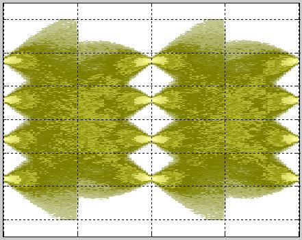
76 PAM4 IBIS-AMI Simulation Example An AMI model, for a 16nm design, was run for an MR channel at 56Gbps in ADS The eye diagram and BER contours for the 3 separate eyes are plotted below The post-processed statistical BER is 4.95e-10

 random Jitter (RJ), periodic Jitter (PJ), (3) Even-Odd (F/2) Jitter")
77 Test Patterns: JP03A and JP03B JP03A test pattern It is a repeating {0, 3} pattern for measuring RJ and deterministic clock jitter JP03B test pattern It is a repeating sequence of 15x {0, 3} followed by 16x{3,0} JP03B is an ideal pattern to measure (1) random Jitter (RJ), periodic Jitter (PJ), (3) Even-Odd (F/2) Jitter (EOJ)
78 Transmitter Even-Odd Jitter (EOJ) EOJ is determined using the following procedure: Use the JP03B test pattern Capture the time for each of the 60 transitions. (Averaging of the vertical waveform or of each zero-crossing time is recommended to mitigate the contribution of uncorrelated noise and jitter.) Denote the averaged zero-crossing times as T ZC (i), where i = {1,2,...60} and where i = 1 designates the transition from 3 to 0 after the consecutive symbols 3 and 3 The set of 40 pulse widths, ΔT(j), isolated from the double-width pulses are determined using the relationship: EOJ is calculated as
 T ZC (39) T ZC (60) Computed EOJ = 1.56/2 = 0.78 ps This is 2.")
79 Transmitter EOJ Computation Example T ZC (1) T ZC (9) T ZC (31) T ZC (32) T ZC (39) T ZC (60) Computed EOJ = 1.56/2 = 0.78 ps This is 2.18% UI

80 Potential Test Pattern 1 QPRBS13 A short while spectrally rich and statistically well-behaved pattern is important for eye metric test, such as signal levels, the mean thickness and distributions, and eye vertical alignment, etc. Quaternary PRBS13 (QPRBS13) pattern is potentially a good candidate The QPRBS13 test pattern is a repeating 8191-symbol sequence Each test pattern is encoded as a digital input from a PRBS13 generator Two full cycles of 8191 bits are concatenated to form the bit sequence, R(1:16382) Bits in the first cycle, R(1:8191) are non-inverted Bits in the second cycle, R(8192:16382), are inverted
 pattern It is a natural generalization of PRBS to")
 arithmetic based LFSRs or by multiplexing 2 appropriate PRBS")

81 Potential Test Pattern 2 PRQS10 Another good candidate is PRQS (Pseudo Random Quaternary Sequence) pattern It is a natural generalization of PRBS to quaternary sequences for PAM4 PRQS patterns can be generated algorithmically using either GF(4) arithmetic based LFSRs or by multiplexing 2 appropriate PRBS patterns The proposed PRQS10 has desirable statistical properties for emulating random PAM4 data, provides good baseline wander characteristics, and has modest length ~ 1M symbols
82 Transmitter Nonlinearity Level Mismatch R LM The level separation mismatch ratio, R LM, is specified as >= 0.95 for MR and LR, based on CEI-56G-PAM4 baseline specs Transmitter linearity test pattern It is a repeating 160-symbol pattern with a sequence of 10 symbol values each 16 UI in duration The 10 values are {-1, 1/3,+1/3,+1, 1,+1, 1,+1,+1/3, 1/3}

83 Modeling R LM This is a proposal at OIF, October, 2015, Shanghai, by Keysight Page 83

84 R LM Impact Example Once R LM profile is defined, its impact on link margin can be simulated An example is shown here of 3 different values of R LM whose profile is defined below


85 Test Equipment for 56G PAM4 As always, test equipment companies are working proactively to provided all kinds of equipment for 56G PAM4 signaling test and measurement, both electrical and optical A few examples are listed below. For details please contact your instrument vendors


86 ADC Analog-to-Digital Converter AGC Automatic Gain Control AMI Algorithmic Modeling Interface BER Bit Error Ratio CEI Common Electrical Interface COM Channel Operating Margin CTLE Continuous Time Linear Equalizer C2C Chip-to-Chip C2M Chip-to-Module DFE Decision Feedback Equalization DSP Digital Signal Processor EDA Electronic Design Automation EOJ Even-Odd Jitter EP Error Propagation EQ Equalization FEC Forward Error Correction FEXT Far End Crosstalk FFE Feed-Forward Equalization Glossaries FIR Finite Impulse Response FOM Figure Of Merit IBIS Input/output Buffer Information Specification ICR Insertion Loss to Crosstalk Ratio ICN Integrated Crosstalk Noise ILD Insertion Loss Deviation IIR Infinite Impulse Response IPR Impulse Response ISI Inter Symbol Interference LR Long Reach LSB Least Significant Bit MR Medium Reach MM Mueller-Muller MMSE Minimum Mean Square Error MSB Most Significant Bit MSE Mean Square Error NEXT Near End Crosstalk NRZ Non-Return-to-Zero OIF Optical Internetworking Forum PAM Pulse Amplitude Modulation PHY Physical Layer PRBS Pseudo Random Binary Sequence PRQS Pseudo Random quaternary Sequence PSFEXT Power Sum of FEXT PSD Power Spectral Density PSNEXT Power Sum of NEXT PSXT Power Sum of Crosstalk QPRBS Quaternary PRBS RMS Root Mean Square SBR Single Bit Response SER Symbol Error Ratio SNR Signal-to-Noise Ratio TD Transition Density VEC Vertical Eye Closure VSR - Very Short Reach

87 References (1) Matthew Brown, et. al, The state of IEEE 802.3bj 100 Gb/s Backplane Ethernet, DesignCon 2014 Nathan Tracy, et al, Evolution of System Electrical Evolution of System Electrical Interfaces Towards 400G Transport Interfaces Towards 400G Transport, OIF, Sep Chris Cole, et. al, PAM-N Tutorial Material, 802.3bj 100 Gb/s Backplane and Copper Cable Task Force, January 2012 Richard Mellitz, et. al, Channel Operating Margin (COM): Evolution of Channel Specifications for 25 Gbps and Beyond, DesignCon 2013 Keysight, PAM-4 Solutions for Transmit and Receive Design Characterization, 23 October 2014 Faisal A. Musa, HIGH-SPEED BAUD-RATE CLOCK RECOVERY, University of Toronto, 2008 Vasu Parthasarathy, PAM4 digital receiver performance and feasibility, January 2012 David R Stauffer, et. al, Comparison of PAM-4 and NRZ Signaling, March 10, 2004 Siamak Sarvari, A 5Gb/s Speculative DFE for 2x Blind ADC-based Receivers in 65-nm CMOS, University of Toronto, 2010 Shirin Farrahi, et al, Does skew really degrade SERDES performance?, DesignCon 2015 Cathy Liu, et. al, 100 Gb/s: The High Speed Connectivity Race is On, Accelerating Innovation, Conference & Technology Showcase, Oct. 5-7, 2010

88 References (2) Mike Li, et al, CEI-56G-MR-PAM4 Medium Reach Interface, OIF Edward Frlan, et al, CEI-56G-VSR-PAM4 Very Short Reach Interface, OIF Mike Li, et al, CEI-56G-LR-PAM4 Long Reach Interface, OIF Jri Lee, et al, Design and Comparison of Three 20-Gb/s Backplane Transceivers for Duobinary, PAM4, and NRZ Data, IEEE JSSC, VOL. 43, NO. 9, Sep Ed Frlan, 56Gbps Serial Why, What, When, OIF Panel Session at 2014 OFC Sam Palermo, ECEN689: Special Topics in High-Speed Links Circuits and Systems, Texas A&M University E-Hung Chen, ADC-based Serial I/O Receivers, University of California, Los Angeles Yuval Domb, et al, PAM4 MODULATION FOR THE 400G ELECTRICAL INTERFACE, IEEE 802.3bs 400Gb/s Task Force, July 2014 Plenary Vladimir Stojanovic, Autonomous Dual-Mode (PAM2/4) Serial Link Transceiver With Adaptive Equalization and Data Recovery, IEEE JSSC, Vol. 40, No. 4, April 2005 Ransom Stephens, Why FEC plays nice with DFE, EDN, May 2015 Klaus-Holger Otto, et al, Proposal for CEI-56G FEC Requirements Section, OIF , July 2015 Fangyi Rao, et al, New Interconnect Models Removes Simulation Uncertainty, IBIS Summit, Feb., 2008
, 56Gs/s ADC Enabling 100GbE, OFC2010 Invited Paper, Digital Transmission Systems Philip Fisher, et al, 56Gbps ASIC Transceiver Measured Results, OIF2014.")
89 References (3) Ankur Agrawal, et al, A 19-Gb/s Serial Link Receiver With Both 4-Tap FFE and 5-Tap DFE Functions in 45-nm SOI CMOS, IEEE JSSC, Vol 47, No. 12, 2012 Ian Dedic (Fujitsu), 56Gs/s ADC Enabling 100GbE, OFC2010 Invited Paper, Digital Transmission Systems Philip Fisher, et al, 56Gbps ASIC Transceiver Measured Results, OIF , October, 2014 Hongtao Zhang, et al, IBIS-AMI Modeling and Simulation of 56G PAM4 Link Systems, DesignCon 2015 Jared L. Zerbe, et al, Equalization and Clock Recovery for a Gb/s 2-PAM/4-PAM Backplane Transceiver Cell, JSSC, VOL. 38, NO. 12, Dec Adam Healey, et al, CDAUI-8 chip-to-module and chip-to-chip interfaces using PAM4, IEEE P802.3bs 400 GbE Task Force meeting Nov S. Shahramian, et al, "A 10Gb/s 4.1mW 2-IIR + 1-discrete-tap DFE in 28nm-LP CMOS," ESSCIRC, 2014 Steve Sekel, Linearity stressed input test proposal for PAM-4, oif , October, 2015 Krzysztof Szczerba, et al, 4-PAM for High-Speed Short-Range Optical Communications, J. Opt. Commu. New., Vol. 4, No., 11, 2012 Cathy Liu, et al, Channel operating margin (COM) for 56G-LR PAM4, oif , Oct Osama Elhadidy, et al, A 32 Gb/s 0.55 mw/gbps PAM4 1-FIR 2-IIR Tap DFE Receiver in 65-nm CMOS, 2015 Symposium on VLSI Circuits Digest of Technical Papers

90 References (4) Xiaoqing Dong, et al, Relating COM to Familiar S-Parameter Parametric to Assist 25Gbps System Design, DesignCon 2014 Tektronix, Application Note, PAM4 Signaling in High Speed Serial Technology: Test, Analysis, and Debug Adee Ran, 100GBASE-KP4 jitter and distortion specification proposal, IEEE P802.3bj 100 Gb/s Backplane and Copper Cable September 2013 Moonkyun Maeng, et al, 0.18-µm CMOS Equalization Techniques for 10-Gb/s Fiber Optical Communication Links, IEEE Trans. Microw. Theory Tech, vol 53, no. 11, Nov, 2005 Ilya Lyubomirsky, PRQS Test Patterns for PAM4, IEEE802.3bs 400GbE Task Force, Sep., 2015 Ken Ly, et al, Channel Mode Conversion Impact on PAM4 Link Performance, oif , Oct G. Sheets et al, Evaluating Environmental Impact on Channel Performance, CommDesign, May 2004 Richard Mellitz, et al, Channel Operating Margin (COM): Evolution of Channel Specifications for 25 Gbps and Beyond, DesignCon 2013
91 Thank You! --- QUESTIONS?
100Gb/s Single-lane SERDES Discussion. Phil Sun, Credo Semiconductor IEEE New Ethernet Applications Ad Hoc May 24, 2017
 100Gb/s Single-lane SERDES Discussion Phil Sun, Credo Semiconductor IEEE 802.3 New Ethernet Applications Ad Hoc May 24, 2017 Introduction This contribution tries to share thoughts on 100Gb/s single-lane
Comparison of NRZ, PR-2, and PR-4 signaling. Qasim Chaudry Adam Healey Greg Sheets
 Comparison of NRZ, PR-2, and PR-4 signaling Presented by: Rob Brink Contributors: Pervez Aziz Qasim Chaudry Adam Healey Greg Sheets Scope and Purpose Operation over electrical backplanes at 10.3125Gb/s
The Case of the Closing Eyes: Is PAM the Answer? Is NRZ dead?
 The Case of the Closing Eyes: Is PAM the Answer? Is NRZ dead? Agenda Introductions Overview Design Engineering Perspective Test & Measurement Perspective Summary Audience Discussion Panelists Cathy Liu
Draft Baseline Proposal for CDAUI-8 Chipto-Module (C2M) Electrical Interface (NRZ)
 Electrical Interface (NRZ)") Draft Baseline Proposal for CDAUI-8 Chipto-Module (C2M) Electrical Interface (NRZ) Authors: Tom Palkert: MoSys Jeff Trombley, Haoli Qian: Credo Date: Dec. 4 2014 Presented: IEEE 802.3bs electrical interface
Draft Baseline Proposal for CDAUI-8 Chipto-Module (C2M) Electrical Interface (NRZ) Authors: Tom Palkert: MoSys Jeff Trombley, Haoli Qian: Credo Date: Dec. 4 2014 Presented: IEEE 802.3bs electrical interface
Brian Holden Kandou Bus, S.A. IEEE GE Study Group September 2, 2013 York, United Kingdom
 Simulation results for NRZ, ENRZ & PAM-4 on 16-wire full-sized 400GE backplanes Brian Holden Kandou Bus, S.A. brian@kandou.com IEEE 802.3 400GE Study Group September 2, 2013 York, United Kingdom IP Disclosure
Half-Rate Decision-Feedback Equalization Di-Bit Response Analysis and Evaluation EDA365
 DesignCon 2008 Half-Rate Decision-Feedback Equalization Di-Bit Response Analysis and Evaluation Jihong Ren, Rambus Inc. jren@rambus.com Brian Leibowitz, Rambus Inc. Dan Oh, Rambus Inc. Jared Zerbe, Rambus
Further Investigation of Bit Multiplexing in 400GbE PMA
 Further Investigation of Bit Multiplexing in 400GbE PMA Tongtong Wang, Xinyuan Wang, Wenbin Yang HUAWEI TECHNOLOGIES CO., LTD. IEEE 802.3bs 400 GbE Task Force Introduction and Background Bit-Mux in PMA
A Way to Evaluate post-fec BER based on IBIS-AMI Model
 A Way to Evaluate post-fec BER based on IBIS-AMI Model Yu Yangye, Guo Tao, Zhu Shunlin yu.yangye@zte.com.cn,guo.tao6@zte.com.cn,zhu.shunlin@zte.com.cn Asian IBIS Summit, Shanghai, China, November 13, 2017
Practical Receiver Equalization Tradeoffs Applicable to Next- Generation 28 Gb/s Links with db Loss Channels
 DesignCon 2013 Practical Receiver Equalization Tradeoffs Applicable to Next- Generation 28 Gb/s Links with 20 35 db Loss Channels Edward Frlan, Semtech Corp. (EFrlan@semtech.com) Francois Tremblay, Semtech
Combating Closed Eyes Design & Measurement of Pre-Emphasis and Equalization for Lossy Channels
 Combating Closed Eyes Design & Measurement of Pre-Emphasis and Equalization for Lossy Channels Why Test the Receiver? Serial Data communications standards have always specified both the transmitter and
Combating Closed Eyes Design & Measurement of Pre-Emphasis and Equalization for Lossy Channels
 Combating Closed Eyes Design & Measurement of Pre-Emphasis and Equalization for Lossy Channels Why Test the Receiver? Serial Data communications standards have always specified both the transmitter and
32 G/64 Gbaud Multi Channel PAM4 BERT
 Product Introduction 32 G/64 Gbaud Multi Channel PAM4 BERT PAM4 PPG MU196020A PAM4 ED MU196040A Signal Quality Analyzer-R MP1900A Series Outline of MP1900A series PAM4 BERT Supports bit error rate measurements
CDAUI-8 Chip-to-Module (C2M) System Analysis #3. Ben Smith and Stephane Dallaire, Inphi Corporation IEEE 802.3bs, Bonita Springs, September 2015
 System Analysis #3. Ben Smith and Stephane Dallaire, Inphi Corporation IEEE 802.3bs, Bonita Springs, September 2015") CDAUI-8 Chip-to-Module (C2M) System Analysis #3 Ben Smith and Stephane Dallaire, Inphi Corporation IEEE 802.3bs, Bonita Springs, September 2015 Supporters Ali Ghiasi, Ghiasi Quantum LLC Marco Mazzini,
CDAUI-8 Chip-to-Module (C2M) System Analysis #3 Ben Smith and Stephane Dallaire, Inphi Corporation IEEE 802.3bs, Bonita Springs, September 2015 Supporters Ali Ghiasi, Ghiasi Quantum LLC Marco Mazzini,
PAM4 signals for 400 Gbps: acquisition for measurement and signal processing
 TITLE PAM4 signals for 400 Gbps: acquisition for measurement and signal processing Image V1.00 1 Introduction, content High speed serial data links are in the process in increasing line speeds from 25
LOW POWER DIGITAL EQUALIZATION FOR HIGH SPEED SERDES. Masum Hossain University of Alberta
 LOW POWER DIGITAL EQUALIZATION FOR HIGH SPEED SERDES Masum Hossain University of Alberta 0 Outline Why ADC-Based receiver? Challenges in ADC-based receiver ADC-DSP based Receiver Reducing impact of Quantization
CDAUI-8 Chip-to-Module (C2M) System Analysis. Stephane Dallaire and Ben Smith, September 2, 2015
 System Analysis. Stephane Dallaire and Ben Smith, September 2, 2015") CDAUI-8 Chip-to-Module (C2M) System Analysis Stephane Dallaire and Ben Smith, September 2, 2015 Introduction (1) Follow-up to previous ad hoc contribution on the merits of various reference receiver architectures
CDAUI-8 Chip-to-Module (C2M) System Analysis Stephane Dallaire and Ben Smith, September 2, 2015 Introduction (1) Follow-up to previous ad hoc contribution on the merits of various reference receiver architectures
100G EDR and QSFP+ Cable Test Solutions
 100G EDR and QSFP+ Cable Test Solutions (IBTA, 100GbE, CEI) DesignCon 2017 James Morgante Anritsu Company Presenter Bio James Morgante Application Engineer Eastern United States james.morgante@anritsu.com
On Figure of Merit in PAM4 Optical Transmitter Evaluation, Particularly TDECQ
 On Figure of Merit in PAM4 Optical Transmitter Evaluation, Particularly TDECQ Pavel Zivny, Tektronix V1.0 On Figure of Merit in PAM4 Optical Transmitter Evaluation, Particularly TDECQ A brief presentation
Duobinary Transmission over ATCA Backplanes
 Duobinary Transmission over ATCA Backplanes Majid Barazande-Pour John Khoury November 15-19, 2004 IEEE 802.3ap Backplane Ethernet Task Force Plenary Meeting San Antonio Texas Outline Introduction Adaptive
Exceeding the Limits of Binary Data Transmission on Printed Circuit Boards by Multilevel Signaling
 Exceeding the Limits of Binary Data Transmission on Printed Circuit Boards by Multilevel Signaling Markus Grözing, Manfred Berroth INT, in cooperation with Michael May Agilent Technologies, Böblingen Prof.
Ali Ghiasi. Nov 8, 2011 IEEE GNGOPTX Study Group Atlanta
 Ali Ghiasi Nov 8, 2011 IEEE 802.3 100GNGOPTX Study Group Atlanta 1 Overview I/O Trend Line card implementations VSR/CAUI-4 application model cppi-4 application model VSR loss budget Possible CAUI-4 loss
AMI Simulation with Error Correction to Enhance BER
 DesignCon 2011 AMI Simulation with Error Correction to Enhance BER Xiaoqing Dong, Huawei Technologies Dongxiaoqing82@huawei.com Geoffrey Zhang, Huawei Technologies geoff.zhang@huawei.com Kumar Keshavan,
Comment #147, #169: Problems of high DFE coefficients
 Comment #147, #169: Problems of high DFE coefficients Yasuo Hidaka Fujitsu Laboratories of America, Inc. September 16-18, 215 IEEE P82.3by 25 Gb/s Ethernet Task Force Comment #147 1 IEEE P82.3by 25 Gb/s
The Challenges of Measuring PAM4 Signals
 TITLE The Challenges of Measuring PAM4 Signals Panelists: Doug Burns, SiSoft Stephen Mueller, Teledyne LeCroy Luis Boluña, Keysight Technologies Mark Guenther, Tektronix Image Jose Moreira, Advantest Martin
Clause 74 FEC and MLD Interactions. Magesh Valliappan Broadcom Mark Gustlin - Cisco
 Clause 74 FEC and MLD Interactions Magesh Valliappan Broadcom Mark Gustlin - Cisco Introduction The following slides investigate whether the objectives of the Clause 74 FEC* can be met with MLD for KR4,
MR Interface Analysis including Chord Signaling Options
 MR Interface Analysis including Chord Signaling Options David R Stauffer Margaret Wang Johnston Andy Stewart Amin Shokrollahi Kandou Bus SA May 12, 2014 Kandou Bus, S.A 1 Contribution Number: OIF2014.113
ECEN689: Special Topics in High-Speed Links Circuits and Systems Spring 2011
 ECEN689: Special Topics in High-Speed Links Circuits and Systems Spring 2011 Lecture 9: TX Multiplexer Circuits Sam Palermo Analog & Mixed-Signal Center Texas A&M University Announcements & Agenda Next
Problems of high DFE coefficients
 Problems of high DFE coefficients Yasuo Hidaka Fujitsu Laboratories of America, Inc. September, 5 IEEE P8.3by 5 Gb/s Ethernet Task Force Abstract If we allow high DFE coefficients, we cannot meet MTTFPA
Proposal for 10Gb/s single-lane PHY using PAM-4 signaling
 Proposal for 10Gb/s single-lane PHY using PAM-4 signaling Rob Brink, Agere Systems Bill Hoppin, Synopsys Supporters Ted Rado, Analogix John D Ambrosia, Tyco Electronics* * This contributor supports multi-level
10 Gb/s Duobinary Signaling over Electrical Backplanes Experimental Results and Discussion
 10 Gb/s Duobinary Signaling over Electrical Backplanes Experimental Results and Discussion J. Sinsky, A. Adamiecki, M. Duelk, H. Walter, H. J. Goetz, M. Mandich contact: sinsky@lucent.com Supporters John
Summary of NRZ CDAUI proposals
 Summary of NRZ CDAUI proposals Piers Dawe Tom Palkert Jeff Twombly Haoli Qian Mellanox Technologies MoSys Credo Semiconductor Credo Semiconductor Contributors Scott Irwin Mike Dudek Ali Ghiasi MoSys QLogic
Presentation to IEEE P802.3ap Backplane Ethernet Task Force July 2004 Working Session
 Presentation to IEEE P802.3ap Backplane Ethernet Task Force July 2004 Working Session Title: PAM-4 versus NRZ Signaling: "Basic Theory" Source: John Bulzacchelli Troy Beukema David R Stauffer Joe Abler
Update on FEC Proposal for 10GbE Backplane Ethernet. Andrey Belegolovy Andrey Ovchinnikov Ilango. Ganga Fulvio Spagna Luke Chang
 Update on FEC Proposal for 10GbE Backplane Ethernet Andrey Belegolovy Andrey Ovchinnikov Ilango Ganga Fulvio Spagna Luke Chang 802.3ap FEC Proposal IEEE802.3ap Plenary Meeting Vancouver, Nov14-17 2005
Systematic Tx Eye Mask Definition. John Petrilla, Avago Technologies March 2009
 Systematic Tx Eye Mask Definition John Petrilla, Avago Technologies March 2009 Presentation Overview Problem statement & solution Comment Reference: P802.3ba D1.2, Comment 97 Reference Material Systematic
40G SWDM4 MSA Technical Specifications Optical Specifications
 40G SWDM4 MSA Technical Specifications Specifications Participants Editor David Lewis, LUMENTUM The following companies were members of the SWDM MSA at the release of this specification: Company Commscope
Analyzing GBaud PAM4 Optical and Electrical Signals APPLICATION NOTE
 Analyzing 26-53 GBaud PAM4 Optical and Electrical Signals Contents 1. Introduction... 3 2. Current PAM4 Technologies... 4 3. Debugging PAM4 Systems and Transceivers... 7 3.1 Test setup and concepts...7
More Insights of IEEE 802.3ck Baseline Reference Receivers
 More Insights of IEEE 802.3ck Baseline Reference Receivers Yuchun Lu, Huawei Zhilei Huang, Huawei Yan Zhuang, Huawei IEEE 802.3 100 Gb/s, 200 Gb/s, and 400 Gb/s Electrical Interfaces Task Force Table of
System Evolution with 100G Serial IO
 System Evolution with 100G Serial IO Ali Ghiasi GhiasiQuantum LLC 100 Gb/s/Lane NEA Meeting New Orleans May 24th, 2017 Overview q Since 10GBASE-KR superset ASIC SerDes have supported C2M, C2M, and backplane
64G Fibre Channel strawman update. 6 th Dec 2016, rv1 Jonathan King, Finisar
 64G Fibre Channel strawman update 6 th Dec 2016, rv1 Jonathan King, Finisar 1 Background Ethernet (802.3cd) has adopted baseline specs for 53.1 Gb/s PAM4 (per fibre) for MMF links 840 to 860 nm VCSEL based
Receiver Testing to Third Generation Standards. Jim Dunford, October 2011
 Receiver Testing to Third Generation Standards Jim Dunford, October 2011 Agenda 1.Introduction 2. Stressed Eye 3. System Aspects 4. Beyond Compliance 5. Resources 6. Receiver Test Demonstration PCI Express
Further Clarification of FEC Performance over PAM4 links with Bit-multiplexing
 Further Clarification of FEC Performance over PAM4 links with Bit-multiplexing Xinyuan Wang-Huawei Ali Ghiasi- Ghiasi Quantum Tongtong Wang-Huawei Background and Introduction KP4 FEC performance is influenced
Performance comparison study for Rx vs Tx based equalization for C2M links
 Performance comparison study for Rx vs Tx based equalization for C2M links Karthik Gopalakrishnan, Basel Alnabulsi, Jamal Riani, Ilya Lyubomirsky, and Sudeep Bhoja, Inphi Corp. IEEE P802.3ck Task Force
o-microgigacn Data Sheet Revision Channel Optical Transceiver Module Part Number: Module: FPD-010R008-0E Patch Cord: FOC-CC****
 o-microgigacn 4-Channel Optical Transceiver Module Part Number: Module: FPD-010R008-0E Patch Cord: FOC-CC**** Description Newly developed optical transceiver module, FUJITSU s o-microgigacn series supports
IBIS AMI Modeling of Retimer and Performance Analysis of Retimer based Active Serial Links
 DesignCon 2014 IBIS AMI Modeling of Retimer and Performance Analysis of Retimer based Active Serial Links Kian Haur (Alfred) Chong, Texas Instruments Venkatesh Avula, LSI Research and Development, Bangalore,
40G SWDM4 MSA Technical Specifications Optical Specifications
 40G SWDM4 MSA Technical Specifications Specifications Participants Editor David Lewis, LUMENTUM The following companies were members of the SWDM MSA at the release of this specification: Company Commscope
DesignCon Pavel Zivny, Tektronix, Inc. (503)
") DesignCon 2009 New methods of measuring the performance of equalized serial data links and correlation of performance measures across the design flow, from simulation to measurement, and final BER tests
DesignCon 2009 New methods of measuring the performance of equalized serial data links and correlation of performance measures across the design flow, from simulation to measurement, and final BER tests
Powering Collaboration and Innovation in the Simulation Design Flow Agilent EEsof Design Forum 2010
 Powering Collaboration and Innovation in the Simulation Design Flow Agilent EEsof Design Forum 2010 Channel Simulator and AMI model support within ADS Page 1 Contributors to this Paper José Luis Pino,
Investigation of PAM-4/6/8 Signaling and FEC for 100 Gb/s Serial Transmission
 Investigation of PAM-4/6/8 Signaling and FEC for 100 Gb/s Serial Transmission IEEE 802.3bm Task Force Ali Ghiasi, Zhongfeng Wang, and Vivek Telang - Broadcom Brian Welch Luxtera Nov 13-15, 2012 San Antonio,
100GEL C2M Channel Reach Update
 C2M Channel Reach Update Jane Lim, Cisco Pirooz Tooyserkani, Cisco Upen Reddy Kareti, Cisco Joel Goergen, Cisco Marco Mazzini, Cisco 7/11/2018 IEEE P802.3ck 100Gb/s, 200Gb/s, and 400Gb/s Electrical Interfaces
Open electrical issues. Piers Dawe Mellanox
 Open electrical issues Piers Dawe Mellanox My list of list of what needs to be done in 802.3bs before that project can be complete 1. Jitter specs for 400GAUI-8 and 400GBASE-DR4 are not compatible 2. 400GAUI-8
TERRESTRIAL broadcasting of digital television (DTV)
") IEEE TRANSACTIONS ON BROADCASTING, VOL 51, NO 1, MARCH 2005 133 Fast Initialization of Equalizers for VSB-Based DTV Transceivers in Multipath Channel Jong-Moon Kim and Yong-Hwan Lee Abstract This paper
IEEE TRANSACTIONS ON BROADCASTING, VOL 51, NO 1, MARCH 2005 133 Fast Initialization of Equalizers for VSB-Based DTV Transceivers in Multipath Channel Jong-Moon Kim and Yong-Hwan Lee Abstract This paper
BRR Tektronix BroadR-Reach Compliance Solution for Automotive Ethernet. Anshuman Bhat Product Manager
 BRR Tektronix BroadR-Reach Compliance Solution for Automotive Ethernet Anshuman Bhat Product Manager anshuman.bhat@tektronix.com Agenda BroadR-Reach Automotive Market Technology Overview Open Alliance
FEC Applications for 25Gb/s Serial Link Systems
 FEC Applications for 25Gb/s Serial Link Systems Guo Tao,Zhu Shunlin Guo.tao6@zte.com.cn, zhu.shunlin@zte.com.cn Asian IBIS Summit, Shanghai, China, November 9, 2015 Agenda Introduction FEC Applications
DataCom: Practical PAM4 Test Methods for Electrical CDAUI8/VSR-PAM4, Optical 400G-BASE LR8/FR8/DR4
 DataCom: Practical PAM4 Test Methods for Electrical CDAUI8/VSR-PAM4, Optical 400G-BASE LR8/FR8/DR4 400G Ecosystem (shown for comparison) Ethernet (highly leveraged PAM4) CFP8 Blade Servers CDAUI-8, CDAUI-16
New Serial Link Simulation Process, 6 Gbps SAS Case Study
 ew Serial Link Simulation Process, 6 Gbps SAS Case Study Donald Telian SI Consultant Session 7-TH2 Donald Telian SI Consultant About the Authors Donald Telian is an independent Signal Integrity Consultant.
BER margin of COM 3dB
 BER margin of COM 3dB Yasuo Hidaka Fujitsu Laboratories of America, Inc. September 9, 2015 IEEE P802.3by 25 Gb/s Ethernet Task Force Abstract I was curious how much actual margin we have with COM 3dB So,
Investigation of PAM-4/6/8 Signaling and FEC for 100 Gb/s Serial Transmission
 Investigation of PAM-4/6/8 Signaling and FEC for 100 Gb/s Serial Transmission IEEE 802.3bm Task Force Ali Ghiasi, Zhongfeng Wang, and Vivek Telang - Broadcom Brian Welch Luxtera Nov 13-15, 2012 San Antonio,
AMI Modeling Methodology and Measurement Correlation of a 6.25Gb/s Link
 May 26th, 2011 DAC IBIS Summit June 2011 AMI Modeling Methodology and Measurement Correlation of a 6.25Gb/s Link Ryan Coutts Antonis Orphanou Manuel Luschas Amolak Badesha Nilesh Kamdar Agenda Correlation
IBIS AMI Modeling of Retimer and Performance Analysis of Retimer based Active Serial Links
 IBIS AMI Modeling of Retimer and Performance Analysis of Retimer based Active Serial Links Kian Haur (Alfred) Chong, Texas Instruments Venkatesh Avula, LSI Research and Development, Liu Liang, Texas Instruments
Approach For Supporting Legacy Channels Per IEEE 802.3bj Objective
 Approach For Supporting Legacy Channels Per IEEE 802.3bj Objective Jitendra Mohan, Texas Instruments Pravin Patel, IBM Jan 2012, IEEE 802.3bj Meeting, Newport Beach 1 Agenda Approach to enable NRZ over
Measurements and Simulation Results in Support of IEEE 802.3bj Objective
 Measurements and Simulation Results in Support of IEEE 802.3bj Objective Jitendra Mohan, National Semiconductor Corporation Pravin Patel, IBM Zhiping Yang, Cisco Peerouz Amleshi, Mark Bugg, Molex Sep 2011,
PAM8 Baseline Proposal
 PAM8 Baseline Proposal Authors: Chris Bergey Luxtera Vipul Bhatt Cisco Sudeep Bhoja Inphi Arash Farhood Cortina Ali Ghiasi Broadcom Gary Nicholl Cisco Andre Szczepanek -- InPhi Norm Swenson Clariphy Vivek
New Results on QAM-Based 1000BASE-T Transceiver
 New Results on QAM-Based 1000BASE-T Transceiver Oscar Agazzi, Mehdi Hatamian, Henry Samueli Broadcom Corp. 16251 Laguna Canyon Rd. Irvine, CA 92618 714-450-8700 Outline Transceiver parameters 3dB and 10dB
CAUI-4 Chip to Chip Simulations
 CAUI-4 Chip to Chip Simulations IEEE 802.3bm Task Force Ali Ghiasi Broadcom Corporation Jan 22-23, 2013 Phoenix Overview A CAUI-4 chip to chip link with 20 db loss budget require DFE receiver and to avoid
EVALUATION KIT AVAILABLE 12.5Gbps Settable Receive Equalizer +2.5V +3.3V V CC1 V CC. 30in OF FR-4 STRIPLINE OR MICROSTRIP TRANSMISSION LINE SDI+ SDI-
 19-2713; Rev 1; 11/03 EVALUATION KIT AVAILABLE 12.5Gbps Settable Receive Equalizer General Description The driver with integrated analog equalizer compensates up to 20dB of loss at 5GHz. It is designed
Time Domain Simulations
 Accuracy of the Computational Experiments Called Mike Steinberger Lead Architect Serial Channel Products SiSoft Time Domain Simulations Evaluation vs. Experimentation We re used to thinking of results
IBIS-AMI Post-Simulation Analysis
 IBIS-AMI Post-Simulation Analysis Mike LaBonte, Todd Westerhoff SiSoft DesignCon IBIS Summit February 2, 2018 Santa Clara, California IBIS Simulation Post-Processing Support IBIS 1.0: Vinl/Vinh IBIS 2.0:
Development of an oscilloscope based TDP metric
 Development of an oscilloscope based TDP metric IEEE 2015 Greg LeCheminant Supporters Jonathan King Finisar Ali Ghiasi Ghiasi Quantum 2015 Page 2 Understanding the basic instrumentation issues Equivalent-time
M809256PA OIF-CEI CEI-56G Pre-Compliance Receiver Test Application
 M809256PA OIF-CEI CEI-56G Pre-Compliance Receiver Test Application Find us at www.keysight.com Page 1 Table of Contents Key Features... 3 Description... 3 Calibrations and Tests Covered by M809256PA Pre-Compliance
Proposed reference equalizer change in Clause 124 (TDECQ/SECQ. methodologies).
.") Proposed reference equalizer change in Clause 124 (TDECQ/SECQ methodologies). 25th April 2017 P802.3bs SMF ad hoc Atul Gupta, Macom Marco Mazzini, Cisco Introduction In mazzini_01a_0317_smf, some concerns
Proposed reference equalizer change in Clause 124 (TDECQ/SECQ methodologies). 25th April 2017 P802.3bs SMF ad hoc Atul Gupta, Macom Marco Mazzini, Cisco Introduction In mazzini_01a_0317_smf, some concerns
SECQ Test Method and Calibration Improvements
 SECQ Test Method and Calibration Improvements IEEE802.3cd, Geneva, January 22, 2018 Matt Sysak, Adee Ran, Hai-Feng Liu, Scott Schube In support of comments 82-84 Summary We are proposing revising the wording
100GBASE-SR4 Extinction Ratio Requirement. John Petrilla: Avago Technologies September 2013
 100GBASE-SR4 Extinction Ratio Requirement John Petrilla: Avago Technologies September 2013 Presentation Summary Eye displays for the worst case TP1 and Tx conditions that were used to define Clause 95
50 Gb/s per lane MMF baseline proposals. P802.3cd, Whistler, BC 21 st May 2016 Jonathan King, Finisar Jonathan Ingham, FIT
 50 Gb/s per lane MMF baseline proposals P802.3cd, Whistler, BC 21 st May 2016 Jonathan King, Finisar Jonathan Ingham, FIT 1 Supporters Chris Cole, Finisar Doug Coleman, Corning Scott Kipp, Brocade Kent
Technical Article MS-2714
 . MS-2714 Understanding s in the JESD204B Specification A High Speed ADC Perspective by Jonathan Harris, applications engineer, Analog Devices, Inc. INTRODUCTION As high speed ADCs move into the GSPS range,
802.3bj FEC Overview and Status. PCS, FEC and PMA Sublayer Baseline Proposal DRAFT. IEEE P802.3ck
 802.3bj FEC Overview and Status PCS, FEC and PMA Sublayer Baseline Proposal DRAFT IEEE P802.3ck May 2018 Pittsburgh Mark Gustlin - Xilinx Gary Nicholl Cisco Dave Ofelt Juniper Jeff Slavick Broadcom Supporters
Synthesized Clock Generator
 Synthesized Clock Generator CG635 DC to 2.05 GHz low-jitter clock generator Clocks from DC to 2.05 GHz Random jitter
PAM-2 on a 1 Meter Backplane Channel
 PAM-2 on a 1 Meter Backplane Channel Pravin Patel (IBM) Mike Li (Altera) Scott Kipp (Brocade) Adam Healey (LSI) Mike Dudek (Qlogic) Karl Muth (TI) September 2011 1 Supporters Myles Kimmit (Emulex) Fred
Need for FEC-protected chip-to-module CAUI-4 specification. Piers Dawe Mellanox Technologies
 Need for FEC-protected chip-to-module CAUI-4 specification Piers Dawe Mellanox Technologies IEEE P802.3bm, Sept. 2013, York Need for FEC-protected chip-to-module CAUI-4 specification 1 Supporters Yonatan
Next Generation Ultra-High speed standards measurements of Optical and Electrical signals
 Next Generation Ultra-High speed standards measurements of Optical and Electrical signals Apr. 2011, V 1.0, prz Agenda Speeds above 10 Gb/s: Transmitter and Receiver test setup Transmitter Test 1,2 : Interconnect,
The EMC, Signal And Power Integrity Institute Presents
 The EMC, Signal And Power Integrity Institute Presents Module 12 Pre-emphasis And Its Impact On The Eye Pattern And Bit-Error-Rate For High-Speed Signaling By Dr. David Norte Copyright 2005 by Dr. David
Datasheet SHF A Multi-Channel Error Analyzer
 SHF Communication Technologies AG Wilhelm-von-Siemens-Str. 23D 12277 Berlin Germany Phone +49 30 772051-0 Fax +49 30 7531078 E-Mail: sales@shf.de Web: http://www.shf.de Datasheet SHF 11104 A Multi-Channel
SV1C Personalized SerDes Tester
 SV1C Personalized SerDes Tester Data Sheet SV1C Personalized SerDes Tester Data Sheet Revision: 1.0 2013-02-27 Revision Revision History Date 1.0 Document release Feb 27, 2013 The information in this
Optimization of Multi-Channel BCH Error Decoding for Common Cases. Russell Dill Master's Thesis Defense April 20, 2015
 Optimization of Multi-Channel BCH Error Decoding for Common Cases Russell Dill Master's Thesis Defense April 20, 2015 Bose-Chaudhuri-Hocquenghem (BCH) BCH is an Error Correcting Code (ECC) and is used
ECE 5765 Modern Communication Fall 2005, UMD Experiment 10: PRBS Messages, Eye Patterns & Noise Simulation using PRBS
 ECE 5765 Modern Communication Fall 2005, UMD Experiment 10: PRBS Messages, Eye Patterns & Noise Simulation using PRBS modules basic: SEQUENCE GENERATOR, TUNEABLE LPF, ADDER, BUFFER AMPLIFIER extra basic:
Datasheet SHF A
 SHF Communication Technologies AG Wilhelm-von-Siemens-Str. 23D 12277 Berlin Germany Phone +49 30 772051-0 Fax ++49 30 7531078 E-Mail: sales@shf.de Web: http://www.shf.de Datasheet SHF 19120 A 2.85 GSa/s
TDECQ update noise treatment and equalizer optimization (revision of king_3bs_01_0117) 14th February 2017 P802.3bs SMF ad hoc Jonathan King, Finisar
 14th February 2017 P802.3bs SMF ad hoc Jonathan King, Finisar") TDECQ update noise treatment and equalizer optimization (revision of king_3bs_01_0117) 14th February 2017 P802.3bs SMF ad hoc Jonathan King, Finisar 1 Preamble TDECQ calculates the db ratio of how much
TDECQ update noise treatment and equalizer optimization (revision of king_3bs_01_0117) 14th February 2017 P802.3bs SMF ad hoc Jonathan King, Finisar 1 Preamble TDECQ calculates the db ratio of how much
Improving IBIS-AMI Model Accuracy: Model-to-Model and Model-to-Lab Correlation Case Studies
 Improving IBIS-AMI Model Accuracy: Model-to-Model and Model-to-Lab Correlation Case Studies Dong Yang 1, Yunong Gan 1, Vivek Telang 1, Magesh Valliappan 1, Fred S. Tang 1, Todd Westerhoff 2, and Fanyi
100G PSM4 & RS(528, 514, 7, 10) FEC. John Petrilla: Avago Technologies September 2012
 FEC. John Petrilla: Avago Technologies September 2012") 100G PSM4 & RS(528, 514, 7, 10) FEC John Petrilla: Avago Technologies September 2012 Supporters David Cunningham Jon Anderson Doug Coleman Oren Sela Paul Kolesar Avago Technologies Oclaro Corning Mellanox
100G PSM4 & RS(528, 514, 7, 10) FEC John Petrilla: Avago Technologies September 2012 Supporters David Cunningham Jon Anderson Doug Coleman Oren Sela Paul Kolesar Avago Technologies Oclaro Corning Mellanox
Draft 100G SR4 TxVEC - TDP Update. John Petrilla: Avago Technologies February 2014
 Draft 100G SR4 TxVEC - TDP Update John Petrilla: Avago Technologies February 2014 Supporters David Cunningham Jonathan King Patrick Decker Avago Technologies Finisar Oracle MMF ad hoc February 2014 Avago
50 Gb/s per lane MMF objectives. IEEE 50G & NGOATH Study Group January 2016, Atlanta, GA Jonathan King, Finisar
 50 Gb/s per lane MMF objectives IEEE 50G & NGOATH Study Group January 2016, Atlanta, GA Jonathan King, Finisar 1 Introduction Contents Overview of technology options for 50 Gb/s per lane over MMF, and
Ali Ghiasi. Jan 23, 2011 IEEE GNGOPTX Study Group Newport Beach
 Ali Ghiasi Jan 23, 2011 IEEE 802.3 100GNGOPTX Study Group Newport Beach 1 Implication of the Retimed Interface 100G-SR4 link performance is dominated by the VCSEL response with about 4 dbo of penalty if
Development of an oscilloscope based TDP metric
 Development of an oscilloscope based TDP metric IEEE 2015 Greg LeCheminant Jim Stimple Marlin Viss Supporters Jonathan King Finisar Ali Ghiasi Ghiasi Quantum Pavel Zivny Tektronix 2015 Page 2 Understanding
SDAIII-CompleteLinQ Multi-Lane Serial Data, Noise and Crosstalk Analysis
 SDAIII-CompleteLinQ Multi-Lane Serial Data, Noise and Crosstalk Analysis TOOLS TO MEET SERIAL DATA ANALYSIS CHALLENGES Key Features Most complete jitter decomposition, eye diagram and analysis tools Up
Transmitter Specifications and COM for 50GBASE-CR Mike Dudek Cavium Tao Hu Cavium cd Ad-hoc 1/10/18.
 Transmitter Specifications and COM for 50GBASE-CR Mike Dudek Cavium Tao Hu Cavium 802.3cd Ad-hoc 1/10/18. Introduction The specification methodology for the Copper Cable and backplane clauses creates a
Technical Feasibility of Single Wavelength 400GbE 2km &10km application
 Technical Feasibility of Single Wavelength 400GbE 2km &10km application IEEE 802.3bs 400GbE Task Force Interim Meeting, Norfolk, VA May 12 14, 2014 Fei Zhu, Yangjing Wen, Yanjun Zhu, Yusheng Bai Huawei
Cost Effective High Split Ratios for EPON. Hal Roberts, Mike Rude, Jeff Solum July, 2001
 Cost Effective High Split Ratios for EPON Hal Roberts, Mike Rude, Jeff Solum July, 2001 Proposal for EPON 1. Define two EPON optical budgets: 16 way split over 10km (current baseline) 128 way split over
BASE-LINE WANDER & LINE CODING
 BASE-LINE WANDER & LINE CODING PREPARATION... 28 what is base-line wander?... 28 to do before the lab... 29 what we will do... 29 EXPERIMENT... 30 overview... 30 observing base-line wander... 30 waveform
FEC Codes for 400 Gbps 802.3bs. Sudeep Bhoja, Inphi Vasu Parthasarathy, Broadcom Zhongfeng Wang, Broadcom
 FEC Codes for 400 Gbps 802.3bs Sudeep Bhoja, Inphi Vasu Parthasarathy, Broadcom Zhongfeng Wang, Broadcom SUPPORTERS Vipul Bhatt, Inphi Will Bliss, Broadcom Patricia Bower, Fujitsu Keith Conroy, MultiPhy
Simulations of Duobinary and NRZ Over Selected IEEE Channels (Including Jitter and Crosstalk)
") Simulations of Duobinary and NRZ Over Selected IEEE Channels (Including Jitter and Crosstalk) IEEE 82.3ap Meeting Vancouver January, 25 Stephen D. Anderson Xilinx, Inc. stevea@xilinx.com Purpose Channels
Simulations of Duobinary and NRZ Over Selected IEEE Channels (Including Jitter and Crosstalk) IEEE 82.3ap Meeting Vancouver January, 25 Stephen D. Anderson Xilinx, Inc. stevea@xilinx.com Purpose Channels
Refining TDECQ. Piers Dawe Mellanox
 Refining TDECQ Piers Dawe Mellanox Introduction A simple reference receiver will reduce cost in measurement (search time for TDECQ) but also in some real receiver implementations, as explained in sun_3cd_a_8,