1 General. 2 Mechanical Description
|
|
|
- Nancy Douglas
- 6 years ago
- Views:
Transcription


1
2 Contents 1 General 3 2 Mechanical Description Mechanical checks and adjustments Tape path Brakes Tape tension Pinch roller End of tape switch Wow and flutter Tape speed Routine maintenance Cleaning Lubrication Servicing of solenoids Servicing of push button assembly Removal of capstan assembly 11 3 Electronic Description Circuit checks and adjustments Measuring instruments De-magnetising Head alignment Playback amplifier Bias adjustment Measurement of overall frequency response VU-Meter adjustment Adjustment of head shielding Channel to channel crosstalk Tuning the bias traps 21 4 Troubleshooting Mechanical troubleshooting Electronic troubleshooting 23 5 Technical Data 24 6 Circuit Diagram 26 7 SPARE PARTS LIST - ISSUE IV 39
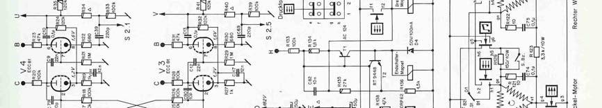
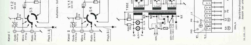
3 1 General The REVOX Series 36 has been constantly improved and kept up to date, since it was first introduced in However, the present G still bears the same basic layout and conception as did the original A recorder. Compared with the preceding models, the following major innovations have been incorporated in the REVOX G 36 recorder : Hysteresis-Synchronous Capstan motor, VU-meters for record level control and a tape-tension switch to permit the use of all reels from 7 inch up to 10 1/2 inch diameter. The G 36 model is available in both 2 and 4 track versions. Identification is made by the appropriate number being stamped on the head mounting plate, and on the upper side of the lower chassis. The recorder consists of an upper and lower chassis. These are joined at the rear by means of the back panel which carries the input and output sockets, mains voltage adjuster and fuse-holder, and at the front by means of the loudspeaker panel mountings. The upper chassis carries the tape transport mechanism and the lower chassis bears the power supply unit and the electronics. All Audio Connections are led to standard phono sockets. To interconnect the REVOX recorder with other Audio Equipment, a selection of adapter cables is available. 2 Mechanical Description The machine employs three motors. Two are identical and perform the wind and tension functions. The third motor is large and drives the capstan. It is of the pole switching variety and speed change is therefore effected electrically. The wind motors are designed to provide pulse free torque. Back tension is applied by electrical counter torque during the record and playback functions as well as during wind. The Capstan Motor is of the Hysteresis-Synchronous type, incorporating a special design feature to prevent hunting. By switching to either the 6 or 12 pole stator winding, the tape speed of 7 1/2 or 3 3/4 ips may be selected. The capstan drive, the pinch roller assembly and the headblock with the tape guides are carried on one diecast frame. This ensures accurately parallel and permanent alignment of all major transport elements. The coupling between motor and flywheel consists of special silicone-rubber strips, with the whole assembly acting as a mechanical filter. A direct slip free drive is thus achieved whilst maintaining negligible wow and flutter. The pinch roller is held against the capstan during record and replay functions with considerable pressure. This necessitates the use of a capstan bearing designed specifically to withstand considerable side pressure for long periods. The pinch roller
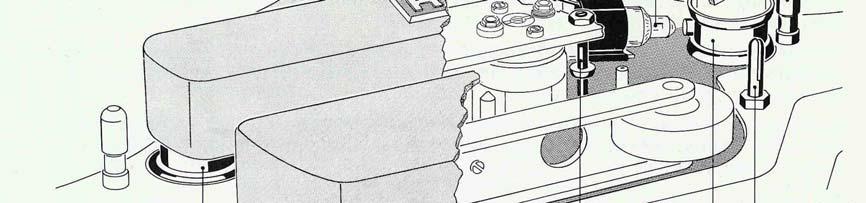
4 arm carries the shield for the playback-head and the tape-lift mechanism for the rewind function. The brakes are mechanical in nature but are electrically operated. This is achieved by the action of the brake solenoid which pulls the brakes off during all operating functions. When the stop button is pressed however, or when the current fails for any reason, the solenoid is de-energized, and the brakes automatically come on, with the higher braking force always on the trailing spindle. All functions are controlled by the push buttons. Arcing damage and noise is prevented by the use of diodes and RC networks. A sensing lever on the RH tape guide (3 in fig. 1 and 8) operates a switch (SE on schematic) which, in series with the stop button, provides a current path to a solenoid incorporated in the push button unit. This has the effect of clearing any selected function either by depressing the stop button or operation of the end of tape switch. On recorders up to serial No , the function of the end of tape switch is delayed by about two seconds to avoid tripping during the start mode. On machines with higher serial numbers (recognizable by the end-of-tape switch being made of gold-plated wire with NC contact configuration) this time delay (relais) has been utilized to supply increased operating voltage to the wind motors, thus providing the required starting torque. (Inset schematic B and diagram :6 refer.) The tape guide pins to the left and right hand side of the loading slot assist in achieving uniform tape tension due to the change in friction with varying wrap-around from large to small spooling diameters. A three digit tape counter is driven from the take-up turntable by a rubber belt. The translucent resetting knob of the counter is lit by a small pilot bulb which acts as a mains indicator. A remote control facility is provided Removal of the shorting link from the socket on the rear panel and the insertion of the correct accessory plug, lead and switch, enables the recorder to be started or stopped in either the record or playback function as selected. Operation of the remote control switch has the effect of de-energizing both the capstan and brake solenoids. ATTENTION If no remote control is used, the dummy plug must be inserted into the socket, otherwise the recorder will not start. 2.1 Mechanical checks and adjustments It is advisable to use a full and an empty 10 1/2 inch spool when carrying out adjustments. For the majority of tape transport checks, it is essential to keep the plastic top cover in position. For other mechanical adjustments the top and head covers should be removed. To remove the plastic top plate, pull off the grey control knobs, the transparent selector discs and the plastic cover over the pinch-roller arm. Further undo the mounting screws (1 in fig. 2) of both turntables, of the head cover and the mounting lugs (2 in fig. 1) of the pinch-roller cover. When reassembling, take
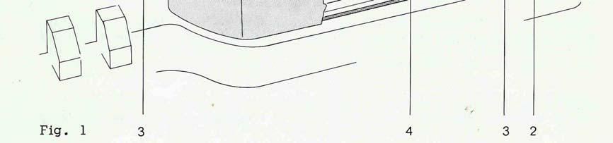
5 great care in tightening the turntable screws uniformly to prevent them from wobbling. For best results, they may have to be rotated by Tape path The tape path level is determined by the left and right hand tape guides (3 in fig. 1) and by a small guide (4) positioned between the playback head and the capstan. We do not recommend that these guides should be interfered with in any way. Adjustment to the spool carrier height can of course be made to enable the tape to be wound centrally between the spool flanges. This is brought about by sliding shimwashers of varying thickness onto the spooling motor shafts after removal of the bakelite brake drums. To pull a brake drum off the shaft, screws should be inserted into the three tapped holes (1 in fig. 2) so as to serve as handles. Care should be taken to prevent damage of the brake bands at this stage. Where a brake drum has to be removed it is recommended that the brake band be removed first Brakes The layout of the brake system is shown in fig. 2. The mounting bracket (5 in fig. 2) on the rear end (stationary) of the brake band must be held tight against the vertical pin on the chassis by sufficient tension of the leaf-spring on the bracket.


6
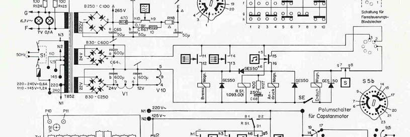
7 It is important to check that the brake band (6) is running flat on the brake lining and not biting on the upper or lower edge. Adjust alignment of brake band by slightly pivoting it in the rivets if required. Correct tension for spring 7 is obtained when grams applied as a tangent force to a 10 cm diam (spool and tape) causes the spool to move. See fig. 3. Brake tension may be altered by resetting the brake return spring (7) into any of the three holes on the end-brackets (5 and 9). The brake release solenoid must cause sufficient movement (approx. 3 mm) of the front-end bracket (9) to fully free the brake band from the lining. Depress the stop and play buttons simultaneously to energize the brake release solenoid. If the movement is incorrect, loosen the nuts (10) and re-position the solenoid. The front-end brackets of the brake bands may be bent to achieve simultaneous release of both brakes. The brakes should be kept clean and dry. Do not use any oil or grease on the linings Tape tension Back tension is applied by the combination of reverse direction torque from the feed motor and the degree of wrap around on the LH guide pin. Wear on the mechanical parts of the recorder will not alter the amount of tape tension. Any effects that could be attributed to inaccurate tape tension may be caused by: a. Faulty adjustment of the brake band b. Electrical fault in feed motor c. Electrical fault in phase shift-condenser (C 72 pos. 22 in fig. 5 and 6).
8 2.1.4 Pinch roller The pressure of the pinch roller can be measured by a gauge fixed to the pinch roller arm as close as possible to the spindle of the pinch roller (fig. 4). A constant tone tape should be played and the pinch roller withdrawn by the gauge until the note is heard to change. A reading in the region of 1.7 kg should be obtained. Adjustment to this value can usually be obtained by turning nut no 13 in fig. 5. Should this not provide the necessary amount of correction it is advisable to check the position of the solenoid no 11 in fig. 5 which will be correct when there is approx. 0.5 mm clearance at point A (fig. 5) with the solenoid energized. It is essential that the solenoid s-slug fully bottoms in the energized position and when properly adjusted, there should be no movement of the slug when lifting the pinch roller off the capstan. Correct setting can be obtained by loosening the nuts (12 in fig. 6) and moving the solenoid in the required direction End of tape switch A. Photoelectric end-of-tape-switch Recorders with serial numbers from onwards are equipped with a light sensitive auto shut-off device. It consists of a light source (Osram 3644), the photoresistor ORP 62 and a printed circuit section containing two transistors (see fig. 1). The photoconductive cell is housed in the tape guide pin on the right hand side of the recorder. It has a dark resistance of greater than 100 kω and this value drops to below 3300 Ω under illumination. The associated current amplifier energizes the push button release solenoid when light reaches the photoconductor. For normal operation of the recorder the sensing element is at its high dark resistance and both transistors are biased into cut-off. Illumination of the photo-resistor changes the bias condition on T1 thereby raising its collector current. A voltage drop develops across the solenoid winding and T2 begins to conduct. Since T2 opens a current path parallel to the photoconductor, positive feed back action sets in which causes the collector current of T1 to rise quickly into saturation.


9 To de-energize the solenoid and to restore the nonconducting condition, the supply voltage has to be interrupted. B. Mechanical end-of-tape switch. This switch and its associate operating levers must be thoroughly clean to function correctly. On G-36 recorders up to serial number , the tape sensing lever operates a snap-action switch (SE schematic A) which is closed with tape tension applied. The right position of the switch assembly is essential for correct operation to be obtained. This adjustment is carried out by slackening the fixing screws and moving the switch bodily until the snap-action switch closes when the sensing lever still protrudes by 0.5 to 1 mm from the outer diameter of the tape guide. On recorders with serial number and up, the sensing lever operates a goldplated wire contact. This switch opens when tape tension is applied (see BE in schematic Band ). Adjustment should be carried out analogue to the above specifications for the snap-action switch by bending the long wire loop. In the resting position sufficient contact pressure should be available to make the short wire loop move beyond the point of contact by approx. 0.5 mm. This is achieved by bending the contact wires while operating the tape sensing lever by hand. The end-of-tape switch and its operating lever are then properly adjusted when the switch remains open (or closed on older models) for any movement of the sensing lever inside the tape-guide post. Accidental tripping due to sticky splices etc. will thus be avoided Wow and flutter
10 Accurate and useful measurement of wow and flutter can only be made with an appropriate instrument. The recorder is calibrated using the EMT Model 420. Possible causes of flutter may well lie with the capstan, capstan motor. Wow can usually be seen as associated with the pinch roller speed and in some cases a faulty pinch roller may be the cause, and in others too much back tension or insufficient pinch roller pressure. For all wow and flutter investigations the transport mechanism must be completely clean Tape speed Tape speeds can be checked by running a marked, measured length of tape through the recorder. For a 100 sec. run 950cm would be required at 3 3/4 ips and 1905 cm at 7 1/2 ips. The difference in running time in seconds will be the speed variance as a percentage. Some variance can be expected with temperature increase but this should lie within the quoted tolerance. In very cold weather it may be noted that the recorder runs accurately at 3 3/4 ips but slows down when switched to 7 1/2 ips. This is due to drag from the cold grease in the capstan bearing, especially when new. After a short time of operation at 3 3/4 the machine should be capable of running at 7 1/2 ips. When detecting any deviations from the figures quoted, an accurate reading of the mains frequency should be taken first before investigating pinch-roller pressure, brakes etc. On a 50 cycle power line, a drop to 49.5 cycles will make the recorder run slow by 1% and this should be borne in mind when checking equipment with a specified accuracy of ± 0.3 percent. 2.2 Routine maintenance Cleaning From time to time the working parts of the recorder which come in contact with the tape should be thoroughly cleaned. Cleaning of the head faces is particularly important, especially in the case of four track heads where seemingly invisible particles can often have an adverse effect on performance. On no account must any deposits be scraped off with metallic tools. Loose tape dust, may be brushed off. For cleaning of the heads and capstan shaft, use a cotton-swab soaked with methylated spirits. (Avoid any solvents from coming into contact with the plastic parts of the recorder) Lubrication The capstan motor, the capstan bearing and the wind motors are equipped with bearings of sintered material. Each bearing has an adequate supply of lubricant which should last for the life of the bearing. Should the replacement of a motor bearing become necessary, return the unit to the nearest REVOX Repair Station. On wind motors with ball bearings (Series I and II) it is advisable to replace the ball bearings
11 once their supply of lubricant has been used up. Felt linings are to be saturated with Teresso 43 (Esso). If signs of wear become visible on the capstan shaft, the whole bearing plate complete with shaft should be replaced (see sect 2.3). Lubrication of the capstan bearings is not anticipated. However, where this can not be avoided, Teresso 43 (Esso) only must be used Servicing of solenoids When it appears that a solenoid is tending to stick or function erratically, it should be dismantled and the slug and housing thoroughly cleaned with methylated spirits. When both parts are properly clean and dry, molybdenum grease may be rubbed into the working surfaces, which must finally be wiped dry before re-assembly Servicing of push button assembly Conventional switch cleaners are not recommended for the high current spring contacts used in the REVOX, and where cleaning is necessary, the contacts should be polished clean. The interlocking bars and push-button shafts may require occasional greasing with molybdenum grease. Where a part of the assembly needs replacement, unscrew the four fixing screws, bend the pushbuttons to the right and ease the unit to a better working position. For better access to the switch assembly, the housing of the pinch roller solenoid should be removed by undoing the M 4 nuts (pos. 12 in fig. 6). 2.3 Removal of capstan assembly This may become necessary where the recorder is to be used on a mains frequency which differs from that for which the recorder was manufactured, or when replacing the capstan assembly becomes necessary. Having removed the chassis, as described in sect from the cabinet and the loudspeaker and panel, separate upper and lower chassis sections by undoing screws no 16 shown in fig. 6. Lift upper chassis without exerting excessive force, if necessary loosen the fixing screws of the selector switches (18 in fig. 6) to gain more freedom of movement. Unscrew the capstan mounting nuts (19 in fig. 6) and remove the assembly downwards and forwards out of the chassis. The fixing screws 20 in fig. 7 on the flexible coupling are to be removed through the large holes in the capstan bearing plate. The motor mounting screws (21 fig. 7) should now be removed using REVOX s special 8 mm nut driver, after which the flywheel assembly can be separated from the motor.
12
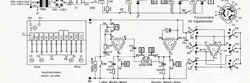
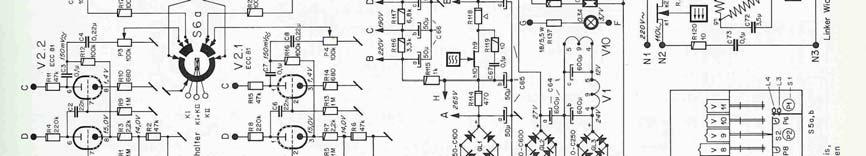
13 3 Electronic Description Access to the majority of the electronics of. the recorder can be obtained by removing the base of the recorder. The REVOX G-36 has two identical record- and replaychannels. The common bias and erase Oscillator can be switched onto either one or both channels, thus allowing stereophonic recordings, two-track sound with sound and monophonic recordings. Each channel is equipped with pre-amplifier stages to accept low-level signals from linear high-impedance sources. (Step-up transformers are required where low-impedance dynamic microphones are being used.) For monitoring the signal level, the recorder is equipped with two VU-meters and associated matching amplifiers. The built in power amplifier drives a 21 cm Ø loudspeaker and an appropriate switching arrangement permits listening to either one - or both channels, before and after tape. 3.1 Circuit checks and adjustments Measuring instruments The following items are essential: a) Ω/V DC Multi range meter b) VTVM with min. sensitivity of 3 mv full scale c) Low distortion audio generator d) Appropriate calibration tape (use REVOX Bezugsband or Bezugsband 19 DIN 45513" both of which have a frequency response corresponding to the G-36 equalization characteristic) Where a test tape with response characteristics of the recorder under examination is not available, other test tapes may be used and a set of correction figures for the individual frequencies can be obtained from the following equation: Ґ 1 and Ґ 2 designate the time constants of the equalization characteristics. Other desirable but not essential instruments include a Distortion Factor Meter and an Oscilloscope. Direct record and replay figures can only be taken when a suitable bias filter is connected between the output of the recorder and the measuring instrument. An external filter will not be necessary for those REVOX G-36 Recorders which are already equipped with the bias-suppression circuit (printed circuit with L3, L4, C 48, C76, C77, C78, R112 and R113 on amplifier chassis to the left of P1, see fig. 14 and
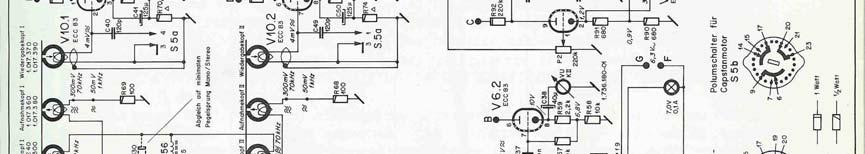
14 schematic G-36) provided that the residual RF-signal is at least 35 db below peak record level (3 % distortion). A wow- and flutter meter may be required in rare instances only De-magnetising From time to time the ferrous parts in contact with the tape may become magnetised. When this occurs, especially with head magnetisation, an increase in background noise will be evident and in serious instances, partial erasure of the tape may come about. De-magnetisation should be carried out with the appropriate instrument at frequent intervals and care should be taken at all times to ensure that magnetised tools do not come in contact with the head assembly. Permanent damage may be caused to a calibration tape by magnetised sound heads, as they will tend to partially erase the high frequencies on the tape. They may also have some adverse effects on the overall performance of the recorder Head alignment Head adjustment should only be necessary when a head requires replacement or where the setting has been interfered with. Five adjustment screws are provided I their functions are as follows: The centre screw no 22 must be undone to remove the head or to adjust the head around the vertical axis. Adjust screw no 23 at the rear of the head for height, which will be correct when the upper brass spacer of the heads is divided by the upper tape edge. Front screw no 23 should then be adjusted to bring the head face vertical with the tape. Azimuth adjustment must be carried out by turning nut no 24. Azimuth adjustment of playback head
15 Good high frequency response is possible only when the gaps of the record- and playback heads are parallel to each other. Where recordings are to be exchanged for replaying on other machines, it is furthermore essential that the head gaps are accurately aligned to an angle of 90 against the direction of tape travel. Correct adjustment is achieved by proceeding as follows: - connect VTVM to the output of one channel - run alignment tape and adjust nut 24 until a maximum reading is obtained from the VTVM (observe the instructions included with the tape) When correctly aligned, a sharp maximum will be indicated and the signal level must drop when turning nut 24 in either direction. Azimuth adjustment of record head It is essential that the playback head has been aligned as outlined above. - record 12 kc/s on good quality blank tape - with the output coupled to a VTVM nut 24 of the record head should be adjusted to give maximum output from the tape. It is of little significance which of the two channels is used for carrying out the azimuth adjustment, however, it is advisable to check the performance of the other channel also. Head adjustment by the phase check method The azimuth position of the head gap on stereo tape recorders influences not only the signal level at high frequencies, it also effects the phase relation between channels. The criterion of minimum phase deviation provides a more accurate indication of correct gap angle than the adjustment for maximum output level. To avoid a phase angle error of 90, the azimuth should first get aligned by adjusting for level maximum. A simple method for adjusting phase can be seen from the diagram fig. 9. Both channels are connected in parallel and azimuth adjustment is carried out at a test frequency of 10 kc/s to give maximum output from the tape. Where a double beam oscilloscope is available this should be employed so that traces from both channels can be observed simultaneously. Accurate azimuth alignment will permit phase to be maintained between channels at all frequencies, when correctly aligned a change of frequency will not affect the locking of phase between channels. To adjust the record head ensure that playback head is correct. Using the playback channel as a measuring reference, a signal of 10 kc/s should be recorded and the record head adjusted to give maximum playback output. Again the phase check method may be employed and this will have the effect of phasing the machine from input to output via tape at all frequencies.
16 Adjustment of four track heads This is a highly delicate operation as with a track separation of only 3/16", slight inaccuracies in head alignment cause a track overlap and lead to the very annoying dead channel cross-talk. Where a four track recorder is under examination, it is advisable to obtain the REVOX four track alignment tape. Relevant instructions are included with the tape Playback amplifier Before any tests are made on the playback section of the recorder, it is essential to ensure that the sound heads are scrupulously clean; minute particles may cause false readings by partially lifting the tape off the heads. Connect a VTVM to the cathode follower output of each channel in turn. A reference signal recorded at 32 millimaxwell per 1 mm of tape width should give an output of approximately 3 db below that specified in the technical data (refer to 5.). The frequency response section of the calibration tape is normally recorded 20 db below this level for measuring the performance characteristics of the playback channels. A response of + 2/-3 db referred to the level at 1 kc/s is acceptable. Where unsatisfactory figures are obtained it is advisable to replace the playback head as outlined in and take new readings. Should this not bring about the desired improvement, the playback pre-amplifier should be examined. Remove the earth connection of the playback head and insert a 10Ω resistor in series (fig.10.)
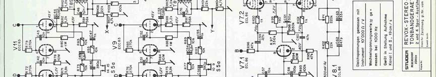
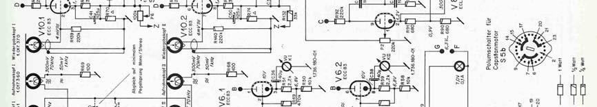
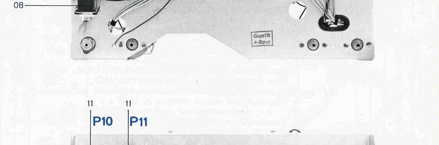
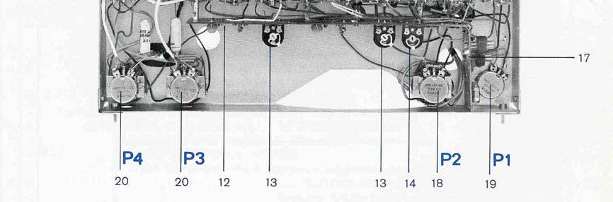
17 Connect an audio generator across the resistor and adjust output at 1 kc/s to give 70 mv at the cathode follower. The frequency response obtained should coincide with the graph shown on the back of the respective circuit diagram. Where a considerable deviance exists, checks should be made on the voltage values obtained within the circuit with special regard to the negative feedback loop which is frequency conscious Bias adjustment The procedure is described for one channel only. It is to be carried out in both channels for achieving identical performance. Connect a VTVM with a bias filter (described in ) in circuit to the output of the playback amplifier. Press the record button, leaving the record level control closed, and tune the filter for minimum indication on the VTVM. This external filter will not be required on REVOX G-36 recorders already equipped with bias-traps. It must be observed, however, that the residual bias remains below the level specified under Where a filter is not available, the overall performance can not be tested while recording, as bias leakage masks the audio signal. It will be necessary to take all readings after first recording, rewinding and then playing the tape again. Any alteration of the bias current changes the remanent tape flux and consequently effects output level, frequency response and distortion. As no two heads can be made to perform exactly alike, there is little value in measuring the bias current alone and directly. In adjusting the bias current, all of these variables are taken into consideration and the near optimum value has to be found first before the frequency response tests can be commenced with. The recommended procedure is to employ a long playing tape of compatible quality and record a 1 kc/s signal approx. 3 db below full modulation at the 3 3/4 ips tape speed. The bias should be adjusted with P 10 and P 11 (fig. 14) for channels I and II respectively, for maximum audio output.
18 The generator signal level should then be reduced by 20 db and the output level noted. After changing the frequency to 10 kc/s, bias should be adjusted to an output identical to that at 1 kc/s Measurement of overall frequency response Before any attempt is made to verify the overall response, it is advisable to see that all tests described in the preceding paragraphs have been properly observed and that the settings arrived at have been left undisturbed. A 1 kc/s signal should be recorded via the radio input socket at reference level, viz: the same output voltage should appear on the cathode follower as from the reference level of the calibration tape. The level of the signal should then be attenuated by 20 db and the overall response curve taken. It is essential for this test that the signal level is some 25 db below peak record level (3 % dist) otherwise the record preemphasis may lead to tape saturation at high frequencies thus producing false test results. Where the frequency response deviates from the specified tolerance of + 2 / - 3 db, a slight re-adjustment of the bias current may be necessary. Any variation in bias has a pronounced effect on the frequency response. If a fault is suspected to lie in the record section of the recorder, the record head should first be changed. If this does not prove to be the cause of the trouble the response curves of the amplifier should be checked with the bias oscillator valve removed. To measure the response characteristic of the record pre-emphasis use a test circuit as shown in fig. 12. The frequency response obtained should coincide with the graph shown on the back of the respective circuit diagram. Considerable deviations would indicate valve aging, or faulty components in the frequency conscious networks of the record amplifier.

19 3.1.7 VU-Meter adjustment Peak record level is defined as the level at which the signal contains 3 % of third harmonic due to tape distortion. This should correspond to an output level approx. 3 db above the reference level of the calibration tape. Where a distortion analyser is available, the alignment procedure is as follows: Record a 1 kc/s signal via the radio input with the record level control wide open and adjust generator level until a distortion factor of 3 % can be measured on the cathode follower output. A lead (higher sensitivity) of 7 db is required on the VU-Meter to compensate for its ballistic characteristic. The generator level should now be attenuated by 7 db and the trimpot on the meter amplifier adjusted for 0 VUindication on the meter. Adjustment is made with the trimpots P 8 and P 9 (fig. 14) for channel I and II respectively. Lacking a distortion analyser, a reasonably accurate alignment is possible by the following method: Note the output level produced from the reference section of the calibration tape. Record a signal of identical frequency, adjusting the input level until a level 4 db below reference level appears on the cathode follower output. Now set the trimpots of the meter-amplifiers to obtain a 0 VU reading on the meters.

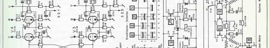
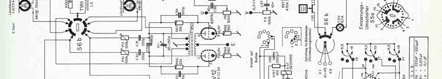
20 3.1.8 Adjustment of head shielding This may sometimes be necessary in order to keep the operating hum levels at a minimum. It should be noted also that since hum can be picked up by the electronics on the underside of the recorder, care must be taken to screen the base when the chassis is removed from its case, whether on the service bench for attention, or when built into a cabinet. To adjust the playback head shield, place two spools on the recorder with a half reel of tape wound on each and without threading the tape depress the play and stop buttons. The tape should remain stationary and the head shield may be adjusted to give the lowest reading on a milli voltmeter connected to the cathode follower output. If two meters are available it is advisable to check both channels simultaneously since an improvement in one may bring about a deterioration in the other Channel to channel crosstalk Certain physical limitation prevent one from achieving infinite crosstalk rejection. A crosstalk figure of 50 db can be reached in practice and is generally considered acceptable. It may however still be irritating in such cases where extreme level differences exist in the recordings of adjacent tracks. When checking crosstalk, one should never listen to the dead channel with a wide open monitor gain. Depending on the reserve gain available in the monitor system, the slightest amount of crosstalk will thus become audible. Crosstalk behaviour can be judged by exact measurement only. To adjust the recorder for minimum crosstalk a reference recording at full modulation (preferably music) is required on one track only. While making this test recording it is important that the bias and audio signals are inoperative on the other channel. (Channel-selector in position I or II respectively, level control of the unused channel closed). After re-winding, the recorded section is to be replayed while monitoring the unrecorded track. By adjusting trimpot P6 (fig.14) reduce any audible crosstalk until a minimum is reached. The optimum setting for P6 is found by repeating the above procedure with a recording on the other track.
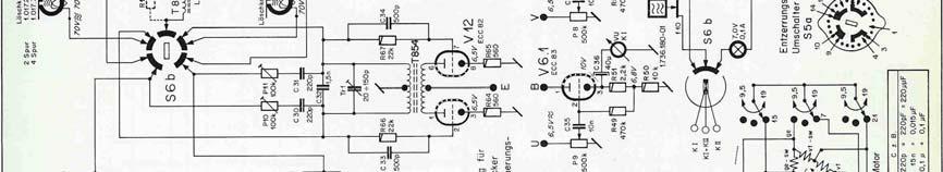
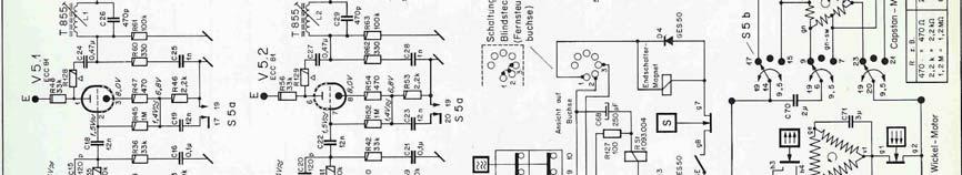
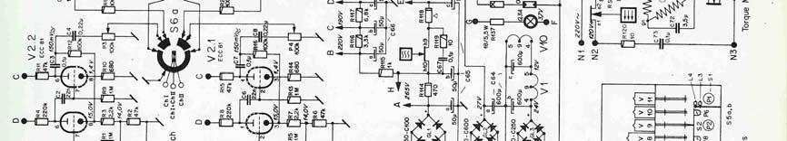
21 3.2 Tuning the bias traps The following procedure is suggested for tuning the filters L l/t 855 and L 2/T 855 (see schematic G 36, 6) on the output of the stages V 5. 1 and V 5.2 : The record circuits of both channels should be switched on by depressing the buttons record and channels I + II (stereo), causing the oscillator (V 12) to generate 70 kc/s. The record level controls P 3 and P 4 remain closed. A VTVM or oscilloscope with a sensitivity that assures useful deflection at 1 mv 100 kc/s should be connected to pin 1 on the socket of V 5 (Plate, Channel I) and the slug of L 1 (Fig. 14) is to be tuned for a minimum reading. After connecting the VTVM or oscilloscope to pin 6 of the same socket (Plate, Channel II) the slug of L 2 should get tuned analogue to the above. Tuning of the bias filters on the cathode follower outputs V 9 and V 11 (not obtained in the early version of the G-36) : The record circuits should be turned on as described above. With the VTVM or oscilloscope connected to the cathode follower outputs A - K I and A - K II the slugs of L 3 and L 4 (Fig. 14) respectively should get tuned for minimum indication on the test equipment.
22 4 Troubleshooting 4.1 Mechanical troubleshooting Trouble Cause How to repair Capstan motor does not run at either speed Noisy capstan Tape speed too low Capstan runs at 3 3/4 but not at 7 1/2 ips Pinch roller arm does not operate Brakes do not release Push-button will not remain in pressed position End of tape switch does not operate Speed switch in mid-position Speed switch defective Jamming motor Jamming capstan bearing Felt of the lower bearing damaged Loose flywheel Damaged capstan-bearing Damaged motor bearing Open-circuit motor-winding Faulty motor condenser Jamming capstan Recorder too cold and drag from new bearing or grease too great Dirty solenoid Dirty contacts in the pushbutton assembly Dummy-plug of remote control removed Dirty brake-solenoid Dirty contacts in the pushbutton assembly Dummy plug removed End of tape switch does not operate Incorrectly threaded tape Dirty solenoid End of tape switch contacts maladjusted Light bulb defective. Light-port in the right-hand guide pin blocked with tape dust. Switch to 3 3/4 or 7 1/2 speed Replace wafer Clean and lubricate bearings (2.2.2.) Replace capstan assembly Replace felt and lubricate with SAE 20 oil Tighten fastening nut Replace capstan assembly Replace motor Replace capstan motor Replace motor condenser Replace capstan assembly Run at 3 3/4 for a few minutes. Recorder will then pick up to 7 1/2 ips Clean and adjust solenoid (2.2.3.) Clean and adjust solenoid (2.2.4.) Connect pin 1, 2 and 3 of the remote control socket Clean and adjust solenoid (2.2.3.) Clean and adjust contacts (2.2.4.) Connect pin 1, 2 and 3 of the remote control socket Adjust (2.1.5.) Thread the tape as explained in the instruction manual Clean and adjust (2.2.3.) Adjust (2.1.5.) Replace light bulb Osram 3644 Carefully clean the opening.
23 Wow and flutter Fast rewind or forward too slow Damaged or dirty pinch roller, pinch roller pressure insufficient, left side brake maladjusted, jammed turntable motor. Brake maladjusted Dirty brake solenoid Open-circuit winding in the Turn-table-motor Defective motor-condenser Replace pinch roller. Clean capstan and pinch roller, adjust pinch roller arm (2.1.4.) adjust brake (2.1.2.) clean and lubricate motor-bearings Adjust brakes (2.1.2.) Clean solenoid (2.2.3.) Replace turntable-motor Replace motor-condenser 4.2 Electronic troubleshooting Trouble Cause How to repair Playback hum Playback hiss Bad treble response Absence of recording or insufficient recording Insufficient erasure No indication on the VU-meter Short circuit in the power supply Disconnection in the playback head Front shielding of the playback head out of adjustment Faulty tube in the playback amplifier Magnetised playback head Dirty head Heads out of alignment Worn out heads Tape wrongly threaded Bias incorrect Dirty recording-head Defective recording-head Dirty contact of recording push-button Incorrect bias adjustment Defective bias-oscillator Erase head soiled Erase head defective Bias-oscillator defective VU- meter defective Indicator amplifier valve defective Maladjusted potentiometer Speed switch of capstan-motor burned out Replace playback head Adjust front shielding (3.1.8.) Replace tube De-magnetising the head (3.1.2.) Clean the heads (2.2.1.) Adjust the heads (3.1.3.) Replace heads Thread tape as explained in the instruction manual Adjust bias (3.1.6.) Clean the head Replace the head Clean and adjust contact Adjust bias (3.1.6.) Check bias-oscillator tube, coil and erase head Clean heads (2.2.1.) Replace erase head Check bias-oscillator tube, coil and erase head Replace VU-meter Replace valve Adjust level control (3.1.7.) Replace wafer
24 5 Technical Data Tape Speed: 3 ¾ and 7 ½ ips 6/12 pole Hysteresis Synchronous capstan motor, direct drive Wow and flutter: ± 0.1%, at 7 ½ ips peak reading ± 0.15%, at 3 ¾ ips weighted (DIN 45507) Tape speed deviation: 0.3%, from nominal Max. spool size: 10 ½ (265mm) Rewind time: 120s for 3300ft of tape (10 ½ reels) Frequency Response: c/s at 7 ½ ips +2/-3 db Equalization: USA / 60 cps: c/s at 3 3/4 ips +2/-3 db In accordance with IEC standards 70 µs/3180 µs at 7 ½ ips 140 µs/3180 µs at 3 ¾ ips In accordance with NAB standards 50 µs/3180 µs at 7 ½ ips 940 µs/3180 µs at 3 ¾ ips Harmonic distortion: 3% at peak recording level (overall) Signal to noise ration unweighted: 2-track recorder 55db peak recording level at 4-track recorder 52 db 3% harmonic distortion Dynamic range: 2-track recorder: 55db at 7 ½ ips 53db at 3 ¾ ips 4-track recorder: 52db at 7 ½ ips 50db at 3 ¾ ips Crosstalk: Mono 60db Stereo 40db Oscillator-bias 70 kc/s, push-pull oscillator frequency: Inputs per channel: 1. Microphone 3mV, Ri = 0.5 MΩ max. 600mV 2. Radio / Tuner 50mV, Ri = 1 MΩ max. 10V 3. Diode / Aux. 3-50mV, Ri = 47 kω adjustable Outputs: Tube complement: 2 High Impedence outputs, Eout 0.7V (2-track) Load resistance not less Eout 0.5V (4-track) than 0.1 MΩ 1 loudspeaker output 5Ω, 6W rms. Push-pull power amplifier, internal speaker may be switched off. 4xECC81, 1xECC82, 5xECC83, 2xECL86, 2 Transistors, 5 silicon diodes, 3 selenium rectifiers Power line voltage: 110, 125, 145, 220 and 240 V, 50 cps USA 117 V / 60 cps Power Requirements: Approx. 120W Fuses: for V : 0.6 A 5 x 20 mm for V : 1.2 A slow blow USA 117 V : 1.2 A slow blow type 3 AG Weight: Approx 45 lbs
25 Case dimensions: 19 x 13 ½ x 12 Chassis dimensions: 21 ¾ x 15 ½ x 10 ¾ (with 10 ½ reels) Colour: grey All data are valid for the 2-track as well as for the 4-track recorder unless specified otherwise.


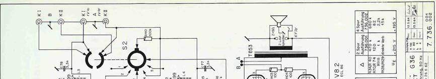
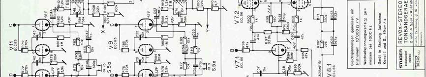
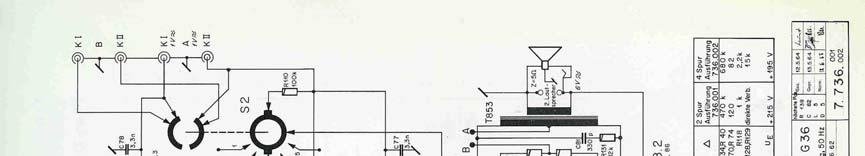
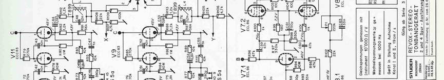
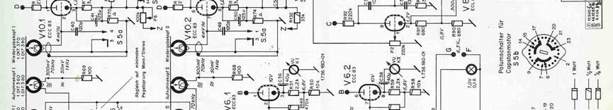
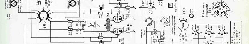
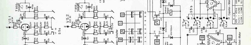
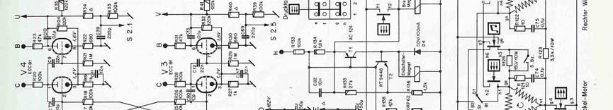
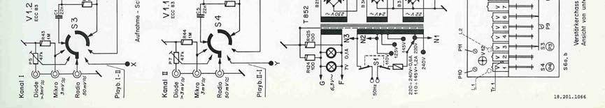
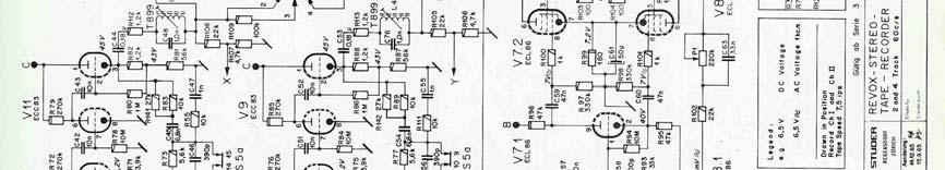
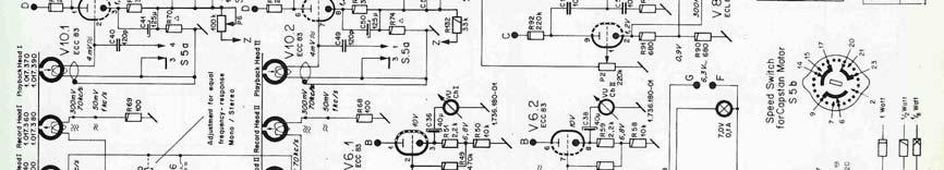
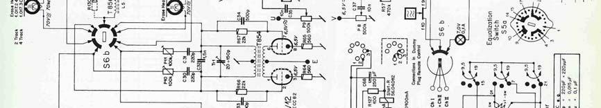
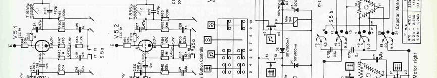
26 6 Circuit Diagram

27


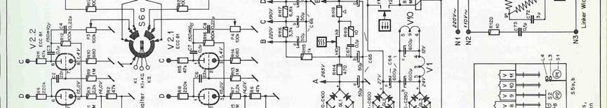

28


29
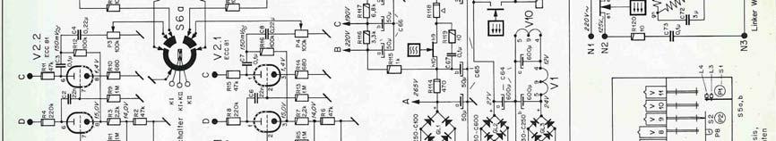
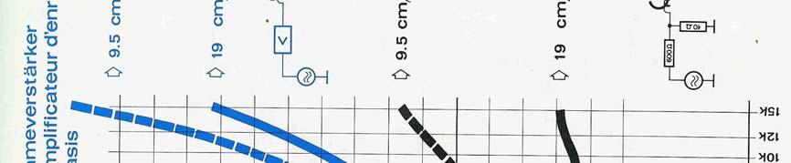
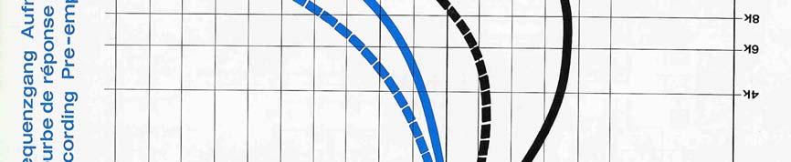
30 Modifications effective from serial number: (Motor-control circuit) onwards (Transmission response of record amplifier) Motor - control circuit Changes in the circuit of the spooling motors were effected in order to improve the performance during the start-mode under extreme ratios of the supply and feed loads. The relay R. St. mentioned on page 3 which operates with a delayed release time, now supplies the higher voltage during the start-mode to the right hand spooling motor only. Perfect starts are thus assured even with small tape roll diameters on both sides. In situations where the recorder has to be started with large tape roll diameters on the right hand side, performance is improved by the fact that the tension remains -constant on the left hand motor during the operating time of the R.St. relay. The relay R.St. is being actuated by a current pulse. It remains de-energised during all other stages of operation. The condenser C 68 (250 mf) which receives its charge from the 24 Volt supply, discharges through the R.St. relay when depressing the play-button and the relay gets energised for 0,3 sec. approx., thereby feeding a higher supply voltage to the right hand spooling motor for that period of time. Transmission response of record amplifier As can be seen from figure 13, page 14, there is a considerable rise in the high frequency response of the record amplifier. This response characteristic is necessitated by the standardised replay equalisation, as well as by the type of tape emulsion utilised for recording. The frequency response displays a peak around 30 kc on machines up to the above mentioned serial number. In conjunction with the extremely wide response characteristic of the record and replay amplifiers, this could cause interferences due to overmodulation when recording programs derived from carrier distribution systems with too high a residual RF component after demodulation. Furthermore, it was difficult to obtain precise readings with wow and flutter meters employing square wave test signals. With the insertion of an inverse feedback loop (V3 - C80, V4 - C79, respectively 10 mmf each) plus a reduction in value of the cathode by-pass capacitor (V3 - C17, V4-Cll respectively, reduced from 0,015 to 0,012mf) The response peak could now be lowered to 23 kc approx. The frequency response curve remains unaltered in the portion of the audio band which is required for sound recording. The following values of attenuation are thus obtained: 7 1/2 ips 3 3/4 ips 30kc - 8 db -11 db 38 kc -12 db - 13 db which greatly eliminates the possibility of generating beat signals from ultra sonic frequencies. Where stereo broadcasts are to be recorded, use of the REVOXmultiplex filter will be essential, particularly when operating at the tape speed of 3 3/4 ips.
31 REVOX G 36 recorders not containing these modifications can easily be adapted to the new response characteristic by replacing and/or adding the above mentioned components.


32

33

34
35


36

37

38
39 7 SPARE PARTS LIST - ISSUE IV This Issue of the Spare Parts List has been augmented in all sections and exploded views are included for the more complicated sub-assemblies. The tabulations are divided into the following columns: INDEX ORDER NUMBER PART DESCRIPTION SERIES QUANTITY INDEX III Index numbers are identical with the tracer numbers shown in the drawings and photographs. This number must be used when ordering spare parts. In case of inexact part description due to translation errors the german version shall be the determinant. When ordering plastic parts with the same order number, but of slightly differing colour, add colour code number. The three columns indicate in which series a particular part is used. Parts which are not directly interchangeable between Series are marked by the letter (x) in parentheses. They have to be replaced by complete sub-assemblies. Indicates the number of identical parts within the assembly. Cross index with Parts List Issue III which is now cancelled. Index III must not be used any more when ordering parts. ALL ORDERS SHOULD STATE ORDER NUMBER AND SHORT PART DESCRIPTION.
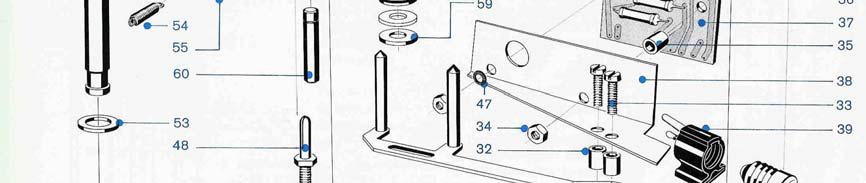
40 INDEX ORDER N PART DESCRIPTION SERIES Qu Ind III I II III Carrying Case Case Bottom Complete x x x Case Bottom x x x Rubber Washer (Case Bottom Mount) x x x Machine Screw (Case Bottom Mount) x x x Washer for Case Bottom Mount x x x Case top Complete x x x Latch Case Top x x x Case Middle Section Complete x x x Rear Panel Cover Snap-fit x Rear Panel Cover, Hinged, including Frame x x Case Feet x x x Chassis Mounting Bracket x x x Mounting Bracket Screw x x x Loudspeaker Lattice (Trapezoid) x Loudspeaker Lattice (Rectangular) x x Carrying Handle Mounting Bracket x x x Rivet, Tubular x x x Washer x x x Carrying Handle x x x Machine Screw M 4x8 (Chassis to Bracket) x x x Top Plate Top Plate Complete x x 7021 Top Plate of Series I to be replaced with Top Plate x and Counter Machine Screw M 3x12, Oval Head, for Mounting of x x x Top Plate Plastic Cover for Pressure Roller x x Plastic Cover for Pressure Roller x Plastic Head Cover (without Name Plate) x x Machine Screw M 3x10, Oval Head x x Revox Name Plate x x x Plastic Head Cover (with Name Plate) x Grey Plastic Knob (transparent) x x x Felt Washer x x x Grey Plastic Knob Colour 1035 x x Grey Plastic Knob Colour 6760 x Push Button Red x x x Push Button Black x x Push Button Grey x Escutcheon Plate x x x Escutcheon Plate, Push Buttons x x x VU Meter x x x VU Meter Mounting Board (Paxolin) x x x Cover, VU Meter x x x Tubular Spacer x x x Pilot Lamp 7V / 0.1 A x x x Lampsocket Complete (without lamp) x x x
 x x x 4 7142 01 1.736.578-02 Push Button Grey Colour 1035 x x 5 7143 01 1.736.578-02 Push Button Grey Colour 6760 x 5 7144 02 25.16.")


41 INDEX ORDER N PART DESCRIPTION SERIES Qu Ind III I II III A Push Button Assembly Push Button Assembly Complete Colour 1035 x x Push Button Assembly Complete Colour 6760 x Self Tapping Screw (Push Button Mounting) x x x Push Button Grey Colour 1035 x x Push Button Grey Colour 6760 x Push Button Retaining Pin x x x Diode, Noise Suppression 50V / 100mA x x x (Diode on Relay - socket Series III) Switching Diode 50V / 500mA x Contact, Stationary x Contact, Stationary x x Paxolin Switch Lever x x x Moving H Contact x x x Solenoid, Push Button Release x x x Slug, For all Solenoid x x x Leaf Spring, Locking Bar x x x Contact Spring x x x Push Button Spring x x x Speed Selector Switch Complete x x x Speed Selector Switch Complete 7.5/15 ips x 1


42 Motor Wafer x x Motor Wafer x Equalization Wafer x x x Recording Channel Selector Complete x x x Oscillator Wafer x x x Amplifier Wafer x x x
43 INDEX ORDER N PART DESCRIPTION SERIES Qu Ind III I II III B Capstan Drive Assembly Capstan Drive Assembly Without Head Support x x x 1 50Hz Capstan Drive Assembly Without Head Support x x x 1 60Hz Capstan Drive Assembly Without Head Support x 1 7.5/15 ips 50 Hz 4/8 Pol Capstan Drive Assembly Without Head Support 7.5/15 ips 50 Hz 6/12 Pol x Hexagon Nut M4 x x x Threaded Mounting Stud x x x Capstan Bearing Plate (see section C) Coupling Strip for Screw Mounting (for motor with 2 coupling pins) x x x Machine screw for above (M 3x8) x x x Coupling Strip, Push-On type (for motor with 4 coupling pins) x Flywheel Complete (for Motor with 2 Coupling Pins) x x x Flywheel Complete x 1 (for Motor with 4 Coupling Pins) Washer x x x Spring Washer x x x Hexagon Nut x x x Coupling Pin (for Motor with 2 Coupling Pins) x x x Coupling Pin (for Motor with 4 Coupling Pins) x 4 2 different types of capstan motors are used in the G36 Old version: 2 coupling pins and strips with screw mounting. New version: 4 coupling pins and strips with push-on mounting. The coupling pins have to be ordered separately Capstan Motor 50 Hz OLD x x x Capstan Motor 50 Hz NEW x Capstan Motor 60 Hz OLD x x x Capstan Motor 60 Hz NEW x Capstan Motor 50 Hz 7.5/15 ips 4/8 pol x Capstan Motor 50 Hz 7.5/15 ips 6/12 pol x Motor Housing x x x Machine Screw M 4x8 x x x

44 INDEX ORDER N PART DESCRIPTION SERIES Qu Ind III I II III C Capstan Bearing Plate with Shaft Capstan Bearing Plate Complete with Shaft 50 Hz x x x Capstan Bearing Plate Complete with Shaft 60 Hz x x x Capstan Shaft 50 Hz x x x Capstan Shaft 60 Hz x x Capstan Shaft 50 Hz 7.5 / 15 ips 4/8 pol x Capstan Shaft 50 Hz 7.5 / 15 ips 6/12 pol x Felt Ring (Lubrication) x x x Grease Cup x x x Capstan Bearing Plate without shaft x x x Thrust Washer, Top x x x Felt Washer x x Low friction Washer, Plastic Coated x 1 when replacing felt washer ( ) with low friction washer ( ) the steel shim 1mm ( ) has to be interchanged with the steel shim of 0.5 mm thickness Steel Shim 1 mm x x Spring Washer EL9 x 1 Spring Washer x x True arc ring 24 x x x 1


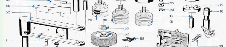
45 INDEX ORDER N PART DESCRIPTION SERIES Qu Ind III I II III D Head Support Block
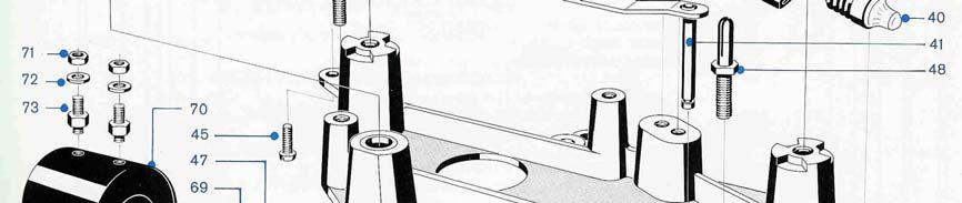
46 Head Support Block Complete with 2-track Heads x x x without pinch-roller arm Head Support Block Complete with 4-track Heads x x x without pinch-roller arm Head Support Block Complete with 2-track Heads 7.5/15 ips 6/12 pol Head Mounting Plate, bare x x x Head Mounting Plate, Complete, without Heads x x x Head Support Block Bare (Including 7.5/15 ips 4/8 x x x 1 pol) Head Support Block Bare 7.5/15 ips 6/12 pol x Slotted Nut (Head Mounting) x x x Screw (Vertical Adjuster) x x x Slotted Nut (Vertical Adjuster) x x x Hexagon Nut M 2.6 x x x Washer x x x Spring Washer 3.2/8 x x x Spacer, Azimuth Adjuster x x x Head Block Fixing Screw (Screw On Head Cover) x x Head Block Fixing Screw (Plug-In Head Cover) x Tubular Spacer x x x Tape Guide Cup x x x Tape Guide Centre Piece, Left x x Tape Guide Centre Piece, Left x Tape Guide Centre Piece, Right (Mech. And Switch) x x Tape Guide Centre Piece, Right (Opt. And Switch) x Tape Guide Post, Left (Ser I + II also right) x x x Tape Guide Post, Right (Opt. And Switch) x Photo resistor ORP 62 x Threaded bushing x x x Lock Washer M4 x x x Machine Screw M 4x10 x x x Hexagon Nut M 3 x x x Pin x x x Guide Washer x x x Spacer x x x Hexagon Nut M 2 x x x Tape Guide Pin Complete x x x Head Mounting Dise Complete x x x Sheilding Can x x x Washer x x x Erase Head 2-Track (check serial n of recorder) x x x Erase Head 4-Track (check serial n of recorder) x x x Erase Head 2-Track (from n up and for n x & ) Erase Head 4-Track (from n up and for n x & ) Recording Head 2-track x x x Recording Head 4-track x x x Playback Head 2-track x x x Playback Head 4-track x x x Tubular Spacer x Machine Screw M 3x10 x Hexagon Nut M 3 x Tubular Spacer x Machine Screw M 3x12 x Auto-stop Amplifier Complete x
47 Transistor AC 124 x Transistor RT 9448 x Mounting Bracket x Lamp Socket E 10 x Minature Lamp Osram (3.7V / 0.3A with Lens) x Tape Lift Lever OLD x x Retaining Ring for above x x Tape Lift Lever NEW x Retaining Ring x x x Washer x Tubular Spacer x Machine Screw M 3x10 x x x Lock Washer M 3 x x x Mounting Lug (Pinch Roller Cover) x x x Threaded Plate x x x Face Shield Complete x x x Machine Screw M 2x5 x x x Pinch Roller Arm x x x Paxalin Washer x x x Return Spring x x x Retaining Ring x x x Teflon Spacer x x x Pinch Roller x x x Clip, Pinch Roller Complete x x x Spacer x x x Pinch Roller Spindle x x x Lever x x x Allenscrew M 5x6 x x x Compression Ring x x x Adjusting Nut x x x Hexagon Nut M 4 x x x Spindle x x x Bracket x x x Special Screw x x x Slug, for all Solenoids x x x Pinch Roller Solenoid x x x ( Push Button Release Solenoid) x x x ( Brake Solenoid) x x x Hexagon Nut M 4 For Pinch Roller and Brake x x x 4 Solenoid Washer For Pinch Roller and Brake Solenoid x x x Threaded Stud For Pinch Roller and Brake Solenoid x x x * Mechanical End of Tape Switch End of Tape Switch Complete N Contact Spring N End of Tape Switch N incl. Series II Machine Screw M 3x6 x x Tape Pressure Switch Complete with Mounting x x Bracket Lever, End of Tape Switch x x


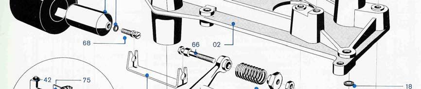
48 INDEX ORDER N PART DESCRIPTION SERIES Qu Ind III I II III E Brakes Spooling Motors Turntable with Shaft Section x x x Machine Screw Oval Head M 3x8 x x x Shaft Section, Upper x x x Shaft Screw x x x Reel Lock Spring x x x Brake Drum Complete x Brake Drum Complete x x Brake Lining, Available by the Metre Mounting Spring, Brake Drum x x x Brake Band, Complete with Mounting Brackets x x x Brake Tension Spring x x x Retaining Ring x x x Self-tapping Screw 4x1/4 x x x Angle Bracket x x x Brake Release Arm x x x Counter Pulley x x x Shim Washer Left & Right 0.5 mm x x x Shim Washer 0.2 mm for height Adjustment of
49 Brake Drum Tubular Spacer Right x x x Tubular Spacer Left x x x Machine Screw M 4x8 x x x Mounting Bracket, Spooling Motor x x Spooling Motor 50 Hz x Spooling Motor 50 Hz x x Spooling Motor 60 Hz x x Motor Deck Complete x x Motor Deck Complete 7.5 / 15 ips x Brake Solenoid x x x Mounting Stud for Brake Solenoid see Index B Motor Condenser 2 µf Capstan Motor 50 Hz x x Motor Condenser µf Capstan Motor 50 Hz x Motor Condenser 3 µf Spooling Motor 50 Hz x x Motor Condenser 3.5 µf Spooling Motor 50 Hz x Turns Counter x Turns Counter Colour 1035 x Turns Counter Colour 6760 x Lens Counter x x Belt for Counter x Belt for Counter x x Tape Tension Switch x x x Tape Tension Switch Lever Colour 685 x x Tape Tension Switch Lever Colour 6760 x Relay Serial N Relay Serial N Relay Serial N Incl Series II Relay Serial N and up x

50
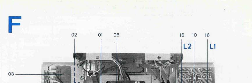
51 INDEX ORDER N PART DESCRIPTION SERIES Qu Ind III I II III F Amplifier - Chassis Electrolyte Condensor 3 x 50 µf 350 V x x x Electrolyte Condensor 3 x 600 µf 35 V x x x Rectifier B 30 C 1000 / 600 Sealed x x x Rectifier B 250 C 100 x Rectifier B 250 C 100 Sealed x x Rectifier B 30 C 250 x x x Mains Transformer 50 Hz x x x Mains Transformer 60 Hz x x Mains Transformer Semko x x x Output Transformer x x x Bias Oscillator Complete (less valve) x x x Oscillator Coil T 854, Less Ferrite Housing x x x Check serial n of recorder: Bias Oscillator Complete 2-Track N and x 1 above and for & Bias Oscillator Complete 4-Track N and x 1 above and for & Bias Oscillator Complete T 854 N and above x 1 and for & Oscillator Coil Housing x x x Potentiometer 100k (P 10 + P 11) Bias Adjust x x x Trimmer Condenser pf, Bias Oscillator x x x Equaliser Panel (Printed Circuit Complete) Incl. x x x Trimm-pot meter and VU-meter amplifier 2-Track 50 Hz Equaliser Panel Complete 2-Track 60Hz NAB x x x Equaliser Panel Complete 4-Track 50Hz x x x Equaliser Panel Complete 4-Track 60Hz NAB x x x Equaliser Panel Complete 2-Track 7.5/15 ips 50Hz x x x Trimm-Pot Meter 500K VU-Meter Amplifier x x x Trimm-Pot Meter 100K, Cross-talk Comp. x Coil, Dummy Head Load T856 x x x Coil, Dummy Head Load T Track N x 1 and above and for & Coil, Dummy Head Load T Track N x 1 and above and for & Bias Rejection Filter, Record T 855 x x x Bias Rejection Filter, Playback T 899 Complete with x x x Two Coils (L3 + L4) Switch Wafer (S2) Monitor Selector x x x Potentiometer (P2) 220 K Monitor Volume x x x Switch Positioner, Monitor Selector x x x Potentiometer (P1) 220 K, Bass Control x x x Switch Wafer (S3, S4) Input Selector x x x Switch Positioner, Input Selector (S3, S4) x x x Potentiometer (P3, P4) 100 K Record Level x x x Mains Switch x x x Outer Shaft Extension Complete for Mains Switch x x x Outer Shaft Extension Complete for Input Selector x x x Ch I Outer Shaft Extension Complete for Input Selector Ch II x x x


52 Outer Shaft Extension Complete Monitor Selector x x x Inner Shaft Extension, Long x x x Inner Shaft Extension, Short x x x Loudspeaker AD 3800 M x x x Loudspeaker Complete with Baffle x x x Washer, Speaker Baffle x x x Self Tapping Screw x x x Hexagon Nut M 4 x x x Self Tapping Screw, Upper to Lower Chassis x x x G Speed Nut for above x x x Double Phono Socket x x x Remote Control Socket x x x Potentiometer 47 K for Diode Input x x x Mains Voltage Selector x x x Voltage Selector Knob x x x Fuse 0.63 A / 220 V x x x Fuse 1.25 A / 110 V x x x Remote Control, Dummy Plug x x x Loudspeaker Socket (with Switch) x x x 1 Tools and Service Aids Calibration Tape (Full Track Recording) per IEC x x x Recommendation with 4 track alignment section Double Screw driver 337 R x x x Spring Scale 0.5 kg x x x Spring Scale 5 kg x x x Nut Driver 8 mm spec for Capstan Assembly x Head Demagnetiser x x x
SonoruS Audio. ATR10 Analog Tape Reproducer. Operating Manual
 SonoruS Audio ATR10 Analog Tape Reproducer Operating Manual 1 OPERATING INSTRUCTIONS FOR THE SonoruS ATR10 IMPORTANT NOTES Protect your tape deck from excessive heat and humidity. Install it in a manner
INSTRUCTIONS FOR USE Pro-Ject RPM 1 Genie
 INSTRUCTIONS FOR USE Pro-Ject RPM 1 Genie 8 9 4 1 11 2 6 16 5 3 7 10 Controls, features and connections 1/11 Motor unit with stepped drive pulley and power switch 2 Drive belt * 3 Platter 4 Tonearm counterweight
COHERENCE ONE PREAMPLIFIER
 COHERENCE ONE PREAMPLIFIER OWNER S MANUAL TABLE OF CONTENTS Introduction Features Unpacking Instructions Installation Phono Cartridge Loading Basic Troubleshooting Technical Specifications Introduction
INSTRUCTIONS FOR USE Pro-Ject Essential Basic
 INSTRUCTIONS FOR USE Pro-Ject Essential Basic 12 14 14 10 44 22 4 9 1 2 77 8 66 7 3 66 6 5 11 14 13 Controls, features and connections 1 Power switch 2/22 Stepped drive pulley and drive belt * 3 Platter
MclNTOSH MODEL C-4 and C-4P
 INSTRUCTION MANUAL MclNTOSH MODEL C-4 and C-4P AUDIO COMPENSATORS McINTOSH LABORATORY, INC. 320 Water St. Binghamton, N. Y. U.S.A. - 1 - INSTRUCTION MANUAL McINTOSH MODEL C-4 and C-4P AUDIO COMPENSATORS
Location and function of controls
 Location and function of controls 1. Motor Control Selector 9. DC INPUT SOCKET 2. PAUSE Key 10. DIN Socket 3. STOP/EJECT Key 11. RECORD Indicator (Yellow) 4. FAST FORWARD/CUE Key 12. DATA Indicator (Green)
OPERATING INSTRUCTIONS FOR SYLVANIA. Type I08 Cathode-Ray Oscilloscope. Sylvania Electric Products Inc. Industrial Apparatus. Emporium, Pennsylvania
 OPERATING INSTRUCTIONS FOR SYLVANIA Type I08 Cathode-Ray Oscilloscope Sylvania Electric Products Inc. Industrial Apparatus Plant Emporium, Pennsylvania OPERATING INSTRUCTIONS FOR Sylvania Type 08 Cathode-Ray
THE TEAC A3440 By Les Carpenter G4CNH
 THE TEAC A3440 By Les Carpenter G4CNH DISCLAIMER This document has been composed purely by trying to analyse the original Teac A3440 circuit diagrams. No physical electrical measurements have been made
Introduction Front Panel Functions Rear Panel Functions Precautions Placement & Ventilation... 5
 Contents Introduction... 2 Front Panel Functions... 3 Rear Panel Functions... 3 Precautions... 5 Placement & Ventilation... 5 Installation & Operation... 5 Care & Maintenance... 7 Troubleshooting... 8
CONTROLS AND CONNECTIONS - figs. 1 & 2
 Scanned, ocr ed and converted to PDF by HansO, 2001 CONTROLS AND CONNECTIONS - figs. 1 & 2 (1) tape counter with zero reset button (2) SAVE indicator - lights up during data saving (3)DATA FLOW indicator
SIMET AVIKO D INSTRUCTION MANUAL SORTING Solutions, Ltd.
 SIMET AVIKO D INSTRUCTION MANUAL 1870 SORTING Solutions, Ltd. 1. TABLE OF CONTENTS 1. TABLE OF CONTENTS...1 2. INTRODUCTION...2 2.1. Application...2 2.2. Operating Conditions...2 2.3. Electro - Optical
Rebis Audio Ltd. RA226 Digital Sampler User Guide
 Rebis Audio Ltd. RA226 Digital Sampler User Guide CONTENTS Page Caution 2 Powering Up 2 Controls 3, 4 Detailed Description Input Level Set 5 Recording 5 Sampling 5 Multiple Samples 6 Editing 6 Playback
Instruction manual. KUZMA 4POINT 14 inch TONEARM Serial Number:
 Instruction manual KUZMA 4POINT 14 inch TONEARM Serial Number:.. 2016-09 1 KUZMA LTD INSTRUCTION MANUAL FOR 4POINT 14 tonearm The 4POINT 14 tonearm is a very precisely engineered piece of equipment, however,
Ampex AG-440 Cosmetic Evolution
 Page 1 of 8 Ampex AG-440 Cosmetic Evolution Ampex Corporation introduced the AG-440 reel to reel studio mastering deck in 1967. The model went through 3 generations and was in production into the mid 1980's.
DATA RECORDER. Operating Instructions
 DATA RECORDER Operating Instructions Within this publication the term 'BBC' is used as an abbreviation for 'British Broadcasting Corporation'. Copyright ACORN Computers Limited 1984 Neither the whole or
110LP MOON Series. Phono Preamplifier. Owner s Manual
 Phono Preamplifier Owner s Manual Owner s Manual I Table of Contents Introduction 4 Unpacking 5 Installation & Placement 5 Circuit Board Layout s 6 Internal Adjustments 7 Rear Panel Connections 8 Operating
Flat-Bed Module Recorders
 Flat-Bed Module Recorders Model No. 08376-50 08376-55 08376-60 0115-0192 4/28/00 Table of Contents Introduction...3 Power Requirements...3 Chart Paper Installation...3 Pen Installation...5 Grounding...5
PREAMPLIFIER INTRODUCTION INSTRUCTIONS FOR USE. Thank you for purchasing the Musical Fidelity A3 CR remote control preamplifier.
 INTRODUCTION A3 CR PREAMPLIFIER INSTRUCTIONS FOR USE Thank you for purchasing the Musical Fidelity A3 CR remote control preamplifier. Used properly and carefully, it should give you many years of outstanding
Orbit TM DIGITAL SHAKERS
 Orbit TM DIGITAL SHAKERS INSTRUCTION MANUAL Models P2, P4, M60, 300, 1000, 1900 Labnet International PO Box 841 Woodbridge, NJ 07095 Phone: 732 417-0700 Fax: 732 417-1750 email: labnet@labnetlink.com 2
T L Audio. User Manual C1 VALVE COMPRESSOR. Tony Larking Professional Sales Limited, Letchworth, England.
 T L Audio User Manual C1 VALVE COMPRESSOR Tony Larking Professional Sales Limited, Letchworth, England. Tel: 01462 490600. International +44 1462 490600. Fax: 01462 490700. International +44 1462 490700.
Modifying the RW1127 and similar TWTs for 24GHz
 Modifying the RW1127 and similar TWTs for 24GHz Some notes by Brian G4NNS updated after the EME conference. Issue 1.04 During a visit from Johannes DF1OI he explained how Ulli DK3UC had modified Siemens
Guía del usuario Español ( 7 10 ) Guide d utilisation Français ( ) Guida per l uso Italiano ( ) Benutzerhandbuch Deutsch ( )
 Guide d utilisation Français ( ) Guida per l uso Italiano ( ) Benutzerhandbuch Deutsch ( )") User Guide English ( 3 6 ) Guía del usuario Español ( 7 10 ) Guide d utilisation Français ( 11 14 ) Guida per l uso Italiano ( 15 18 ) Benutzerhandbuch Deutsch ( 19 22 ) Appendix English ( 23 ) User Guide
User Guide English ( 3 6 ) Guía del usuario Español ( 7 10 ) Guide d utilisation Français ( 11 14 ) Guida per l uso Italiano ( 15 18 ) Benutzerhandbuch Deutsch ( 19 22 ) Appendix English ( 23 ) User Guide
Solid-State Digital Timer
 Solid-State Digital Timer 1/16 DIN, Digital-Set Timer with 0.1 Second to 9,990 Hours Range 8 field-selectable operation modes Universal AC/DC supply voltage timers available Operations include ON-delay,
INTEGRATED AMPLIFIER INSTRUCTIONS FOR USE
 INTEGRATED AMPLIFIER INSTRUCTIONS FOR USE Thank you for purchasing the Musical Fidelity Amplifier. Used properly and carefully, it should give you many years of outstanding musical reproduction. The is
INSTRUCTIONS FOR USE Pro-Ject 1 Xpression III Comfort
 INSTRUCTIONS FOR USE Pro-Ject 1 Xpression III Comfort 1 1 2 PRO-JECT 1 Xpression III Comfort Controls, features and connections 1 Motor transportation screw (marked red) 2 Stepped drive pulley 3 Drive
OPERATION NOTES FOR PSIDEX AUDIO PGP-1A PRE-AMPLIFIER DESCRIPTION INSTALLATION
 OPERATION NOTES FOR PSIDEX AUDIO PGP-1A PRE-AMPLIFIER DESCRIPTION The Psidex Audio Laboratory PGP- 1A is a vacuum tube based microphone preamp and program line amplifier designed to provide solid, robust
K Service Source. Apple High-Res Monochrome Monitor
 K Service Source Apple High-Res Monochrome Monitor K Service Source Specifications Apple High-Resolution Monochrome Monitor Specifications Characteristics - 1 Characteristics Picture Tube 12-in. diagonal
S0 Radio Broadcasting Mixer. June catalogue. Manufacturers of audio & video products for radio & TV broadcasters
 S0 Radio Broadcasting Mixer June 2012 catalogue Manufacturers of audio & video products for radio & TV broadcasters S0 Radio Broadcasting Mixer A simple radio mixer for novice and professional users The
456 SOLID STATE ANALOGUE TAPE + A80 RECORDER MODELS
 456 SOLID STATE ANALOGUE TAPE + A80 RECORDER MODELS 456 STEREO HALF RACK 456 MONO The 456 range in essence is an All Analogue Solid State Tape Recorder the Output of which can be recorded by conventional
INSTRUCTIONS FOR USE Pro-Ject RPM 9.1
 INSTRUCTIONS FOR USE Pro-Ject RPM 9.1 2 PRO-JECT RPM 9.1 Controls, features and connections 1 Separate motor unit (motor and motor base) * 2 Stepped drive pulley 3 Drive belt * 3a Hook 4 Operation indicator
Collator series 300/400, 310B Spare parts list
 Collator series 300/400, 30B Spare parts list AUGUST 997 Part # 9049 USER INFORMATION T0703 This Spare part list is devided into one Series 300/400 section, one 30 B section and one Paper feeder section.
J R Sky, Inc. tel: fax:
 STEREO OPTICAL RECORDING SYSTEM N UOPTIX STEREO OPTICAL RECORDING MONITOR LEFT SYSTEM MODE PREVIEW RECORD BIAS RECORD REV SETUP TEST RIGHT INPUT SETUP INPUT BIAS SETUP BIAS INPUT STEREO AUX MONO DIRECT
18 GHz, 2.2 kw KLYSTRON GENERATOR GKP 24KP 18GHz WR62 3x400V
 18 GHz, 2.2 kw KLYSTRON GENERATOR GKP 24KP 18GHz WR62 3x400V With its characteristics of power stability whatever the load, very fast response time when pulsed (via external modulated signal), low ripple,
4830A Accelerometer simulator Instruction manual. IM4830A, Revision E1
 4830A Accelerometer simulator Instruction manual IM4830A, Revision E1 IM4830, Page 2 The ENDEVCO Model 4830A is a battery operated instrument that is used to electronically simulate a variety of outputs
1.5mm amplitude at 10 to 55Hz frequency in each X, Y, Z direction for 2 hours 500m/s² (approx. 50G) in each X, Y, Z direction for 3 times
 in each X, Y, Z direction for 3 times") Color Mark Color Mark Feature Outstanding color matching accuracy - RGB light emitting diodes and 12-bit resolution - 2 detection modes (color only / color + intensity) - -step sensitivity adjustment for
Color Mark Color Mark Feature Outstanding color matching accuracy - RGB light emitting diodes and 12-bit resolution - 2 detection modes (color only / color + intensity) - -step sensitivity adjustment for
INSTRUCTIONS FOR USE Pro-Ject Primary Phono USB
 INSTRUCTIONS FOR USE Pro-Ject Primary Phono USB 2 Pro-Ject Audio Systems Pro-Ject Primary Phono USB/ Pro-Ject 8.6E Revision 2015.08.28 Pro-Ject Primary Phono USB Controls, features and connections 1 Power
INSTRUCTIONS FOR USE Pro-Ject 1 Xpression Carbon
 INSTRUCTIONS FOR USE Pro-Ject 1 Xpression Carbon 2 Pro-Ject 1 Xpression Carbon Controls, features and connections 1 Motor brackets with ORTOFON pads 2 Stepped drive pulley 3 Drive belt * 3a Hook * 4 Hub
THERMIONIC CULTURE. TheEarlybird 2.2. valve microphone pre-amplifier OPERATING MANUAL
 THERMIONIC CULTURE TheEarlybird 2.2 valve microphone pre-amplifier OPERATING MANUAL WARNING For your personal safety, please read this operating manual and warning thoroughly before using the equipment.
Hi-fi for music lovers...
 REGA RESEARCH LIMITED QUALITY HI-FI DESIGNED AND BUILT IN ENGLAND SINCE 1973. Hi-fi for music lovers... Rega Research Ltd first started making specialist Hi-Fi equipment in 1973. Back then life and the
DLM471S-5.1 MULTICHANNEL AUDIO LEVEL MASTER OPERATION MANUAL IB B. (Mounted in RMS400 Rack Mount & Power Supply) (One of 4 Typical Cards)
 (One of 4 Typical Cards)") DLM471S-5.1 (Mounted in RMS400 Rack Mount & Power Supply) MULTICHANNEL AUDIO LEVEL MASTER (One of 4 Typical Cards) OPERATION MANUAL IB6432-02B TABLE OF CONTENTS PAGE 1.0 GENERAL DESCRIPTION 2 2.0 INSTALLATION
DLM471S-5.1 (Mounted in RMS400 Rack Mount & Power Supply) MULTICHANNEL AUDIO LEVEL MASTER (One of 4 Typical Cards) OPERATION MANUAL IB6432-02B TABLE OF CONTENTS PAGE 1.0 GENERAL DESCRIPTION 2 2.0 INSTALLATION
Film-Tech. The information contained in this Adobe Acrobat pdf file is provided at your own risk and good judgment.
 Film-Tech The information contained in this Adobe Acrobat pdf file is provided at your own risk and good judgment. These manuals are designed to facilitate the exchange of information related to cinema
Monolith Turntable P/N User's Manual
 Monolith Turntable P/N 27749 User's Manual SAFETY WARNINGS AND GUIDELINES Please read this entire manual before using this device, paying extra attention to these safety warnings and guidelines. Please
INSTRUCTIONS FOR USE Pro-Ject RPM 10.1 Evolution
 INSTRUCTIONS FOR USE Pro-Ject RPM 10.1 Evolution 14 14 16 17 6 6a 15 9a 18 8 9 7 21 14 2 Audio Trade GmbH Pro-Ject RPM 10.1 Evolution Revision 4.5.09/15.10.09 Pro-Ject RPM 10.1 Evolution Controls, features
RoHS. Atma-Sphere Music Preamplifier. model P-2 OWNER'S MANUAL. Please study this document carefully before using equipment
 1742 Selby Av. St. Paul, MN 55104 651 690 2246 atma sphere.com Atma-Sphere Music Preamplifier model P-2 OWNER'S MANUAL Please study this document carefully before using equipment RoHS CONGRATULATIONS!
TECHNICAL MANUAL COMMUNICATIONS AND INFORMATION HANDLING
 TECHNICAL MANUAL. COMMUNICATIONS AND INFORMATION HANDLING CC -II TAPE CARTRIDGE PLAYBACK TABLE OF CONTENTS SECTION INTRODUCTORY PAGE SAFETY NOTICE LIABILITY LIMITATION CAUTIONARY NOTICE PACE ii ii ii 1.0
INSTRUCTIONS FOR USE Pro-Ject RPM 5
 INSTRUCTIONS FOR USE Pro-Ject RPM 5 1 1 2 PRO-JECT RPM 5 Controls, features and connections 1 Motor transportation screw (marked red) 2 Stepped drive pulley 3 Drive belt * 3a Hook * 4 Hub 5 Platter * 6
I OPERATING PRECAUTIONS
 I OPERATING PRECAUTIONS Please place the turntable on a horizontal support free of vibrations. For prevention of acoustical feedback, the speakers must be placed a sufficient distance from the turntable.
4.9 BEAM BLANKING AND PULSING OPTIONS
 4.9 BEAM BLANKING AND PULSING OPTIONS Beam Blanker BNC DESCRIPTION OF BLANKER CONTROLS Beam Blanker assembly Electron Gun Controls Blanker BNC: An input BNC on one of the 1⅓ CF flanges on the Flange Multiplexer
Operating instructions Retro-reflective sensor. OJ50xx laser / / 2010
 Operating instructions Retro-reflective sensor OJ50xx laser 70481 / 00 05 / 010 Contents 1 Preliminary note3 1.1 Symbols used 3 Safety instructions 3 4 Installation 4 4.1 Installation of the supplied mounting
Ios english manual:ios english manual.qxd 07/08/ :35 Page 1
 Ios english manual:ios english manual.qxd 07/08/2008 10:35 Page 1 Ios english manual:ios english manual.qxd 07/08/2008 10:35 Page 2 Contents Introduction...1 Design Innovation...2-3 Installation...3 Ventilation...4
Index. Index. 1.0 Introduction...2 This Manual Operation Finger Lift Cable Lift Pneumatic Operation...
 Li nearenc oder s wi t httlout put Us ermanual Index 1.0 Introduction..........................2 This Manual...........................2 2.0 Safety Summary......................3 Terms in this Manual....................3
DS 400 P. Intelligent Electronic Pressure Switch in Hygienic Stainless Steel Ball Housing. on hygienic process connections
 Intelligent Electronic Pressure Switch in Hygienic Stainless Steel Ball Housing Description The electronic pressure switch is the successful combination of hygienic process connections with flush welded
508 Phono Preamplifier. Boulder Amplifiers, Inc. 255 S. Taylor Ave. Louisville, CO (303) /1/2018 Rev. 1.
 /1/2018 Rev. 1.") 508 Phono Preamplifier 6/1/2018 Rev. 1.0 P/N: 91053 Boulder Amplifiers, Inc. 255 S. Taylor Ave. Louisville, CO 80027 (303) 449-8220 www.boulderamp.com About About Boulder Amplifiers, Inc. Boulder was founded
508 Phono Preamplifier 6/1/2018 Rev. 1.0 P/N: 91053 Boulder Amplifiers, Inc. 255 S. Taylor Ave. Louisville, CO 80027 (303) 449-8220 www.boulderamp.com About About Boulder Amplifiers, Inc. Boulder was founded
Welding equipment for the POLYSTIC system
 L Welding equipment for the POLYSTIC system TITGEMEYER Tb1435GB(0110)2 Installation tools 355 Stud-welding machine TSG 60 for drawn-arc stud welding process The compactly-designed TSG 60 combines operating
USER MANUAL. GOLDMUND LOGOS 1N-2N SPEAKER SYSTEM Active Speaker
 USER MANUAL GOLDMUND LOGOS 1N-2N SPEAKER SYSTEM Active Speaker Thank you for purchasing the Goldmund LOGOS 1N-2N SPEAKER SYSTEM The Goldmund Logos line fully incorporates the technological expertise developed
NewScope-7A Operating Manual
 2016 SIMMCONN Labs, LLC All rights reserved NewScope-7A Operating Manual Preliminary May 13, 2017 NewScope-7A Operating Manual 1 Introduction... 3 1.1 Kit compatibility... 3 2 Initial Inspection... 3 3
INSTRUMENT CATHODE-RAY TUBE
 Instrument cathode-ray tube D14-363GY/123 INSTRUMENT CATHODE-RAY TUBE mono accelerator 14 cm diagonal rectangular flat face internal graticule low power quick heating cathode high brightness, long-life
TRAINING. Manual. DVD-VCR COMBINATION Chassis : Kaiser SV-DVD440
 AUX DVD-VCR COMBINATION Chassis : Kaiser SV-DVD440 ELECTRONICS TRAINING MANUAL SV-DVD440 TRAINING DVD-VCR COMBINATION Manual CONTENTS 1. Precautions 2. Reference Information 3. Product Specification 4.
14 GHz, 2.2 kw KLYSTRON GENERATOR GKP 22KP 14GHz WR62 3x400V
 14 GHz, 2.2 kw KLYSTRON GENERATOR GKP 22KP 14GHz WR62 3x400V With its characteristics of power stability independent of the load, very fast response time when pulsed (via external modulated signal), low
SUBCARRIER TRANSFER FILTER INSTRUCTION BOOK IB622702
 SCF611S SUBCARRIER TRANSFER FILTER INSTRUCTION BOOK IB622702 SCF611S SUBCARRIER TRANSFER FILTER TABLE OF CONTENTS PAGE SHIPPING INSPECTION 2 MODULE CONFIGURATION 2 INSTALLING MODULES 2-3 CABLING 3 FRONT
Stereo Cassette Deck
 3-864-650-12(1) Stereo Cassette Deck Operating Instructions TC-TX333 1998 by Sony Corporation WARNING To prevent fire or shock hazard, do not expose the unit to rain or moisture. To avoid electrical shock,
A wireless turntable for new way of enjoying vinyl records
 Bluetooth Turntable TN-280BT 2-speed Analog Turntable with Phono EQ and Bluetooth A wireless turntable for new way of enjoying vinyl records Main Features 2-speed Belt-drive turntable Built-in MM phono
Elements of a Television System
 1 Elements of a Television System 1 Elements of a Television System The fundamental aim of a television system is to extend the sense of sight beyond its natural limits, along with the sound associated
Integre4. Audiophile integrated amplifier. v1.2
 Owner s Manual Integre4 Audiophile integrated amplifier www.lab12.gr v1.2 Table of Contents It is yours Features Unpacking and Warnings Installation & Placement Front Panel Rear Panel Connections Remote
Linear flow control with actuator IFC
 Linear flow control with actuator Product brochure GB 3 Edition 01.14 Linear relationship between adjustment angle and flow rate Large control ratio of 25:1 EC type-tested and certified Actuators IC 20
414 P 1. DESCRIPTION AND TECHNICAL SPECIFICATIONS 2. LAY-OUT OF STANDARD SYSTEM INSTALLATION DIMENSIONS. Fig. 1. Fig. A
 1 414 P The 414 P automated system for swing leaf gates is an electromechanical operator which transmits motion to the leaf by a worm-screw system. It is a self-locking automatic system equipped with a
INSTRUCTIONS FOR USE Pro-Ject RPM 10.1 Evolution
 INSTRUCTIONS FOR USE Pro-Ject RPM 10.1 Evolution 14 14 16 17 6 6a 15 9a 18 8 9 7 21 14 2 Audio Trade GmbH Pro-Ject RPM 10.1 Evolution Revision 2013.2.1 Pro-Ject RPM 10.1 Evolution Controls, features and
K Service Source. Apple High-Res Monochrome Monitor
 K Service Source Apple High-Res Monochrome Monitor K Service Source Specifications Apple High-Resolution Monochrome Monitor Specifications Characteristics - 1 Characteristics Picture Tube 12-in. diagonal
EM1. Transmissive Optical Encoder Module Page 1 of 8. Description. Features
 Description Page 1 of 8 The EM1 is a transmissive optical encoder module. This module is designed to detect rotary or linear position when used together with a codewheel or linear strip. The EM1 consists
Wired Troubleshooting Manual
 Wired Troubleshooting Manual Congratulations on your choice of this product. Its superior sound reproduction will provide enjoyment and entertainment. We appreciate your patronage and take pride in the
DLP200M 2 Relay Module for Heating and Cooling Plants
 Product Sheet TH6.24 Thermostat Type DLP200M DLP200M 2 Relay Module for Heating and Cooling Plants The DLP 200 M is a relay module for activation of loads (namely thermal actuators or circulators) in wireless
MODEL PA II-R (1995-MSRP $549.00)
") F O R T H E L O V E O F M U S I C MODEL PA II-R (1995-MSRP $549.00) OWNER'S MANUAL AND INSTALLATION GUIDE INTRODUCTION To aid in the exciting and custom installs which installers are performing all over
F O R T H E L O V E O F M U S I C MODEL PA II-R (1995-MSRP $549.00) OWNER'S MANUAL AND INSTALLATION GUIDE INTRODUCTION To aid in the exciting and custom installs which installers are performing all over
Cylindrical Photoelectric Sensor CY-100 SERIES
 Cylindrical Photoelectric Sensor CY-00 SERIES Listing (2 m cable length type only) Features Wide product range Shape: Standard type Side view type Connector: 2 m cable length type M2 plug-in connector
INSTRUCTIONS FOR USE Pro-Ject 2 Xperience
 INSTRUCTIONS FOR USE Pro-Ject 2 Xperience 2 Pro-Ject Audio Pro-Ject 2 Xperience Revision 15.4.2004/7.2004 PRO-JECT 2 Xperience Controls, features and connections 1 Motor transportation screw (marked red)
INSTRUCTIONS FOR USE Pro-Ject Studie
 INSTRUCTIONS FOR USE Pro-Ject Studie 6a 15 20 13 1 4 2 6 16 3 17 7 9 818 21 16 17 6 30 0 5 9 7 6a 15 5 8 18 21 20 24 25 1 22/23 14 23 26 22 2 Pro-Ject Audio PRO-JECT STUDIE Controls, features and connections
This Level 3 amplifier features Audio Note Silver wire and Audio Note signal capacitors. UNPACKING AND INSTALLATION
 Congratulations on your purchase of the Audio Note Meishu Line Integrated Amplifier. The Meishu is a Pure Class A Singled Ended valve amplifier that uses the highly regarded 300B direct heated triode valve.
INSTRUCTIONS FOR USE Pro-Ject 2 Xperience SB S
 INSTRUCTIONS FOR USE Pro-Ject 2 Xperience SB S 2 Pro-Ject 2 Xperience SB S Controls, features and connections 1 Motor transport foam inserts 2 Motor with motor pulley 3 Drive belt * 4 Sandwich platter
DIY KIT MHZ 8-DIGIT FREQUENCY METER
 This kit is a stand-alone frequency meter capable of measuring repetitive signals up to a frequency of 50MHz. It has two frequency ranges (15 and 50 MHz) as well as two sampling rates (0.1 and 1 second).
Product information. Front-door station series with video for surface-mount
 Product information Front-door station series with video for surface-mount series VPES series VPDS 2 05/2006 Table of contents Scope of delivery...3 Safety notices...3 General notes on the cabling in TCS
Sony AV /2 EIAJ Color Deck
 , Archive-Ready Sony AV-8650 1/2 EIAJ Color Deck Now Available: Serial 12168 This is a cream puff Cadillac of an EIAJ Color deck. ZinFurbisher Ken Zin says in his experience, you'd be "unlikely to find
In-Ceiling Electric Motorized Front Projection Screen Evanesce Series. User s Guide
 In-Ceiling Electric Motorized Front Projection Screen Evanesce Series User s Guide Important Safety & Warning Precautions Make sure to read this user s guide and follow the procedures below. Caution: The
INSTRUCTIONS FOR USE Pro-Ject RPM 10 Carbon
 INSTRUCTIONS FOR USE Pro-Ject RPM 10 Carbon 2 Pro-Ject RPM 10 Carbon Controls, features and connections 1 Separate motor unit (motor and motor base) * 2 Drive pulley 3 Drive belt * 4 Speed control button
MG-XV operating instruction. Measuring of norm signals, 4-8-digit. Panel instrument type MG-BV Construction instrument type MG-AV
 MG-XV operating instruction Measuring of norm signals, 4-8-digit Panel instrument type MG-BV Construction instrument type MG-AV Contents 1. Brief description... 3 2. Safety instructions... 3 2.1. Proper
TEK-LCD 7801A. NEMA 4X Loop-Powered Feet and Inches Level Meter. ACCESSORIES. Technology Solutions
 Technology Solutions TEK-LCD 7801A NEMA 4X Loop-Powered Feet and Inches Level Meter ACCESSORIES www.tek-trol.com Flow Level Temperature Pressure Valves Analyzers Accessories TekValSys Introduction The
Build A Video Switcher
 Build A Video Switcher VIDEOSISTEMAS serviciotecnico@videosistemas.com www.videosistemas.com Reprinted with permission from Electronics Now Magazine September 1997 issue Copyright Gernsback Publications,
FF DUAL FORMAT DJ MIXER USERS MANUAL
 FF - 4000 DUAL FORMAT DJ MIXER USERS MANUAL FF - 4000 INTRODUCTION The features and layout of the FF-4000 were determined in collaboration with leading loudspeaker manufacturers Funktion One, who canvassed
Phono Amplifier brinkmann «EDISON» Manual.
 Phono Amplifier brinkmann «EDISON» ----------------------------------------------------------------------------------------------- Manual Preface We congratulate you on the purchase of our «EDISON» phono
Rapid-Air. Operating Instructions. C-T-L w/ 100D Series Servo Feed Control Ver. C. s/n & Later
 Rapid-Air Operating Instructions C-T-L w/ 100D Series Servo Feed Control Ver. C s/n 133095 & Later 4601 Kishwaukee Street, Rockford, IL 61109 815.397.2578 www.rapidair.com Thank you for purchasing a Rapid-Air
OPERATOR MANUAL OSD390 SERIES 4 CHANNEL VIDEO/AUDIO/DATA FIBER OPTIC TRANSMISSION SYSTEM
 PTY. LTD A.B.N. 83 003 020 504 OPERATOR MANUAL OSD390 SERIES 4 CHANNEL VIDEO/AUDIO/DATA FIBER OPTIC TRANSMISSION SYSTEM OSD390 SERIES 4 CHANNEL VIDEO/AUDIO/DATA FIBER OPTIC TRANSMISSION SYSTEM Document
INTRODUCTION PRODUCT CONCEPT AND DESCRIPTION
 1 INTRODUCTION PRODUCT CONCEPT AND DESCRIPTION The Audio Suite is a mainframe which accepts up to ten modular sections thereby permitting individualized selection of preamplifier features and functions.
Table of Contents. Read This First.2. Introduction by Jim Fosgate...3. Unpacking..4. Tubes and Tube shield Installation 5. Product Placement...
 Owner s Manual Table of Contents Read This First.2 Introduction by Jim Fosgate...3 Unpacking..4 Tubes and Tube shield Installation 5 Product Placement...6 Connecting your Fosgate Signature..7 Phono stage
Stereo Cassette Deck
 3-858-050-11(1) Stereo Cassette Deck Operating Instructions 199 by Sony Corporation 3-858-050-11 (1) WARNING To prevent fire or shock hazard, do not expose the unit to rain or moisture. To avoid electrical
apple Service Source Apple Cinema HD Display 23" LCD (ADC) 11 April Apple Computer, Inc. All rights reserved.
 11 April Apple Computer, Inc. All rights reserved.") apple Service Source Apple Cinema HD Display 23" LCD (ADC) 11 April 2003 2003 Apple Computer, Inc. All rights reserved. apple Service Source Take Apart Apple Cinema HD Display 23" LCD (ADC) 2003 Apple
apple Service Source Apple Cinema HD Display 23" LCD (ADC) 11 April 2003 2003 Apple Computer, Inc. All rights reserved. apple Service Source Take Apart Apple Cinema HD Display 23" LCD (ADC) 2003 Apple
R-1580A Microwave Downconverter. Product Brochure
 R-1580A Microwave Downconverter Product Brochure Jan 2018 Highlights The DSII Model R-1580A Microwave Downconverter extends the coverage of the R-1550A, or other DSII wide range receivers, to 22 GHz. The
THE MclNTOSH C 504 STEREO PREAMPLIFIER
 THE MclNTOSH C 504 STEREO PREAMPLIFIER Reading Time: 30 Minutes Price: $2.00 VARIOUS REGULATORY AGENCIES REQUIRE THAT WE BRING THE FOLLOWING INFORMATION TO YOUR ATTENTION. PLEASE READ IT CAREFULLY. WARNING:
3B SCIENTIFIC PHYSICS
 3B SCIENTIFIC PHYSICS Complete Fine Beam Tube System 1013843 Instruction sheet 10/15 SD/ALF If it is to be expected that safe operation is impossible (e.g., in case of visible damage), the apparatus is
Field Service Procedure Replacement PCU Kit, Coastal
 1. Brief Summary: Troubleshooting document for diagnosing a fault with and replacing the PCU assembly on the coastal series antennas. 2. Checklist: Initialization Rate Sensor Outputs Run the Built In Test
PC-250. SMD Taped Parts Counter Operator s Manual. ISO 9001:2008 Certified. V-TEK, Incorporated 751 Summit Avenue Mankato, MN USA
 PC-250 SMD Taped Parts Counter Operator s Manual ISO 9001:2008 Certified V-TEK, Incorporated 751 Summit Avenue Mankato, MN 56001 USA (P) 507-387-2039 (F) 507-387-2257 www.vtekusa.com Dear Customer: All
Fixed Audio Output for the K2 Don Wilhelm (W3FPR) & Tom Hammond (NØSS) v August 2009
 & Tom Hammond (NØSS) v August 2009") Fixed Audio Output for the K2 Don Wilhelm (W3FPR) & Tom Hammond (NØSS) v. 2.1 06 August 2009 I have had several requests to provide a fixed audio output from the K2. After looking at the circuits that
Fixed Audio Output for the K2 Don Wilhelm (W3FPR) & Tom Hammond (NØSS) v. 2.1 06 August 2009 I have had several requests to provide a fixed audio output from the K2. After looking at the circuits that
INSTRUCTIONS FOR USE Pro-Ject 2 Xperience Acryl Pro-Ject 2 Xperience Classic
 INSTRUCTIONS FOR USE Pro-Ject 2 Xperience Acryl Pro-Ject 2 Xperience Classic 5 2 Audio Trade GmbH Pro-Ject 2 Xperience Acryl / Classic / Ortofon 2M Red Revision 2012.7.1 Pro-Ject 2 Xperience Acryl / Classic